

3-2
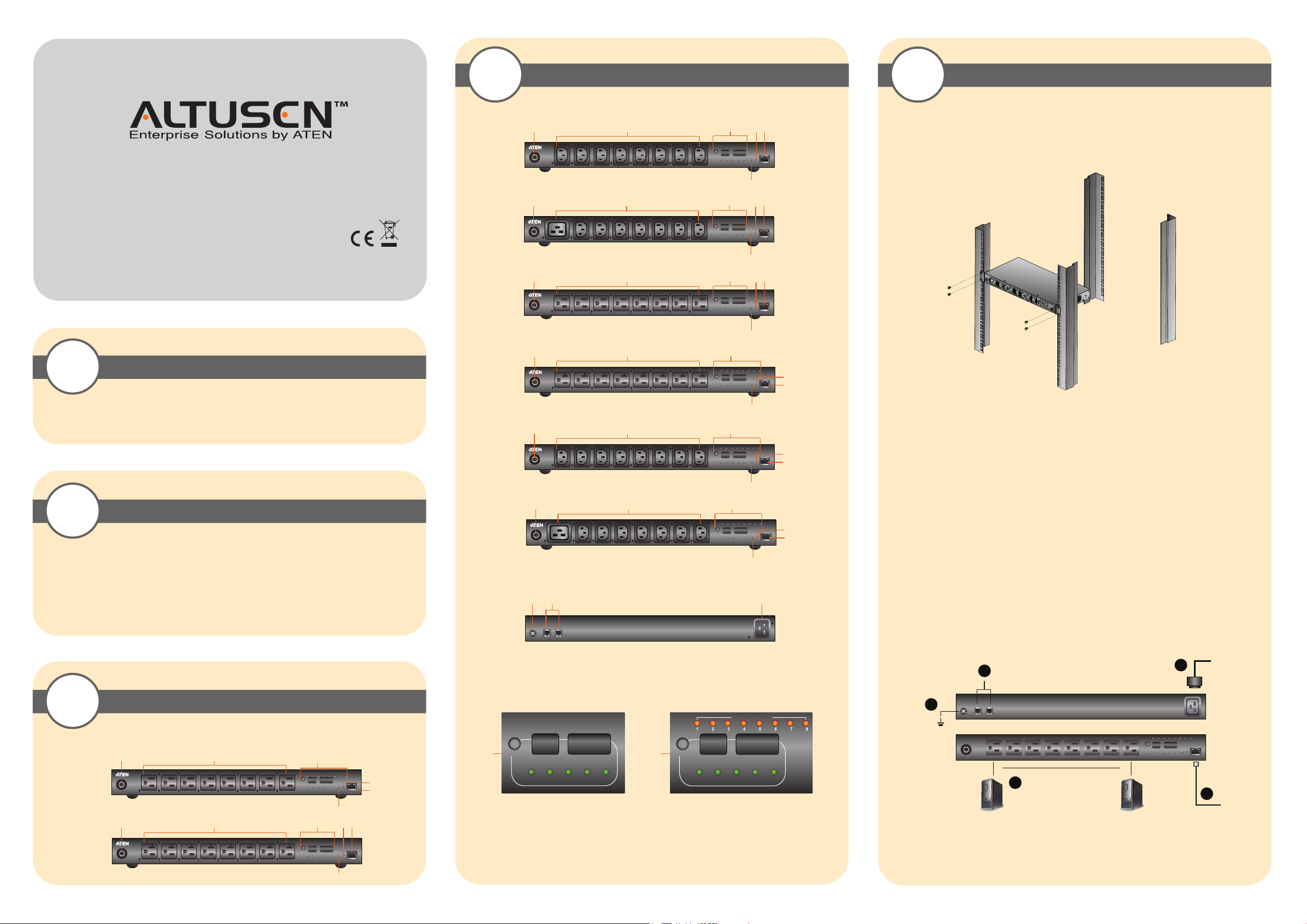
Hardware Review (Front View)
4
Hardware Installation
Online Registration
International:
• http://support.aten.com
North America:
• http://www.aten-usa.com/product_registration
eco PDU PE Series PE1108/PE1208/PE3108/
PE3208/PE6108/PE6208/PE8108/PE8208
Power Distribution Unit Quick Start Guide
© Copyright 2012 ATEN® International Co., Ltd. www.aten.com
Altusen and the Altusen logo are trademarks of ATEN International Co., Ltd.
All rights reserved. All other trademarks are the property of their respective owners.
This product is RoHS compliant PAPE-1215-900G Printing Date: 04/2012
All information, documentation, and specifications contained in this media are subject to change without prior notification by the manufacturer.
Please visit our website to find the most up to date version.
1
2
• Browsers accessing the eco PDU unit must support SSL 128 bit encryption.
• For cold booting of attached computers, the computer's BIOS must support Wake on LAN or System after AC
Back.
• For Safe Shutdown:
• The computer must be running Windows (Windows 2000 or higher) or Linux.
• The Safe Shutdown program (available by download from our website or on the software CD included), must
be installed and running on the computer.
Package Contents
1 PE1108 / PE1208 / PE3108 / PE3208 / PE6108 / PE6208 / PE8108 / PE8208
Power Distribution Unit
1 Power Cord
1 Rack Mount Kit
1 Software CD
1 User Instructions
Requirements
Technical Phone Support
International:
• 886-2-8692-6959
China:
• 86-10-5255-0110
Japan:
• 81-3-5615-5811
Korea:
• 82-2-467-6789
North America:
• 1-888-999-ATEN Ext: 4988
United Kingdom:
• 44-8-4481-58923
PE1108B / PE1108G / PE3108B / PE3108G
1
PE1208B / PE1208G / PE3208B / PE3208G
1
PE6108A / PE8108A
1
PE6208A / PE8208A
1
PE6108B / PE6108G / PE8108B / PE8108G
1
PE6208B / PE6208G / PE8208B / PE8208G
1
Rear View
7 98
2 3 4 5
6
2 3 4 5
6
2 3 4 5
6
2
3
6
2 3
6
2
3
6
Rack Mounting
The eco PDU can be mounted in a 19” (1U) rack. To rack mount the device, use the rack mounting brackets that
came with your device. The brackets can be screwed to the front or rear sides of the device, and then the unit can
slide into the front of the rack, as shown in the diagram below:
4
5
Installation
To set up your eco PDU installation, refer to the installation diagram (the numbers in the diagram correspond to the
4
5
4
5
numbered steps), and do the following:
1. Use a grounding wire to ground the eco PDU by connecting one end of the wire to its grounding terminal, and
the other end of the wire to a suitable grounded object.
Note: Do not omit this step. Proper grounding helps to prevent damage to the unit from surges or static
electricity.
2. For each device you want to connect, use its power cable to connect from the device's AC socket to any available
outlet on the eco PDU.
3. Plug the cable that connects the eco PDU to the LAN into the eco PDU's LAN port.
4. If you are using sensors in your eco PDU installation, connect them to the sensor ports on the unit’s front panel.
Note: Sensors are optional.
5. Connect the eco PDU's power cord to an AC power source.
Note: We strongly advise that you do not plug the eco PDU into a multi socket extension cord, since it may not
receive enough amperage to operate correctly.
Once you have finished these installation steps, you can turn on the eco PDU and the connected devices.
Note: We strongly recommend using cable ties and cable bars to safely and securely route the cables attached to the
front of the unit.
3-1
Front View
PE1108A / PE3108A
PE1208A / PE3208A
Hardware Review
1
1
2
2 3 4 5
Readout Section
PE1108 / PE1208 / PE3108 / PE3208 PE6108 / PE6208 / PE8108 / PE8208
OUTLET STATUS
SELECT
3
4
5
3
PDU
CURRENT
OUTLET
CURRENTIPADDRESS
SENSOR
SENSOR
2
1
SELECT
3
PDU
CURRENT
OUTLET
CURRENTIPADDRESS
SENSOR
SENSOR
2
1
1
4
2
5
3
6
1. Circuit Breaker Pushbutton
2. Power Sockets
3. Readout Section
4. Power LED
5. LAN Port and LEDs
6. Reset Switch
7. Grounding Terminal
8. Sensor Ports
9. Power Socket
6
5
Operation
Operation Methods
ALTUSEN eco PDU models provide three methods to access and manage your installation: Browser, IP Installer ,
eco Sensors, and SNMP.
Browser
The eco PDU can be accessed and controlled via any supported Internet browser from any platform.
eco Sensors
The eco PDU supports ALTUSEN eco Sensors (eco PDU Manager Software). ALTUSEN eco Sensors provides you
with an easy method for managing multiple devices, offering an intuitive and user-friendly Graphical User Interface
that allows you to configure a PDU device and monitor power status of the equipment connected to it. ALTUSEN
eco Sensors can be obtained from the Download area of our web site.
SNMP
The eco PDU supports any 3rd party V3 SNMP Manager Software. SNMP Management Information Database
(MIB) files for the eco PDU device can be found on the software CD provided with the eco PDU package.
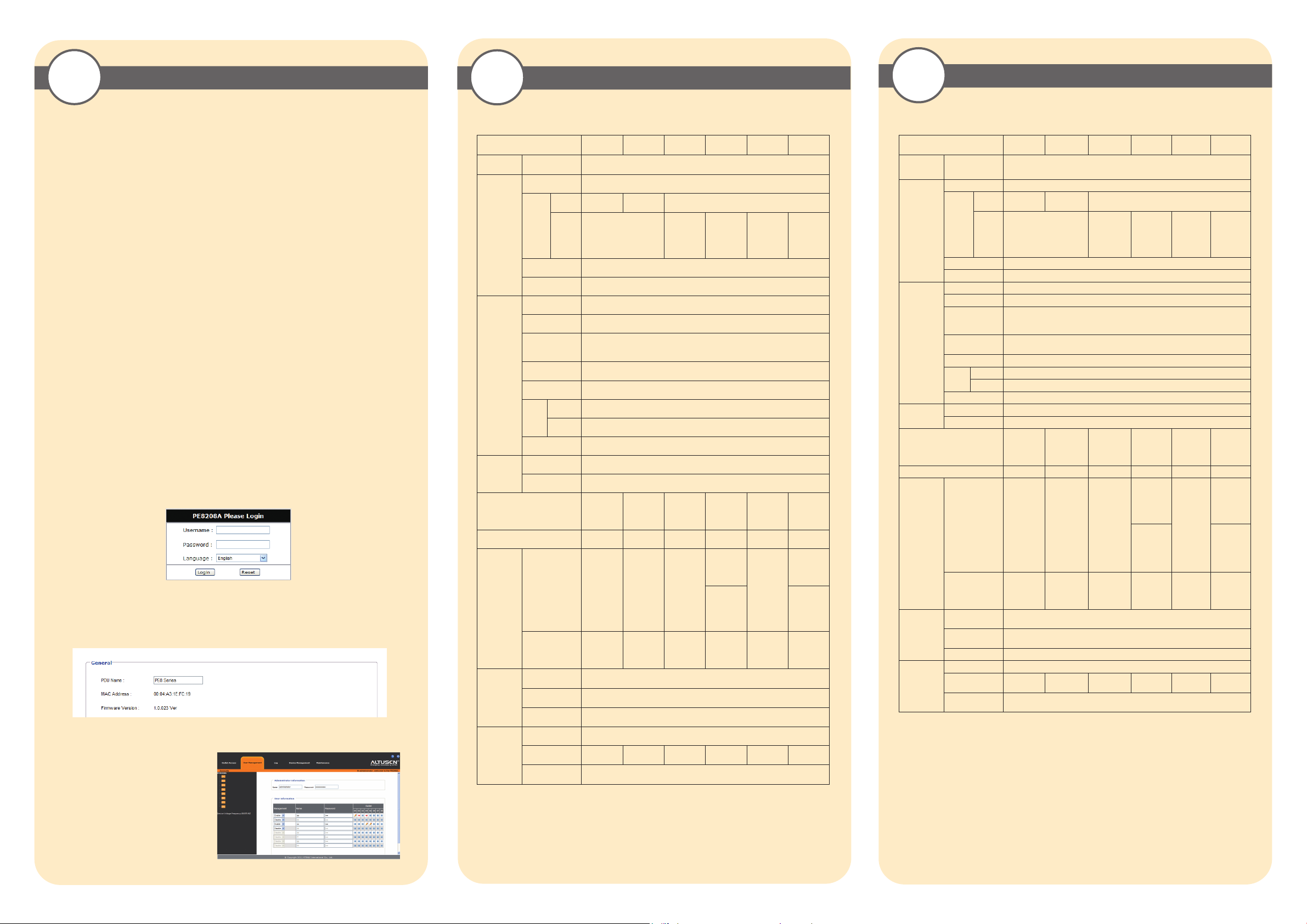
First Time Setup
Once the eco PDU installation has been cabled up, the Administrator needs to configure the network parameters,
change the default Administrator login settings, and add users. The easiest way to accomplish this is to log in over
the Net with a browser.
Browser Login
The eco PDU can be accessed via a supported Internet browser from any platform.
Note: Browsers must support SSL 128 bit encryption.
To access the eco PDU do the following:
1. Open your browser and specify the IP address of the eco PDU you want to access in the browser's URL location
bar. If you are the administrator and are logging in for first time, use the default IP address of 192.168.0.60.
Note: You must be on the same network segment as the eco PDU to use the default IP address.
2. If a Security Alert dialog box appears, accept the certificate – it can be trusted. The Login page appears:
3. Provide a valid Username and Password (set by the eco PDU administrator), then Click Login to bring up the
browser Main Page.
If you are the administrator and are logging in for the first time, use the default Username: administrator; and the
default Password: password.
Note: For security purpose we recommend purpose we recommend changing them to something unique.
Network Configuration
To set up the network, do the following:
1. Click the Device Management tab.
2. Select Device Configuration on the menu bar. A screen similar to the one below appears:
6-1
Power
Outlets
Connectors
LEDs
Switches
I/P Rating
Load Capacity 1440W 1920W 2880W 3840W 2400W 3840W
O/P Rating
Environment
Specification
Function
Direct 8
Power Inlet 1 x IEC 320 C20
Power
Outlets
Sensor 2 x RJ-11
LAN 1 x RJ-45 (Female)
Outlet Status N/A
Selection 1-digit 7-segment (Orange)
PDU Current /
Outlet Current /
IP Address
Current / IP
Address
Power 1 (Blue)
10/100M 1 (Orange / Green)
LAN
Link 1 (Green)
Sensor 2 (Green)
Reset 1 x Semi-recessed Pushbutton
Power 1 x Non-fuse Breaker
Per Port
Total
Operating
Temperature
Storage
Temperature
Humidity 0–80% RH Non-condensing
PE1108A /
PE3108A
8 x NEMA
NEMA
IEC N/A
5-15R
120V~;
50/60Hz;
120V~;
50/60Hz;
120V~;
50/60Hz;
100–
12A
100–
12A
100–
12A
PE1208A /
PE3208A
8 x NEMA
5-20R
100–
120V~;
50/60Hz;
16A
100–
120V~;
50/60Hz;
16A
100–
120V~;
50/60Hz;
16A
PE1108B /
PE3108B
8 x IEC 320
3-digit 7-segment (Orange)
240V~;
50/60Hz;
100-240V~;
50/60Hz,
100-240V~;
50/60Hz,
C13
100–
12A
12A
12A
PE1208B /
PE3208B
7 x IEC 320
C13
(Ports 2–8);
1 x C19
(Port 1)
3 (Green)
100–
240V~;
50/60Hz;
16A
Port2-8:
100-240V~;
50/60Hz,
12A
Port1:
100–
240V~;
50/60Hz;
16A
100-240V~;
50/60Hz,
16A
0–50˚C
-20–60˚C
PE1108G /
PE3108G
NA
8 x IEC 320
C13
100–
240V~;
50/60Hz;
10A
100-240V;
50/60Hz,
10A
100-240V~;
50/60Hz,
10A
PE1208G /
PE3208G
7 x IEC 320
C13
(Ports 2–8);
1 x C19
(Port 1)
100–
240V~;
50/60Hz;
16A
Port2-8:
100-240V;
50/60Hz,
10A
Port1:
100–
240V~;
50/60Hz;
16A
100-240V~;
50/60Hz,
16A
6-2
Power
Outlets
Connectors
LEDs
Switches
I/P Rating
Load Capacity 1440W 1920W 2880W 3840W 2400W 3840W
O/P Rating
Environment
Physical
Properties
Specification
Function
Direct 8
Power Inlet 1 x IEC 320 C20
Power
Outlets
Sensor 2 x RJ-11
LAN 1 x RJ-45 (Female)
Outlet Status 8 (Orange)
Selection 1-digit 7-segment (Orange)
PDU Current /
Outlet Current /
IP Address
Current / IP
Address
Power 1 (Blue)
10/100M 1 (Orange / Green)
LAN
Link 1 (Green)
Sensor 2 (Green)
Reset 1 x Semi-recessed Pushbutton
Power 1 x Non-fuse Breaker
Per Port
Total
Operating
Temperature
Storage
Temperature
Humidity 0–80% RH Non-condensing
Housing Metal
Weight
Dimensions
(L x W x H)
PE6108A /
PE8108A
8 x NEMA
NEMA
IEC N/A
5-15R
100–
120V~;
50/60Hz;
100–
120V~;
50/60Hz;
100–
120V~;
50/60Hz;
2.77 kg /
2.80 kg
12A
12A
12A
PE6208A /
PE8208A
8 x NEMA
5-20R
100–120V~;
50/60Hz;
16A
100–120V~;
50/60Hz;
16A
100–120V~;
50/60Hz;
16A
2.77 kg /
2.82 kg
PE6108B /
PE8108B
8 x IEC 320
3-digit 7-segment (Orange)
100–240V~;
50/60Hz;
100-240V~;
50/60Hz,
100-240V~;
50/60Hz,
2.82 kg /
2.87 kg
43.24 x 21.93 x 4.40 cm
C13
3 (Green)
12A
12A
12A
0–50˚C
-20–60˚C
PE6208B/
PE8208B
7 x IEC 320
C13
(Ports 2–8);
1 x C19
(Port 1)
100–
240V~;
50/60Hz;
16A
Port2-8:
100-
240V~;
50/60Hz,
12A
Port1:
100-
240V~;
50/60Hz,
16A
100-
240V~;
50/60Hz,
16A
2.79 kg /
2.87 kg
PE6108G /
PE8108G
N/A
8 x IEC
320 C13
240V~;
50/60Hz;
240V~;
50/60Hz,
240V~;
50/60Hz,
2.82 kg /
2.87 kg
100–
10A
100-
10A
100-
10A
PE6208G/
PE8208G
7 x IEC
320 C13
(Ports 2–8);
1 x C19
(Port 1)
100–
240V~;
50/60Hz;
16A
Port2-8:
100-
240V~;
50/60Hz,
10A
Port1:
100-
240V~;
50/60Hz,
16A
100-
240V~;
50/60Hz,
16A
2.79 kg /
2.87 kg
Changing the Administrator Login
To change the default Administrator username
and password, do the following:
1.Click the User Management tab.
2. In the Administrator Information section,
reset the name and password fields to
something unique, then click Save (at the
bottom of the page.)
Physical
Properties
Housing Metal
Weight
Dimensions
(L x W x H)
2.63Kg /
2.68Kg
2.64Kg /
2.69Kg
2.70 kg /
2.73 kg
43.24 x 21.93 x 4.40 cm
2.71 kg /
2.74 kg
2.70 kg /
2.72 kg
2.71 kg /
2.74 kg
 Loading...