


KL1508Ai
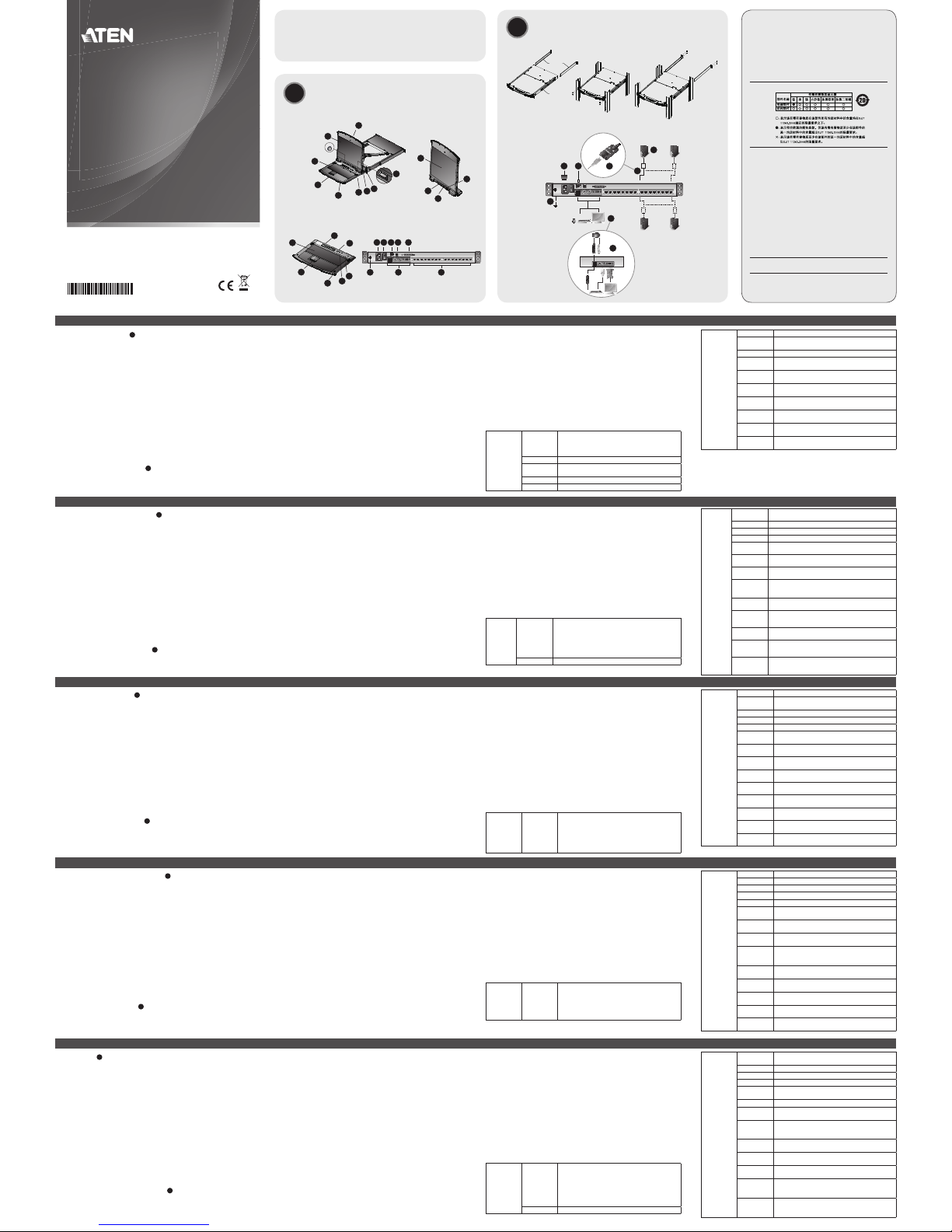
Hardware Review A
Front View
1. Upper Handle
2. LCD Module
3. Keyboard Module
4. Lower Handle
5. Power LED
6. Keyboard Release Catch
7. LCD Release Catch
8. Rack Mounting Tabs
9. LED Illumination Light
Keyboard Module
1. Keyboard
2. Touchpad
3. External Mouse Port
4. Station ID LED
5. Station Selection Area
6. Lock LEDs & Reset Switch
7. Port Selection Buttons and LEDs
Hardware Installation B
Standard rack mounting
1. While one person positions the switch in the rack and holds it in place, the second
person loosely screws the front brackets to the rack.
Description de l’appareil A
Vue avant
1. Poignée supérieure
2. Module LCD
3. Module clavier
4. Poignée inférieure
5. Voyant d’alimentation
6. Loquet de libération du clavier
7. Loquet de libération de l’écran LCD
8. Supports de fi xation pour montage sur bâti
9. Eclairage LED
Module clavier
1. Clavier
2. Pavé tactile
3. Port souris externe
4. Voyant d'ID de station
5. Zone de sélection des stations
6. Voyants de verrouillage et bouton de réinitialisation
7. Boutons de sélection de port et voyants
Installation du matériel B
Montage sur bâti
1. Pendant qu'une première personne positionne le commutateur dans le bâti et le
maintient en place, une deuxième visse les supports avant sur le bâti.
Hardwareübersicht A
Vorderseite
1. Griff oben
2. LCD-Modul
3. Tastaturmodul
4. Griff unten
5. LED-Betriebsanzeige
6. Entriegelungstaste für Tastatur
7. Entriegelungstaste für LCD
8. Arretierungen für Rack-Montage
9. LED-Beleuchtung
Tastaturmodul
1. Tastatur
2. Touchpad
3. Externer Mausanschluss
4. Stations-ID-LED
5. Stationswahlbereich
6. LEDs für Feststellfunktionen und Reset-Taste
7. Portauswahltasten und LED-Anzeigen
Hardware installieren B
Rack-Montage
1. Während die eine Person den Switch in den Rack schiebt und festhält, setzt die zweite
Person die Schrauben lose auf die Montageschienen.
2. Während die erste Person den Switch nach wie vor festhält, schiebt die zweite die
L-Schienen von hinten auf die seitlichen Montagerahmen des Switches, bis der Flansch
Presentación del hardware A
Vista frontal
1. Mango superior
2. Módulo LCD
3. Módulo de teclado
4. Mango inferior
5. Indicador LED de alimentación
6. Botón de desbloqueo del teclado
7. Botón de desbloqueo LCD
8. Muescas para montaje en rack
9. Iluminacion LED
Módulo de teclado
1. Teclado
2. Panel táctil
3. Puerto para mouse externo
4. Indicador LED de ID de estación
5. Área de selección de estación
6. LEDs de bloqueo y pulsador de reseteo
7. Botones de selección e indicadores LED de puertos
Instalar el hardware B
Montaje en rack
1. Mientras una persona coloca el conmutador en el rack y lo aguanta en su sitio, una
segunda atornilla (sin apretar) la parte frontal de los rieles en el rack.
2. Mientras la primera persona sigue aguantando el conmutador, la segunda desliza los
Hardware A
Vista anteriore
1. Maniglia superiore
2. Modulo LCD
3. Modulo tastiera
4. Maniglia inferiore
5. LED d’alimentazione
6. Fermo di sganciamento della tastiera
7. Fermo di sganciamento del monitor LCD
8. Linguette per il montaggio in rack
9. Illuminazione LED
Modulo tastiera
1. Tastiera
2. Touchpad
3. Porta esterna del mouse
4. LED dell’ID di stazione
5. Area di selezione della stazione
6. LED di bloccaggio e interruttore di ripristino
7. Pulsanti e LED di selezione della porta
Installazione dell’hardware B
Montaggio in rack
1. Mentre una persona posiziona lo switch nel rack e lo tiene in posizione, la seconda
persona avvita leggermente le staffe anteriori al rack.
2. Mentre la prima persona continua a tenere in posizione lo switch, la seconda fa
2. While the fi rst person still holds the switch in place, the second person slides the L
brackets into the switch's side mounting brackets, from the rear until the bracket
fl anges contact the rack, then screws the L brackets to the rack.
3. After the L brackets have been secured, tighten the front bracket screws.
Note: Allow at least 5.1 cm on each side for proper ventilation, and at least 12.7 cm at
the back for the power cord and cable clearance
Single Station Installation
1. Ground the KL1508Ai / KL1516Ai by connecting one end of the grounding wire to the
grounding terminal, and the other end of the wire to a suitable grounded object.
Note: Do not omit this step. Proper grounding helps to prevent damage to the unit
from surges or static electricity.
2. If you choose to install an external console, plug your keyboard, monitor, and mouse
into the Console Ports located on the switch’s rear panel. The ports are color coded and
marked with an icon to identify themselves.
Note: This step is optional.
3. For each of the computers you are installing, use Cat 5e cable to connect any available
KVM port to a KVM adapter cable that is appropriate for the computer you are
installing.
Note: The maximum supported distance to the adapter cable is 50 m.
4. Connect the KVM Adapter cable to the computer. Plug the adapter cable connectors
into their respective ports on the computers you are installing.
5. Plug the LAN or WAN cable into the KL1508Ai / KL1516Ai’s LAN port.
6. Connect the power cord to the switch and to an AC power source
After the KL1508Ai / KL1516Ai is cabled up, you can turn on the power. After the switch
is powered up, you can turn on the servers.
2. Pendant que la première personne maintient toujours en place le commutateur, la
deuxième fait glisser les supports en L dans les supports de montage latéraux du
commutateur (à l'arrière) jusqu'à ce que les brides des supports entrent en contact avec
le bâti, puis visse les supports en L sur le bâti.
3. Une fois les supports en L bien en place, serrez les vis des supports avant.
Remarque : Laissez au moins 5,1 cm de chaque côté pour une ventilation appropriée
et au moins 12,7 cm à l’arrière pour accueillir le câble et le cordon
d’alimentation.
Installation d'une seule station
1. Raccordez le KL1508Ai / KL1516Ai à la terre en reliant une extrémité du câble de mise
à la terre à la prise de terre et l'autre extrémité à un objet correctement mis à la terre.
Remarque : Ne sautez pas cette étape. Une mise à la terre correcte protège l'appareil
de l'électricité statique et des surtensions.
2. Si vous souhaitez installer une console externe, branchez le clavier, le moniteur et
la souris sur les ports de console situés à l'arrière du commutateur. Les ports sont
identifi ables grâce à un code de couleur et une icône spécifi que.
Remarque : cette étape est facultative.
3. Pour chacun des ordinateurs à installer, utilisez un câble de catégorie 5e pour relier un
port KVM disponible à un câble adaptateur KVM convenant à l'ordinateur à installer.
Remarque : La distance maximale entre l’unité et le câble adaptateur est de 50 m.
4. Connectez le câble adaptateur KVM à l'ordinateur. Branchez les connecteurs du câble
adaptateur KVM sur les ports appropriés de l'ordinateur que vous installez.
5. Branchez le câble LAN ou WAN sur le port LAN du KL1508Ai / KL1516Ai.
6. Branchez le cordon d’alimentation au commutateur et à une source d’alimentation CA.
Une fois le KL1508Ai / KL1516Ai câblé, vous pouvez le mettre sous tension. Une fois qu’il
est allumé, vous pouvez mettre les serveurs sous tension.
den Rack berührt. Schrauben Sie die L-Schienen anschließend am Rack fest.
3. Nachdem Sie die L-Schienen befestigt haben, ziehen Sie auch die Schrauben an der
Vorderseite fest.
Hinweis: Achten Sie darauf, dass mindestens 5 cm Abstand auf jeder Seite frei bleiben,
um eine ausreichende Lüftung zu gewährleisten und 12,7 cm auf der
Rückseite für die Durchführung des Netzkabels und der anderen Kabel.
Einzelinstallation
1. Erden Sie den KL1508Ai / KL1516Ai mithilfe des Erdleiters. Verbinden Sie dazu das eine
Ende des Leiters mit der Erdungsschelle und das andere Ende mit einem geerdeten
Gegenstand.
Hinweis: Überspringen Sie diesen Schritt keinesfalls. Eine ordnungsgemäße Erdung
schützt das Gerät vor Spannungsspitzen und statischer Elektrizität.
2. Wenn Sie eine externe Konsole anschließen möchten, verbinden Sie Tastatur, Maus und
Monitor mit den Konsolanschlüssen auf der Geräterückseite. Die Stecker und Buchsen
sind farblich und mit einem Symbol gekennzeichnet.
Hinweis: Dieser Schritt ist optional.
3. Verbinden Sie für jeden der anzuschließenden Computer einen der noch freien KVMPorts mit einem KVM-Adapterkabel, das für den anzuschließenden Computer geeignet
ist. Verwenden Sie dazu ein Kat. 5e-Kabel.
Hinweis: Die maximale Entfernung zum Adapterkabel darf 50 m nicht überschreiten.
4. Verbinden Sie das KVM-Adapterkabel mit dem Computer. Verbinden Sie die Stecker des
Adapterkabels mit den betreffenden Ports der anzuschließenden Computer.
5. Verbinden Sie das LAN- oder WAN-Kabel mit dem LAN-Anschluss des KL1508Ai /
KL1516Ai.
6. Schließen Sie das Netzkabel an den Switch und an eine geeignete Stromquelle an.
rieles en L sobre el conmutador desde la parte trasera hasta que la pestaña del soporte
haga contacto con el rack y luego atornilla los rieles en L al rack.
3. Cuando tenga los rieles en L atornillados, apriete los tornillos frontales de los rieles.
Nota: Deje al menos 5,1 cm de espacio en cada lado a fi nes de ventilación y al menos
12,7 cm de espacio posterior para el cable de alimentación y los demás cables.
Instalación de estación individual
1. Conecte el KL1508Ai / KL1516Ai a tierra. Para ello, conecte un extremo del cable
de tierra incluido a la toma de tierra y el otro extremo a un objeto correctamente
conectado a tierra.
Nota: no omita este paso. Una conexión correcta a tierra protege a la unidad de la
electricidad estática y de las subidas de tensión.
2. Si desea instalar una consola externa, conecte su teclado, su monitor y su mouse a los
puertos de consola ubicados en el panel posterior del conmutador. Los puertos llevan el
código de color estándar, además de un icono para su identifi cación.
Nota: este paso es opcional.
3. Para cada una de las computadoras que desee instalar, utilice un cable de Cat. 5e
para conectar un puerto KVM disponible a un cable adaptador KVM adecuado para la
computadora que vaya a instalar.
Nota: La máxima distancia admitida al cable adaptador es de 50 m.
4. Conecte el cable adaptador KVM a la computadora. Enchufe los conectores del cable
adaptador KVM en los puertos correspondientes de las computadoras que quiera
instalar.
5. Conecte el cable LAN o WAN al puerto LAN del KL1508Ai / KL1516Ai.
6. Conecte el cable de alimentación al conmutador y a una toma eléctrica.
Una vez conectados los cables al KL1508Ai / KL1516Ai, puede encenderlo. A
continuación, encienda los servidores.
scivolare le staffe a L nei supporti laterali di montaggio dello switch, partendo dal retro,
fi no a quando non sono a stretto contatto con il rack e poi avvita le staffe a L al rack.
3. Una volta fi ssati i supporti a L, stringere le viti dei supporti anteriori.
Nota: Lasciare almeno 5,1 cm da ogni lato per garantire l’appropriata ventilazione ed
almeno 12,7 cm sul retro per il cavo d’alimentazione e la rimozione dei cavi.
Installazione singola
1. Utilizzare il fi lo in dotazione per la messa a terra del KL1508Ai/KL1516Ai, collegando
un’estremità del fi lo all’apparecchio da mettere a terra e l’altra estremità a un
dispositivo dotato di adeguata messa a terra.
Nota: Non saltare questo passo. Un’appropriata messa a terra contribuisce a evitare i
danni al dispositivo derivanti da picchi di tensione o elettricità statica.
2. Se si decide di installare una console esterna, collegare la tastiera, il mouse ed il monitor
alle porte di collegamento alla console poste sul pannello posteriore dello switch.
Le porte seguono un codice a colori e sono contrassegnate da un’icona, per essere
identifi cate facilmente.
Nota: Questa operazione è opzionale.
3. Per ogni computer che si sta installando utilizzare il cavo Cat. 5e per collegare una
porta KVM disponibile ad un cavo adattatore KVM adeguato al computer.
Nota: La distanza massima supportata per il cavo adattatore è di 50 m.
4. Collegare il cavo adattatore KVM al computer. Inserire i connettori del cavo adattatore
nelle relative porte del computer che si sta installando.
5. Inserire la spina del cavo LAN o WAN nella porta LAN del KL1508Ai / KL1516Ai.
6. Collegare il cavo d’alimentazione allo switch e a una fonte di corrente CA adatta.
Una volta collegato il KL1508Ai / KL1516Ai, accenderlo. Una volta acceso il dispositivo è
possibile accendere i server.
Operation
KL1508Ai / KL1516Ai installations provide three methods to obtain instant access to any
computer on your installation: Manual, OSD (on-screen display)/GUI, and Hotkey.
Manual
For manual port selection, simply press the Port Switch that corresponds to the device you
wish to access.
OSD
The On Screen Display (OSD) is a menu driven method to handle computer control and
switching operations. All procedures start from the OSD Main Screen. To display the Main
Screen, tap the OSD hotkey twice. The default hotkey is [Scroll Lock]. You can change the
hotkey to the Ctrl key or the Alt key if you like.
Hotkey Summary Table
[Num Lock] +
[-] or [Ctrl] +
[F12]
[A] [Enter]
Invokes Auto Scan mode. When Auto Scan mode is
in effect, [P] or left-click pauses auto-scanning. When
auto-scanning is paused, pressing any key or another
left-click resumes auto-scanning.
[B] Toggles the Beeper On or Off.
[Esc] or
[Spacebar]
Exits hotkey mode.
[F1] Sets Operating System to Windows.
[F2] Sets Operating System to Mac.
Utilisation
Les installations incluant un commutateur KL1508Ai / KL1516Ai offrent trois méthodes
permettant d’accéder instantanément à n’importe quel ordinateur de l’installation : Accès
manuel, par affi chage à l’écran (OSD) / interface utilisateur graphique et par raccourci
clavier.
Accès manuel
Pour sélectionner un port manuellement, appuyez simplement sur le commutateur de
sélection de port correspondant au périphérique auquel vous souhaitez accéder.
OSD
L'affi chage OSD offre un menu permettant de contrôler l'ordinateur et les opérations
de commutation. Toutes les procédures s'effectuent à partir de l'écran principal de
l'OSD. Pour affi cher le menu principal, appuyez deux fois sur la touche de raccourci
correspondant à l'OSD. Il s’agit de la touche [Arrêt défi l]. Vous pouvez modifi er la touche
de raccourci et utiliser la touche Ctrl ou Alt à la place si vous le souhaitez.
Résumé des raccourcis clavier
[Verr. num] +
[-] ou [Ctrl] +
[F12]
[A] [Entrée]
Permet d’activer la Commutation automatique. Lorsque la
Commutation automatique est activée, appuyez sur [P] ou
cliquez avec le bouton gauche de la souris pour suspendre
la recherche. Lorsque la commutation automatique est
suspendue, appuyez sur n’importe quelle touche ou cliquez
avec le bouton gauche de la souris pour reprendre la
recherche.
[B] Permet d’activer ou désactiver le bip sonore.
Nachdem alle Kabelanschlüsse am KL1508Ai / KL1516Ai hergestellt wurden, können Sie
das Gerät einschalten. Nachdem der Switch eingeschaltet wurde, können Sie auch die
angeschlossenen Server einschalten.
Bedienung
Der KL1508Ai / KL1516Ai bietet drei verschiedene Möglichkeiten, die Konsole umgehend
auf einen anderen Computer zu legen: Manuell, über das OSD-Menü/grafi sche
Benutzeroberfl äche und über Hotkey-Tastenkombinationen.
Manuell
Um einen Port manuell auszuwählen, drücken Sie den Port-Auswahlschalter, der den Port
des Gerätes darstellt, auf das Sie zugreifen möchten.
OSD
Das OSD-Menü ist ein Bildschirmmenü, über das Sie die Computer und den Switch
bedienen können. Alle Funktionen werden über das OSD-Menü aufgerufen. Um das
Hauptmenü zu öffnen, drücken Sie zweimal die OSD-Hotkey. Standardmäßig ist die OSDHotkey auf die Taste [Rollen] gelegt. Sie können sie bei Bedarf aber auch auf die Taste Strg
oder Alt legen.
Hotkey-Übersichtstabelle
[Num] + [-]
oder [Strg] +
[F12]
[A] [Enter]
Startet die automatische Portumschaltung. Während
der automatischen Portumschaltung drücken Sie die
Taste [P] oder klicken mit der linken Maustaste, um
diese vorübergehend anzuhalten. Ist die automatische
Portumschaltung angehalten, können Sie sie durch
Drücken einer beliebigen Taste bzw. Klicken mit der
linken Maustaste fortsetzen.
Funcionamiento
El KL1508Ai / KL1516Ai ofrece tres posibilidades de obtener acceso instantáneo a
cualquier computadora conectada. Manual, por menú OSD (menú en pantalla) / interfaz
gráfi ca y teclas de acceso directo.
Manual
Para seleccionar manualmente un puerto, pulse el conmutador de puerto que corresponde
al puerto donde tiene conectado el dispositivo en cuestión.
Menú OSD
El menú OSD en pantalla es una forma de controlar las funciones y la conmutación de
computadoras a través de un menú. Todos los procedimientos tienen su origen en la
pantalla principal del OSD. Para mostrar el menú principal, pulse dos veces la tecla de
acceso al OSD. La tecla de acceso directo predeterminada es [Bloq Despl]. Si lo desea,
puede reasignar la tecla de acceso directo a la tecla Ctrl o a la tecla Alt.
Sumario de las teclas de acceso directo
[Bloq Num] +
[-] o [Ctrl] +
[F12]
[A] [Intro]
Activa el modo de conmutación automática. Pulse
la tecla [P] o haga clic con el botón izquierdo del
ratón para detener la conmutación automática
temporalmente. Pulse cualquier tecla o haga clic con el
botón izquierdo del ratón para reanudar la conmutación
automática.
Funzionamento
Le installazioni del KL1508Ai/ KL1516Ai offrono tre metodi per ottenere un accesso
istantaneo a qualsiasi computer dell’installazione: Manuale, OSD (on-screen display)/GUI e
Tasto di scelta rapida.
Manuale
Per selezionare una porta manualmente, premere l’interruttore della porta corrispondente
al dispositivo a cui si desidera accedere.
OSD
L’OSD (On Screen Display) è un metodo di utilizzo dei comandi del computer e delle
operazioni di commutazione tramite menu. Tutte le procedure partono dalla schermata
principale OSD. Per visualizzare la schermata principale, premere due volte il tasto di scelta
rapida dell’OSD. Il tasto di scelta rapida predefi nito è [Bloc Scorr]. A questo punto, se si
desidera, è possibile cambiare il tasto di scelta rapida con il tasto Ctrl o Alt.
Tabella di riepilogo dei tasti di scelta rapida
[Bloc Num] +
[ - ] o [Ctrl] +
[F12]
[A] [Invio]
Richiama la modalità Commutazione automatica.
Quando la modalità commutazione automatica è
attiva, premendo [P] o facendo clic con il tasto sinistro
del mouse si mette in pausa tale modalità. Quando
la modalità commutazione automatica è in pausa,
premendo un tasto qualsiasi o facendo clic nuovamente
con il tasto sinistro del mouse si riattiva tale modalità.
[B] Attiva e disattiva il segnale acustico.
[Num Lock] +
[-] or [Ctrl] +
[F12]
[F3] Sets Operating System to Sun.
[F5]
Performs a keyboard / mouse reset on the target
computer.
[H] Toggles the Hotkey invocation keys.
[Port ID] [Enter]
Switches access to the computer that corresponds to
that Port ID.
[R] [Enter]
Administrator only hotkey. It returns the switch’s
settings to their default values.
[T]
Toggles the OSD Hotkey between [Ctrl] [Ctrl] and [Scroll
Lock] [Scroll Lock].
[←]
Invokes Skip Mode and skips from the current port to
the fi rst accessible port previous to it.
[→]
Invokes Skip Mode and skips from the current port to
the next accessible port.
[↑]
Invokes Skip Mode and skips from the current port to
the last accessible port of the previous Station.
[↓]
Invokes Skip Mode and skips from the current port to
the fi rst accessible port of the next Station.
[Verr. num] +
[-] ou [Ctrl] +
[F12]
[Echap] ou
[Barre d’espace]
Permet de quitter le mode raccourcis clavier.
[F1] Permet de choisir le système d’exploitation Windows.
[F2] Permet de choisir le système d’exploitation Mac.
[F3] Permet de choisir le système d’exploitation Sun.
[F5]
Permet d’effectuer une réinitialisation clavier / souris sur
l’ordinateur cible.
[H]
Permet de changer les touches utilisées pour l’activation du
mode raccourcis clavier.
[ID de port]
[Entrée]
Permet de basculer l'accès vers l'ordinateur correspondant à
cet ID de port.
[R] [Entrée]
Raccourci clavier uniquement destiné à l’administrateur.
Il permet de rétablir les paramètres par défaut du
commutateur.
[T]
Permet de faire basculer le raccourci clavier de l’OSD entre
[Ctrl] [Ctrl] et [Arrêt défi l] [Arrêt défi l].
[←]
Permet d’activer le mode de changement de ports et
de passer du port en cours au premier port accessible le
précédant.
[→]
Permet d’activer le mode de changement de ports et de
passer du port actuel au port accessible suivant.
[↑]
Permet d’activer le mode de changement de ports et de
passer du port actuel au dernier port accessible de la station
précédente.
[↓]
Permet d’activer le mode de changement de ports et de
passer du port en cours au premier port accessible de la
station suivante.
[Num] + [-]
oder [Strg] +
[F12]
[B] Schaltet die Tonsignale ein bzw. aus.
[Esc] oder
[Leertaste]
Beendet den Hotkey-Modus.
[F1] Legt Windows als Betriebssystem fest.
[F2] Legt Mac als Betriebssystem fest.
[F3] Legt Sun als Betriebssystem fest.
[F5]
Setzt alle Tastatur- und Mauszuordnungen am
Zielcomputer zurück.
[H]
Schaltet zwischen den verschiedenen HotkeyAktivierungstasten um.
[Port ID] [Enter]
Schaltet auf den Computer um, der an diesen Port
angeschlossen ist.
[R] [Enter]
Hotkey nur für Administratoren. Stellt die
Standardeinstellungen des Switches wieder her.
[T]
Schaltet die OSD-Hotkey von [Strg] [Strg] auf [Rollen]
[Rollen] um, und umgekehrt.
[←]
Schaltet vom aktuellen Port zum erstmöglichen vorigen
Port, der verfügbar ist, um.
[→]
Schaltet vom aktuellen Port zum nächstmöglichen Port,
der verfügbar ist, um.
[↑]
Schaltet vom aktuellen Port zum letzten verfügbaren
Port der vorigen Station um.
[↓]
Schaltet vom aktuellen Port zum ersten verfügbaren
Port der folgenden Station um.
[Bloq Num] +
[-] o [Ctrl] +
[F12]
[B] Activa o desactiva las señales acústicas.
[Esc] o [Espacio] Sale del modo de teclas de acceso directo.
[F1] Establece el sistema operativo Windows.
[F2] Establece el sistema operativo Mac.
[F3] Establece el sistema operativo Sun.
[F5]
Resetea los ajustes para teclado y ratón en el ordenador
remoto.
[H]
Alterna las teclas de activación para el modo de teclas
de acceso directo.
[ID del puerto]
[Intro]
Da acceso al ordenador al que le corresponde el ID de
puerto seleccionado.
[R] [Intro]
Teclas de acceso directo para el Administrador
exclusivamente. Restablece el conmutador a los valores
predeterminados.
[T]
Alterna la tecla de acceso directo del OSD entre [Ctrl]
[Ctrl] y [Bloq Despl] [Bloq Despl].
[←]
Pasa al primer puerto anterior accesible a partir del
Puerto actual.
[→]
Pasa del puerto actual al primer puerto posterior
accesible.
[↑]
Pasa del puerto actual al último puerto accesible de la
estación anterior.
[↓]
Pasa del puerto actual al primer puerto accesible de la
estación siguiente.
[Bloc Num] +
[ - ] o [Ctrl] +
[F12]
[Esc] o [barra
spaziatrice]
Esce dalla Modalità tasto di scelta rapida.
[F1] Imposta il sistema operativo su Windows.
[F2] Imposta il sistema operativo su Mac.
[F3] Imposta il sistema operativo su Sun.
[F5]
Esegue un ripristino di tastiera / mouse sul computer in
oggetto.
[H] Attiva e disattiva i tasti di scelta rapida.
[ID della porta]
[Invio]
Cambia l’accesso sul computer corrispondente a
quell’ID della porta.
[R] [Invio]
Tasto di scelta rapida destinato solo all'amministratore.
Ripristina i valori predefi niti delle impostazioni dello
switch.
[T]
Cambia i tasti di scelta rapida dell’OSD da [Ctrl] [Ctrl] a
[Bloc Scorr] [Bloc Scorr] e viceversa.
[←]
Richiama la modalità Passa a e passa dalla porta
corrente alla prima porta accessibile precedente.
[→]
Richiama la modalità Passa a e passa dalla porta
corrente alla prima porta accessibile successiva.
[↑]
Richiama la modalità Passa a e passa dalla porta
corrente all’ultima porta accessibile della stazione
precedente.
[↓]
Richiama la modalità Passa a e passa dalla porta
corrente alla prima porta accessibile della stazione
successiva.
B
Package Contents
1 KL1508Ai or KL1516Ai Dual Rail LCD KVM Switch
1 Power Cord
1 Standard Rack Mount Kit
1 Firmware Upgrade Cable
1 User Instructions
Hardware Installation
© Copyright 2015 ATEN® International Co., Ltd.
ATEN and the ATEN logo are trademarks of ATEN International Co., Ltd. All rights reserved. All
other trademarks are the property of their respective owners.
This product is RoHS compliant.
Part No. PAPE-1223-D20G Printing Date: 02/2015
Dual Rail LCD KVM Switch
Quick Start Guide
KL1508Ai/KL1516Ai
KL1508Ai/KL1516Ai Dual Rail LCD KVM Switch Quick Start Guide
www.aten.com
Guide de mise en route rapide du commutateur LCD KVM à double rail KL1508Ai / KL1516Ai
www.aten.com
KL1508A/KL1516A Dualer, ausziehbarer Kat. 5 High-Density KVM-Switch mit LCD und 8/16 Ports Kurzanleitung
www.aten.com
Conmutador KVM con dos módulos retráctiles y pantalla LCD KL1508Ai / KL1516Ai Guía rápida
www.aten.com
KL1508Ai / KL1516Ai Dual Rail LCD KVM Switch – Guida rapida
www.aten.com
ATEN Altusen
™
LCD Module
1. LCD Display
2. LCD Controls
3. LCD On/Off Button
4. Firmware Upgrade Section
Rear View
1. Grounding Terminal
2. Power Socket
3. Power Switch
4. LAN Port
5. PON Port
6. Daisy Chain Port
7. Local Console Port Selection
8. KVM Port Selection
Module LCD
1. Écran LCD
2. Commandes LCD
3. Bouton marche/arrêt de l'écran LCD
4. Section de mise à niveau du
microprogramme
Vue arrière
1. Prise de terre
2. Prise d'alimentation
3. Interrupteur
4. Port LAN
5. Port PON
6. Port de connexion en chaîne
7. Sélection des ports de la console locale
8. Sélection des ports KVM
L Brackets
Side Mounting
Bracket (Typ.)
Standard rack mounting
Single Station Installation
6 5
4
3
1
2
3
2
1
1
1
2
2
3
2
3
5
3
4
4
4
5
6
6
7
8
9
7
2 3 4 5 6
1 7 8
Press the Exit/Light pushbutton
for two seconds to turn the
LED light ON or Off. (Default: On)
EXIT I LIGHT
LCD-Modul
1. LCD-Display
2. LCD-Bedienelemente
3. Ein-/Ausschalter für LCD-Schirm
4. Abschnitt zur Firmwareaktualisierung
Rückseitige Ansicht
1. Erdungsanschluss
2. Netzeingangsbuchse
3. Netzschalter
4. LAN-Port
5. PON-Anschluss
6. Port für Reihenschaltung
7. Lokale Konsolportauswahl
8. KVM-Portauswahl
Módulo LCD
1. Pantalla LCD
2. Controles LCD
3. Botón LCD encendido/apagado
4. Sección para actualizaciones del fi rmware
Vista posteriort
1. Toma de tierra
2. Entrada de alimentación
3. Interruptor de alimentación
4. Puerto LAN
5. Puerto PON
6. Puerto para conexión en margarita
7. Selección de puertos de consola local
8. Selección de puertos KVM
Modulo LCD
1. Display a cristalli liquidi
2. Comandi LCD
3. Pulsante di accensione/spegnimento
dello schermo
4. Sezione per l’aggiornamento del
fi rmware
Vista posteriore
1. Terminale di messa a terra
2. Presa per l’alimentazione
3. Interruttore di alimentazione
4. Porta LAN
5. Porta PON
6. Porta di connessione in cascata
7. Sezione delle porte della console locale
8. Selezione della porta KVM
Important Notice
Considering environmental protection, ATEN does not provide a fully
printed user manual for this product. If the information contained in the
Quick Start Guide is not enough for you to confi gure and operate your
product, please visit our website www.aten.com, and download
the full user manual.
Online Registration
http://eservice.aten.com
Technical Phone Support
International:
886-2-86926959
All information, documentation, firmware, software utilities, and
specifi cations contained in this package are subject to change without
prior notification by the manufacturer. Please visit our website http://
www.aten.com/download/?cid=dds for the most up-to-date versions.
이 기기는 업무용(A급) 전자파 적합기기로서 판매자 또는 사용자는 이점
을 주의하시기 바라며, 가정외의 지역에서 사용하는 것을 목적으로합니다.
The following contains information that relates to China:
North America:
1-888-999-ATEN Ext: 4988
United Kingdom:
44-8-4481-58923
EMC Information
FEDERAL COMMUNICATIONS COMMISSION INTERFERENCE STATEMENT:
This equipment has been tested and found to comply with the limits for a Class A
digital device, pursuant to Part 15 of the FCC Rules. These limits are designed to provide
reasonable protection against harmful interference when the equipment is operated
in a commercial environment. This equipment generates, uses, and can radiate radio
frequency energy and, if not installed and used in accordance with the instruction
manual, may cause harmful interference to radio communications. Operation of this
equipment in a residential area is likely to cause harmful interference in which case the
user will be required to correct the interference at his own expense.
FCC Caution: Any changes or modifi cations not expressly approved by the party
responsible for compliance could void the user's authority to operate this equipment.
CE Warning: This is a class A product. In a domestic environment this product may cause
radio interference in which case the user may be required to take adequate measures.
Suggestion: Shielded twisted pair (STP) cables must be used with the unit to ensure
compliance with FCC & CE standards.
This device complies with Part 15 of the FCC Rules. Operation is subject to the following
two conditions:(1) this device mat not cause harmful interference, and(2) this device
must accept any interference received, including interference that may cause undesired
operation.
Front View
LCD Module
Keyboard Module Rear View
A
Hardware Review
 Loading...