

ALTUSEN KN1108V, KN1116V Quick Start Manuals
1 3
2
5 6
4 87
10
2 3 41 21
7 8
11
9
5
6
ATEN Altusen
™
KN1108v/KN1116v
KVM over IP
Quick Start Guide
© Copyright 2014 ATEN® International Co., Ltd.
ATEN and the ATEN logo are trademarks of ATEN International Co., Ltd. All rights reserved. All
other trademarks are the property of their respective owners.
This product is RoHS compliant.
Part No.
PAPE-1215-D00G
Printing Date: 12/2014
Package Contents
1 KN1108v / KN1116v KVM Switch
2 SA0142 Serial Adapters (RJ45-F to DB9-M; DTE to DCE)
2 Power Cords
1 Laptop USB Console Cable
1 Mounting Kit
1 Foot Pad Set (4 pcs.)
1 User Instructions
Hardware Review
A
Front View
Rear View
B
PN0108
11
Installation
Modem
Important Notice
Considering environmental protection, ATEN does not provide a fully
printed user manual for this product. If the information contained in the
Quick Start Guide is not enough for you to confi gure and operate your
product, please visit our website www.aten.com, and download
the full user manual.
Online Registration
4
10
7
11
8
6
5
9
4
3
1
2
http://eservice.aten.com
Technical Phone Support
International:
886-2-86926959
North America:
1-888-999-ATEN Ext: 4988
United Kingdom:
44-8-4481-58923
The following contains information that relates to China:
EMC Information
FEDERAL COMMUNICATIONS COMMISSION INTERFERENCE STATEMENT:
This equipment has been tested and found to comply with the limits for a Class A
digital device, pursuant to Part 15 of the FCC Rules. These limits are designed to provide
reasonable protection against harmful interference when the equipment is operated
in a commercial environment. This equipment generates, uses, and can radiate radio
frequency energy and, if not installed and used in accordance with the instruction
manual, may cause harmful interference to radio communications. Operation of this
equipment in a residential area is likely to cause harmful interference in which case the
user will be required to correct the interference at his own expense.
FCC Caution: Any changes or modifi cations not expressly approved by the party
responsible for compliance could void the user's authority to operate this equipment.
CE Warning: This is a class A product. In a domestic environment this product may cause
radio interference in which case the user may be required to take adequate measures.
Suggestion: Shielded twisted pair (STP) cables must be used with the unit to ensure
compliance with FCC & CE standards.
KN1108v/KN1116v KVM over IP Quick Start Guide
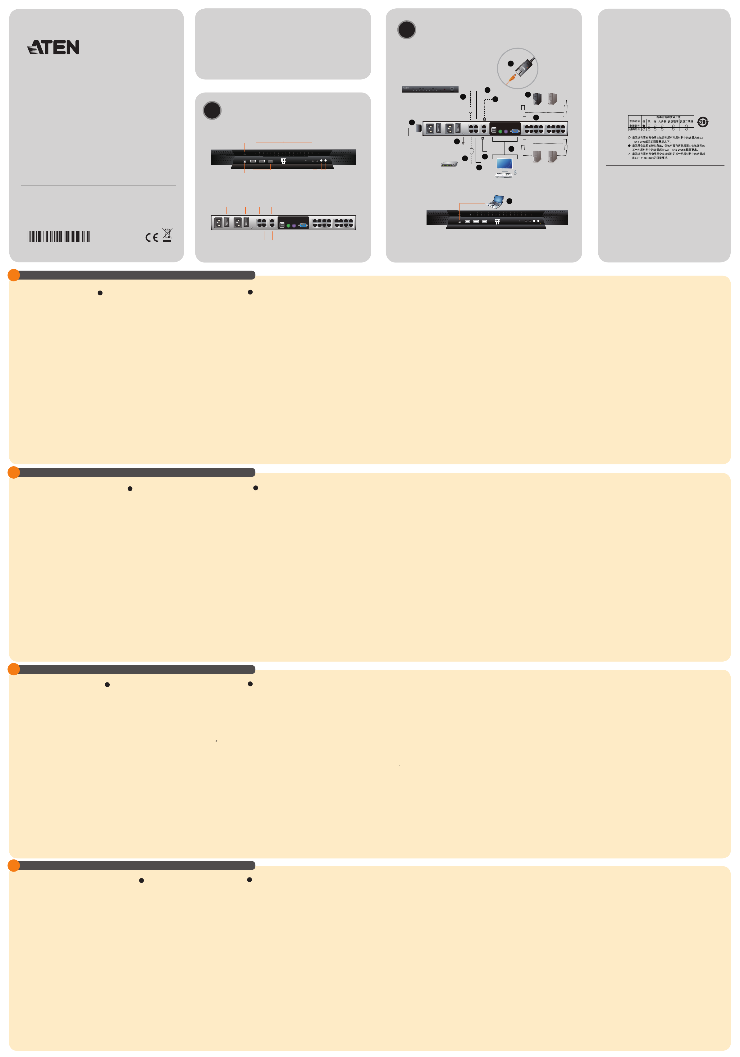
Hardware Review A
Front View
1. Power LED
2. Port LEDs
3. LAN LEDs
4. Laptop USB Console Port
5. USB Ports
6. Reset Switch
7. Audio Ports
8. Port Switching Buttons
Rear View
1. Power Sockets
2. Power Switches
3. PON Port
4. Secondary Serial Port
5. Secondary LAN Port
6. Grounding Terminal
7. Modem Port
8. Primary Serial Port
9. Primary LAN Port
10. Local Console Ports
11. KVM Ports
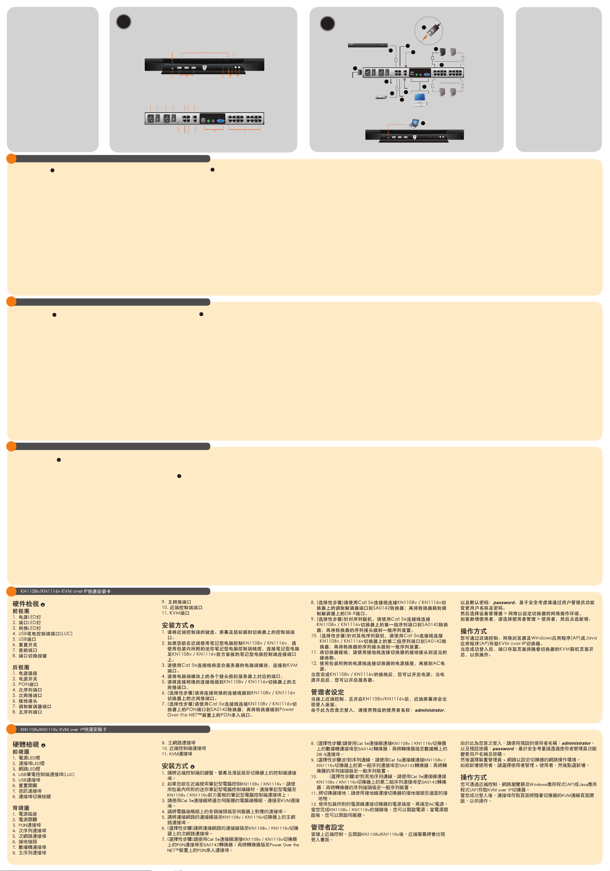
Installation B
1. Plug your Local Console’s keyboard, monitor, and mouse into
the unit’s Console Ports. Each port is color coded and marked
with an appropriate icon.
2. If you are using a laptop to control the KN1108v / KN1116v
locally, use the Laptop USB Console Cable included in the
package to connect the laptop to the KN1108v / KN1116v's
Laptop USB Console port, located on the unit's front panel.
3. Use Cat 5e cable to connect any available KVM port to a KVM
Adapter Cable.
4. Connect KVM Adapter to server.
5. Plug a cable from the LAN or WAN into the KN1108v / KN1116v
primary network interface socket.
6. (Optional) Plug another cable from the LAN or WAN into the
KN1108v / KN1116v backup (secondary) network interface
socket.
7. (Optional) Use Cat 5e cable to connect the KN1108v / KN1116v
PON port to an SA0142 Adapter. Connect the Adapter to the
PON IN port of a Power Over the NET™ unit.
8. (Optional) Use Cat 5e cable to connect the KN1108v /
KN1116v’s Modem port to an SA0142 Adapter. Then connect
SA0142 Adapter to the modem’s DB-9 port.
9. (Optional) For serial connectivity, use Cat 5e cable to connect
the KN1108v / KN1116v’s Serial 1 port to an SA0142 Adapter.
Then connect SA0142 Adapter to the serial device.
10. (Optional) For further serial connectivity, use Cat 5e cable to
connect the KN1108v / KN1116v’s secondary port to an SA0142
Adapter. Connect SA0142 Adapter to the serial device.
11. Ground the switch. Use the grounding wire to connect the
switch’s grounding terminal to a suitable grounded object.
12. Plug the power cord.
After the KN1108v / KN1116v installation, you can turn on the
power. After it is powered on, you can turn on the servers.
Administrator Setup
When the local console has been connected up and the KN1108v /
KN1116v is on, a login prompt appears on the console monitor.
Since this is the fi rst time you are logging in, use the default
Username: administrator; and the default Password: password.
For security purposes, use the User Management function to
change these to a unique Username and Password
Then, select Device Management > Network to set up the switch for
network operation.
To add users, select User Management > Users, then click Add.
Operation
KVM over IP switches can be accessed from a local console; an
internet browser; a Windows application (AP) program; and a Java
All information, documentation, firmware, software utilities, and
specifi cations contained in this package are subject to change without
prior notification by the manufacturer. Please visit our website http://
www.aten.com/download/?cid=dds for the most up-to-date versions.
application (AP) program.
After you have successfully logged in, the Port Access page comes
up with the KVM over IP switch’s KVM Connections page displayed
for operation.
Guide de démarrage rapide du KVM over IP KN1108v/KN1116v
Description de l’appareil A
Vue avant
1. Voyant d’alimentation
2. Voyants des ports
3. Voyants LAN
4. Port de console USB pour ordinateur portable
5. Ports USB
6. Bouton de réinitialisation
7. Ports audio
8. Boutons de changement de port
Vue arrière
1. Prises d'alimentation
2. Interrupteurs d’alimentation
3. Port PON
4. Port série secondaire
5. Port LAN secondaire
6. Prise de terre
7. Port modem
8. Port série principal
9. Port LAN principal
10. Ports de console locaux
11. Ports KVM
Installationn B
1. Branchez le clavier, la souris et le moniteur de la console locale
sur les ports de console de l'appareil. Chaque port est identifi é
par un code couleur et une icône correspondante.
2. Si vous utilisez un ordinateur portable pour contrôler le KN1108v
/ KN1116v localement, utilisez le mini câble de console pour
ordinateur portable fourni dans l’emballage pour connecter
l’ordinateur portable au port de console pour ordinateur portable
du KN1108v / KN1116v situé sur le panneau avant de l’appareil.
3. Utilisez un câble de catégorie 5e pour connecter un port KVM
disponible à un câble adaptateur KVM adapté au serveur que
vous installez.
4. Branchez les connecteurs du câble adaptateur KVM sur les
ports appropriés du serveur que vous installez.
5. Reliez un câble réseau LAN ou WAN au connecteur d'interface
réseau principal du KN1108v / KN1116v.
6. (Facultatif) Reliez un autre câble réseau LAN ou WAN au
connecteur d'interface réseau de secours (secondaire) du
KN1108v / KN1116v.
7. (Facultatif) Utilisez un câble de catégorie 5e pour relier le
port PON du KN1108v / KN1116v à un adaptateur SA0142.
Branchez l'adaptateur sur le port d'entrée PON (PON IN) d'un
appareil Power Over the NET™.
8. (Facultatif) Utilisez un câble de catégorie 5e pour relier le
port PON du KN1108v / KN1116v à un adaptateur SA0142.
Branchez le connecteur série de l'adaptateur sur le port DB-9
du modem.
9. (Facultatif) Pour une connexion en série, utilisez un câble de
catégorie 5e pour relier le port série 1 du KN1108v / KN1116v
à un adaptateur SA0142. Branchez le connecteur série de
l'adaptateur à un périphérique série générique.
10. (Facultatif) Pour une connexion en série supplémentaire, utilisez
un câble de catégorie 5e pour relier le port série 2 du KN1108v
/ KN1116v à un adaptateur SA0142. Branchez le connecteur
série de l'adaptateur à un périphérique série générique.
11. Reliez le commutateur à la terre. Utilisez le câble de mise
à la terre pour raccorder le terminal de mise à la terre du
commutateur à un objet correctement mis à la terre.
12. Reliez le(s) câble(s) d'alimentation fourni(s) à la prise
d'alimentation du commutateur, puis à une prise de courant CA.
Une fois le KN1108v / KN1116v câblé, vous pouvez le mettre sous
tension. Une fois qu’il est allumé, vous pouvez mettre les serveurs
sous tension.
Confi guration administrateur
Une fois que la console locale est connectée et que le KN1108v
/ KN1116v est allumé, une invite de connexion s’affi che sur le
moniteur de la console :
Lors de la première connexion, utilisez le nom d'utilisateur par
défaut administrator, et le mot de passe par défaut password.
Pour des raisons de sécurité, utilisez la fonction « User Management
» (Gestion des utilisateurs) pour les remplacer par un nom
d'utilisateur et un mot de passe uniques.
Puis, sélectionnez Device Management (Gestion des
périphériques) > Network (Réseau) pour confi gurer le commutateur
pour une utilisation en réseau.
Pour ajouter des utilisateurs, sélectionnez User Management
(Gestion des utilisateurs) > Users (Utilisateurs) puis cliquez sur
Add (Ajouter).
Fonctionnement
Vous pouvez accéder aux commutateurs KVM over IP à l’aide
d’une console locale, d'un navigateur Internet, d’un programme
d’application Windows ou d'un programme d'application Java.
Une fois que vous êtes connecté, la page Port Access (Accès aux
ports) apparaît et la page KVM Connections (Connexions KVM)
du commutateur KVM over IP est affi chée. Vous pouvez alors
commencer à l’utiliser.
KN1108v/KN1116v KVM over IP Kurzanleitung
Hardwareübersicht A
Vorderseitige Ansicht
1. LED-Betriebsanzeige
2. Port-LEDs
3. LAN-LED-Anzeigen
4. Laptop-USB-Konsolport
5. USB-Ports
6. Schalter zum Zurücksetzen
7. Audioports
8. Portumschalter-Tasten
Rückseitige Ansicht
1. Steckdosen
2. Netzschalter
3. PON-Anschluss
4. Zweiter serieller Port
5. Zweiter LAN-Port
6. Erdungsanschluss
7. Modemport
8. Erster serieller Port
9. Erster LAN-Port
10. Lokale Konsolports
11. KVM-Ports
Installation B
1. Verbinden Sie Tastatur, Monitor und Maus der lokalen Konsole
mit den Konsolports des Gerätes. Jede Buchse ist durch ein
entsprechendes Symbol sowie farblich gekennzeichnet.
2. Wenn Sie den KN1108v / KN1116v lokal über einen Laptop
steuern möchten, verwenden Sie das mitgelieferte MiniLaptop-Kabel, und verbinden Sie den Laptop mit dem Laptop-
Konsolport des KN1108v / KN1116v. Dieser befi ndet sich auf
der Vorderseite des Gerätes.
3. Verbinden Sie einen beliebigen KVM-Port mit einem KVMAdapterkabel, das für den anzuschließenden Server geeignet
ist. Verwenden Sie dazu ein Kat. 5e-Kabel.
4. Verbinden Sie den Stecker des KVM-Adapterkabels mit den
betreffenden Ports des anzuschließenden Servers.
5. Verbinden Sie ein LAN- oder WAN-Kabel mit dem ersten
Netzwerkanschluss des KN1108v / KN1116v.
6. (Optional) Verbinden Sie ein weiteres LAN- oder WAN-Kabel
mit dem zweiten (Backup-) Netzwerkanschluss des KN1108v /
KN1116v.
7. (Optional) Verwenden Sie Kat. 5e-Kabel, um den PON-Port des
KN1108v / KN1116v mit einem SA0142-Adapter zu verbinden.
Verbinden Sie anschließend den Adapter mit dem Port PON IN
eines Power Over the NET™-Gerätes.
8. (Optional) Verwenden Sie Kat. 5e-Kabel, um den
Modemanschluss des KN1108v / KN1116v mit einem SA0142-
Adapter zu verbinden. Verbinden Sie anschließend den
seriellen Anschluss des Adapters mit dem DB-9-Anschluss des
Modems.
9. (Optional) Für serielle Verbindungen verwenden Sie Kat.
5e-Kabel, um den Anschluss Serial 1 des KN1108v / KN1116v
mit einem SA0142-Adapter zu verbinden. Verbinden Sie
anschließend den seriellen Anschluss des Adapters mit einem
beliebigen seriellen Gerät.
10. (Optional) Für weitere serielle Verbindungen verwenden Sie
Kat. 5e-Kabel, um den Anschluss Serial 2 des KN1108v /
KN1116v mit einem SA0142-Adapter zu verbinden. Verbinden
Sie anschließend den seriellen Anschluss des Adapters mit
einem beliebigen seriellen Gerät.
11. Erden Sie den Switch. Verbinden Sie den Erdungsanschluss
des Gerätes mit einem geerdeten Gegenstand. Verwenden Sie
dazu das Erdungskabel.
12. Verbinden Sie das bzw. die mitgelieferte(n) Netzkabel mit der
Stromeingangsbuchse am Switch und dem Stromnetz.
Nachdem alle Kabelanschlüsse am KN1108v / KN1116v hergestellt
wurden, können Sie das Gerät einschalten. Nachdem das Gerät
eingeschaltet wurde, können Sie auch die angeschlossenen Server
einschalten.
Administrator-Einrichtung
Nachdem die lokale Konsole verbunden und der KN1108v /
KN1116v eingeschaltet wurde, erscheint ein Anmeldefenster auf
dem Konsolmonitor:
Wenn Sie sich zum ersten Mal anmelden, verwenden Sie
den vorgegebenen Benutzernamen: administrator; das
Standardkennwort lautet: password. Wir empfehlen Ihnen, den
vorgegebenen Benutzernamen sowie das Kennwort umgehend
über die Option "Benutzerverwaltung" zu ändern.
Wählen Sie anschließend „Geräteverwaltung“ > „Netzwerk“, um die
Netzwerkfunktionen für den Switch einzurichten.
Um Benutzer hinzuzufügen, wählen Sie „Benutzerverwaltung“ >
„Benutzer“ und klicken auf Hinzufügen.
Bedienung
Sie können auf die KVM over IP-Switches über die lokale Konsole,
einen Web-Browser, eine Windows-Applikation oder eine JavaApplikation zugreifen.
Nachdem Sie sich erfolgreich angemeldet haben, erscheinen die
Seite „Portzugriff“ und die Seite „KVM-Verbindung“ des Switches,
über die Sie das System bedienen können.
KN1108v/KN1116v KVM over IP Guía rápida
Presentación del hardware A
Vista frontal
1. Indicador LED de alimentación
2. Indicadores LED de los puertos
3. Indicadores LAN
4. Puerto USB de consola de computadora portátil
5. Puertos USB
6. Interruptor de reseteo
7. Puertos de audio
8. Botones de conmutación entre puertos
Vista posterior
1. Tomas eléctricas
2. Interruptores de alimentación
3. Puerto PON
4. Puerto serie secundario
5. Puerto LAN secundario
6. Toma de tierra
7. Puerto para módem
8. Puerto serie primario
9. Puerto LAN primario
10. Puertos de consola local
11. Puertos KVM
Instalación B
1. Conecte el teclado, el monitor y el mouse de la consola local a
los puertos de consola de la unidad. Cada puerto lleva el código
de color estándar, además de un icono para su identifi cación.
2. Si desea controlar el KN1108v / KN1116v localmente desde un
PC portátil, emplee el cable Miniconsola para portátiles incluido
y conecte el PC portátil al puerto para portátil del KN1108v /
KN1116v que se encuentra en el panel anterior del equipo.
3. Conecte cualquier puerto KVM disponible al cable adaptador
KVM adecuado para el servidor que vaya a instalar. Para ello,
use un cable de categoría 5e.
4. Enchufe los conectores del cable adaptador KVM a los puertos
correspondientes del servidor que quiera instalar.
5. Conecte un cable LAN o WAN al puerto de interfaz de red
principal del KN1108v / KN1116v.
6. (Opcional) Conecte otro cable LAN o WAN al puerto de interfaz
de red de respaldo (secundario) del KN1108v / KN1116v.
7. (Opcional) Utilice un cable de categoría 5e para conectar el
puerto PON del KN1108v / KN1116v a un adaptador SA0142.
Conecte el adaptador al puerto de entrada PON de una unidad
Power Over the NET™.
8. (Opcional) Utilice un cable de categoría 5e para conectar el
puerto para módem del KN1108v / KN1116v a un adaptador
SA0142. Enchufe el conector serie del adaptador al puerto
DB-9 del módem.
9. (Opcional) Para una conectividad serie, utilice un cable de
categoría 5e para conectar el puerto Serial 1 del KN1108v /
KN1116v a un adaptador SA0142. Enchufe el conector serie del
adaptador a un dispositivo serie genérico.
10. (Opcional) Para más conectividad serie, utilice un cable de
categoría 5e para conectar el puerto Serial 2 del KN1108v /
KN1116v a un adaptador SA0142. Enchufe el conector serie del
adaptador a un dispositivo serie genérico.
11. Conecte el conmutador a tierra. Conecte el terminal de tierra
del conmutador a un objeto debidamente conectado a tierra.
Para ello, emplee el conductor de tierra.
12. Conecte el/los cable(s) de alimentación incluido(s) a la entrada
de alimentación del conmutador y luego a una toma eléctrica.
Una vez conectados los cables al KN1108v / KN1116v, puede
encenderlo. A continuación, encienda los servidores.
Confi guración del administrador
Después de conectar la consola local y de encender el KN1108v /
KN1116v, aparecerá un cuadro de diálogo de inicio de sesión:
La primera vez que se conecte, especifi que el nombre de usuario
predeterminado administrator; y la contraseña predeterminada
password. Por motivos de seguridad, utilice la función
"Administración de usuarios" para cambiarlos por un nombre de
usuario y una contraseña únicos.
A continuación, seleccione "Administración de dispositivos" > "Red"
para confi gurar el conmutador para un uso en red.
Para agregar usuarios, seleccione “Administración de usuarios” >
“Usuarios” y haga clic en Agregar.
Funcionamiento
Puede acceder a los conmutadores KVM over IP mediante la
consola local, un navegador Web o un programa de aplicación
cliente de Java o de Windows.
Una vez iniciada la sesión, se abrirá la página Acceso a puerto
junto a la ventana de Conexiones KVM del conmutador KVM over
IP, donde podrá administrar los equipos.
Package Contents
1 KN1108v / KN1116v KVM Switch
2 SA0142 Serial Adapters (RJ45-F
to DB9-M; DTE to DCE)
2 Power Cords
1 Laptop USB Console Cable
1 Mounting Kit
1 Foot Pad Set (4 pcs.)
1 User Instructions
Hardware Review
A
Front View
Rear View
1 3
4 87
5 6
2 3 41 21
5
B
2
Installation
PN0108
11
Modem
4
7
11
10
6
5
8
9
4
3
1
Important Notice
Considering environmental protection,
ATEN does not provide a fully printed
user manual for this product. If the
information contained in the Quick Start
Guide is not enough for you to confi gure
and operate your product, please visit
our website w w w.aten. com, and
download the full user manual.
Online Registration
http://eservice.aten.com
Technical Phone Support
International:
886-2-86926959
Guida rapida KN1108v/KN1116v KVM over IP
Hardware A
Vista anteriore
1. LED d’alimentazione
2. LED delle porte
3. LED LAN
4. Porta USB di collegamento alla console laptop
5. Porte USB
6. Interruttore di ripristino
7. Porte audio
8. Pulsanti del cambiamento di porta
Vista posteriore
1. Prese per l’alimentazione
2. Interruttori di alimentazione
3. Porta PON
4. Porta seriale secondaria
5. Porta LAN secondaria
6. Terminale di messa a terra
7. Porta del modem
8. Porta seriale primaria
9. Porta LAN primaria
10. Porte console locale
11. Porte KVM
6
7 8
9
10
11
Installazione B
1. Inserire gli spinotti di tastiera, mouse e monitor della
console locale nelle porte console dell'unità. Ogni porta è
contrassegnata da un colore e da un’icona appropriata.
2. Nel caso in cui si impieghi un portatile per controllare
localmente il KN1108v / KN1116v, utilizzare il cavo per console
mini laptop in dotazione per collegare il portatile alla porta di
collegamento della console del dispositivo, situata sul pannello
anteriore del KN1108v / KN1116v.
3. Utilizzare un cavo Cat 5e per collegare qualsiasi porta KVM
disponibile a un cavo adattatore KVM adeguato al server che si
sta confi gurando.
4. Inserire i connettori del cavo dell’adattatore KVM nelle porte
corrispondenti del server che si sta confi gurando.
5. Inserire un cavo della LAN o WAN nella presa di rete primaria
del KN1108v / KN1116v.
6. (Opzionale) Inserire un altro cavo della LAN o WAN nella presa
di rete secondaria del KN1108v / KN1116v.
7. (Opzionale) Utilizzare un cavo Cat. 5e per connettere la
porta PON del KN1108v / KN1116v ad un adattatore SA0142.
Connettere l’adattatore alla porta PON IN di un’unità Power
Over the NET™.
8. (Opzionale) Utilizzare il cavo Cat. 5e per connettere la porta
2
del modem del KN1108v / KN1116v ad un adattatore SA0142.
Collegare il connettore seriale dell'adattatore alla porta DB-9 del
modem.
9. (Opzionale) Per i collegamenti seriali, utilizzare il cavo Cat.
5e per connettere la porta seriale 1 del KN1108v / KN1116v
a un adattatore SA0142. Collegare il connettore seriale
dell'adattatore a un dispositivo seriale generico.
10. (Opzionale) Per altri collegamenti seriali, utilizzare il cavo Cat.
5e per connettere la porta seriale 2 del KN1108v / KN1116v
a un adattatore SA0142. Collegare il connettore seriale
dell'adattatore a un dispositivo seriale generico.
11. Mettere a terra il dispositivo. Utilizzare il fi lo di messa a terra
per connettere il terminale di messa a terra dello switch a un
oggetto dotato di adeguata messa a terra.
12. Inserire la spina del/dei cavo/i di alimentazione fornito/i insieme
a questa confezione nella presa di alimentazione dello switch e
poi all’alimentazione CA.
Una volta collegato il KN1108v / KN1116v, accenderlo. Una volta
acceso il dispositivo è possibile accendere i server.
Confi gurazione da parte
dell’amministratore
Dopo aver connesso la console locale e acceso il KN1108v /
North America:
1-888-999-ATEN Ext: 4988
United Kingdom:
44-8-4481-58923
KN1116v, sul monitor della console apparirà una fi nestra di login.
Come prima volta in cui si esegue il login, utilizzare il Nome utente
predefi nito: administrator e la password predefi nita: password.
Per ragioni di sicurezza, utilizzare la funzione Gestione utenti per
modifi care nome utente e password
Selezionare Gestione dispositivo --> Rete per impostare lo switch
per il funzionamento in rete.
Per aggiungere utenti, selezionare Gestione utenti -> Utenti e fare
clic su Aggiungi.
Funzionamento
Agli switch KVM over IP è possibile accedere da una console
locale, da un browser Internet e da un’applicazione (AP) Java o
Windows.
Una volta effettuato il login, si aprirà la pagina Accesso alla porta e
verrà mostrata la pagina Connessioni KVM per lo switch KVM over
IP.
KN1108v/KN1116vKVMoverIPクイックスタートガイド
製品各部名称A
フロントパネル
1. 電源LED
2. ポートLED
3. LANLED
4.ラップトップUSBコンソールポート
5. USBポート
6. リセットスイッチ
7. オーディオポート
8. ポート切替ボタン
リアパネル
1. 電源ソケット
2. 電源スイッチ
3. PONポート
4.セカンドシリアルポート
5. セカンドLANポート
6. 接地ターミナル
7. モデムポート
8. プライマリシリアルポート
9. プライマリLANポート
10.ローカルコンソールポート
11.KVMポート
KN1108v/KN1116v KVM over IP 퀵 스타트 가이드
セットアップB
1.ローカルコンソール用のキーボード・モニター・マウスを本製品の
コンソールポートに接続してください。各ポートは色分けされてお
り、アイコンが表示されています。
2.ノートパソコンを使ってKN1108v/KN1116vをローカルから操
作する場合は、ノートパソコンとKN1108v/KN1116vフロント
パネルにあるラップトップコンソールポートを、製品パッケージに
同梱されているミニラップトップコンソールケーブルで接続してく
ださい。
3.カテゴリ5eケーブルを使用して、任意のKVMポートと、今からセ
ットアップするサーバーに合ったコンピューターモジュールとを接
続してください。
4.コンピューターモジュールのコネクターを、セットアップするサー
バーの適切なポートにそれぞれ接続してください。
5.LANまたはWANからのケーブルをKN1108v/KN1116vのプライ
マリネットワークインターフェースソケットに接続してください。
6.(オプション)LANまたはWANからの別のケーブルをKN1108v/
KN1116vのバックアップ(セカンド)ネットワークインターフェ
ースソケットに接続してください。
7.(オプション)カテゴリ5eケーブルを使用して、KN1108v/
KN1116vのPONポートとSA0142アダプターを接続してくださ
い。それからアダプターをPowerOvertheNET™製品のPONIN
ポートに接続してください。
8.(オプション)カテゴリ5eケーブルを使用して、KN1108v/
KN1116vのモデムポートとSA0142アダプターを接続してく
ださい。それからアダプターのシリアルコネクターをモデムの
D-sub9ピンポートに接続してください。
9.(オプション)シリアル接続を使用する場合、カテゴリ5eケー
ブルを使用して、KN1108v/KN1116vのシリアルポート1と
SA0142アダプターを接続してください。それからアダプターの
シリアルコネクターを一般的なシリアルデバイスに接続してくだ
さい。
10. (オプション)さらにシリアル接続を行う場合は、カテゴリ
5eケーブルを使用して、KN1108v/KN1116vのシリアルポー
ト2とSA0142を接続してください。それからアダプターのシリア
ルコネクターを一般的なシリアルデバイスに接続してください。
11. 本製品に接地を行ってください。接地線を使用して、本製品の接
地ターミナルと適切な接地物を接続してください。
12. 本製品に同梱されている電源コードを本製品の電源ソケットに接
続した後、AC電源に接続してください。
KN1108v/KN1116vのケーブル接続が完了したら、本製品の電源
を入れてください。本製品の電源が入ったら、サーバーの電源を入れ
てください。
アドミニストレーター用セットアップ
ローカルコンソールが接続され、KN1108v/KN1116vの電源が入
ったら、コンソールモニターにログインプロンプトが表示されます。
初回ログイン時には、デフォルトのユーザーネームである
www.aten.com
administrator
力してください。セキュリティの面から、ユーザー管理機能を使用
して、独自のユーザーネームとパスワードに変更してください。
その後、本製品のネットワーク操作をセットアップするには、デバ
イス管理→ネットワークを選択してください。
ユーザーを追加するには、ユーザー管理→ユーザーを選択してか
ら、追加をクリックしてください。
およびデフォルトのパスワードである
password
を入
操作方法
KVMoverIPスイッチは、ローカルコンソール、インターネットブ
ラウザ、Windowsアプリケーションプログラム(AP)およびJavaア
プリケーションプログラム(AP)からアクセスすることができま
す。
ログイン成功後、ポートアクセスページがKVMoverIPスイッチの
KVM接続ページとともに表示され、操作ができるようになります。
하드웨어 리뷰 A
전면
1. 전원 LED
2. 포트 LED
3. LAN LEDs
4. 랩탑 USB 콘솔 포트
5. USB 포트
6. 리셋 스위치
7. 오디오 포트
8. 포트 스위칭 버튼
후면
1. 전원 소켓
2. 전원 스위치
3. PON 포트
4. 보조 시리얼 포트
5. 보조 LAN 포트
6. 접지 터미널
7. 모뎀 포트
8. 기본 시리얼 포트
9. 기본 LAN 포트
10. 로컬 콘솔 포트
11. KVM 포트
설치 B
1. 로컬 콘솔 키보드, 모니터 그리고 마우스를 장치의 콘솔
포트에 연결합니다. 각 포트는 색깔 코드로 적절한 아이콘으로
표시됩니다.
2. 사용자가 랩탑을 사용하여 지역적으로 KN1108v / KN1116v을
제어하려는 경우, 패키지에 포함된 미니 랩탑 콘솔 케이블을
사용하여 랩탑과 KN1108v / KN1116v의 전면 패널에 있는 랩탑
콘솔 포트에 연결하십시오.
3. 설치하는 서버에 적합한 KVM 어댑터 케이블을 설치 후 KVM
포트와 Cat 5e 케이블 을 이용하여 연결할 수 있습니다.
4. KVM 어댑터 케이블에 있는 커넥터를 설치하려는 서버의 적절한
포트에 연결합니다.
5. LAN 또는 WAN케이블을 KN1108v / KN1116v 기본 네트워크
인터페이스 소켓에 연결합니다.
6. (선택사항) LAN 또는 WAN의 또 다른 케이블로 KN1108v
/ KN1116v 의 백업(보조) 네트워크 인터페이스 소켓에
연결합니다.
7. (선택사항) Cat 5e 케이블을 이용하여KN1108v / KN1116v PON
포트를 SA0142 어댑터에 연결합니다. 어댑터를 Power Over the
NET™ 장치의 PON IN 포트에 연결합니다.
8. (선택사항) Cat 5e케이블을 이용하여 KN1108v / KN1116v의
모뎀 포트를 SA0142 어댑터에 연결합니다. 어댑터의 시리얼
커넥터를 모뎀의 DB-9 포트에 연결합니다.
9. (선택사항) 시리얼 연결 시, Cat 5e케이블을 이용하여KN1108v
/ KN1116v의 시리얼 1 포트를 SA0142 어댑터에 연결합니다.
어댑터의 시리얼 커넥터는 일반적인 시리얼 장치에 연결합니다.
10. (선택사항) 더 많은 시리얼 연결을 위해, Cat 5e 케이블을
이용하여 KN1108v / KN1116v의 시리얼 2 포트를 SA0142
어댑터에 연결합니다. 어댑터의 시리얼 커넥터 는 일반적인
시리얼 장치에 연결합니다.
11. 스위치를 접지하기 위해 접지 와이어로 스위치의 접지 터미널을
적절한 접지 물체와 연결합니다..
12. AC의 전원 소스에 패키지에 포함되어 있는 전원 코드를
스위치의 전원 소켓에 연결합니다.
KN1108v / KN1116v의 모든 케이블 연결이 끝난 후 전원을 켭니다.
전원이 들어오면 그 후에 서버의 전원을 켭니다.
관리자 설정
로컬 콘솔이 연결되고KN1108v / KN1116v 이 켜져 있는 상태에는
콘솔 모니터에 로그인 창이 나타납니다.
처음 로그인 하는 것이기 때문에 기본 사용자 이름:
과 기본 비밀번호:
사용자 관리 기능을 위해 독특한 사용자이름과 비밀번호로 바꾸시기
바랍니다.
그런 후에, 장비 관리>네트워크 운영을 위한 설정을 선택하십시오
사용자를 추가하기 위해, 사용자 관리 > 사용자를 선택 후 추가 를
선택합니다.
password
. 를 사용합니다. 보안 목적으로,
administrator
;
운영
KVM over IP 스위치는 로컬 콘솔에서 인터넷 브라우저, 윈도우
어플리케이션(AP), 자바 어플리케이션 (AP)프로그램 접속이
가능합니다.
성공적으로 로그 인 후 운영을 위해 KVM over IP 스위치의 KVM
연결 페이지와 포트 접속 페이지가 디스플레이 됩니다.
 Loading...