

KVM Over the NET™
KN1000
User Manual
www.aten.com

KN1000 User Manual
FCC Information
This is an FCC Class A product. In a domestic environment this product may
cause radio interference in which case the user may be required to take
adequate measures.
This equipment has been tested and found to comply with the limits for a Class
A digital device, pursuant to Part 15 of the FCC Rules. These limits are
designed to provide reasonable protection against harmful interference when
the equipment is operated in a commercial environment. This equipment
generates, uses and can radiate radio frequency energy and, if not installed and
used in accordance with the instruction manual, may cause harmful
interference to radio communications. Operation of this equipment in a
residential area is likely to cause harmful interference in which case the user
will be required to correct the interference at his own expense.
RoHS
This product is RoHS compliant.
SJ/T 11364-2006
The following contains information that relates to China.
ii

User Information
Online Registration
Be sure to register your product at our online support center:
International http://support.aten.com
North America http://www.aten-usa.com/product_registration
Telephone Support
For telephone support, call this number:
International 886-2-8692-6959
China 86-10-5255-0110
Japan 81-3-5615-5811
Korea 82-2-467-6789
North America 1-888-999-ATEN ext 4988
United Kingdom 44-8-4481-58923
KN1000 User Manual
User Notice
All information, documentation, and specifications contained in this manual
are subject to change without prior notification by the manufacturer. The
manufacturer makes no representations or warranties, either expressed or
implied, with respect to the contents hereof and specifically disclaims any
warranties as to merchantability or fitness for any particular purpose. Any of
the manufacturer's software described in this manual is sold or licensed as is.
Should the programs prove defective following their purchase, the buyer (and
not the manufacturer, its distributor, or its dealer), assumes the entire cost of all
necessary servicing, repair and any incidental or consequential damages
resulting from any defect in the software.
The manufacturer of this system is not responsible for any radio and/or TV
interference caused by unauthorized modifications to this device. It is the
responsibility of the user to correct such interference.
The manufacturer is not responsible for any damage incurred in the operation
of this system if the correct operational voltage setting was not selected prior
to operation. PLEASE VERIFY THAT THE VOLTAGE SETTING IS
CORRECT BEFORE USE.
iii

KN1000 User Manual
Copyright © 2011–2012 ATEN® International Co., Ltd.
Manual Part No. PAPE-0339-AX2G
Firmware Version: v1.0.066
Manual Date: 2012-03-13
Altusen and the Altusen logo are registered trademarks of ATEN International Co., Ltd. All rights re-
served. All other brand names and trademarks are the registered property of their respective owners.
Package Contents
The basic KN1000 package consists of:
1 KN1000
2 Custom KVM Cable Sets
1 Custom Console Cable Set
1 USB 2.0 Virtual Media Cable
1 Power Adapter
1 Outlet Power Cord
1 Rack Mount Kit
1 Software CD
1 User Instructions*
Check to make sure that all of the components are present and in good order.
If anything is missing, or was damaged in shipping, contact your dealer.
Read this manual thoroughly and follow the installation and operation
procedures carefully to prevent any damage to the switch or to any other
devices on the KN1000 installation.
* Features may have been added to the KN1000 since this manual was printed.
Please visit our website to download the most up-to-date version.
iv

KN1000 User Manual
Contents
FCC Information . . . . . . . . . . . . . . . . . . . . . . . . . . . . . . . . . . . . . . . . . . . . .ii
SJ/T 11364-2006. . . . . . . . . . . . . . . . . . . . . . . . . . . . . . . . . . . . . . . . . . . . .ii
User Information . . . . . . . . . . . . . . . . . . . . . . . . . . . . . . . . . . . . . . . . . . . . .iii
Online Registration . . . . . . . . . . . . . . . . . . . . . . . . . . . . . . . . . . . . . . . .iii
Telephone Support . . . . . . . . . . . . . . . . . . . . . . . . . . . . . . . . . . . . . . . .iii
User Notice . . . . . . . . . . . . . . . . . . . . . . . . . . . . . . . . . . . . . . . . . . . . . .iii
Package Contents. . . . . . . . . . . . . . . . . . . . . . . . . . . . . . . . . . . . . . . . . . . iv
About This Manual . . . . . . . . . . . . . . . . . . . . . . . . . . . . . . . . . . . . . . . . . . .x
Conventions . . . . . . . . . . . . . . . . . . . . . . . . . . . . . . . . . . . . . . . . . . . . xi
Product Information. . . . . . . . . . . . . . . . . . . . . . . . . . . . . . . . . . . . . . . . . . xi
Terminology. . . . . . . . . . . . . . . . . . . . . . . . . . . . . . . . . . . . . . . . . . . . . xii
Chapter 1.Introduction
Overview. . . . . . . . . . . . . . . . . . . . . . . . . . . . . . . . . . . . . . . . . . . . . . . . . . .1
Features and Benefits. . . . . . . . . . . . . . . . . . . . . . . . . . . . . . . . . . . . . . . . .3
System Requirements. . . . . . . . . . . . . . . . . . . . . . . . . . . . . . . . . . . . . . . . .6
Remote User Computers. . . . . . . . . . . . . . . . . . . . . . . . . . . . . . . . . . . .6
Servers . . . . . . . . . . . . . . . . . . . . . . . . . . . . . . . . . . . . . . . . . . . . . . . . .6
Cables. . . . . . . . . . . . . . . . . . . . . . . . . . . . . . . . . . . . . . . . . . . . . . . . . .7
Video. . . . . . . . . . . . . . . . . . . . . . . . . . . . . . . . . . . . . . . . . . . . . . . . . . . 8
Operating Systems . . . . . . . . . . . . . . . . . . . . . . . . . . . . . . . . . . . . . . . .8
Browsers . . . . . . . . . . . . . . . . . . . . . . . . . . . . . . . . . . . . . . . . . . . . . . . .9
Components . . . . . . . . . . . . . . . . . . . . . . . . . . . . . . . . . . . . . . . . . . . . . . .10
Front View. . . . . . . . . . . . . . . . . . . . . . . . . . . . . . . . . . . . . . . . . . . . . .10
Rear View . . . . . . . . . . . . . . . . . . . . . . . . . . . . . . . . . . . . . . . . . . . . . .11
Custom KVM Cables. . . . . . . . . . . . . . . . . . . . . . . . . . . . . . . . . . . . . .12
Custom Console Cable . . . . . . . . . . . . . . . . . . . . . . . . . . . . . . . . . . . .12
Chapter 2.Hardware Setup
Mounting . . . . . . . . . . . . . . . . . . . . . . . . . . . . . . . . . . . . . . . . . . . . . . . . . .13
Rack Mounting . . . . . . . . . . . . . . . . . . . . . . . . . . . . . . . . . . . . . . . . . .13
DIN Rail Mounting. . . . . . . . . . . . . . . . . . . . . . . . . . . . . . . . . . . . . . . .15
Installation. . . . . . . . . . . . . . . . . . . . . . . . . . . . . . . . . . . . . . . . . . . . . . . . .16
Chapter 3.Browser Login
Logging In . . . . . . . . . . . . . . . . . . . . . . . . . . . . . . . . . . . . . . . . . . . . . . . . .19
Main Webpage Elements . . . . . . . . . . . . . . . . . . . . . . . . . . . . . . . . . . . . .22
Utility Icons . . . . . . . . . . . . . . . . . . . . . . . . . . . . . . . . . . . . . . . . . . . . .22
Administrative Function Icons . . . . . . . . . . . . . . . . . . . . . . . . . . . . . . .22
Remote Console Preview . . . . . . . . . . . . . . . . . . . . . . . . . . . . . . . . . .23
Exit Macro . . . . . . . . . . . . . . . . . . . . . . . . . . . . . . . . . . . . . . . . . . . . . .24
Telnet/SSH Viewer . . . . . . . . . . . . . . . . . . . . . . . . . . . . . . . . . . . . . . .24
Managing Power. . . . . . . . . . . . . . . . . . . . . . . . . . . . . . . . . . . . . . . . . . . .25
Power Management . . . . . . . . . . . . . . . . . . . . . . . . . . . . . . . . . . . . . .26
Schedule . . . . . . . . . . . . . . . . . . . . . . . . . . . . . . . . . . . . . . . . . . . . . . . 28
Auto Ping. . . . . . . . . . . . . . . . . . . . . . . . . . . . . . . . . . . . . . . . . . . . . . .30
v

KN1000 User Manual
PON Port Setting. . . . . . . . . . . . . . . . . . . . . . . . . . . . . . . . . . . . . . . . .31
PON Device. . . . . . . . . . . . . . . . . . . . . . . . . . . . . . . . . . . . . . . . . . 31
Enable 2-Wire RS232 . . . . . . . . . . . . . . . . . . . . . . . . . . . . . . . . . .31
User Preferences . . . . . . . . . . . . . . . . . . . . . . . . . . . . . . . . . . . . . . . . . . .33
Chapter 4.Administration
Introduction. . . . . . . . . . . . . . . . . . . . . . . . . . . . . . . . . . . . . . . . . . . . . . . . 35
Device Information . . . . . . . . . . . . . . . . . . . . . . . . . . . . . . . . . . . . . . . . . .36
Network. . . . . . . . . . . . . . . . . . . . . . . . . . . . . . . . . . . . . . . . . . . . . . . . . . .37
Service Ports. . . . . . . . . . . . . . . . . . . . . . . . . . . . . . . . . . . . . . . . . . . .37
IP Address. . . . . . . . . . . . . . . . . . . . . . . . . . . . . . . . . . . . . . . . . . . . . . 38
DNS Server. . . . . . . . . . . . . . . . . . . . . . . . . . . . . . . . . . . . . . . . . . . . . 39
Network Transfer Rate . . . . . . . . . . . . . . . . . . . . . . . . . . . . . . . . . . . .39
Finishing Up . . . . . . . . . . . . . . . . . . . . . . . . . . . . . . . . . . . . . . . . . . . .39
ANMS . . . . . . . . . . . . . . . . . . . . . . . . . . . . . . . . . . . . . . . . . . . . . . . . . . . .40
IP Installer. . . . . . . . . . . . . . . . . . . . . . . . . . . . . . . . . . . . . . . . . . . . . . 40
SMTP Settings . . . . . . . . . . . . . . . . . . . . . . . . . . . . . . . . . . . . . . . . . .41
Log Server. . . . . . . . . . . . . . . . . . . . . . . . . . . . . . . . . . . . . . . . . . . . . . 42
SNMP Server . . . . . . . . . . . . . . . . . . . . . . . . . . . . . . . . . . . . . . . . . . . 42
Syslog Server . . . . . . . . . . . . . . . . . . . . . . . . . . . . . . . . . . . . . . . . . . .43
DDNS . . . . . . . . . . . . . . . . . . . . . . . . . . . . . . . . . . . . . . . . . . . . . . . . .43
Disable Local Authentication. . . . . . . . . . . . . . . . . . . . . . . . . . . . . . . . 44
RADIUS Settings. . . . . . . . . . . . . . . . . . . . . . . . . . . . . . . . . . . . . . . . .44
RADIUS Examples . . . . . . . . . . . . . . . . . . . . . . . . . . . . . . . . . . . . . . .45
CC Management Settings. . . . . . . . . . . . . . . . . . . . . . . . . . . . . . . . . . 46
LDAP Settings. . . . . . . . . . . . . . . . . . . . . . . . . . . . . . . . . . . . . . . . . . .46
Security. . . . . . . . . . . . . . . . . . . . . . . . . . . . . . . . . . . . . . . . . . . . . . . . . . . 48
User Station Filters . . . . . . . . . . . . . . . . . . . . . . . . . . . . . . . . . . . . . . .48
IP Filter / MAC Filter Conflict. . . . . . . . . . . . . . . . . . . . . . . . . . . . . 49
Modifying Filters . . . . . . . . . . . . . . . . . . . . . . . . . . . . . . . . . . . . . . 50
Deleting Filters . . . . . . . . . . . . . . . . . . . . . . . . . . . . . . . . . . . . . . .50
Login String. . . . . . . . . . . . . . . . . . . . . . . . . . . . . . . . . . . . . . . . . . . . . 50
Account Policy. . . . . . . . . . . . . . . . . . . . . . . . . . . . . . . . . . . . . . . . . . .51
Login Failures . . . . . . . . . . . . . . . . . . . . . . . . . . . . . . . . . . . . . . . . . . .52
Encryption. . . . . . . . . . . . . . . . . . . . . . . . . . . . . . . . . . . . . . . . . . . . . .53
Virtual Media. . . . . . . . . . . . . . . . . . . . . . . . . . . . . . . . . . . . . . . . . . . .54
Private Certificate . . . . . . . . . . . . . . . . . . . . . . . . . . . . . . . . . . . . . . . .55
Generating a Self-Signed Certificate. . . . . . . . . . . . . . . . . . . . . . .55
Obtaining a CA Signed SSL Server Certificate. . . . . . . . . . . . . . .55
Importing the Private Certificate . . . . . . . . . . . . . . . . . . . . . . . . . .55
Others . . . . . . . . . . . . . . . . . . . . . . . . . . . . . . . . . . . . . . . . . . . . . . . . .56
User Management . . . . . . . . . . . . . . . . . . . . . . . . . . . . . . . . . . . . . . . . . .57
Console Management. . . . . . . . . . . . . . . . . . . . . . . . . . . . . . . . . . . . . . . .59
Serial Console. . . . . . . . . . . . . . . . . . . . . . . . . . . . . . . . . . . . . . . . . . .59
Port Property Settings. . . . . . . . . . . . . . . . . . . . . . . . . . . . . . . . . .60
OOBC . . . . . . . . . . . . . . . . . . . . . . . . . . . . . . . . . . . . . . . . . . . . . . . . . 62
Enable Dial Back. . . . . . . . . . . . . . . . . . . . . . . . . . . . . . . . . . . . . .62
vi

KN1000 User Manual
Sessions . . . . . . . . . . . . . . . . . . . . . . . . . . . . . . . . . . . . . . . . . . . . . . . . . .65
Customization . . . . . . . . . . . . . . . . . . . . . . . . . . . . . . . . . . . . . . . . . . . . . .66
Date/Time . . . . . . . . . . . . . . . . . . . . . . . . . . . . . . . . . . . . . . . . . . . . . . . . .68
Time Zone. . . . . . . . . . . . . . . . . . . . . . . . . . . . . . . . . . . . . . . . . . . . . .68
Date. . . . . . . . . . . . . . . . . . . . . . . . . . . . . . . . . . . . . . . . . . . . . . . . . . .69
Network Time . . . . . . . . . . . . . . . . . . . . . . . . . . . . . . . . . . . . . . . . . . .69
Maintenance . . . . . . . . . . . . . . . . . . . . . . . . . . . . . . . . . . . . . . . . . . . . . . .70
Firmware Upgrade. . . . . . . . . . . . . . . . . . . . . . . . . . . . . . . . . . . . . . . . 70
Backup . . . . . . . . . . . . . . . . . . . . . . . . . . . . . . . . . . . . . . . . . . . . . . . .71
Restore . . . . . . . . . . . . . . . . . . . . . . . . . . . . . . . . . . . . . . . . . . . . . . . .72
Chapter 5.The WinClient Viewer
Starting Up . . . . . . . . . . . . . . . . . . . . . . . . . . . . . . . . . . . . . . . . . . . . . . . .73
Navigation. . . . . . . . . . . . . . . . . . . . . . . . . . . . . . . . . . . . . . . . . . . . . . . . .74
The WinClient Control Panel. . . . . . . . . . . . . . . . . . . . . . . . . . . . . . . . . . .75
Control Panel Functions . . . . . . . . . . . . . . . . . . . . . . . . . . . . . . . . . . .77
Macros. . . . . . . . . . . . . . . . . . . . . . . . . . . . . . . . . . . . . . . . . . . . . . . . .80
Hotkeys . . . . . . . . . . . . . . . . . . . . . . . . . . . . . . . . . . . . . . . . . . . . .80
System Macros . . . . . . . . . . . . . . . . . . . . . . . . . . . . . . . . . . . . . . .86
Video Settings. . . . . . . . . . . . . . . . . . . . . . . . . . . . . . . . . . . . . . . . . . .89
The Message Board . . . . . . . . . . . . . . . . . . . . . . . . . . . . . . . . . . . . . .92
The Button Bar. . . . . . . . . . . . . . . . . . . . . . . . . . . . . . . . . . . . . . . .92
Message Display Panel. . . . . . . . . . . . . . . . . . . . . . . . . . . . . . . . .93
Compose Panel. . . . . . . . . . . . . . . . . . . . . . . . . . . . . . . . . . . . . . .93
User List Panel . . . . . . . . . . . . . . . . . . . . . . . . . . . . . . . . . . . . . . .93
Virtual Media . . . . . . . . . . . . . . . . . . . . . . . . . . . . . . . . . . . . . . . . . . . .94
Windows Vista / 7 . . . . . . . . . . . . . . . . . . . . . . . . . . . . . . . . . . . . .94
Virtual Media Icons . . . . . . . . . . . . . . . . . . . . . . . . . . . . . . . . . . . .94
Zoom. . . . . . . . . . . . . . . . . . . . . . . . . . . . . . . . . . . . . . . . . . . . . . . . . .99
The On-Screen Keyboard . . . . . . . . . . . . . . . . . . . . . . . . . . . . . . . . .100
Mouse Pointer Type . . . . . . . . . . . . . . . . . . . . . . . . . . . . . . . . . . . . .102
Mouse DynaSync Mode . . . . . . . . . . . . . . . . . . . . . . . . . . . . . . . . . .102
Automatic Mouse Synchronization (DynaSync). . . . . . . . . . . . . .102
Manual Mouse Synchronization. . . . . . . . . . . . . . . . . . . . . . . . . .103
Control Panel Configuration . . . . . . . . . . . . . . . . . . . . . . . . . . . . . . .104
Chapter 6.The JavaClient Viewer
Introduction . . . . . . . . . . . . . . . . . . . . . . . . . . . . . . . . . . . . . . . . . . . . . . .107
Navigation. . . . . . . . . . . . . . . . . . . . . . . . . . . . . . . . . . . . . . . . . . . . . . . .108
The JavaClient Control Panel . . . . . . . . . . . . . . . . . . . . . . . . . . . . . . . . .109
Control Panel Functions . . . . . . . . . . . . . . . . . . . . . . . . . . . . . . . . . .111
Macros. . . . . . . . . . . . . . . . . . . . . . . . . . . . . . . . . . . . . . . . . . . . . . . .113
Hotkeys . . . . . . . . . . . . . . . . . . . . . . . . . . . . . . . . . . . . . . . . . . . .113
System Macros . . . . . . . . . . . . . . . . . . . . . . . . . . . . . . . . . . . . . .114
Search . . . . . . . . . . . . . . . . . . . . . . . . . . . . . . . . . . . . . . . . . . . . .115
Video Settings. . . . . . . . . . . . . . . . . . . . . . . . . . . . . . . . . . . . . . . . . .115
Message Board. . . . . . . . . . . . . . . . . . . . . . . . . . . . . . . . . . . . . . . . .116
vii

KN1000 User Manual
Virtual Media. . . . . . . . . . . . . . . . . . . . . . . . . . . . . . . . . . . . . . . . . . .118
Zoom. . . . . . . . . . . . . . . . . . . . . . . . . . . . . . . . . . . . . . . . . . . . . . . . .118
The On-Screen Keyboard. . . . . . . . . . . . . . . . . . . . . . . . . . . . . . . . . 119
Mouse Pointer Type . . . . . . . . . . . . . . . . . . . . . . . . . . . . . . . . . . . . .119
Mouse DynaSync Mode . . . . . . . . . . . . . . . . . . . . . . . . . . . . . . . . . .120
Control Panel Configuration . . . . . . . . . . . . . . . . . . . . . . . . . . . . . . .120
Chapter 7.The Log File
The Log File Screen . . . . . . . . . . . . . . . . . . . . . . . . . . . . . . . . . . . . . . . .121
Chapter 8.The Log Server
Installation. . . . . . . . . . . . . . . . . . . . . . . . . . . . . . . . . . . . . . . . . . . . . . . .123
Starting Up . . . . . . . . . . . . . . . . . . . . . . . . . . . . . . . . . . . . . . . . . . . . . . .124
The Menu Bar. . . . . . . . . . . . . . . . . . . . . . . . . . . . . . . . . . . . . . . . . . . . . 125
Configure. . . . . . . . . . . . . . . . . . . . . . . . . . . . . . . . . . . . . . . . . . . . . .125
Events. . . . . . . . . . . . . . . . . . . . . . . . . . . . . . . . . . . . . . . . . . . . . . . .126
Search. . . . . . . . . . . . . . . . . . . . . . . . . . . . . . . . . . . . . . . . . . . . .126
Maintenance . . . . . . . . . . . . . . . . . . . . . . . . . . . . . . . . . . . . . . . . 127
Options . . . . . . . . . . . . . . . . . . . . . . . . . . . . . . . . . . . . . . . . . . . . . . . 128
Help. . . . . . . . . . . . . . . . . . . . . . . . . . . . . . . . . . . . . . . . . . . . . . . . . .128
The Log Server Main Screen . . . . . . . . . . . . . . . . . . . . . . . . . . . . . . . . .129
Overview. . . . . . . . . . . . . . . . . . . . . . . . . . . . . . . . . . . . . . . . . . . . . . 129
The List Panel. . . . . . . . . . . . . . . . . . . . . . . . . . . . . . . . . . . . . . . . . .130
The Tick Panel . . . . . . . . . . . . . . . . . . . . . . . . . . . . . . . . . . . . . . . . .130
Chapter 9.AP Operation
Introduction. . . . . . . . . . . . . . . . . . . . . . . . . . . . . . . . . . . . . . . . . . . . . . . 131
The Windows Client AP . . . . . . . . . . . . . . . . . . . . . . . . . . . . . . . . . . . . . 131
Installation. . . . . . . . . . . . . . . . . . . . . . . . . . . . . . . . . . . . . . . . . . . . . 131
Starting Up . . . . . . . . . . . . . . . . . . . . . . . . . . . . . . . . . . . . . . . . . . . .132
The Windows Client Connection Screen. . . . . . . . . . . . . . . . . . . . . . 133
Logging In . . . . . . . . . . . . . . . . . . . . . . . . . . . . . . . . . . . . . . . . . . . . . 134
The Administrator Utility . . . . . . . . . . . . . . . . . . . . . . . . . . . . . . . . . . . . . 136
Device Information . . . . . . . . . . . . . . . . . . . . . . . . . . . . . . . . . . . . . .136
Network. . . . . . . . . . . . . . . . . . . . . . . . . . . . . . . . . . . . . . . . . . . . . . . 137
ANMS . . . . . . . . . . . . . . . . . . . . . . . . . . . . . . . . . . . . . . . . . . . . . . . . 138
Security. . . . . . . . . . . . . . . . . . . . . . . . . . . . . . . . . . . . . . . . . . . . . . .139
User Management. . . . . . . . . . . . . . . . . . . . . . . . . . . . . . . . . . . . . . .140
Console Management. . . . . . . . . . . . . . . . . . . . . . . . . . . . . . . . . . . .141
Serial Console. . . . . . . . . . . . . . . . . . . . . . . . . . . . . . . . . . . . . . .141
Customization . . . . . . . . . . . . . . . . . . . . . . . . . . . . . . . . . . . . . . . . . .143
Date/Time . . . . . . . . . . . . . . . . . . . . . . . . . . . . . . . . . . . . . . . . . . . . .144
Maintenance . . . . . . . . . . . . . . . . . . . . . . . . . . . . . . . . . . . . . . . . . . .145
The Java Client AP. . . . . . . . . . . . . . . . . . . . . . . . . . . . . . . . . . . . . . . . . 146
Starting Up . . . . . . . . . . . . . . . . . . . . . . . . . . . . . . . . . . . . . . . . . . . .146
The Java Client Connection Screen . . . . . . . . . . . . . . . . . . . . . . . . .147
Logging In . . . . . . . . . . . . . . . . . . . . . . . . . . . . . . . . . . . . . . . . . . . . . 147
viii

KN1000 User Manual
Appendix
Safety Instructions. . . . . . . . . . . . . . . . . . . . . . . . . . . . . . . . . . . . . . . . . .149
General . . . . . . . . . . . . . . . . . . . . . . . . . . . . . . . . . . . . . . . . . . . . . . .149
Rack Mounting . . . . . . . . . . . . . . . . . . . . . . . . . . . . . . . . . . . . . . . . .151
Technical Support. . . . . . . . . . . . . . . . . . . . . . . . . . . . . . . . . . . . . . . . . .152
International. . . . . . . . . . . . . . . . . . . . . . . . . . . . . . . . . . . . . . . . . . . .152
North America . . . . . . . . . . . . . . . . . . . . . . . . . . . . . . . . . . . . . . . . . .152
IP Address Determination. . . . . . . . . . . . . . . . . . . . . . . . . . . . . . . . . . . .153
IP Installer . . . . . . . . . . . . . . . . . . . . . . . . . . . . . . . . . . . . . . . . . . . . .153
Browser . . . . . . . . . . . . . . . . . . . . . . . . . . . . . . . . . . . . . . . . . . . . . . .154
AP Windows Client . . . . . . . . . . . . . . . . . . . . . . . . . . . . . . . . . . . . . .154
IPv6. . . . . . . . . . . . . . . . . . . . . . . . . . . . . . . . . . . . . . . . . . . . . . . . . . . . .155
Link Local IPv6 Address . . . . . . . . . . . . . . . . . . . . . . . . . . . . . . . . . .155
IPv6 Stateless Autoconfiguration . . . . . . . . . . . . . . . . . . . . . . . . . . .156
Port Forwarding. . . . . . . . . . . . . . . . . . . . . . . . . . . . . . . . . . . . . . . . . . . .157
Keyboard Emulation . . . . . . . . . . . . . . . . . . . . . . . . . . . . . . . . . . . . . . . .158
PPP Modem Operation. . . . . . . . . . . . . . . . . . . . . . . . . . . . . . . . . . . . . .159
Basic Setup. . . . . . . . . . . . . . . . . . . . . . . . . . . . . . . . . . . . . . . . . . . .159
Connection Setup Example (Windows XP). . . . . . . . . . . . . . . . . . . .160
Trusted Certificates . . . . . . . . . . . . . . . . . . . . . . . . . . . . . . . . . . . . . . . . .161
Overview . . . . . . . . . . . . . . . . . . . . . . . . . . . . . . . . . . . . . . . . . . . . . .161
Installing the Certificate. . . . . . . . . . . . . . . . . . . . . . . . . . . . . . . . . . .162
Certificate Trusted. . . . . . . . . . . . . . . . . . . . . . . . . . . . . . . . . . . . . . .163
Self-Signed Private Certificates . . . . . . . . . . . . . . . . . . . . . . . . . . . . . . .165
Examples. . . . . . . . . . . . . . . . . . . . . . . . . . . . . . . . . . . . . . . . . . . . . .165
Importing the Files. . . . . . . . . . . . . . . . . . . . . . . . . . . . . . . . . . . . . . .165
Troubleshooting . . . . . . . . . . . . . . . . . . . . . . . . . . . . . . . . . . . . . . . . . . .166
General Operation. . . . . . . . . . . . . . . . . . . . . . . . . . . . . . . . . . . . . . .166
Windows . . . . . . . . . . . . . . . . . . . . . . . . . . . . . . . . . . . . . . . . . . . . . .167
Java. . . . . . . . . . . . . . . . . . . . . . . . . . . . . . . . . . . . . . . . . . . . . . . . . .168
Sun Systems. . . . . . . . . . . . . . . . . . . . . . . . . . . . . . . . . . . . . . . . . . .169
Mac Systems. . . . . . . . . . . . . . . . . . . . . . . . . . . . . . . . . . . . . . . . . . .170
The Log Server . . . . . . . . . . . . . . . . . . . . . . . . . . . . . . . . . . . . . . . . .170
Additional Mouse Synchronization Procedures. . . . . . . . . . . . . . . . . . . .171
Windows:. . . . . . . . . . . . . . . . . . . . . . . . . . . . . . . . . . . . . . . . . . . . . .171
Sun / Linux . . . . . . . . . . . . . . . . . . . . . . . . . . . . . . . . . . . . . . . . . . . .172
Supported KVM Switches . . . . . . . . . . . . . . . . . . . . . . . . . . . . . . . . . . . .173
Virtual Media Support . . . . . . . . . . . . . . . . . . . . . . . . . . . . . . . . . . . . . . .173
WinClient ActiveX Viewer / WinClient AP . . . . . . . . . . . . . . . . . . . . .173
Java Applet Viewer / Java Client AP. . . . . . . . . . . . . . . . . . . . . . . . .173
Administrator Login Failure. . . . . . . . . . . . . . . . . . . . . . . . . . . . . . . . . . .174
Specifications . . . . . . . . . . . . . . . . . . . . . . . . . . . . . . . . . . . . . . . . . . . . .175
About SPHD Connectors . . . . . . . . . . . . . . . . . . . . . . . . . . . . . . . . . . . .176
Limited Warranty. . . . . . . . . . . . . . . . . . . . . . . . . . . . . . . . . . . . . . . . . . .176
ix

KN1000 User Manual
About This Manual
This User Manual is provided to help you get the most from your KN1000
system. It covers all aspects of installation, configuration and operation. An
overview of the information found in the manual is provided below.
Chapter 1, Introduction, introduces you to the KN1000 System. Its
purpose, features and benefits are presented, and its front and back panel
components are described.
Chapter 2, Hardware Setup, provides step-by-step instructions for setting
up your installation, and explains some basic operation procedures.
Chapter 3, Browser Login, describes how to log into the KN1000 with a
browser, and explains the functions of the icons and buttons that appear on the
opening page.
Chapter 4, Administration, explains the administrative procedures that are
employed to configure the KN1000’s working environment, as well as how to
operate the KN1000 from the local console.
Chapter 5, The WinClient Viewer, explains how to connect to the
KN1000 with the Windows Client software, and describes how to use the OSD
to access and control the computers connected to the unit.
Chapter 6, The JavaClient Viewer, describes how to connect to the
KN1000 with the Java Applet software, and explains how to use the OSD to
access and control the computers connected to the unit.
Chapter 7, The Log File, shows how to use the log file utility to view the
events that take place on the KN1000.
Chapter 8, The Log Server, explains how to install and configure the Log
Server.
Chapter 9, AP Operation, describes how to operate the KN1000 using
Windows and Java programs, rather than with the browser method.
An Appendix, provides specifications and other technical information
regarding the KN1000.
x

Conventions
This manual uses the following conventions:
Monospaced Indicates text that you should key in.
[ ] Indicates keys you should press. For example, [Enter] means
to press the Enter key. If keys need to be chorded, they appear
together in the same bracket with a plus sign between them:
[Ctrl+Alt].
1. Numbered lists represent procedures with sequential steps.
♦ Bullet lists provide information, but do not involve sequential
steps.
→ Indicates selecting the option (on a menu or dialog box, for
example), that comes next. For example, Start
to open the Start menu, and then select Run.
Indicates critical information.
Product Information
KN1000 User Manual
→ Run means
For information about all ALTUSEN products and how they can help you
connect without limits, visit ALTUSEN on the Web or contact an ALTUSEN
Authorized Reseller. Visit ALTUSEN on the Web for a list of locations and
telephone numbers:
International http://www.aten.com
North America http://www.aten-usa.com
xi

KN1000 User Manual
Terminology
Throughout the manual we make reference to the terms Local and Remote in
regard to the operators and equipment deployed in a KN1000 installation.
Depending on the point of view, users and servers can be considered Local
under some circumstances, and Remote under others:
Switch’s Point of View
Remote users – We refer to a user as a Remote user when we think of
him as someone who logs into the switch over the net from a location
that is remote from the switch.
Local Console – The keyboard mouse and monitor connected directly
to the switch.
Servers – The servers attached to the switch via custom KVM cables.
User’s Point of View
Local client users – We refer to a user as a Local client user when we
think of him as sitting at his computer performing operations on the
servers connected to the switch that is remote from him.
Remote servers – We refer to the servers as Remote servers when we
think of them from the Local Client User’s point of view – since,
although they are locally attached to the switch, they are remote from
him.
When we describe the overall system architecture we are usually speaking
from the switch’s point of view – in which case the users are considered
remote. When we speak about operations users perform via the browser,
viewers, and AP programs over the net, we are usually speaking from the user’s
point of view – in which case the switch and the servers connected to it are
considered remote.
xii
Chapter 1
Introduction
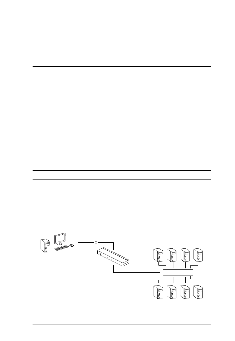
Overview
The KN1000 is a control unit that provides remote BIOS-level access to servers
or “over-IP” capability to KVM switches that do not have built in over-IP
functionality. It allows operators to monitor and access their computers from
remote locations using a standard Internet browser or Windows and Java based
application programs. In addition, the KN1000 offers out-of-band access,
including external modem support, and supports BIOS-level troubleshooting
without the need for constant on-site IT maintenance.
To help you manage and control your entire data center environment, a builtin single-port power switch allows remote power management of a server/
installation connected locally to the KN1000. You can also add a PON* (Power
Over the NET™) power management unit and remotely control the power
status of devices in your installation, including monitoring their current status,
as well as turning servers on, off, and rebooting them.
Note: Requires a separate purchase.
The KN1000 connects to the Internet, an Intranet, LAN, or WAN using
industry standard Cat 5e cable, then uses a custom KVM cable to connect to a
local KVM switch or server. Because the KN1000 uses TCP/IP for its
communications protocol, the server or KVM switch it is connected to can be
accessed from any computer on the Net – whether that computer is located
down the hall, down the street, or half-way around the world.
KVM Switch
(Continues on next page.)
1

KN1000 User Manual
Operators at remote locations connect to the KN1000 via its IP address. Once
a connection has been established and authorization granted, the remote
computer can exchange keyboard, video and mouse signals with the server (or
servers on a KVM switch installation), just as if they were physically present
and working on the equipment directly.
KN1000’s Virtual Media function allows you to perform diagnostic testing,
file transfer, and OS and application patches from a remote console. There is
no need to physically load a CD directly to the server to perform data-related
tasks – you can conveniently and efficiently troubleshoot and resolve problems
at the BIOS level from anywhere.
The Administrator and Client software included with the KN1000 make it easy
to install, maintain, and operate. System administrators can handle a multitude
of tasks with ease – from installing and running GUI applications, to BIOS
level troubleshooting, routine monitoring, concurrent maintenan ce, system
administration, rebooting and even pre-booting functions.
The Administrator Utility is available in a browser-based version as well as
Windows-based and Java application versions. The utility is used to configure
the system; limit access from remote computers; manage users; and maintain
the system with firmware and software module updates.
A Windows Client Viewer and a Java Applet Viewer are available for browser
access, while Windows Client AP and Java Client AP programs are provided
for non-browser GUI access. They allow IP connection and login from
anywhere on the net. Inclusion of a Java-based client ensures that the KN1000
is platform independent, and is able to work with practically all operating
systems. The KN1000 also provides serial console management over the
Internet, which can remotely control serial console devices such as a network
switch.
The client software allows access to, and control of, the connected servers.
Once an operator successfully connects and logs in, his screen displays what is
running on the remote unit attached to the KN1000 (a KVM OSD display, a
server's desktop, or a running program, for example) and he can control it from
his console just as if he were there.
The Log Server records all the events that take place on selected KN1000 units
for the administrator to analyze.
Your KN1000 investment is protected through the ability of its firmware to be
upgraded over the internet. You can stay current with the latest functionality
improvements by downloading firmware update files from our website as they
become available, and then using the utility to quickly and conveniently
perform the upgrade.
2

1. Introduction
Features and Benefits
The features and benefits provided by a KN1000 deployment are described in
the following table:
Features Benefits
Over-IP
Capability for
Legacy KVM
Switches or KVM
switches that do
not have built in
over-IP
functionality
Configuration and
Operation Ease
Remote Power
Control with
Wake on LAN
Superior Video With its enhanced fps throughput for crisp responsive video display,
Virtual Media USB 1.1 and 2.0 devices (Floppy drives, CDROMs, Flash drives,
Virtual Remote
Desktop
Protects your original KVM switch investment. No need to
purchase new KVM switches to achieve the benefits of over-IP
connectivity.
Compatible KVM Switches include the following: CS9134, CS9138,
CS88A, CS1308, CS1316, CS1754*, CS1758*, CS1708A,
CS1716A, ACS1208A, ACS1216A, KH2508A, KH2516A,
KH1508A, and KH1516A
*Some of the KN1000’s features may not be suppo rted, depending on the functionality of
the connected KVM switch. (For example, some switches do not support virtual media.)
*Some features found on the connected KVM switches may not be supported on the
KN1000. (For example, the CS1754’s audio.)
An easy-to-navigate graphical user interface makes for convenient,
intuitive configuration and operation. Web-based Windows and
Java implementations allow the remote equipment to be controlled
from industry-standard web browsers. Windows and Java AP client
software – using the same, convenient, GUI – are also included to
provide access where a browser environment is not desired.
1. A built-in single-port power switch allows remote power
management of a server/installation connected locally to the
KN1000.
2. In addition, you can also add a PON (Power Over the NET™)
power management unit and remotely control the power status of
devices on your installation, including monitoring their current
status, as well as turning servers On, Off and Rebooting them.
the KN1000 offers resolutions of up to 1600 x 1200 @ 60Hz;
vibrant 24-bit color depth for rich remote session display. The
remote desktop can appear full-screen, or in a window. In fullscreen mode the remote desktop display scales to the user’s
monitor display size.
etc.), folders, and image files on a user’s local system, appear and
act as if they were installed on the remote server, for ease and
convenience when performing software installation and system
updates across the entire Installation.
On-screen keyboard with multilanguage support
Exit Macros support
BIOS-level access
3

KN1000 User Manual
Features Benefits
Smart Card / CAC
Reader Support
Built in Single Port
Power Switch
Low Bandwidth
Optimization
Multi-Platform /
Multi-Protocol
Support
Manage Browser
Access Methods
Multi-Keyboard
Language
Support /
On-Screen
Keyboard
Multi-Users /
Multi-Logins
Message Board To alleviate the possibility of access conflicts that may result from
Advanced
Security
To meet advanced security requirements, the KN1000’s Virtual
Media function allows a Smart Card / CAC reader on a user’s local
system to be mapped to a remote server.
Allows remote power management of a server/installation
connected locally to the KN1000, including turning servers On, Off
and Rebooting
Bandwidth optimization via grayscaling and video quality settings
allow maximum data throughput in low bandwidth situations. PPP
modem dialup support ensures reliable connectivity for out-ofband, and low bandwidth situations.
Windows and Java client software ensures that the KN1000 and
the equipment that connects to it can be accessed from most of the
operating systems in use today (Windows, Linux, Unix, Sun, Mac).
The KN1000 also supports a broad range of communication
protocols, such as TCP/IP, HTTP, HTTPS, UDP, DHCP, SSL, ARP,
DNS, ICMP, CHAP, PPP, 10Base-T, 100Base-T
Use either HTTP or HTTPS; as well as disable the browser.
The KN1000 supports multiple keyboard language input – including
English, French, German, Italian, Spanish, Japanese, Korean, and
Traditional Chinese. There is no need to have a separate keyboard
for each language – you can input key data in any of these
languages with the KN1000's convenient on-screen keyboard.
The KN1000 supports up to 64 user accounts, and allows up to 32
concurrent user logins for single-bus access.
multiple user logins, and facilitate communication among the
logged-in users, a message board – similar to an Internet chat
program – allows users to communicate with each other, and
provides mechanisms for a user to take exclusive control of the
KVM functions.
Advanced security features include password protection –
whereby a valid username and password must be given before
the client software will run – and advanced encryption
technologies, such as secure 128-bit SSL.
Flexible encryption design allows users to choose any
combination of 56-bit DES, 168-bit 3DES 256-bit AES, 128-bit
RC4, or Random for independent KB/Mouse, video, and virtual
media data encryption.
IP/MAC Filter for enhanced security protection
Supports password protection
Private CA
4

1. Introduction
Features Benefits
External
Authentication
Support
Event Logging The KN1000 can record all the events that take place on it and
Console
Management
In addition to its own security protection, the KN1000 allows you to
set up log in authentication and authorization management from a
external sources such as RADIUS, LDAP, LDAPS, and MS Active
Directory.
write them to a searchable database. Administrators and selected
users can search for events containing specific words or strings
and retrieve them according to date and order of significance.
Serial console management – serial terminal access. Access the
KN1000 via a built-in serial viewer, or via third party software
(such as PuTTY) for Telnet and SSH sessions.
Out of Band Support – via dial up modem support. Access the
KN1000 through its RS-232 port using a dial-up connection.
Upgradeable
Firmware over
the Internet
Mouse DynaSync No need to re-sync your mouse – Mouse DynaSync provides
Auto-Ping Pings a device to determine its status, if the ping test fails after a
Supports multiple
interface
Full-Screen or
Sizable Remote
Desktop Window
DDNS Allows the mapping of a dynamic IP address assigned by a DHCP
On/Off
scheduling for
power outlet
Safe shutdown
support
End session Administrators can terminate running sessions
Magic Panel Special hideaway control panel with configurable function icons.
No need to add yet another cable to your installation – stay current
with the latest functionality improvements and updates, all over the
Internet.
automatic locked-in synching of the remote and local mouse
pointers – eliminating the need to constantly resync the two
movements. Your local console mouse movement becomes the
remote unit’s mouse movement.
set amount of time- it automatically takes an action assigned
Supports PS/2, USB, Sun Legacy (13W3)* and serial (RS-232)
connectivity
*Requires CV130A converter purchase
Get a full screen even if your monitor’s resolution is lower than the
remote computer’s resolution. In full-screen mode the remote
desktop display scales to the user’s monitor display size. Supports
up to 1600 x 1200 @ 60Hz; 24-bit color depth for remote sessions.
server to a host name.
Power management tasks can be scheduled on a daily, weekly,
monthly or user-specified time basis
IT administrators can control servers remotely and completely shut
down servers before powering them off.
5

KN1000 User Manual
System Requirements
Remote User Computers
Remote user computers (also referred to as client computers) are the ones the
users log into the switch with from remote locations over the internet (see
Terminology, page xii). The following equipment must be installed on th ese
computers:
For best results we recommend that the computers used to access the
switch have at least a P III 1 GHz processor, with their screen resolution
set to 1024 x 768.
Browsers must support 128 bit SSL encryption.
For best results, a network transfer speed of at least 128 kbps is
recommended.
For the Log Server, you must have the Microsoft Jet OLEDB 4.0 or higher
driver installed.
For Safe Shutdown:
The computer must be running Windows (Windows 2000 or higher), or
Linux.
The Safe Shutdown program (available by download from our
website), must be installed and running on the computer.
Servers
Servers are the computers connected to the switch via KVM Cables (see
Terminology, page xii). The following equipment must be installed on th ese
servers:
A VGA, SVGA or multisync port
For USB KVM Cable Connections: a Type A USB port and USB host
controller
For PS/2 KVM Cable Connections: 6-pin Mini-DIN keyboard and mouse
ports
6

1. Introduction
Cables
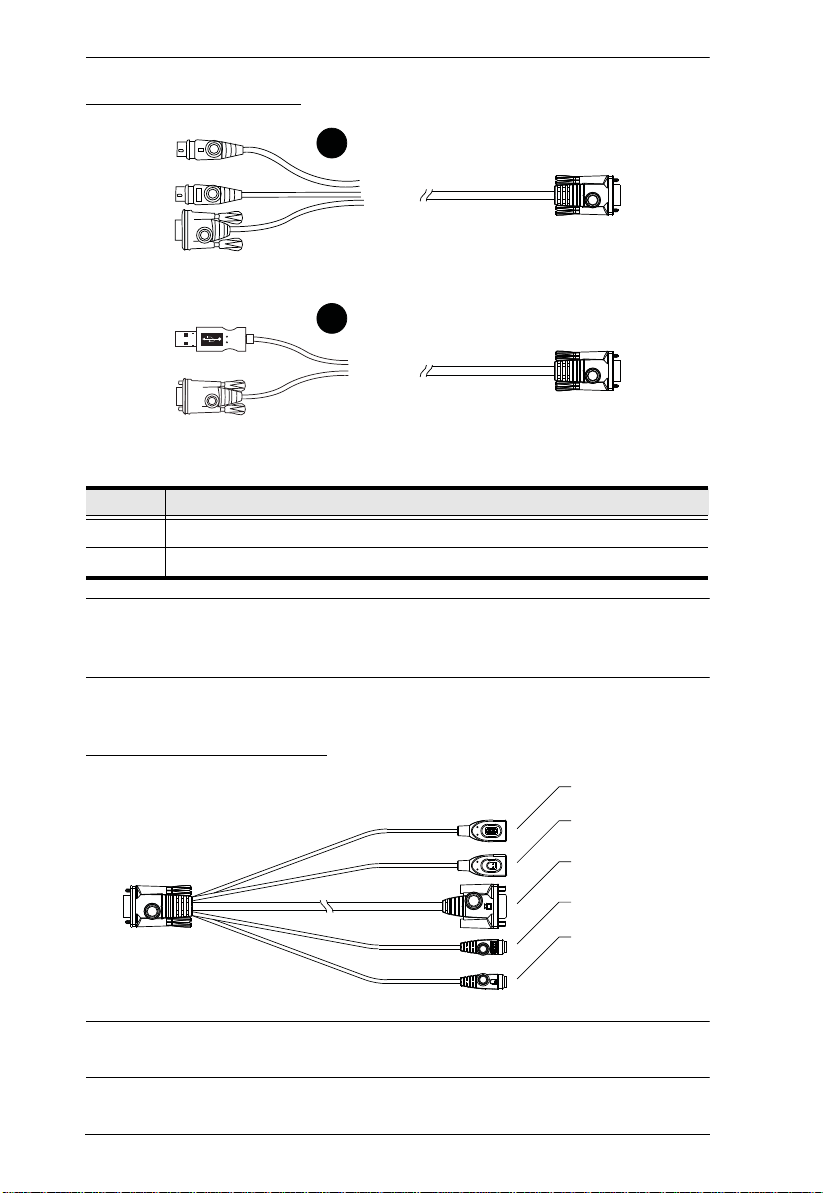
Two custom KVM cable sets (1 USB; 1 PS/2) to link the KN 1 000 to a
server or KVM switch are provided with this package.
Custom KVM cable sets are available in various lengths, as shown in the
table below:
Cable Type Length CS Part Number
PS/2 1.2 m 2L-5201P
1.8 m 2L-5202P
1.8 m 2L-5702P
3.0 m 2L-5203P
6.0 m 2L-5206P
USB 1.2 m 2L-5201U
1.8 m 2L-5202U
3.0 m 2L-5203U
5.0 m 2L-5205U
To purchase additional cable sets, contact your dealer.
One custom Console cable set to link the KN1000 to a local console is
provided with this package.
Note: This cable set has been designed to operate with either PS/2 or USB
consoles.
A USB 2.0 cable for use with the Virtual Media function (see Virtual
Media Port, page 11) is provided with this package.
Cat 5e or higher Ethernet cable (not provided with this package), should be
used to connect the KN1000 to the LAN, WAN, or Internet.
One power cable to connect the KN1000 to the server for power
management functionality is provided with this package.
7

KN1000 User Manual
Video
Only the following non-interlaced video signals are supported:
Resolution Refresh Rates
640 x 480 60, 72, 75, 85, 90, 100, 120
720 x 400 70
800 x 600 56, 60, 72, 75, 85, 90, 100, 120
1024 x 768 60, 70, 75, 85, 90, 100
1152 x 864 60, 70, 75, 85
1280 x 720 60
1280 x 1024 60, 70, 75, 85
1600 x 1200 60
Operating Systems
Supported operating systems for remote user computers that log into the
KN1000 include Windows 2000 and higher, and other systems capable of
running Sun's Java Runtime Environment (JRE) 6, Update 3, or higher
(Linux, Mac, Sun, etc.).
Supported operating systems for servers that connect to the KN1000 are
shown in the table, below:
OS Version
Windows 2000 and higher
Linux RedHat 7.1 and higher
Fedora Core 5 and higher
SuSE 9.0 and higher
Mandriva (Mandrake) 9.0 and higher
UNIX AIX 4.3 and higher
FreeBSD 3.51 and higher
Sun Solaris 8 and higher
Novell Netware 5.0 and higher
Mac OS 9 and higher
DOS 6.2 and higher
8

1. Introduction
Browsers
Supported browsers for users that log into the KN1000 include the following:
Browser Version
Internet Explorer 6 and higher
Chrome 8.0 and higher
Firefox Windows 3.5 and higher
Linux 3.0 and higher
Safari Windows 4.0 and higher
Mac 3.1 and higher
Opera 10,0 and higher
Mozilla Windows 1.7 and higher
Sun 1.7 and higher
Netscape 9.0 and higher
* See Mac Systems, page 170, for further information regarding Safari.
9

KN1000 User Manual
12345
6
Components
Front View
No. Component Description
1 LAN Port The Cat 5e cable that connects the KN1000 to the LAN, WAN,
2Firmware
Upgrade/Reset
Switch
3 10/100 Mbps
LED
4 Link LED Flashes GREEN to indicate that a Client program is accessing
5 Power LED Lights ORANGE when the KN1000 is powered up and ready
6 Power Outlet
LED
or Internet plugs in here.
1. Pressing and releasing this switch performs a KN1000
system reset. (See Erratic operation, page 166.)
2. Pressing and holding this switch for more than three
seconds returns the KN1000 to its factory default
configuration settings.
3. Pressing and holding this switch while powering on the
switch returns the KN1000 to its factory default firmware
level. This operation should only be performed in the event
of a firmware upgrade failure that results in the device
becoming inoperable.
Note: This switch is recessed and must be pushed with a thin
object - such as the end of a paper clip, or a ballpoint pen.
The LED lights ORANGE to indicate 10 Mbps data
transmission speed. It lights GREEN to indicate 100 Mbps
data transmission speed.
the device.
to operate.
Lights ORANGE when the server attached to the KN1000’s
power outlet is powered on
10

1. Introduction
Rear View
12 3 4 5 67 8 9 10
No. Component Description
1 Circuit Breaker As a safety measure, if there is an overcurrent
situation, the circuit breaker will trip. Press this button
to recover normal operation.
2 Grounding Terminal The wire used to ground the unit connects here.
3 Power Inlet The power cord that connects the KN1000 to an AC
power source for power management functionality
plugs in here.
4 Power Outlet The power cord provided with the KN1000 package
5 Power Ja ck The power adapter cable plugs in here.
6 Virtual Media Port The cable that connects the KN1000 to a USB port on
7 PC/KVM Port The KVM cable provided with this package that links
8 Console Port The cable for the local console (keyboard, monitor,
9 PON Port This port is made available for use with a Power over
10 RS-232 Port This serial port is provided for:
that connects to the server for power management
plugs in here. See Managing Power, page 25.
your server or KVM switch plugs in here. See Virtual
Media, page 94, for virtual media details.
the KN1000 to your server / KVM switch plugs in here.
and mouse) plugs in here. The console can use either
a PS/2 or USB keyboard and mouse. Each connector
is color coded and marked with an appropriate icon.
the NET™ remote power management module. Refer
to the User Manual that came with the PON device for
operation details.
1. Serial console management (see Console
Management, page 59 for details); or
2. Out-of-band modem operation (see OOBC,
page 62 for details).
11
KN1000 User Manual
2
1
USB Keyboard
USB Mouse
Video
PS/2 Keyboard
PS/2 Mouse
Custom KVM Cables
No. Description
1 For use with PS/2 configuration servers or KVM switches.
2 For use with USB configuration servers or KVM switches.
Note: The advantage of using a USB cable is that it allows automatic locked-
in mouse synchronization. See Mouse DynaSync Mode, page 102 , for
details.
Custom Console Cable
Note: You can use any combination of keyboard and mouse connections. For
example, you can use a PS/2 keyboard with a USB mouse.
12
Chapter 2
1. Important safety information regarding the placement of this device is
provided on page 149. Please review it before proceeding.
2. Make sure that the power to any device that you connect to the
installation has been turned off. You must unplug the power cords of
any computers that have the Keyboard Power On function.
3. Any installation that does not follow the instructions in this guide may
be hazardous.
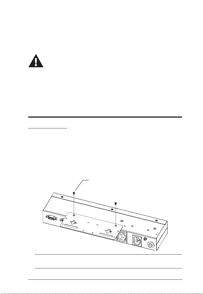
Phillips hex head
M3 x 8
Hardware Setup
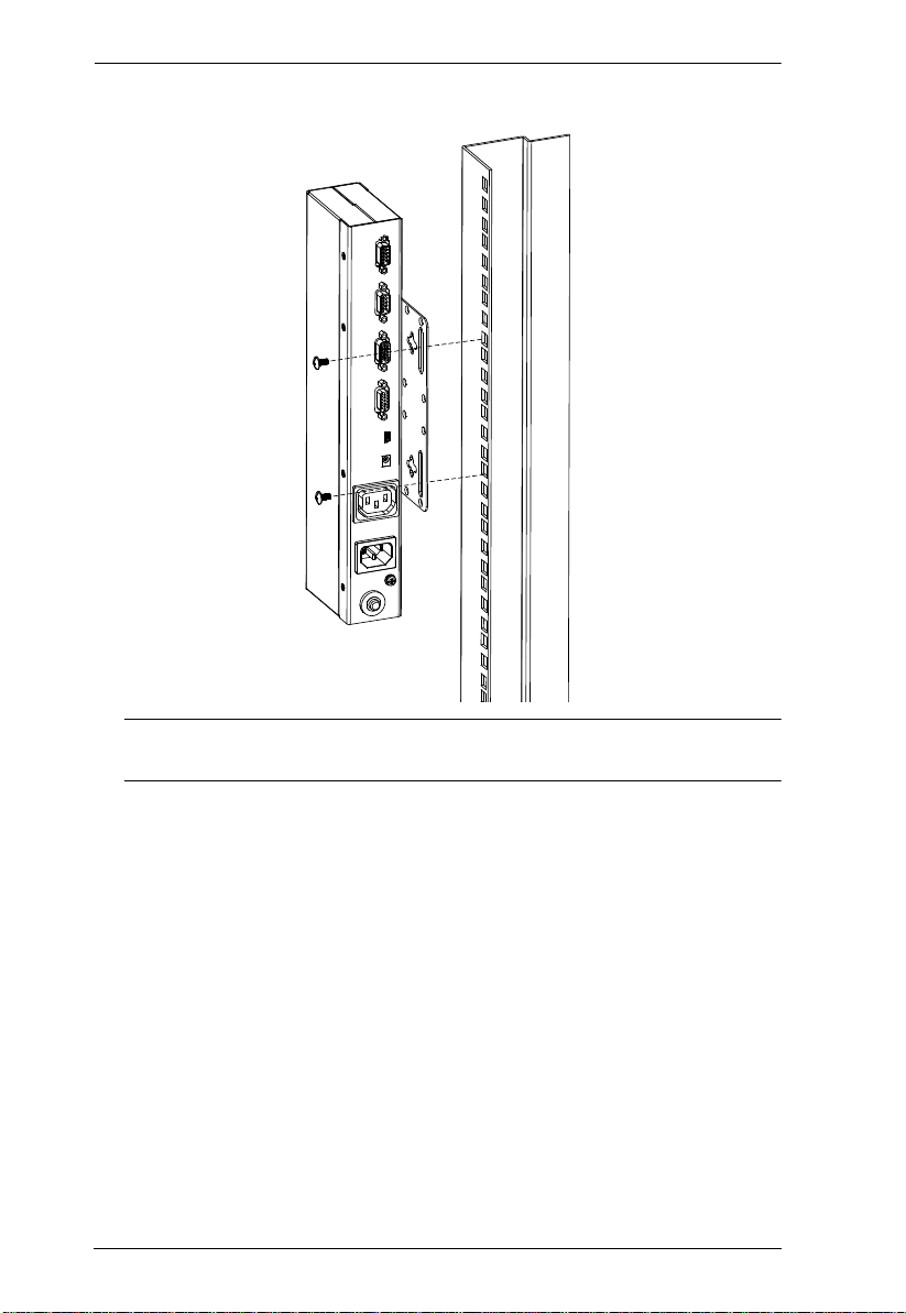
Mounting
Rack Mounting
For convenience and flexibility, the KN1000 can be mounted on a system rack.
To rack mount the unit do the following:
1. Remove the two original screws from the top/bottom of the unit (near the
rear of the unit).
2. Using the screws provided with the rack mount kit, screw the mounting
bracket into the KN1000 – as shown in the diagram below:
Note: The illustrations show the mounting bracket attached to the bottom
of the unit; it can also be attached to the top.
13
KN1000 User Manual
3. Screw the bracket into any convenient location on th e rack.
Note: Rack screws are not provided. Use screws that are appropriate for
your rack.
14
2. Hardware Setup
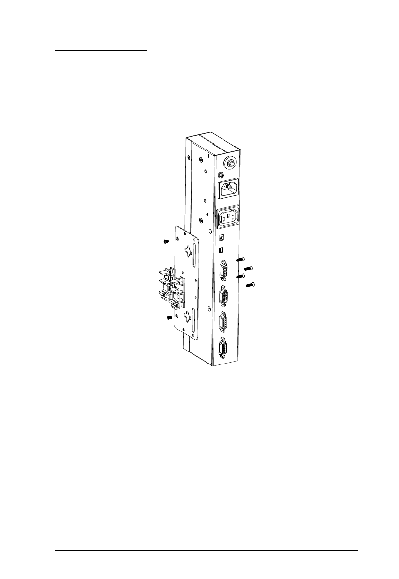
DIN Rail Mounting
To mount the KN1000 on a DIN rail:
1. Screw the mounting bracket to the back of the KN1000 as described in
steps 1 and 2 of the wall mounting procedure.
2. Use the larger screws supplied with the Rack Mount Kit to screw the DIN
rail brackets to the mounting bracket – as shown in the diagram, below:
3. Hang the unit on the DIN rail.
15

KN1000 User Manual
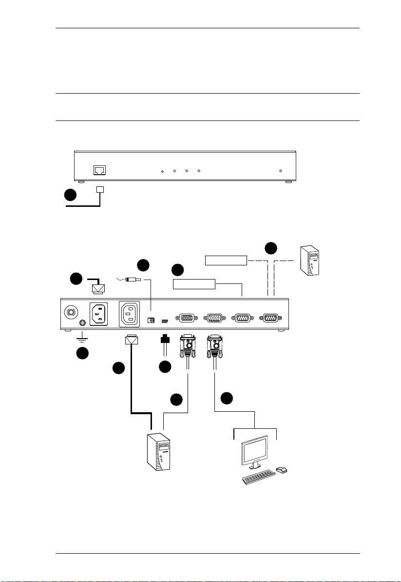
Installation
To install the KN1000, refer to the installation diagrams on the following pages
(the numbers correspond to the numbers of the steps), and do the following:
1. Ground the unit using a grounding wire.
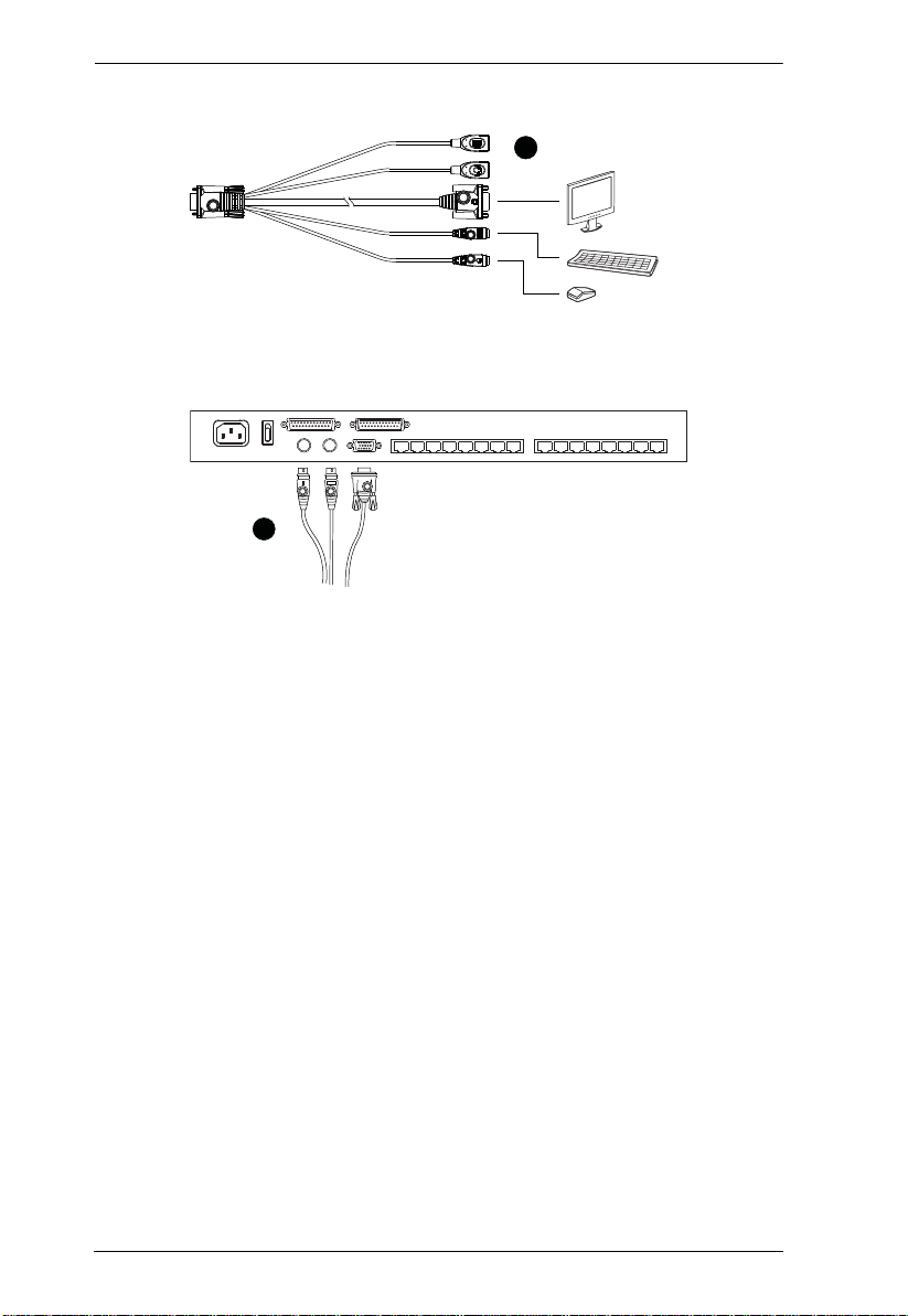
2. Use the Console cable provided with this package to connect the
KN1000’s Console port, to the local console keyboard, monitor and
mouse.
Note: 1. The Console cable comes with connectors for both PS/2 and USB
mice and keyboards – use the ones appropriate for your
installation.
2. You can use any combination of keyboard and mouse
connections. For example, you can use a PS/2 keyboard with a
USB mouse.
3. Use the KVM cable provided with this package to connect the KN1000’s
PC/KVM port, to the keyboard, video and mouse ports of the server or
KVM switch that you are installing.
Note: The KN1000’s virtual media features may not be supported,
depending on the functionality of the cascaded KVM switch (see
Supported KVM Switches, page 173).
4. (Optional) If you want to use the virtual medi a function (see Virtual
Media, page 94), use the USB 2.0 Virtual Media Cable provided with this
package to connect a USB port on the server to the KN1000's Virtual
Media port.
5. (Optional) If you want to connect a PON device for remote power
management, plug its cable into the PON port.
6. (Optional) If you want to connect a serial console device or modem, plug
its cable into the RS-232 port.
7. Plug the LAN or WAN cable into the KN1000's LAN port.
8. Use the outlet power cord provided with the KN1000 package to connect
the KN1000’s Power Outlet to the attached server for power management.
9. Use the power cord from the server to connect the KN1000’s Power Inlet
to an AC power source.
16
2. Hardware Setup
10.Plug the power adapter cable into the KN1000's power jack, then plug the
power adapter into an AC power source.
This completes the hardware installation, and you are ready to start up.
Note: When starting up, be sure to first power on the KN1000, then power on
the server or KVM switch.
7
6
10
9
5
PN0108
Modem
Serial Console Device
(Router, Switch, Sunre V100,....)
1
8
4
3
2
17
KN1000 User Manual
2
1
18

Chapter 3
Browser Login
The KN1000 can be accessed either from an internet type browser, via
Windows and Java application (AP) program, or by PPP modem dial-in. The
next several chapters describe browser-based operations; AP access is
discussed in Chapter 9; PPP modem login is discussed on page 159.
Note: Windows Vista/7 users who want to use the KN1000’s Virtual Media
feature must run the internet browser as an Administrator. See Virtual
Media, page 94, for further details.
Logging In
To operate the KN1000 from an Internet browser, begin by logging in:
1. Open your browser and specify the IP address of the KN1000 you want to
access in the browser's URL location bar.
Note: 1. For security purposes, a login string may have been set by the
administrator. If so, you must include a forward slash and the
login string along with the IP address when you log in. For
example:
192.168.0.100/KN1000
If you don't know the IP address and login string, ask your
Administrator.
2. If you are the administrator, and are logging in for the first time,
the various ways to determine the KN1000's IP address are
described in the Appendix on page 153.
(Continues on next page.)
19

KN1000 User Manual
(Continued from previous page.)
2. A Security Alert dialog box appears.
Accept the certificate – it can be trusted. (See Trusted Certificates,
page 161, for details.) If a second certificate appears, accept it as well.
The KN1000 login page appears:
20

3. Browser Login
3. Provide a valid Username and Password (set by the KN1000
administrator), then click Login to continue.
Note: 1. If you are the administrator, and are logging in for the first time,
use the default Username: administrator; and the default
Password: password. For security purposes, we strongly
recommend you remove these and give yourself a unique
Username and Password (see User Management, page 57).
2. If you supplied an invalid login, the authentication routine will
return this message: Invalid Username or Password. Please try
again. If you see this message, log in again being careful with the
Username and Password.
After you have successfully logged in, the KN1000 Main Screen appears:
21

KN1000 User Manual
Main Webpage Elements
The Main page consists of user access icons arranged vertically down the left
side; administrative function icons arranged across the top; a Remote Console
Preview window with an icon to launch the Java or WinClient Viewer
displayed in the center; and an Exit Macro list box just below the Remote
Console Preview
Note: If a user doesn’t have permission to perform a particular activity, the
icon for that activity doesn’t appear. See User Management, page 57,
for permission details.
Utility Icons
The icons arranged down the left side perform the following functions:
Icon Purpose
Remote Console: Clicking this icon closes whatever is displayed on
the Main Screen, and brings back the Remote Console Preview.
(See Remote Console Preview, page23.)
Power Management: If you have the proper permission (see User
Management, page 57), clicking this icon will bring up the KN1000’s
power control interface, allowing you to reset power over the network and
use the Wake on LAN feature. See Managing Power, page25.
Log: All the events that take place on the KN1000 are recorded in a log
file. If you have the proper permission (see User Management, page 57),
clicking this icon displays the contents of the log file. The Log File is
discussed in Chapter 7.
User Preferences: Click this icon to set up your own, individual,
browsing environment. The switch stores a separate configuration record
for each user profile, and sets up the browser configuration according to
the Username that you key into the Login dialog box. (See , page 30.)
Logout: Click this icon to log out and end your KN1000 session.
It is important to log out when you end your session. Otherwise, you must
wait until the timeout setting has expired before the KN1000 can be
accessed again. (See Timeout, page 66.)
Administrative Function Icons
The icons arranged horizontally across the top of the page are linked to the
administration utilities, which are used to configure the KN1000. The
administrative functions are discussed in Chapter 4.
22

3. Browser Login
Remote Console Preview
The main portion of the panel shows a snapshot of the server’s display.
Clicking Refresh updates the snapshot of the remote display.
The links that appear below the Refresh button depend on the browser you are
using, and your User Preferences Viewer choice (see page 33):
If you are logging in with a browser other than Windows Internet Explorer,
a Java Applet Viewer icon (a steaming cup of coffee), and the link words
“Open Viewer” display.
If you are logging in with IE as your browser, and you chose Auto Detect
as your Viewer choice (the default), The WinClient icon and the link
words “Open Viewer” display.
If you are logging in with IE as your browser, and you chose Java as your
Viewer choice a Java Applet Viewer icon (a steaming cup of coffee), and
the link words “Open Viewer” display.
If you are logging in with IE as your browser, and you chose User Select
as your Viewer choice, both the Java Applet Viewer and WinClient Viewer
icons appear.
Click the appropriate link to have the viewer open the remote server’s display
on your desktop. Java Applet Viewer operation is discussed in Chapter 6;
WinClient Viewer operation is discussed in Chapter 5.
Note: If you selected Auto Detect or Java, you can also open the remote
server’s display by clicking on the snapshot window directly.
23

KN1000 User Manual
Exit Macro
The Exit Macro panel contains a dropdown list box of user created System
macros:
You can select a macro from the list that will execute when exiting the remote
server. See System Macros, page 86, for details on creating exit macros.
Telnet/SSH Viewer
If Serial Console Management has been enabled (see Serial Console, page 59),
a Telnet/SSH Viewer panel displays directly below the Exit Macro panel:
These viewers allow users to open a Telnet or SSH session to the KN1000 from
the browser. Depending on the user’s permissions (see Permissions, page 58),
the Telnet Viewer link or SSH Viewer link, or both links are shown.
Click the appropriate link to have the viewer open the session.
24

3. Browser Login
Managing Power
To help you manage and control your entire data center environment, a builtin single-port power switch allows remote power management of a server/
installation connected locally to the KN1000. You can also add a PON (Power
Over the NET™) power management unit and remotely control the power
status of devices in your installation, as well as turning servers on and off.
If you have the proper permission (see User Management, page 53), clicking
this icon will bring up the KN1000’s power control interface, allowing you to
reset power over the network, use the Wake on LAN feature, schedule routines,
use the Auto Ping function. These are all detailed in the sections that follow:
25

KN1000 User Manual
Power Management
This section lets you set up the power management for the KN1000’s power
switch.
The meanings of the field headings are given in the following table:
Click the Outlet icon to power operations on and off. A green outlet
icon indicates that the power is currently On.
Confirmation
Required
Power On
Delay
Power Off
Delay
If this option is enabled (there is a check in the checkbox), a dialog box
comes up asking you to confirm a power operation before it is
performed. If it is disabled (there is no check in the checkbox), the
operation is performed without confirmation.
Sets the amount of time the KN1000 waits after the Power Button is
clicked before it turns on the power to the outlet.
Note: The default delay time is 0 seconds; the maximum is 999
seconds.
Sets the amount of time the KN1000 waits after the Power Button is
clicked before it turns off the power to the outlet.
For the System after AC Back option (see below), after the delay time
expires, the KN1000 waits another fifteen seconds, then shuts the
computer down.
The default delay time is 15 seconds. The maximum delay time is 999
seconds.
26

3. Browser Login
Shutdown
Method
MAC In order to use either of the Safe Shutdown methods the MAC address
There are three choices for the Shutdown method. Drop down the list
to select a choice. The meaning of each choice is described, below:
Wake on LAN: This is a Safe Shutdown and Restart option. If this is
selected, when an Outlet is turned Off, the KN1000 first sends a
message to the computer telling it to prepare for a shutdown; it then
waits for the amount time set in the Power Off Delay field to give the
OS time to close down before the computer is powered down to
standby mode.
Likewise, when the Outlet is turned On, the KN1000 waits for the
amount time set in the Power On Delay field, then sends an Ethernet
message to the computer connected to the Outlet telling the
computer to turn itself On.
Note: For Safe Shutdown and Restart, the computer must be running
Windows (98 or higher), or Linux, and the Safe Shutdown program
(available by download from our website), must be installed and
running on the computer. See System Requirements, page 6, for
details.
System after AC Back: This is a Safe Shutdown and Restart option. If
this is selected, when an Outlet is turned Off, the KN1000 first sends
a message to the computer telling it to prepare for a shutdown; it then
waits for the amount time set in the Power Off Delay field to give the
OS time to close down before the computer is powered down.
When the Outlet is turned On, the KN1000 waits for the amount time
set in the Power On Delay field, then sends power to the server.
When the server receives the power, it turns itself on.
Note: For Safe Shutdown and Reboot, the computer must be running
Windows (98 or higher), or Linux, and the Safe Shutdown program
(available by download from our website), must be installed and
running on the computer. See System Requirements, page 6, for
details.
Kill the Power: If this option is selected, the KN1000 waits for the
amount time set in the Power Off Delay field, and then turns the
Outlet's power Off. Turning the power off performs a cold (non-safe)
shutdown.
of the computer connected to the outlet must be filled in here.
27

KN1000 User Manual
Schedule
Clicking the Add button in the Schedule section brings up a page that lets you
set up a scheduled power On/Off configuration for the selected outlet:
Note: Since the KN1000 has no RTC (real time clock) circuit, the unit will get
time from the NTP server or from the client PC (sync time from client
PC after a system reset or losing power).
The meanings of the field headings are given in the table, below:
Heading Meaning
Routine Type Drop down the list to select whether the scheduled power
Week Day This field only becomes active if you choose Weekly as the
Date This field only becomes active if you choose Monthly as the
Start Date If you want to limit the power management routine to a
End Date If you want to limit the power management routine to a
28
configuration should take place just Once, or on a Daily,
Weekly, or Monthly basis.
routine type. If you choose Weekly , drop down the list to choose
which day of the week you want the power management routine
to take place on.
routine type. If you choose Monthly, drop down the list to
choose which day of the month you want the power
management routine to take place on.
particular time period, either click the calendar icon to select the
date that the routine will start at, or key in a start date using the
YYYY-MM-DD format
particular time period, either click the calendar icon to select the
date that the routine will end at, or key in an end date using the
YYYY-MM-DD format

3. Browser Login
Heading Meaning
Shutdown Time Key in the time of day you want the shutdown to take place
Restart Time Key in the time of day you want the restart to take place using
Every For added flexibility, you can use this field to refine the Daily,
using the HH:MM format.
If you want to temporarily suspend this function without deleting
the entry, click to put a check in the Disable checkbox at the
right of this field. You can reinstate the function by unchecking
the checkbox.
the HH:MM format.
If you want to temporarily suspend this function without deleting
the entry, click to put a check in the Disable checkbox at the
right of this field. You can reinstate the function by unchecking
the checkbox.
Weekly, and Monthly routines. For example, if you chose Daily
as your routine type, you could have the routine take place
every 3 days (instead of every day), by keying a 3 in this field.
After you have made your schedule settings, click Add. The schedule is
summarized in the list at the bottom of the panel. To remove the outlet’s
schedule, select it in the list and click Delete.
29

KN1000 User Manual
Auto Ping
The section allows you to use an ICMP ping command to check if the attached
device is functioning properly. This function is detailed in the following table:
Enable Put a check in the checkbox to enable this function.
Ping
Address
Interval This field sets how often the specified device is pinged, in second
Fail Count This field sets how many times the device is allowed to fail to respond to
Action This field sets what action is taken if the device fails to respond to a
Enter the IP address of the device to be be pinged in this field.
intervals. Enter a value between 1 and 255.
the ping before an action is taken (see below). Enter a value between 1
and 99.
specified number of pings. Select one of the following actions from the
drop-down menu:
Send email: This sends an email using the SMTP server setting. For
this function to work, you must also enable reports from the SMTP
server. See SMTP Settings, page 41 for details.
Outlet Power Off/On: This resets the power at the KN1000’s power
outlet.
Note: This action must be confirmed before saving.
No action: Select this option to do nothing if the specified device fails to
respond.
Note: If Auto Ping fails, after power on, the KN1000 waits five minutes before
performing the next ping operation.
30

3. Browser Login
PON Port Setting
This section allows you to configure the KN1000’s PON port for connecting a
PN0108 (8-port Power Over the NET™) or a 2-wire RS-232 interface.
PON Device
Enable this radio button if you want to connect a PN0108 (8-port Power Over
the NET™) to the KN1000’s PON port. If a Power over the Net™ module is
connected to your installation, click Download PON Client to download the
KN1000‘s power management software for the attached PON device.
Enable 2-Wire RS232
Enable this radio button to use the PON port for a serial console. When this
option is selected, a menu window appears for the serial communication
parameters, as below:
Note: These settings will be the same as those in the KN1000’s serial console
section. See the Serial Console section under Console Management,
page 59, for further details.
(Continues on next page.)
31

KN1000 User Manual
(Continued from previous page.)
If both RS-232 functions are enabled (PON for 2-wire RS-232 and RS-232 for
a serial console), when the Telnet/SSH connection is opened, a menu appears
for you to select which serial console is the primary, where Port 1 is the serial
console and Port 2 is the 2-wire RS-232, as shown below:
32

3. Browser Login
User Preferences
The User Preferences page allows the user to set three parameters: Viewer,
Language, and Password:
The page settings are explained in the following table:
Setting Function
Viewer You can choose which viewer is used when accessing a server:
Auto Detect will select the appropriate viewer based on the web
browser used; WinClient for Windows Internet Explorer; Java Client for
other web browsers (Firefox, etc.).
Java will open the Java based viewer regardless of the web bro wser
being used.
User Select lets IE users bypass the Auto Detect choice and choose
for themselves whether to use the WinClient or Java Applet Viewer.
After making your choice, click Apply.
Language Selects the language that the interface displays in. Drop down the list to
Change
Password
make your selection.
Selecting Auto causes the KN1000 to display the pages in the same
language that the browser is set to.
Note: If your browser is set to a non-supported language, the KN1000
looks to what your server’s operating system is set to. If the operating
system is set to a supported language it will use that language to display
its pages. If the operating system is set to a non-supported language, the
KN1000 defaults to English.
After making your choice, click Apply.
To change your password, key the new password into the New Password
input box; key the exact same characters into the Confirm New Password
input box; then click Change Password to set the new password.
33

KN1000 User Manual
This Page Intentionally Left Blank
34

Chapter 4
Administration
Introduction
The administration utilities, represented by the icons located across the top of
the KN1000 web page, are used to configure the KN1000’s operating
environment.
This chapter discusses each of them in turn.
Note: 1. As you make your configuration changes in each dialog box, click
Apply to save them.
2. Some configuration changes only take effect after a KN1000 reset.
For those changes, a check is automatically put in the Reset on Exit
box (see Customization, page 66). To have the changes take effect,
log out and then log back in again.
3. If you don't have Configuration privileges (see User Management,
page 57), the Administration configuration dialogs are not avail a ble.
35

KN1000 User Manual
Device Information
The Device Information page is the first of the Administration pages, and
provides information about the KN1000's status.
An explanation of each of the fields is given in the table below:
Field Explanation
Device Name: To make it easier to manage installations that have more than one
MAC Address: The KN1000's MAC Address displays here.
Firmware Version: Indicates the KN1000's current firmware version level. New
IPV4 Address Displays the KN1000’s Internet Protocol Version 4 (32 bit) address
DNS The IP address of the Domain Name Server.
IPV6 Address Displays the KN1000’s Internet Protocol Version 6 (128 bit) address
KN1000, each one can be given a name. To assign a name for the
KN1000, key in one of your choosing here (16 characters max.),
then click Apply.
versions of the KN1000's firmware can be downloaded from our
website as they become available (see Firmware Upgrade,
page 70). You can reference this number to see if there are newer
versions available on the website.
(in the legacy format).
(in the new format). See IPv6, page 155 for details.
36

4. Administration
Network
The Network dialog is used to specify the KN1000's network environment.
Service Ports
If a firewall is being used, the Administrator can specify the port numbers that
the firewall will allow (and set the firewall accordingly). If a port other than the
default is set, users must specify the port number as part of the IP address when
they log in. If not, an invalid port number (or no port number) is specified, the
KN1000 will not be found.
(Continues on next page.)
37

KN1000 User Manual
(Continued from previous page.)
An explanation of the fields is given in the table below:
Field Explanation
HTTP The port number for a browser login. The default is 80.
HTTPS The port number for a secure browser login. The default is 443.
Telnet Port The port for Telnet access. The default is 23.
Program This is the port number for connecting to the KN1000 from the
Virtual Media This is the port number used for data transfer using the KN1000’s
SSH Port The port for SSH access. The default is 22.
Windows Client and Java Applet Viewers, and from the Windows
and Java AP programs. The default is 9000.
virtual media feature. Valid entries are from 1–65535. The default is
9003.
Note: 1. Valid entries for all of the Service Ports are from 1–65535.
2. The service ports cannot have the same value. You must set a
different value for each one.
3. If there is no firewall (on an Intranet, for example), it doesn’t matter
what these numbers are set to, since they have no effect.
IP Address
The KN1000 can either have its IP address assigned dynamically at bootup
(DHCP), or it can be given a fixed IP address.
For dynamic IP address assignment, select the Obtain an IP address
automatically, radio button. (This is the default setting.)
To specify a fixed IP address, select the Set IP address manually, radio
button and fill in the IP address.
Note: 1. If you choose Obtain IP address automatically, when the switch starts
up it waits to get its IP address from the DHCP server. If it hasn’t
obtained the address after one minute, it automatically reverts to its
factory default IP address (192.168.0.60.)
2. If the KN1000 is on a network that uses DHCP to assign network
addresses, and you need to ascertain its IP address, see IP Address
Determination, page 153, for information.
38

4. Administration
DNS Server
The KN1000 can either have its DNS server address assigned automatically, or
a fixed address can be specified.
For automatic DNS Server address assignment, select the Obtain DNS
server address automatically, radio button.
To specify a fixed address, select the Use the following DNS server
address, radio button and fill in the required information.
Note: Specifying at the alternate DNS Server address is optional.
Network Transfer Rate
This setting allows you to tailor the size of the data transfer stream to match
network traffic conditions by setting the rate at which the KN1000 transfers
data to remote computers. The range is from 4–99999 Kilobytes per second
(KBps).
Finishing Up
After making any network changes, be sure Reset on exit on the Customization
page (see Customization, page 66) has been enabled (there is a check in the
checkbox), before logging out. This allows network changes to take effect
without having to power the KN1000 off and on.
39

KN1000 User Manual
ANMS
The Advanced Network Management Settings page allows you to set up login
authentication and authorization management from external sources. It is
divided into several sections, each of which is described in the sections that
follow.
IP Installer
The IP Installer is an external Windows-based utility for assigning IP addresses
to the KN1000.
Click one of the radio buttons to select Enable, View Only, or Disable for the
IP Installer utility. See page 153for IP Installer details.
Note: 1. If you select View Only, you will be able to see the KN1000 in the IP
Installer’s Device List, but you will not be able to change the IP
address.
2. For security, we strongly recommend th at you set thi s to View Only
or Disable after using it.
40
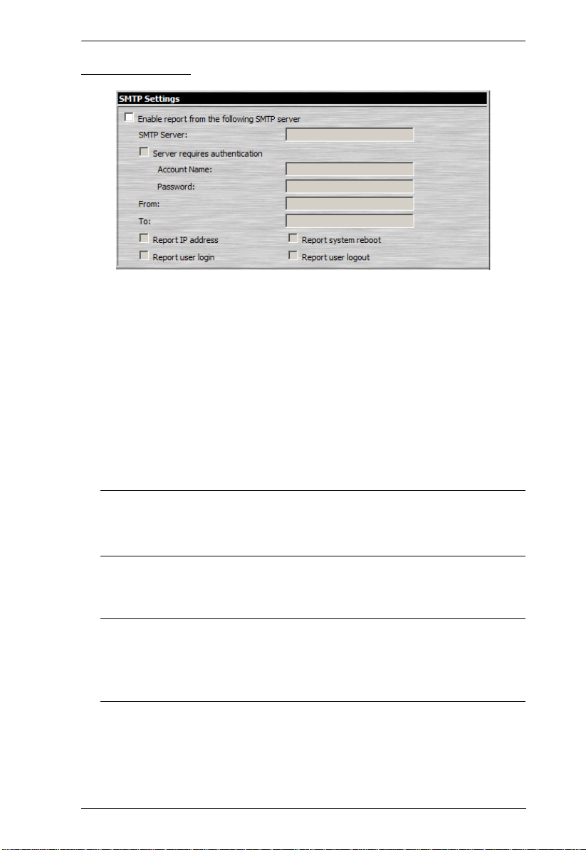
4. Administration
SMTP Settings
To have the KN1000 email reports from the SMTP server to you, do the
following:
1. Enable the Enable report from the following SMTP server, and key in the
IP address of your SMTP server.
2. If your server requires authentication, put a check in the Server requires
authentication checkbox, and key in the appropriate account information
in the Account Name and Password fields.
3. Key in the email address of where the report is being sent from in the From
field.
Note: 1. Only one email address is allowed in the From field, and it cannot
exceed 64 Bytes.
2. 1 Byte = 1 English alphanumeric character.
4. Key in the email address (addresses) of where you want the SMTP reports
sent to in the To field.
Note: 1. If you are sending the report to more than one email address,
separate the addresses with a semicolon. The total cannot exceed
256 Bytes.
2. 1 Byte = 1 English alphanumeric character.
5. Select the report options you would like sent. Choices incl ude: Report IP
address, Report system reboot, Report user login and Report user logout.
41

KN1000 User Manual
Log Server
Important transactions that occur on the KN1000, such as logins and internal
status messages, are kept in an automatically generated log file
Specify the MAC address of the computer that the Log Server runs on in
the MAC address field.
Specify the port used by the computer that the Log Server runs on to listen
for log details in the Port field. The valid port range is 1–65535. The
default port number is 9001.
Note: The port number must different than the one used for the Program
port (see Program, page 38).
See Chapter 8, The Log Server, for details on setting up the log server. The Log
File is discussed on page 121.
SNMP Server
To be notified of SNMP trap events, do the following:
1. Check Enable SNMP Agent.
2. Key in the IP address and the port number of the computer to be notified of
SNMP trap events. The valid port range is 1-65535.
Note: The following SNMP trap events are sent: System Power On, Login
Failure, and System Reset.
42

4. Administration
Syslog Server
To record all the events that take place on the KN1000 and write them to a
Syslog server, do the following:
1. Check Enable.
2. Key in the IP address and the port number of the Syslog server. The valid
port range is 1-65535.
DDNS
DDNS allows the mapping of a dynamic IP address assigned by a DHCP server
to a hostname. To provide DDNS capability for the KN1000, do the following:
1. Check Enable.
2. Enter the hostname that you registered with your DDNS service provider.
3. Drop down the list to select the DDNS service you are registered with.
4. Key in the Username and Password that authenticates you with your
DDNS service.
5. If the KN1000’s IP address changes, it must update the DDNS server so
that the new address is properly associated with its hostname. If it fails to
update the DDNS server, it must try again at a later time. Key in the
amount of time (in hours) to wait before trying to update the DHCP server
again.
43

KN1000 User Manual
Disable Local Authentication
Selecting this option will disable login authentication locally on the KN1000.
The switch can only be accessed using LDAP, LDAPS, MS Active Directory,
RADIUS or CC Management authentication.
RADIUS Settings
To allow authentication and authorization for the KN1000 through a RADIUS
server, do the following:
1. Check Enable.
2. Fill in the IP addresses and port numbers for the Preferred and Alternate
RADIUS servers.
3. In the Timeout field, set the time in seconds that the KN1000 waits for a
RADIUS server reply before it times out.
4. In the Retries field, set the number of allowed RADIUS retries.
5. In the Shared Secret field, key in the character string that you want to use
for authentication between the KN1000 and the RADIUS Server.
44

4. Administration
6. On the RADIUS server, set the access rights for each user according to the
information in the table, below:
Character Meaning
c Grants the user administrator privileges, allowing the user to configure
the system.
w Allows the user to access the system via the Windows Client program.
j Allows the user to access the system via the Java applet.
p Allows the user to Power On/Off, Reset devices via an attached
PN0108.
l Allows the user to access log information via the user's browser.
v Limits the user's access to only viewing the video display.
s Allows the user to use the Virtual Media function in Read Only mode.
m Allows the user to use the Virtual Media function in Read/Write mode.
t Allows the user to access the system via a Telnet session.
h Allows the user to access the system via an SSH session.
a Allows the user to access the system via a Telnet or SSH session
su/user Where user represents the Username of a KN1000 user whose
permissions reflect the permissions you want the RADIUS authorized
user to have.
Note: 1. The characters are not case sensitive. Capitals or lower case work
equally well.
2. Characters are comma delimited.
RADIUS Examples
RADIUS Server access rights examples are given in the table, below:
String Meaning
c,w,p User has administrator privileges; user can access the system via the
Windows Client; user can access the attached PN0108
w,j,l User can access the system via the Windows Client; user can access the
system via the Java Applet; user can access log information via the user's
browser.
45

KN1000 User Manual
CC Management Settings
To allow authorization for the KN1000 through a CC (Control Center) server,
check Enable and fill in the CC Server’s IP address and the port that it listens
on in the appropriate fields.
LDAP Settings
The KN1000 allows log in authentication and authorization through external
programs. To allow authentication and authorization via LDAP or LDAPS, the
Active Directory’s LDAP Schema must be extended so that an extended
attribute name for the KN1000 – KN1000-accessRight – is added as an
optional attribute to the person class.
Note: Authentication refers to determining the authenticity of the person
logging in; authorization refers to assigning permission to use the
device’s various functions.
In order to configure the LDAP server, you will have to complete the following
procedures: 1) Install the Windows Server Support Tools; 2) Install the Active
Directory Schema Snap-in; and 3) Extend and Update the Active Directory
Schema.
To allow authentication and authorization for the KN1000 via LDAP / LDAPS,
refer to the information in the following table. For further information, please
see the ATEN website at www.aten.com
46

4. Administration
.
Item Action
Enable Put a check in the Enable checkbox to allow LDAP / LDAPS
authentication and authorization.
LDAP / LDAPS Click a radio button to specify whether to use LDAP or LDAPS.
Enable Authorization Select whether to enable Enable Authorization, or not.
1. If enabled (the box is checked), the LDAP / LDAPS server
directly returns a ‘permission’ attribute and authorization for
the user that is logging in. With this selection the LDAP
schema must be extended.
2. If not enabled (no check in the box), the result the server
returns indicates whether the user that is logging in belongs
to the ‘KN1000 Admin Group’. If the result is ‘yes’ the user
has full access rights; if the result is ‘no’, the user only has
limited access rights.
Note: Consult the LDAP / LDAPS administrator to
ascertain whether to enable the Enable Authorization
function, or not.
LDAP Server IP and
Port
Fill in the IP address and port number for the LDAP or LDAPS
server. For LDAP, the default port number is 389; for LDAPS,
the default port number is 636.
Timeout Set the time in seconds that the KN1000 waits for an LDAP or
LDAPS server reply before it times out.
LDAP Administrator DNConsult the LDAP / LDAPS administrator to ascertain the
appropriate entry for this field. For example, the entry might
look like this:
kn=LDAPAdmin,ou=kn1000,dc=aten,dc=com
LDAP Administrator
Key in the LDAP administrator’s password.
Password
Search DN Set the distinguished name of the search base. This is the
domain name where the search starts for user names.
Note: If Enable Authorization is not checked, this field must
include the entry where the KN1000 Admin Group is created.
Consult the LDAP / LDAPS administrator to ascertain the
appropriate value.
KN1000 Admin Group Key in the Group Name for KN1000 administrator users.
Note: If Enable Authorization is not checked, this field is used
to authorize users that are logging in. If a user is in this group,
the user receives full access rights. If a user is not in this
group, the user only receives limited access rights. Consult the
LDAP / LDAPS administrator to ascertain the appropriate
value.
47

KN1000 User Manual
Security
The Security page controls access to the KN1000.
User Station Filters
If any filters have been configured, they appear in the IP Filter and/or MAC
Filter list boxes.
IP and MAC Filters control access to the KN1000 based on the IP and/or MAC
addresses of the computers attempting to connect. A maximum of 10 0 IP filters
and 100 MAC filters are allowed.
To enable IP and/or MAC filtering, Click to put a check mark in the IP Filter
Enable and/or MAC Filter Enable checkbox.
If the include button is checked, all the addresses within the filter range are
allowed access; all other addresses are denied access.
If the exclude button is checked, all the addresses within the filter range
are denied access; all other addresses are allowed access.
48

4. Administration
Adding Filters
To add an IP filter, do the following:
1. Click Add. A dialog box similar to the one below appears:
2. Key the address you want to filter in the From: field.
To filter a single IP address, key the same address in the To: field.
To filter a continuous range of addresses, key in the end number of the
range in the To: field.
3. After filling in the address, click OK.
4. Repeat these steps for any additional IP addresses you want to filter.
To add a MAC filter, do the following:
1. Click Add. A dialog box similar to the one below appears:
2. Specify the MAC address in the dialog box, then click OK.
3. Repeat these steps for any additional MAC addresses you want to filter.
IP Filter / MAC Filter Conflict
If there is a conflict between an IP filter and a MAC filter – for example, where
a computer’s IP address is allowed by the IP filter but it’s MAC address is
excluded by the MAC filter – then that computer’s access is blocked.
49

KN1000 User Manual
In other word’s, if either filter blocks a computer, then the computer is blocked,
no matter what the other filter is set to.
Modifying Filters
To modify a filter, select it in the IP Filter or MAC Filter list box and click
Modify. The Modify dialog box is similar to the Add dialog box. When it
comes up, simply delete the old address(es) and replace it with the new one(s).
Deleting Filters
To delete a filter, select it in the IP Filter or MAC Filter list box and click
Delete.
Login String
The Login String lets the Administrator specify a login string that users must
include (in addition to the IP address) when they access the KN1000 with a
browser. For example:
192.168.0.126/KN1000
The following characters are allowed:
0–9 a–z A–Z ~ ! @ $ ^ & * ( ) _ + ‘ - = [ ] { } ; ’ < > , . |
The following characters are not allowed:
% ” : / ? # \ [Space]
Compound characters (É Ç ñ ... etc.)
Note: 1. There must be a forward slash between the IP address and the string.
2. If no login string is specified here, anyone will be able to access the
KN1000 login page using the IP address alone. This makes your
installation less secure.
For security purposes, we recommend that you change this string occasionally.
50

4. Administration
Account Policy
In the Account Policy section, system administrators can set policies governing
usernames and passwords.
The meanings of the Account Policy entries are explained in the table below:
Entry Explanation
Minimum Username Length Sets the minimum number of characters required for
a username. Acceptable values are from 1–16. The
default is 6.
Minimum Password Length Sets the minimum number of characters required for
a password. Acceptable values are from 0–16. A
setting of 0 means that no password is required.
Users can login with only a Username. The default is
6.
Password Must Contain At
Least
Disable Duplicate Login Check this to prevent users from logging in with the
Checking any of these items requires users to
include at least one uppercase letter, one lowercase
letter or one number in their password.
Note: This policy does not affect existing user
accounts. Only new user accounts created after this
policy has been enabled, and users required to
change their passwords are affected.
same account at the same time.
51

KN1000 User Manual
Login Failures
For increased security, the Login Failures section allows administrators to set
policies governing what happens when a user fails to log in successfully.
To set the Login Failures policies, check the Enable checkbox (the default is
for Login Failures to be enabled). The meanings of the entries are explained in
the table below:
Entry Explanation
Allowed Sets the number of consecutive failed login attempts
Timeout Sets the amount of time a remote computer must
Lock Client PC If this is enabled, after the allowed number of failures
Lock Account If this is enabled, after the allowed number of failures
that are permitted from a remote computer. The
default is 5 times.
wait before attempting to login again after it has
exceeded the number of allowed failures. The
default is 3 minutes.
have been exceeded, the computer attempting to log
in is automatically locked out. No logins from that
computer will be accepted. The default is enabled.
Note: This function relates to the client computer’s
IP. If the IP is changed, the computer will no longer
be locked out.
have been exceeded, the user attempting to log in is
automatically locked out. No logins from the
username and password that have failed will be
accepted. The default is enabled.
Note: If you don’t enable Login Failures, users can attempt to log in an
unlimited number of times with no restrictions. For security purposes,
we recommend that you enable this function and enable the lockout
policies.
52

4. Administration
Encryption
These flexible encryption alternatives for keyboard/mouse, video, and virtual
media data let you choose any combination of DES; 3DES; AES; RC4; or a
Random cycle of any or all of them.
Enabling encryption will affect system performance – no encryption offers the
best performance; the greater the encryption the greater the adverse effect. If
you enable encryption, the performance considerations (going from best to
worst) are as follows:
RC4 offers the least performance impact; DES is next; then 3DES or AES
The RC4 + DES combination offers the least impact of any combination
53

KN1000 User Manual
Virtual Media
The KN1000’s Virtual Media feature allows a drive, folder, image file,
removable disk, or smart card reader on a user’s system to appear and act as if
it were installed on the remote server.
Read Only refers to the redirected device being able to send data to the
remote server, but not to have data from the remote server written to it. If
Read Only is selected, even users with Read/Write permissions will only
be able to read – they will not be able to write.
Read/Write refers to the redirected device being able to send data to the
remote server, as well as being able to have data from the remote server
written to it.
The default is for Read Only. If you want the redirected device to be writable
as well as readable, click to put a check in the Enable Write checkbox.
Note: 1. This policy operates on the device level. If Read Only is selected, the
device will only be able to be read – regardless of a user’s Read/Write
user account permissions.
2. If Read/Write is selected, the ability of a user to write depends on the
user’s Read/Write user account permissions.
54

4. Administration
Private Certificate
When logging in over a secure (SSL) connection, a signed certificate is used to
verify that the user is logging in to the intended site. For enhanced security, the
Private Certificate section allows you to use your own private encryption key
and signed certificate, rather than the default ATEN certificate.
There are two methods for establishing your private certificate: generating a
self-signed certificate; and importing a third-p a rty certificate authority (CA)
signed certificate.
Generating a Self-Signed Certificate
If you wish to create your own self-signed certificate, a free utility –
openssl.exe – is available for download over the web. See Self-Signed Private
Certificates, page 165 for details about using OpenSSL to generate your own
private key and SSL certificate.
Obtaining a CA Signed SSL Server Certificate
For the greatest security, we recommend using a third party certificate
authority (CA) signed certificate. To obtain a third party signed certificate, go
to a CA (Certificate Authority) website to apply for an SSL certificate. After
the CA sends you the certificate, save it to a convenient location on your
computer.
Importing the Private Certificate
To import the private certificate, do the following:
1. Click Browse to the right of Private Key; browse to where your private
encryption key file is located; and select it.
2. Click Browse to the right of Certificate; browse to where your certificate
file is located; and select it.
3. Click Upload to complete the procedure.
Note: Both the private encryption key and the signed certificate must be
imported at the same time.
55

KN1000 User Manual
Others
Browser Service allows the administrator to limit the scope of browser
access to the KN1000. Put a check in the checkbox to enable this function,
then select the browser limitation in the drop down list box. Choices are
explained in the following table:
Item Explanation
Disable Browser If this is selected, the KN1000 cannot be accessed via
Disable HTTP If this is selected, the KN1000 can be accessed via a
Disable HTTPS (SSL) If this is selected, the KN1000 can be accessed via a
a browser. It can only be accessed from the AP
programs (see AP Operation, page 131).
browser, but not from an ordinary (HTTP) login
connection – it can only be accessed over a secure
HTTPS (SSL) connection.
browser over an ordinary (HTTP) login connection, but
not via a secure HTTPS (SSL) connection.
If Disable Authentication is checked, no authentication procedures are
used to check users attempting to log in. Users gain Administrator access
to the KN1000 simply by entering the correct IP address in their browser.
Note: Enabling this setting creates an extremely dangerous result as far as
security goes, and should only be used under very special
circumstances.
56

4. Administration
User Management
The User Management page is used to create and manage user profiles. Up to
64 user profiles can be established.
To add a user profile, fill in the information asked for in the right panel,
then click Add. The new user’s name appears in the left panel.
T o delete a user profi le, select it from the name s displayed in the left pan el,
and click Remove. The user’s name is removed from the panel.
T o modify a user profile, first select it from the list in the left panel; change
the information that appears in the right panel; then click Update.
Note: The user’s password is not displayed – the Password and Confirm
password fields are filled with round bullets. If you do not want to
change the user’s password, simply leave the two fields as is. If you
do want to change the user’s p assword, key the new passwo rd in the
Password and Confirm password fields.
The Admin and User radio buttons select automatically configured
permissions. If you wish to modify these permissions, choose the Select
radio button, then specify the permissions individually.
57

KN1000 User Manual
An explanation of the profile items is given in the table below:
Item Explanation
Username From 1 to16 characters are allowed depending on the Account
Password From 0 to16 characters are allowed depending on the Account
Confirm Password To be sure there is no mistake in the password you are asked to
Description Additional information about the user that you may wish to include.
Admin Gives the user Administrator level access to the KN1000. All
User Gives the user User level access to the KN1000. Windows Client,
Select Select is the default account type. It allows the administrator to
Permissions Click to place/remove a check mark next to an item to
Policy settings. See Account Policy, page 51.
Policy settings. See Account Policy, page 51.
enter it again. The two entries must match.
permissions (except View Only) are granted (see below).
Power Manager, and Java Client permissions are granted (see
below).
select which permissions the user will be allowed.
grant/withhold access to that aspect of the KN1000’s operation.
Win Client: Checking Win Client allows a user to access the
KN1000 via the Windows Client software.
Java Client: Checking Java Client allows a user to access the
KN1000 via the Java Client software.
View Only: Checking View Only allows a user to view the video of
the display of the computers attached to the ports of the KVM switch
connected to the KN1000, but they are not allowed to perform any
operations on the computers.
Configure: Checking Configure gives a user Administrator
privileges, and allows the user to set up and modify the KN1000's
operating environment.
Power Management: Checking Power Management allows a user
to use the KN1000’s built-in single port power switch for remote
power management of a server/installation connected locally to the
KN1000, as well as Power On / Power Off / Reset devices via an
attached Power Over the NET™ unit.
Log: Checking Log allows a user to view the contents of the log file.
Enable Telnet/SSH: If Serial Console management is enabled (see
Console Management, page 59), checking Enable Telnet/SSH
allows a user to open a Telnet and/or SSH session. Drop down the
list to select the type of login allowed.
Enable Virtual Media: Checking Enable Virtual Media allows a
user to utilize the KN1000’s Virtual Media capabilities (see Virtual
Media, page 94 for details). Drop down the list to select whether the
user has Read/Write, or Read Only permission.
The Reset button clears all the information shown in the right panel.
When you have made all your changes, click Apply.
58

4. Administration
Console Management
The Console Management page consists of two sub-pages – Serial Console and
OOBC – that are used to set up the operating parameters for the KN1000's RS-
232 (serial) port. An explanation of the parameters and how to set them are
given in the sections that follow.
Note: Only one of these functions can be active at a time. Selecting one
automatically disables the other.
Serial Console
When the Console Management radio button (at the top of the page), is
selected, the screen looks similar to the one in the screenshot below:
59

KN1000 User Manual
To set up the serial communications parameters, put a check in the Enable
checkbox, and make your parameter selections according to the information
provided in the table below.
Port Property Settings
The meanings of the property settings are given in the following table:
Setting Meaning
Baud Rate This sets the port’s data transfer speed. Choices are from 300—
Data Bits This sets the number of bits used to transmit one character of
Parity This bit checks the integrity of the transmitted data. Choices are:
Stop Bits This indicates that a character has been transmitted. Set this to
Flow Control This allows you to choose how the data flow will be controlled.
Enable Toggle
DTR
Online Detect This allows you to set the DSR signal to detect online status or not.
Out CRLF
Translation
Suspend
Character
115200 (drop down the list to see them all). Set this to match the
baud rate setting of the connected device. Default is 9600 (which
is a basic setting for many serial devices).
data. Choices are: 5, 6, 7 and 8. Set this to match the data bit
setting of the connected device. Default is 8 (which is the default
for the majority of serial devices).
None; Odd; Even; Mark; Space. Set this to match the parity setting
of the connected device. Default is None (which is the default for
the majority of serial devices).
match the stop bit setting of the connected device. Choices are: 1
and 2. Default is 1 (which is the default for the majority of serial
devices).
Choices are: None, Hardware (RTS/CTS), and XON/XOFF. Set
this to match the flow control setting of the connected device.
Default is None.
Enabling this parameter allows the DTR signal to toggle between
disabled and enabled when the port is occupied. Choices are: No
and Yes. Default is No.
Note: For some devices, in order for Enabled to work correctly,
you must first disable DTR (select No, then click Update), then
Enable it (select Yes, then click Update).
Choices are: None and DSR. Default is DSR.
This allows you to select whether to send a Carriage Return and
Line Feed signal (CRLF), or only a Carriage Return signal (CR).
Choices are: None (which sends CRLF) and CRLF
only sends CR), Default is None.
Note: If your device outputs double spaced lines, it means that a
line feed is automatically added to a carriage return signal. In that
case, choose CRLF
The Suspend character is used to bring up the Suspend Menu in
Telnet sessions (see Permissions, page 58).
Note: Valid characters are from A–Z, except H, I, J, and M. Those
four characters may not be used.
→ CR.
→ CR (which
60

4. Administration
Port Alert Settings
The Port Alert Settings dialog box provides a way for you to be informed about
events that occur on the devices connected to the KN1000's ports.
You can specify up to 10 types of events (e.g., Power On) in the Alert String
fields. When a specified alert occurs during the serial console session, the
KN1000 writes the event information to the log file.
61

KN1000 User Manual
OOBC
In case the KN1000 cannot be accessed with the usual LAN-based methods, it
can be accessed with an external modem via the switch’s RS-232 port. To
enable support for PPP (modem) operation, click to put a checkmark in the
Enable Out of Band Access checkbox.
Note: 1. Enabling out of band access automatically enables Dial In operation.
See PPP Modem Operation, page 159, for set up and operation
details.
2. For the modem session, the KN1000 has an IP address of
192.168.192.1; the user side has an IP address of 192.168.192.101.
When you enable out of band access, the Enable Dial Back, and Enable Dial
Out functions become available, as described in the sections that follow.
Enable Dial Back
As an added security feature, if this function is enabled, the switch disconnects
the connections that dial in to it, and dials back to one of the entries described
in the table below:
Item Action
Enable Fixed
Number Dial Back
Enable Flexible Dial
Back
62
If Fixed Number Dial Back is enabled, when there is an
incoming call, the KN1000 hangs up the modem and dials back
to the modem whose phone number is specified in the Phone
Number field.
Key the phone number of the modem that you want the
KN1000 to dial back to in the Phone Number field.
If Flexible Dial Back is enabled, the modem that the KN1000
dials back to doesn’t have to be fixed. It can dial back to any
modem that is convenient for the user, as follows:
1. Key the password that the users must specify in the Pass-
word field.
2. When connecting to the KN1000’s modem, users specify the
phone number of the modem that they want the KN1000 to
dial back to as their Username, and specify the password
set in the Password field for their password.

4. Administration
Enable Dial Out
For the dial out function, you must establish an account with an Internet
Service Provider, and then use a modem to dial up to your ISP account. An
explanation of the items in the Enable Dial Back section is given in the table
below:
Item Action
ISP Settings Specify the telephone number, account name (username), and
password that you use to connect to your ISP.
Dial Out Schedule This entry sets up the times you want the KN1000 to dial out over
the ISP connection.
Every provides a listing of fixed times from every hour to every
four hours.
If you select Every two hours (for example), the KN1000 will
start dialing out every two hours beginning at the next
complete hour (if it is now 13:10, it will start dialling at 14:00).
If you don't want the KN1000 to dial out on a fixed schedule,
select Never from the list.
Daily at will dial out once a day at a specified time. Use the
hh:mm format to specify the time.
PPP online time specifies how long you want the ISP connection
to last before terminating the session and hanging up the
modem. A setting of zero means it is always on line.
63

KN1000 User Manual
Item Action
Emergency Dial
Out
If the KN1000 gets disconnected from the network, or the network
goes down, this function puts the KN1000 on line via the ISP dial up
connection.
If you choose PPP stays online until network recovery, the PPP
connection to the ISP will last until the network comes back up or
the KN1000 reconnects to it.
If you choose PPP online time the connection to the ISP will
terminate after the amount of time that you specify is up. A
setting of zero means it is always on line.
Dial Out Mail
Configuration
This section provides email notification of problems that occur on
the devices connected to the KN1000's ports (see SMTP Settings,
page 41).
Note: This email notification differs from the one configured under
SMTP Settings, page 41, in that it uses the ISP mail server rather
than the internal company’s mail server.
Key in the IP address or domain name of your SMTP server in
the SMTP Server IP Address field.
Key in the email address of the person responsible for the SMTP
server (or some other equally responsible administrator), in the
Email From field.
Key in the email address (addresses) of where you want the
report sent to in the T o field. If you are sending the report to more
than one email address, separate the addresses with a comma
or a semicolon.
If your server requires authentication, put a check in the My
server requires authentication checkbox, then key in the
appropriate account name and password in the fields, below.
When you have finished making your settings on this page, click Apply.
64

4. Administration
Sessions
The Session page lets the administrator see at a glance all the users currently
logged into the KN1000, and provides information about each of their sessions.
The meanings of the headings at the top of the page are fairly straightforward.
The Client IP heading refers to the IP address that the user has logged in
from.
The Service heading refers to the means the user employed to connect to
the KN1000 (Browser, WinClient AP, JavaClient AP, etc.).
The Category heading lists the type of user who has logged in: Admin
(Administrator), User, or Select. (See User Management, page 57 for
details about user types.)
This page also gives the administrator the option of forcing a user logout by
selecting the user and clicking End Session.
65

KN1000 User Manual
Customization
The Customization page allows the Administrator to set Timeout, Login
failure, and Working mode parameters.
An explanation of the Customization parameters is given in the table below :
Parameter Explanation
Timeout If there is no user input for the amount of time specified
Working
Mode
Enable
ICMP
Enable
device list
Enable
multiuser
Force All to
Grayscale
here, the user is automatically logged out, and must log in
again before the KN1000 can be accessed. The default is
3 minutes.
If ICMP is enabled, the KN1000 can be pinged. If it is not
enabled, the device cannot be pinged. The default is
Enabled.
If this item is enabled, the device will show up in the list of
local KN1000 units on the AP Client Connection screen
(see The Windows Client Connection Screen, page 133).
If it is not enabled, it will not show up. The default is
Enabled,
Enabling Multiuser operation permits more than one user
to log into the KN1000 at the same time. The default is
Enabled,
If Force All to Grayscale is enabled, the remote display for
all users is changed to grayscale. This can speed up I/O
transfer in low bandwidth situations. The default is
Disabled,
66

4. Administration
Parameter Explanation
USB IO
Settings
Multiuser Mode Defines how a port is to be accessed when multiple users
Reset Some configuration changes only take effect after a
OS Specifies the operating system that the server on the
connected port is using. Choices are Win, Mac, Sun, and
Other. The default is Win.
Language Specifies the OS language being used by the server on
the connected port. Drop down the list to see the available
choices. The default is English US.
have logged on, as follows:
Exclusive: The first user to switch to the port has
exclusive control over the port. No other users can view
the port.
Occupy: The first user to switch to the port has control
over the port. However, additional users may view the
port’s video display.
Share: Users simultaneously share control over the port.
Input from the users is placed in a queue and executed
chronologically. Under these circumstances, users can
take advantage of the Message Board, which allows a
user to take control of the keyboard and mouse or
keyboard, mouse, and video of a Share port (see The
Message Board, page 92).
KN1000 reset. These include changes on the Network
page; a Log Server port change; enabling/disabling
browser access; and upgrading the firmware.
For those changes, a check is automatically put in the
Reset on Exit box.
To have the changes take effect, log out and then log back
in again. A wait of approximately 30 to 60 seconds is
necessary before logging in following the reset.
Note:
If the KN1000’s performance degrades, reset it by putting
a check in the Reset on Exit box, and then log out / log in.
67

KN1000 User Manual
Date/Time
The Date/Time dialog page sets the KN1000 time parameters:
Set the parameters according to the information below.
Time Zone
To establish the time zone that the KN1000 is located in, drop down the
Time Zone list and choose the city that most closely corresponds to where
it is at.
If your country or region employs Daylight Saving Time (Summer Time),
check the corresponding checkbox.
68

4. Administration
Date
Select the month from the dropdown listbox.
Click < or > to move backward or forward by one year increments.
In the calendar, click on the day.
To set the time, key in the numbers using the 24 hour HH:MM:SS format.
Click Set to save your settings.
Network Time
To have the time automatically synchronized to a network time server, do the
following:
1. Check the Enable auto adjustment checkbox.
2. Drop down the time server list to select your preferred time server
– or –
Check the Preferred custom server IP checkbox, and key in the IP address
of the time server of your choice.
3. If you want to configure an alternate time server, check the Alternate time
server checkbox, and repeat step 2 for the alternate time server entries.
4. Key in your choice for the number of days between synchronization
procedures.
5. If you want to synchronize immediately, click Adjust Time Now.
Note: After checking the Enable auto adjustment checkbox, you must click
Adjust Time Now or Set to save the change. Otherwise, the setting will
be lost.
69

KN1000 User Manual
Maintenance
The Maintenance page allows the Administrator to upgrade the KN1000’s
firmware, and to backup and restore the KN1000’s configuration settings and
user profile information.
Firmware Upgrade
As new versions of the KN1000 firmware become available, they can be
downloaded from our website. Check the website regularly to find the latest
information and packages.
To upgrade the firmware, do the following:
1. Download the new firmware file to your computer.
2. Open your browser; log in to the KN1000; and click the Firmware icon to
bring up the Firmware File dialog box:
3. Click Browse; navigate to the directory that the new firmware file is in
and select the file.
4. Click Upgrade Firmware.
If Check Firmware Version is enabled (the default), when you perform an
upgrade the current firmware level is compared with that of the upgrade
file. If the current version is higher than the upgrade version, a message
appears informing you of the fact and the procedure stops.
Note: If you want to install an older firmware version, you must uncheck
the Check Firmware Version checkbox before clicking Upgrade
Firmware.
5. After the upload completes, a message appears on the screen to inform you
that the operations succeeded. Click Logout at the bottom left of the Main
web page.
6. In the screen that comes up click Yes to confirm that you want to exit and
reset the KN1000.
Note: You will need to wait a bit before lo ggin g back in.
70

4. Administration
Backup
The Backup section of the page gives you the ability to back up the KN1000’s
configuration and user profile information.
To perform a backup, do the following:
1. (Optional) In the Password field, key in a password for the file.
Note: If you set a password, make a note of it, since you will need it to be
able to perform restore operations with the file.
2. Click Backup.
3. When the browser asks what you want to do with the file, select Save to
disk; then save it in a convenient location.
Note: The KN1000 saves all its backup files as KN1000BKUP.conf. If you
want to save more than one backup file, simply rename the file to
something convenient when you save it.
71

KN1000 User Manual
Restore
Backed up User Account and Configuration information can be restored with
the Restore section of the page. Information currently configured on the
KN1000 will be replaced with the information that you restore.
To restore a previous backup, do the following:
1. If a password was set when the backup was made, key the same password
that you used to save the backup file in the Password field. If a password
wasn’t set, you can leave this field blank.‘
2. Click Browse; navigate to the file and select it.
Note: If you renamed the file, you can leave the new name. There is no
need to return it to its original name.
3. Select which parts of the backup you wish to rest ore:
Select the All radio button to restore both User Account and all
Configuration information
Select the User Account radio button to only restore User Account
information
Select the User Select radio button to choose which parts of the backed
up information you wish to restore, then click the checkboxes to
select/deselect the restore elements.
4. When you have made your selections, click Restore.
After the file is restored, a message appears to inform you that the
procedure succeeded.
72

Chapter 5
The WinClient Viewer
Starting Up
The WinClient Viewer is only available when you log in using the Microsoft
Internet Explorer (IE) browser. After you log in (see Logging In, page 19),
click the Open Windows Client link on the Remote Console Preview panel.
Note: The links that appear below the Refresh button depend on the browser
you are using, and your User Preferences Viewer choice. See Remote
Console Preview, page 23, for details
73

KN1000 User Manual
A second or two after you click the Open Windows Client link, the remote
server’s display appears as a window on your desktop:
Navigation
You can work on the remote system via the screen display on your monitor just
as if it were your local system.
You can maximize the window, drag the borders to resize the window; or
use the scrollbars to move around the screen.
You can switch between your local and remote programs with [Alt + Tab].
Note: 1. Due to net lag, there might be a slight delay before your keystrokes
show up. You may also have to wait a bit for the remote mouse to
catch up to your local mouse before you click.
2. Due to net lag, or insufficient computing power on the local machine,
some images, especially motion images, may display poorly.
74

5. The WinClient Viewer
The WinClient Control Panel
The WinClient control panel is hidden at the upper or lower center of the screen
(the default is up). It becomes visible when you move the mouse pointer over it:
Note: 1. The above image shows the complete Control Panel. The icons that
appear can be customized. See Control Panel Configuration,
page 104, for details.
2. To move the Control Panel to a diff erent location on the screen, place
the mouse pointer over the text bar area, then click and drag.
By default, the left of the top text row shows the video resolution of the
remote display. As the mouse pointer moves over the icons in the icon bar,
however, the information in the top text row changes to describe the icon's
function. In addition, if a message from another user is entered in the
message board, and you have not opened the message board in your
session, the message will appear in the top row.
If the User Info function has been enabled under Control Panel
Configuration (see User Info, page 105), the total number of users
currently logged into the KN1000 displays in the center of the upper text
row.
Right clicking in the text row area brings up a menu that allows you to
select options for the Screen Mode, Zoom, Mouse Pointer type, Mouse
Sync Mode and Macro List. These functions are discussed in the sections
that follow.
75

KN1000 User Manual
76

5. The WinClient Viewer
Control Panel Functions
The Control Panel functions are described in the table below.
Note: Clicking the T button at the top right of the dialog boxes that appear for
the control panel functions brings up a slider to adjust the transparency
of the dialog box. After making your adjustment, click anywhere in the
dialog box to dismiss the slider.
Icon Function
This is a toggle. Click to make the Control Panel persistent – i.e., it
always displays on top of other screen elements. Click again to
have it display normally.
Click to bring up the Macros dialog box (see page 80 for details).
Click to bring up the Video Options dialog box. Right-click to perform
a quick Auto Sync (see Video Settings, page 89, for details).
Video Settings
Click to perform a video and mouse autosync operation. It is the
same as clicking the Auto-sync button in the Video Options dialog
box (see Video Settings, page 89).
Video Autosync
Toggles the display between Full Screen Mode and Windowed
Mode.
Click to take a snapshot (screen capture) of the remote display.
See Snapshot, page 105, for details on configuring the Snapshot
parameters.
Click to bring up the Message Board (see The Message Board,
page 92).
Click to send a Ctrl+Alt+Del signal to the remote system.
Click to toggle the remote display between color and grayscale.
77

KN1000 User Manual
Icon Function
Click to bring up the Virtual Media dialog box. The icon changes
when a virtual media device is started on the port. See Virtual
Media, page 94, for specific details.
Note: This icon displays in gray when the function is disabled or not
available to the user.
Click to zoom the remote display window.
Note: This feature is only available in windowed mode (Full Screen
Mode is off). See Zoom, page 99, for details.
Click to bring up the on-screen keyboard (see The On-Screen
Keyboard, page 100).
Click to select the mouse pointer type.
Note: This icon changes depending on which mouse pointer type is
Mouse Pointer
selected (see Mouse Pointer Type, page 102).
Click to toggle Automatic or Manual mouse sync.
When the selection is Automatic, a green √ appears on the icon.
When the selection is Manual, a red X appears on the icon.
See Mouse DynaSync Mode, page 102 for a complete explanation
of this feature.
Click to display a dropdown Macro List of User macros. Access and
run macros more conveniently rather than using the Macros dialog
box (see the Macros icon in the table above, and the Macros section
Macro List
on page 80).
Click to power on/off the server connected to the KN1000’s built-in
power switch inlet/outlet ports. See Managing Power, page 25 for
further details.
78
Click to bring up the Control Panel Configuration dialog box.
See Control Panel Configuration, page 104, for details on
configuring the Control Panel.
Click to exit the remote view and go back to the web browser Main
Page.
Exit

Icon Function
These icons show the Num Lock, Caps Lock, and Scroll Lock status
of the remote computer.
When the lock state is On, the LED is bright green and the lock
hasp is closed.
When the lock state is Off, the LED is dull green and the lock
hasp is open.
Click on the icon to toggle the status.
Note: These icons and your local keyboard icons are in sync.
Clicking an icon causes the corresponding LED on your keyboard to
change accordingly. Likewise, pressing a Lock key on your
keyboard causes the icon’s color to change accordingly.
Click to display information about the Windows Client version.
5. The WinClient Viewer
79

KN1000 User Manual
Macros
The Macros icon provides access to three functions found in the
Macros dialog box: Hotkeys, User Macros, and System Macros. Each
of these functions is described in the following sections.
Hotkeys
Various actions, corresponding to clicking the Control Panel icons, can be
accomplished directly from the keyboard with hotkeys. Selecting the Hotkeys
radio button lets you configure which hotkeys perform the actions. The actions
are listed to the left; their hotkeys are shown to the right. Use the checkbox to
the left of an action’s name to enable or disable its hotkey.
If you find the default Hotkey combinations inconvenient, you can reconfigure
them as follows:
1. Highlight an Action, then click Set Hotkey.
2. Press your selected Function keys (one at a time). The key names appear in
the Hotkeys field as you press them.
You can use the same function keys for more than one action, as long
as the key sequence is not the same.
To cancel setting a hotkey value, click Cancel; to clear an action’s
Hotkeys field, click Clear.
3. When you have finished keying in your sequence, click Save.
To reset all the hotkeys to their default values, click Reset.
80

5. The WinClient Viewer
An explanation of the Hotkey actions is given in the table below:
Action Explanation
Exit remote location Exits the remote view and goes back to the web browser Main
Adjust Video Brings up the Video Settings dialog box. This is equivalent to
Toggle OSD Toggles the Control Panel Off and On. The default keys are F3,
Toggle mouse
display
Adjust mouse This synchronizes the local and remote mouse movements. The
Video Auto-sync This combination performs an auto-sync operation. It is
Show/Hide Local
Cursor
Substitute Ctrl key If your local computer captures Ctrl key combinations, preventing
Substitute Alt key Although all other keyboard input is captured and sent to the
Page. This is equivalent to clicking the Exit icon on the Control
Panel. The default keys are F2, F3, F4.
clicking the Video Settings icon on the Control Panel. The default
keys are F5, F6, F7.
F4, F5.
If you find the display of the two mouse pointers (local and
remote) to be confusing or annoying, you can use this function to
shrink the non-functioning pointer down to a barely noticeable tiny
circle, which can be ignored. Since this function is a toggle, use
the hotkeys again to bring the mouse display back to its original
configuration. This is equivalent to selecting the Dot pointer type
from the Mouse Pointer icon on the Control Panel. The default
keys are F7, F8, F9.
Note: The Java Control Panel does not have this feature.
default keys are F7, F8, F9.
equivalent to clicking the Video Autosync icon on the Control
Panel. The default keys are F6, F7, F8.
Toggles the display of your local mouse pointer off and on. This is
equivalent to selecting the Null pointer type from the Mouse
Pointer icon on the Control Panel. The default keys are F4,F5.
them from being sent to the remote system, you can implement
their effects on the remote system by specifying a function key to
substitute for the Ctrl key. If you substitute the F11 key, for
example, pressing [F11 + 5] would appear to the remote system
as [Ctrl + 5]. The default key is F11.
remote system, [Alt + T ab] and [Ctrl + Alt + Del] work on your local
computer. In order to implement their effects on the remote
system, another key may be substituted for the Alt key. If you
substitute the F12 key, for example, you would use [F12 + Tab]
and [Ctrl + F12 + Del]. The default key is F11.
81

KN1000 User Manual
User Macros
User Macros are used to perform specific actions on the remote server. To
create the macro, do the following:
1. Select the User Macros radio button, then click Add.
2. In the dialog box that comes up, replace the “New Macro” text with a
name of your choice for the macro:
82

5. The WinClient Viewer
3. Click Record.
The dialog box disappears, and a small panel appears at the top left of the
screen:
4. Press the keys for the macro.
To pause macro recording, click Pause. To resume, click Pause again.
Clicking Show brings up a dialog box that lists each keystroke that you
make, together with the amount of time each one takes:
Clicking Cancel cancels all keystrokes.
When you have finished, click Stop. This is the equivalent of clicking
Done in Step 5.
Note: 1. Case is not considered – typing A or a has the same effect.
2. When recording the macro the focus must be on the remote screen. It
cannot be in the macro dialog box.
3. Only the default keyboard characters may be used. Alternate
characters cannot be used. For example, if the keyboard is Traditional
Chinese and default character is A the alternate Chinese character
obtained via keyboard switching is not recorded.
83

KN1000 User Manual
5. If you haven’t brought up the Show dialog, click Done when you have
finished recording your macro. You return to the Macros dialog box with
your system macro key presses displayed in the Macro column:
6. If you want to change any of the keystrokes, select the macro and click
Edit. This brings up a dialog box similar to the one for Show. You can
change the content of your keystrokes, change their order, etc.
7. Repeat the procedure for any other macros you wish to create.
84

5. The WinClient Viewer
After creating your macros, you can run them in any of three ways:
1. By using the hotkey (if one was assigned).
2. By opening the Macro List on the Control Panel and clicking the one you
want (see Macro List, page 78).
3. By opening this dialog box and clicking Play.
If you run the macro from this dialog box, you
have the option of specifying how the macro runs.
If you choose Play Without Wait, the macro
runs the keypresses one after another with no time delay between them.
If you choose Play With Time Control, the macro waits for the amount of
time between key presses that you took when you created it. Click on the
arrow next to Play to make your choice.
If you click Play without opening the list, the macro runs with the default
choice. The default choice (NoWait or TimeCtrl), is shown in the Playback
column.
You can change the default choice by clicking on the current choice
(NoWait in the screenshot above), and selecting the alternative choice.
Note: 1. Information about the Search function is given on page 86.
2. User Macros are stored on the Local Client computer of each user.
Therefore there is no limitation on the of number of macros, the size
of the macro names, or makeup of the hotkey combinations that
invoke them
85

KN1000 User Manual
Search
Search, at the bottom of the dialog box, lets you filter the list of macros that
appear in the large upper panel for you to play or edit. Click a radio button to
choose whether you want to search by name or by key; key in a string for the
search; then click Search. All instances that match your search string appear in
the upper panel.
System Macros
System Macros are used to create exit macros for when you close a session. For
example, as an added measure of security, you could create a macro that sends
the Winkey-L combination which would cause the remote device’s log in page
to come up the next time the device was accessed. To create the macro, do the
following:
1. Select System Macros, then click Add.
2. In the dialog box that comes up, replace the “New Macro” text with a
name of your choice for the macro:
86

5. The WinClient Viewer
3. Click Record.
The dialog box disappears, and a small panel appears at the top left of the
screen:
4. Press the keys for the macro.
To pause macro recording, click Pause. To resume, click Pause again.
Clicking Show brings up a dialog box that lists each keystroke that you
make, together with the amount of time each one takes (see page 87).
Note: 1. Case is not considered – typing A or a has the same effect.
2. When recording the macro the focus must be on the remote screen. It
cannot be in the macro dialog box.
3. Only the default keyboard characters may be used. Alternate
characters cannot be used. For example, if the keyboard is Traditional
Chinese and default character is A the alternate Chinese character
obtained via keyboard switching is not recorded.
5. If you haven’t brought up the Show dialog, click Done when you have
finished recording your macro. You return to the Macros dialog box with
your system macro key presses displayed in the Macro column:
6. If you want to change any of the keystrokes, select the macro and click
Edit. This brings up a dialog box similar to the one for Show. You can
change the content of your keystrokes, change their order, etc.
87

KN1000 User Manual
7. Repeat the procedure for any other macros you wish to create.
Once the system macros have been created, you can choose to run any one
them upon logging out of the KN1000 (see Exit Macro, page 24, for details).
Note: 1. Information about the Search function is given on page 86.
2. Systems macros are stored on the KN1000, therefore macro names
may not exceed 64 Bytes (1 Byte = 1 English alphanumeric
character), and hotkey combinations may not exceed 256 Bytes (each
key usually takes 3–5 Bytes).
88
 Loading...