

ALTUSEN KL0116 User Manual

1

2
3
FCC Information
This is an FCC Class A product. In a domestic environment, this product may cause
radio interference in which case the user may be required to take adequate measures.
This equipment has been tested and found to comply with the limits for a Class A
digital device, pursuant to Part 15 of the FCC rules. These limits are designed to
provide reasonable protection against harmful interference when the equipment is
operated in a commercial environment. This equipment generates, uses and can
radiate radio frequency energy and, if not installed and used in accordance with the
instruction manual, may cause harmful interference to radio communication. Operation of this equipment in a residential area is likely to cause harmful interference in
which case the user will be required to correct the interference at his own expense.
© Copyright 2003 Altusen® PKG-M0052
All brand names and trademarks are the registered property of their respective owners.

4
About this Manual .............................................................
How this manual is organized .....................................................................
Document conventions ................................................................................
Special message conventions .....................................................................
Additional help ..............................................................................................
Altusen website ............................................................................................
Altusen authorized reseller ..........................................................................
Chapter 1
Introduction ........................................................................
Features..........................................................................................................
Benefits ..........................................................................................................
Package contents ..........................................................................................
Hardware requirements ................................................................................
Computers.................................................................................................
Cables.........................................................................................................
KL0116 front view ......................................................................................
KL0116 rear view..........................................................................................
Chapter 2
Installation ..........................................................................
Single station installation.............................................................................
Daisy chaining................................................................................................
Hot plugging...................................................................................................
Switching station positions.....................................................................
Hot plugging CPU ports..........................................................................
Hot plugging console ports....................................................................
Powering off and restarting..........................................................................
Port ID numbering..........................................................................................
10
11
11
12
12
12
13
15
04
05
05
06
06
06
04
09
16
Chapter 3
HotKey Operation ..............................................................
HotKey port control..................................................................................
Activating HotKey mode...........................................................................
Selecting the active port.............................................................................
16
16
18
18
18
18
18
19
Table of Contents
20
20
20
21

5
Chapter 4
OSD Operation ...................................................................
OSD overview.................................................................................................
OSD navigation .............................................................................................
OSD main menu headings ...........................................................................
OSD functions ...............................................................................................
F1.................................................................................................................
F2.................................................................................................................
F3.................................................................................................................
F4.................................................................................................................
F5.................................................................................................................
F6.................................................................................................................
F7.................................................................................................................
F8.................................................................................................................
Chapter 5
The Firmware Upgrade Utility .........................................
Before you begin ...........................................................................................
Starting the upgrade .....................................................................................
Upgrade succeeded .................................................................................
Upgrade failed ..........................................................................................
Appendix..............................................................................
Limited Warranty..................................................................
Index .....................................................................................
Chapter 3 cont.
25
25
26
27
28
28
29
31
35
35
36
37
25
39
39
40
42
42
46
Chapter 6
Control KL0116 Remotely ...............................................
45
57
56
21
22
22
23
23
24
Auto scanning.............................................................................................
Setting the scan interval........................................................................
Activating auto scan..............................................................................
Skip mode.....................................................................................................
HotKey beeper control...............................................................................
HotKey summary table...............................................................................

6
About this Manual
Welcome to the 16-Port LCD Console KVM Switch (KL0116) User Manual,
which provides information for understanding and using the Altusen KL0116
KVM control unit.
How This Manual is Organized
The overall organization of this manual is described in the following table:
Chapter 1 Introduction provides an overview of the KL0116 control unit’s features and functionality.
Chapter 2 Installation details installation procedures, from basic single stage hookup through a complete
daisy-chained operation.
Chapter 3 Hotkey Operation describes the concepts and procedures for port control using Hotkeys.
Chapter 4 OSD Operation provides detailed information about how to navigate and use both the
administrator and user On-Screen Display (OSD) features.
Chapter 5 The Firmware Upgrade Utility provides required information to upgrade the KL0116’s firmware
with the latest available version.
Chapter 6 Control KL0116 Remotely provides required information to remotely manage the KL0116.
Appendix Specifications provides technical and operational information about the use of the KL0116.
4

7
Document Conventions
This manual uses a variety of formats to identify different types of information,
reiruoc
retupmocneercs-no,stnemetatsxatnyssahcusnoitamrofnidepytsetacidnI
.yrotceridevirddnaelif,htap,txet
>.noitponadnaunemaneewtebnoitarapessetacidnI
.unemtratSehtninuRtcelesneht,unemtratSehttceles:nuR>tratS
SPACLLA.snoitaiverbbadnasmynorcasetacidnI
scilati tsrifehtrofdesusesarhprosdrowlaiceps,seltitretpahcrotnemucodsetacidnI
.sdrowdezisahpmednaemit
][.draobyekruoynosserpotyekasetacidnI
.yektlAehtsserp:]tlA[
.emitemasehttasyeklortnoCdnatlAehtsserp:]lrtC+tlA[
emasehttasyeklortnoCdnatlAehtsserp:]leD[,]lrtC+tlA[
.yeketeleDehtsserpnehtdnaemit
][txetepyT .draobyekruoyno]yek[asserpnehtdnaepyttsumuoynoitamrofnisetacidnI
.yekretnEehtsserpnehtdnallatsniepyt:]retnE[llatsnI
•.tsillanoitamrofninaetacidnistsiltelluB
.1.spetserudecorpetacidnistsilderebmuN
Special Message Conventions
This manual uses the following message conventions:
Indicates information that helps prevent system failure or data loss.
NOTE: Indicates information of special interest or importance.
5

8
Additional Help
Altusen provides the following support options for additional help, advice
and information:
6
troppuSlacinhceTNESUTLA
lacinhceTaciremAhtroN
troppuSenohP
otdeltitneerauoy,renwotcudorpNESUTLAderetsigerasA
NESUTLAehttcatnocoT.troppuslacinhcetenohpelet
5888-354-949-1:llac,retneCtroppuSlacinhceT
lacinhceTlanoitanretnI
troppuSenohP
lacinhceTNESUTLAehtrorelaedlacolruoytcatnoC
.5888-354-949-1:retneCtroppuS
liam-E .moc.nesutla@troppus:otsnrecnocdnasnoitseuqruoyliamE
noitatnemucoDenilnO enilnosseccaoT.yllacinortceleelbaliavasilaunaMresUehT
:etisbewtroppusNESUTLAehttisiv,noitatnemucod
.troppus/moc.nesutla.www//:ptth
gnitoohselbuorT ylnommoctsomehtfoemossebircsedgnitoohselbuortenilnO
tisiV.snoituloselbissopsedivorpdnasmelborpderetnuocne
:etisbewtroppusNESUTLAeht
.troppus/moc.nesutla.www//:ptth
setadpUerawtfoSerawmrifdnasrevirdretupmoctsetalehtdaolnwodoT
:etisbewtroppusNESUTLAehttisiv,sedargpu
.troppus/moc.nesutla.www//:ptth
etisbeWNESUTLA
noitamrofnItcudorP nacstcudorpNESUTLAwohtuobanoitamrofnieromdeeN
:bewehtnoNESUTLAtisiV?stimiltuohtiwtcennocuoypleh
moc.nesutla.www//:ptth
relleseRdezirohtuANESUTLA
dezirohtuAnAdniF
aerAruoYnIrelleseR
dezirohtuanadnifotsdohtemysaeeerhtsedivorpNESUTLA
:relleser
NESUTLA-668:setatSdetinU-
5888-354-949:tcatnocaciremAhtuoSdnaadanaC-
9596-2968-2-688:tcatnoclanoitanretnI-
enohpeletdnasnoitacolrofetisbewNESUTLAehttisiV-
srebmun

9
Please have the following information ready before contacting Altusen
technical support:
• Product model number, serial number and date of purchase.
• Your current computer configuration, including operating system, revision
level, add-on boards and software.
• Error messages displayed at the time the error occurred.
• The sequence of computer operations that cause the error.
• Any other helpful information.
7

10
8

11
8
9
Chapter
11
11
1
Introduction
The Altusen 16-port LCD Console KVM switch offers a highly efficient
network management solution. Specially designed high-density CPU
connectors allow a 16-port KVM switch to use only a 1U high rack space and
control up to 512 computers through daisy chaining.
This switch offers many advanced features such as intuitive On-Screen
Display (OSD), Hot Keys, excellent video resolutions, two level password
security for users with different security clearance, flash ROM for firmware
upgrade, and more. The Altusen KL0116 features a space-saving, streamlined
approach to KVM switch technology, integrating a keyboard, LCD monitor
and touchpad in a 1U high slide-out housing. Simply slide the KVM module
out, flip the cover up and you are ready to work. The LCD display is built into
the cover, with the keyboard and touchpad built into the base.
For further convenience, you can operate the switch from an independent,
external KVM console with the Console Extender purchased separately.
Additionally the KL0116 features high-density 15-pin connectors instead of
the usual 25-pin connectors. This space saving innovation allows installation
of a full, 16-port switch in a 1U space on a system rack. An included Firmware
Upgrade Utility protects your KL0116 investment. You can stay current with
the latest functionality improvements by downloading firmware update files
from the ALTUSEN website as they become available, and use the utility to
quickly and conveniently perform upgrades.
Setting up the KL0116 is fast and easy, consisting of plugging cables into
their appropriate ports. Because the KL0116 intercepts keyboard input
directly, there is no software to configure and therefore no complex
installation routines or incompatibility problems. In addition, the KL0116’s
modular design allows you to detach the KVM module from the switch
module for maintenance.
Once installed, you can easily access any computer using either of two
methods: by entering Hot Key combinations from the keyboard or using the
powerful menu driven On-Screen Display (OSD) system. A convenient Auto
Scan feature also permits automatic scanning and one-by-one monitoring of
the activities of selected computers.

12
Features
10
The main features of the KL0116 unit are as follows:
• A single LCD console drawer with built-in KVM switch controls up to 16
computers directly
• A 16 port KVM switch, keyboard, 15" LCD display, and touchpad all
combined into a neatly arranged, 1U high rack-mountable drawer
• Dedicated daisy chain port to link up to 31 additional High Density KVM
Switches (model KH0116) to control up to 512 computers from a single console
• Plug-n-Play; no software required
• Convenient computer selection via intuitive mouse-driven On Screen
Display (OSD) menus or Hot Key combinations
• Remote console port offers the option to control your servers from up to
500' away
• AutoScan feature for monitoring selected computers
• Hot pluggable; add or remove computers without having to power down
the Switch
• Auto-sensing of station position on daisy chained installations - no need
for manual DIP switch setting
• Port names automatically reconfigured when station sequence is changed
• Two level password security: up to four authorized users and an
administrator view and control the computers, with separate profiles for each
• Two level logout - manual and timed
• PS/2 keyboard and mouse emulation allows computers to boot even when
they are not selected
• 15” RGB analog LCD display supporting high XGA resolutions of up to
1024 x 768 with 250cd/m(sq) brightness
• Firmware upgradeable through flash ROM
• 110 - 220 V auto-sensing power supply

13
11
Benefits
The KL0116 KVM switch saves time and money by allowing a single
console to manage each connected computer. Installing the KL0116
provides the following benefits:
• Eliminates the purchase of a keyboard, monitor and mouse for individual
computers
• Eliminates the space needed for extra components
• Saves on space normally encountered with a standard KVM switch.
• Saves on energy costs
• Eliminates the time and effort required to physically move from one
computer to another
Package Contents
The complete 16 Port LCD Console KVM Switch package includes the
following items:
• 1 KVM Switch (KL0116)
• 1 Power Cord
• 2 Custom KVM Cable Sets
• 1 Rack Mounting Kit (optional)
• 1 Firmware Upgrade Cable
• 1 User Manual
• 1 Quick Start Guide
• 1 Warranty / Registration Card
Check to make sure that each item in the above list is included in your
package. If an item is missing or damaged in shipment, please contact your
dealer.
Read this manual thoroughly. Follow the installation and operation
procedures carefully to prevent damage to the KVM Switch and any
connected devices.
14
12
Hardware Requirements
Computers
To use and access the KL0116 successfully, your computer requires the
following:
• A VGA, SVGA or Multisync card.
NOTE: For computer resolution settings, do not exceed 1024 x 768 as this is the
maximum resolution of the integrated LCD monitor.
• A 6-pin mini-DIN (PS/2 style) mouse port.*
• Either a 6-pin mini-DIN (PS/2 Style) keyboard port with +5V DC on pin 4
and Ground on pin 3, or a 5-pin DIN (AT Style) keyboard port with +5V
DC on pin 5 and ground on pin 4.
(See the note under Cables in the next section)
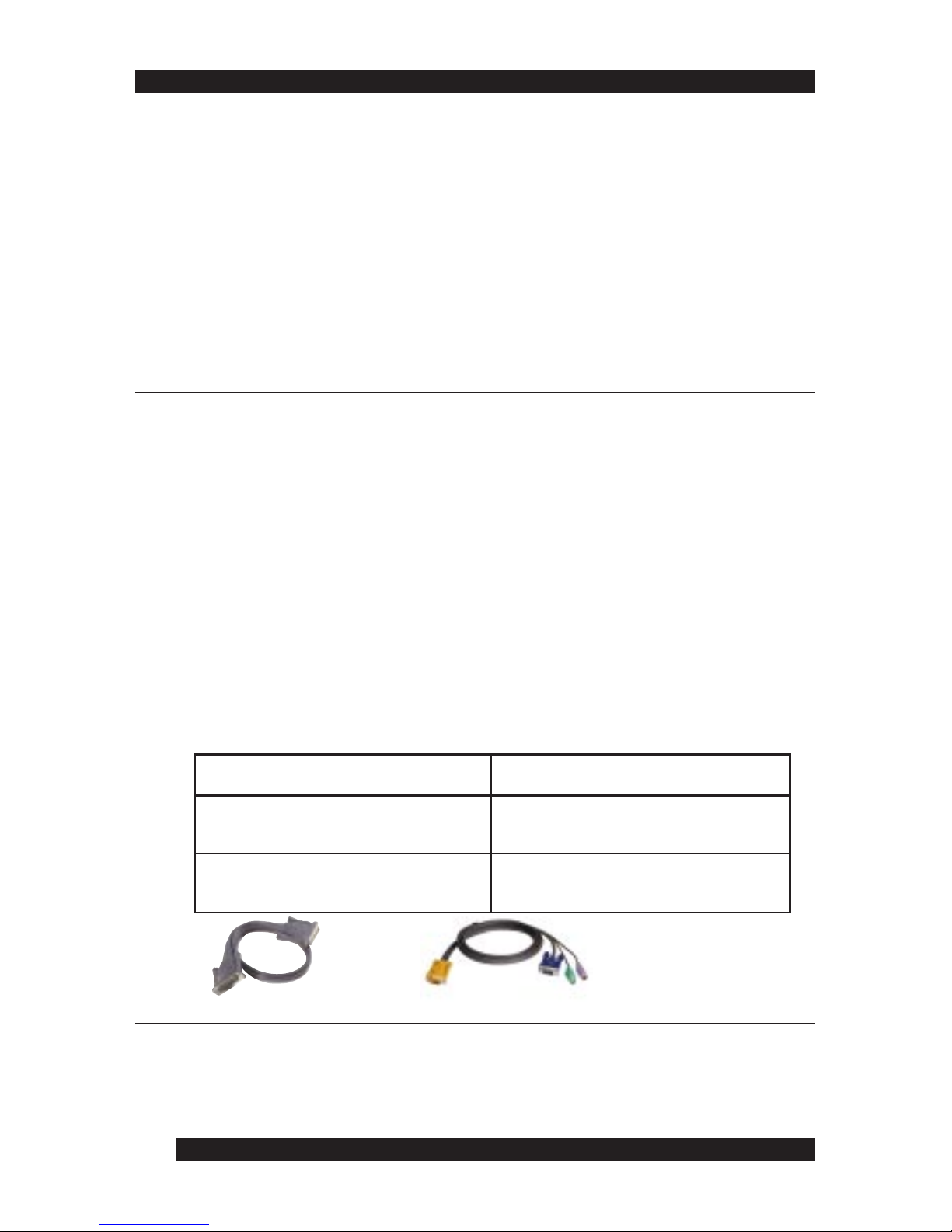
Cables
This section details the required hardware components for successful
installation and use of the KL0116.
Substandard cables may damage the connected devices or degrade overall
performance. For optimum signal integrity and to simplify the layout,
Altusen strongly recommends using the high quality Altusen Custom
Cable sets shown and described below:
KC1700, KC1701
• For MACs, a USB to PS/2 converter is required (purchased separately).
The video resolution needs to be set to either 800 x 600, or 1024 x 768.
• For Linux systems, the mouse needs to be set as a 2-button PS/2 mouse.
KC5202P, KC5203P
NOTE:
1. The KL0116 does not support serial mice. You cannot use Serial-to-PS/2 adapters
with the cables.
2. If your computer uses an AT style keyboard socket you must purchase a PS/2-toAT keyboard adapter in order to plug the cable into the computer’s keyboard port.
noitcnuFrebmuNtraPSC
ysiaD(hctiwSMVKothctiwSMVK
)gniniahC
)teef2(m6.0-0071CK
)teef6(m8.1-1071CK
retupmoCothctiwSMVK)teef6(m8.1-P2025CK
)teef01(m0.3-P3025CK
Cable Part Number
15
13
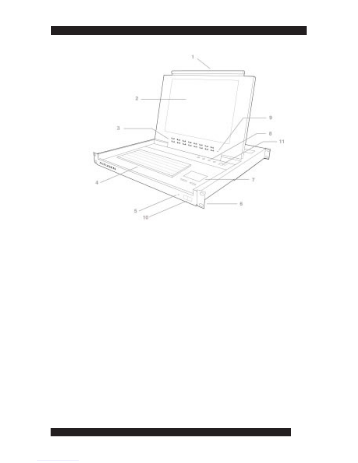
KL0116 Front View
1. Handle
• Pull the handle to slide the KVM module out. Push to slide the module in.
2. LCD Screen
• After sliding the KVM module out, flip the cover to access the LCD monitor.
3. Port LEDs
• Each port LED provides status information about corresponding CPU ports. The top
LED row corresponds to Port 1- 8 and the bottom LED row to Ports 9 - 16. Each Port
consists of a left and right LED pair: On Line LED (left port) and Selected Port LED
(right port). The following describes the LED light indicators:
- A GREEN On Line LED indicates the corresponding attached computer port is
up and running
- A RED Selected LED indicates the corresponding attached computer has the KVM
focus. Under normal conditions, the LED is steady. When accessing its port under
Auto Scan Mode (see page 21) the LED flashes.
- Each time the KL0116 powers on, the Switch performs a self-test. The On Line and
Selected LEDs blink once in succession during the self-test.
4. Keyboard
5. Power LED
• The Power LED lights blue when the KL0116 powers up and is ready to operate
6. Rack Mounting Brackets
• Rack mounting brackets are included to secure the chassis to a system rack

16
14
KL0116 Front View cont.
7. Touchpad
8. LCD Display Controls
NOTE: See the LCD Display Quick Reference Guide (provided with this package) for details
9. Reset Switch
• Press the recessed Reset switch with a thin oblect (the end of a paper clip or ballpoint
pen) to perform a system reset
10. Lock
• Set to the locked position to prevent the unit from sliding out while moving the rack
11. Remote Console Control
• Use the far right button to toggle the KVM focus between the local console (built-in
LCD display, keyboard and touchpad) and remote console (external). (See Chapter 6 for
more information)
• The local and Remote LEDs indicate the operating status of the local and remote KVM
consoles (See page 45 for more information).
17
15
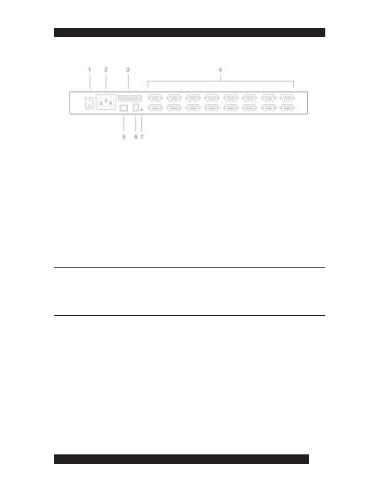
KL0116 Back View
1. Power Switch
• Turn on the KL0116 with the standard rocker power switch.
2. Power Socket
• Plug the AC power cord in the power socket.
3. Daisy Chain Port
• For Daisy Chained installations, plug the daisy chain cable into the Daisy Chain port.
The KL0116 only has a Chain Out port and is used as the master on the chain.
4. CPU Port Section
• The cables that link to the computers plug in here. Only cables specifically designed to
work with this switch can plug into the CPU port section. Do NOT use ordinary 15 pin
VGA connector cables to link computers to these ports.
NOTE: For detailed information on cables, see page 12.
5. Remote Console Port
• If you choose to use a remote console, its cable plugs into this RJ-45 connector. When a
remote and local console are present, both can access the switch.
NOTE: For detailed information on using the KL0116 with a remote console, see Chapter 6.
• The Select button located at the far right of the LCD display controls (see page 14),
toggles the KVM focus between the local (the built-in LCD display, keyboard and
touchpad) and remote (external) consoles.
6. Firmware Upgrade Port
• The Firmware Upgrade Cable plugs into the Firmware Upgrade Port’s RJ-11 connector
and transfers firmware upgrade data from the administrator’s computer to the KL0116.
7. Firmware Upgrade Recovery Switch
• This switch is in the NORMAL position during normal operation or while performing a
firmware upgrade. If the firmware upgrade operation does not successfully complete,
slide the switch to the RECOVER position; power off and restart to return the switch to
its former firmware state. When finished, slide the switch to the NORMAL position and
attempt the firmware upgrade again or use the switch with the original firmware.

18
Before you begin, turn off power to all devices with which you plan to connect.
To prevent damage to your equipment due to static electric discharge, properly
ground all devices on the installation. Consult your dealer for technical details if
necessary.
Chapter
22
22
2
Installation
Disregard the Daisy Chain ports at this time. Use Daisy Chain Ports for daisy chaining
the KL0116 to additional KH0116 switches. See the next section in this chapter for
more information on daisy chaining.
NOTE:
2. Plug the power adapter cable into the KL0116’s Power Socket, and then plug
the power adapter into an AC power source.
3. Turn on the power to the KL0116.
4. Turn on the power to the computers.
Daisy Chaining
To control even more computers, up to 31 additional switches can be daisy
chained down from the first KVM switch. In a complete installation, you can
control up to 512 computers from the KL0116’s integrated slide-out console.
16
Single Station Installation
In a Single Stage installation, no additional switches are daisy chained down from
the first unit. To set up a single stage installation, do the following:
1. Use KVM cable sets (as described in the Cables section on page 12), to
connect any available CPU Port to the Keyboard, Video and Mouse ports of
the computer you are installing.
 Loading...