

Page 1
ALTV1224C
- BAT +
AC AC
DC
AC
1 2 3 4
ON
MAIN FUSE
ON OFF
N
C
OMM ON POW ER OUT P UTS
P
F
USE D P OWE R O UTP UTS
1 2 3 4 5 6 7 8
D1
INPUT
R1
LED
XFMR
AC Outputs
DC Outputs
Black
Lead
W
hite
Lead
115VAC,
50/60 Hz
I
nput,
1.52 amp
MAIN FUSE
ON OFF
N
COM MON PO WER OU T PUT S
P
FUS ED POW ER OUT PUT S
1 2 3 4 5 6 7 8
D1
INPUT
R1
LED
+
DCINPUT -
AC/DC Dual Output Power Supply
Overview:
The Altronix ALTV1224C AC/DC Dual Output Power Supply is designed to provide both 12VDC and 24VAC outputs
w
here a combination of both AC and DC outputs are required. Provides eight (8) 12VDC outputs with a total current of
3.5 amp and eight (8) 24VAC outputs with a total current of 3.5 amp.
Specifications:
• 115VAC 50/60 Hz, 1.52 amps.
•
7 amp total output current.
• 16 individually fused outputs.
• 3.5 amp supply current at 12VDC (Fig. 1).
•
Eight (8) outputs @ 12VDC.
• 3.5 amp supply current at 24VAC (Fig. 1).
•
Eight (8) outputs @ 24VAC.
• Output fuses are rated at 3.5 amp / 250VAC.
• Main fuses are rated at 5 amp / 250VAC (Fig. 1).
• Surge suppression.
•
AC /DC power LED indicator.
• Power ON/OFF switch.
• Spare fuses included.
• Unit maintains camera synchronization.
• Ease of installation saves time and
eliminates costly labor.
Enclosure dimensions: 15.5"H x 12"W x 4.5"D
Optional available with 220VA
C input order
model # ALTV1224C/220.
Installation Instructions:
Wiring methods shall be in accordance with the
National Electrical Code/NFPA 70/NFPA 72/ANSI,
and with all local codes and authorities ha
ving jurisdiction. Product is intended for indoor use only.
1. Mount unit in desired location. Mark and predrill holes in the wall to line up with the top two keyholes in the
enclosure. Install two upper fasteners and screws in the wall with the screw heads protruding. Place the enclosure’s
upper keyholes over the two upper screws, level and secure. Mark the position of the lower two holes. Remove the
enclosure. Drill the lower holes and install the three fasteners. Place the enclosure’s upper keyholes over the two
upper screws. Install the two lower screws and make sure to tighten all screws (Enclosure Dimensions, pg
Secure enclosure to earth ground.
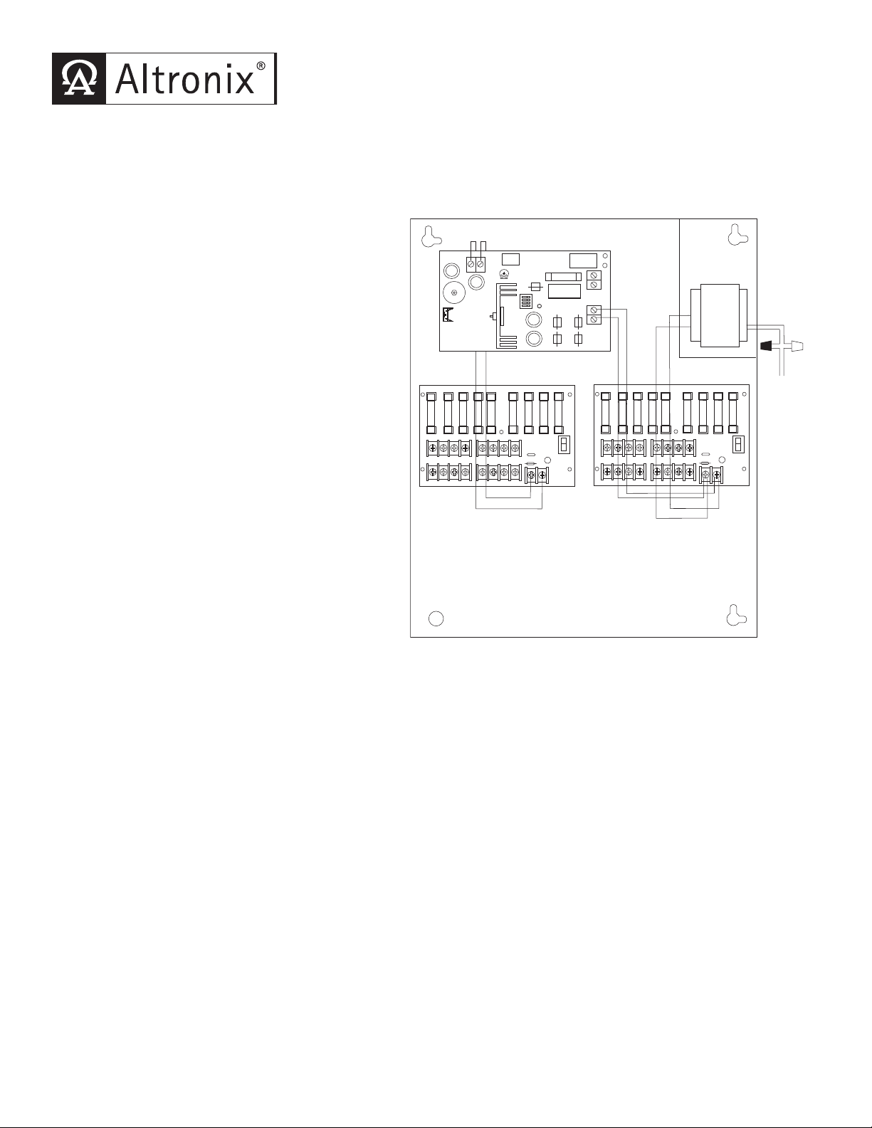
2. Slide switch SW1 (Fig. 1) to OFF position.
3. Connect the
two black and white flying leads of the transformers (Fig 1).
4. Measure output voltage before connecting devices. This helps avoid potential damage.
5.
Connect devices to output terminals using the following procedure (Fig. 1).
Connect each DC de
carefully observing correct polarity.
Connect each AC device to terminal pairs on AC output board 1 thru 8, marked [P (+) and N (-)].
6. When batteries are being used the DC output voltage must be adjusted by turning the trim pot VR1 (Fig 1)
clockwise to increase the output voltage to 13.7 VDC. Connect battery to terminals marked [- BAT +] (Fig. 1)
on the unit (battery leads included).
CAUTION: Determine the maxim
the output voltage. When the battery charging voltage is increased the DC output voltage will also increase.
AC (115 VAC 50/60 Hz) to the
vice to terminal pairs on DC output board 1 thru 8, marked [P (+) and N (-)]
um operating voltage of the equipment being powered before adjusting
7. Slide switch SW1 (Fig. 1) to ON position.
8.
Green LED on the PD8’s will illuminate when power is present.
9. Upon completion of wiring, secure enclosure door with screws (supplied).
Fig. 1
. 2).
Page 2

WARNING: To reduce the risk of fire or electric shock, do not expose the unit to rain or moisture. This
1.285
1.285
installation should be made by qualified service personnel and should conform to all local codes and in
accordance with the National Electrical Code.
Terminal Identification:
SMP5
Terminal Legend Function/Description
AC/ AC Low voltage AC input (24VAC / 175VA). Altronix part # T24175.
+ DC -
- BAT + Stand-by battery connections. Maximum charge rate .5 amp.
PD8 (DC Output)
1P - 8P Positive DC power outputs.
1N - 8N Negative DC power outputs.
PD8 (AC Output)
1P - 8P AC power outputs.
1N - 8N AC power outputs.
Enclosure Dimensions:
15.5"H x 12"W x 4.5"D
12VDC @ 3.5 amp total supply current.
Altronix is not responsible for any typographical errors. Product specifications are subject to change without notice.
140 58th Street, Brooklyn, New York 11220 USA, 718-567-8181, fax: 718-567-9056
web site: www.altronix.com, e-mail: info@altronix.com, Made in U.S.A.
IIALTV1224C - Rev. 113004 A05J
MEMBER
 Loading...