

Page 1

AL600ULXD - Power Supply/Charger
Overview:
The AL600ULXD power supply converts a 115VAC or 230VAC / 50/60Hz input, to a 12VDC or 24VDC non-power
limited output, (see specifications).
Specifications:
• UL Listed fire and access control power supply (UL1481, UL294).
• Switch selectable 12VDC or 24VDC non-power limited output.
• Input 115VAC / 60Hz, 1.9 amp or 230VAC 50/60Hz, .95 amp.
• Maximum charge current .7 amp.
• 6 amp continuous supply current at 12VDC / 24VDC.
• Filtered and electronically regulated output.
• Built-in charger for sealed lead acid or gel type batteries.
• Automatic switch over to stand-by battery when AC fails.
• AC input and DC output LED indicators.
• AC fail supervision (form "C" contacts).
• Low battery and battery presence supervision (form "C" contacts).
• Thermal overload protection.
• Short circuit protection.
• Unit is complete with power supply, enclosure, cam lock
and open frame transformers.
• Includes battery leads.
Enclosure Dimensions: 15.5”H x 12”W x 4.5”D
Note: Enclosure accommodates up to tw
o (2) 12AH batteries
Power Supply Voltage Output Selections:
Output Switch Position
12VDC SW 1 Closed
24VDC SW1 Open
Stand-by Specifications:
Output 4 hr. of Stand-by & 24 hr. of Stand-by & 60 hr. of Stand-by &
5 Minutes of Alarm 5 Minutes of Alarm 5 Minutes of Alarm
12VDC / 40
24VDC / 12 AH Battery Stand-by = 200mA
24VDC / 40 AH Battery Stand-by = 6.0 amp Stand-by = 1.0 amp Stand-by = 300mA
AH Batter
y
Stand-by = 6.0 amp Stand-by = 1.0 am Stand-by = 300mA
m = 6.0 amp
m = 6.0 amp
m = 6.0 amp
Alar
Alarm = 6.0 amp Alarm = 6.0 amp Alarm = 6.0 amp
Alar
Alarm = 6.0 amp
Alar
Installation Instructions:
The AL600ULXD should be installed in accordance with article 760 of The National Electrical Code or NFPA 72 as
well as all applicable Local Codes.
Mount the
1.
2. Connect input power from a separate unswitched AC circuit to the transformers. Secure green wire lead to
th g
ear
or 115V
F
or 230V
F
eep po
K
Battery
AL600ULXD in desired location.
round.
C input:
A
C input: Connect Blue and Yellow leads of transformer 1 together. Connect Blue and Yellow leads of
A
er limited wiring separate from non-power limited wiring (115VAC 50/60Hz or 230 50/60Hz Input,
w
ir
W
(F
es).
. 1).
ig
w and White leads from transformer primary to neutral.
ello
Connect
Connect Blue and Black leads from transformer primary to line
transfor
Connect Black lead from both transformers to line
Minim
Y
mer 2 to
um .25” spacing m
gether
. Connect
ust be pr
White lead from both transfor
(Fig. 3).
ovided.
(Fig. 2).
mers to neutral.
Page 2
3. Measure output voltage before connecting devices. This helps avoid potential damage.
115 VAC input
50/60 Hz, 1.9 amp
230VAC input
50/60 Hz, .95 amp
Green
Lead
(ground)
XFMR
XFMR
5
4
3
2 1
BLACK
YELLOW
BLUE
WHITE
LINE
NEUTRAL
5
4
3
2 1
BLACK
YELLOW
BLUE
WHITE
230VAC Input
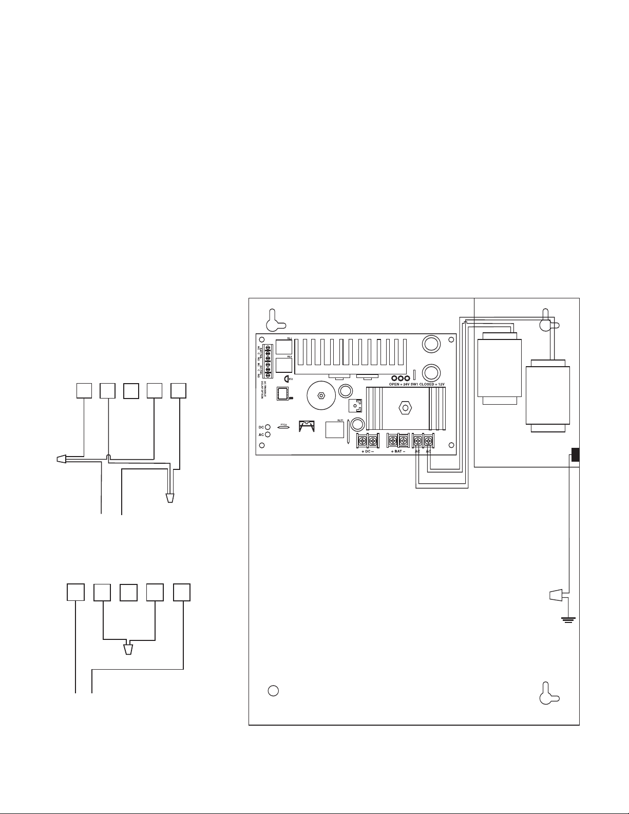
4. Connect devices to be powered to terminals marked [- DC +] (Fig. 1).
5
. For Access Control applications, batteries are optional. When batteries are not used a loss of AC will result in the
loss of output voltage. When the use of stand-by batteries is desired, they must be lead acid or gel type.
Connect battery to terminals marked [+ BAT -]
(Fig. 1) (battery leads included). Use two (2)
12VDC batteries connected in series for 24VDC operation.
6. Connect appropriate trouble reporting devices to AC Fail & Low battery
(Fig. 1) supervisory
relay outputs marked [N.C., C, N.O.]. Use 22 AWG to 18 AWG for AC Fail / Low Battery reporting. AC Failure
will report in 5 minutes. For a 6 hour delay on reporting cut resistor R1
(Fig. 1).
Maintenance:
Unit should be tested at least once a year for the proper operation as follows:
Output Voltage Test: Under normal load conditions, the DC output voltage should be checked for proper voltage level
(Power Supply Voltage Output Specifications Chart).
Battery Test: Under normal load conditions check that the battery is fully charged, check specif ied voltage both
at battery terminal and at the board terminals marked [- BAT +] to insure there is no break in the battery
connection wires.
Note: Maximum charging current under discharges is .7 amp.
Note: Expected battery life is 5 years, however it is recommended changing batteries in 4 years or less if needed.
Fig. 2 - 115VAC Input
115VAC Input
Fig. 3 - 230VAC Input
230VAC Input
Altronix is not responsible for any typographical errors. Product specifications are subject to change without notice.
Fig. 1
Page 3

LED Diagnostics:
R
ed (DC) Green (AC) Power Supply Statu
ON ON Normal operating condition
ON OFF Loss of AC, Stand-by battery supplying power
OFF ON No DC output
OFF OFF Loss of AC. Discharged or no stand-by battery. No DC output
s
Terminal Identification:
Terminal Function/Description
Legend
AC / AC Low voltage AC input (28VAC / 200VA).
Two (2) Altronix part # T2885D.
+ DC - 12VDC / 24VDC @ 6 amp continuous non-power limited output.
AC FAIL Used to notify loss of AC power, e.g. connect to audible device or alarm
.C., N.O. panel. Relay normally energized when AC power is present.
C, N
Contact rating 1 amp @ 28VDC
Low Battery Used to indicate low battery condition, e.g. connect to alarm panel.
.C., C Relay normally energized when DC power is present.
., N
N.O
Contact rating 1 amp @ 28VDC
- BAT + Stand-by battery connections. Maximum charge rate .7 amp.
Page 4

1.285
1.285
Enclosure Dimensions:
15.5”H x 12”W x 4.5”D
MEMBER
Altronix Cor
140 58th Street, Brookl
web site: www.altronix.com, e-mail: info@altronix.com, Lifetime Warranty, Made in U.S.A.
IIAL600ULXD - Rev. 013103 L03D
p.
w York 11220 USA, 718-567-8181, fax: 718-567-9056
yn, Ne
 Loading...