

Page 1

AL600UL3X - Triple Output Access Control
Power Supply/Charger
Rev. 010202
Overview:
The AL600UL3X triple output access control power supply/charger is specifically designed for use with access
control systems and accessories. The AL600UL3X converts a 115VAC / 60Hz input into three individually circuit
breaker protected 5VDC, 12VDC and 24VDC regulated outputs (see specifications).
Specifications:
•ULListed for Access Control Systems and for Fire protective Signaling Systems (UL294 & UL1481).
• NYC Department of Buildings Approved (MEA).
•California State Fire Marshal Approved (CSFM).
• Class 2 rated (5VDC and 12VDC outputs).
• Input 115VAC / 60Hz, 1.9 amp.
•1.75 amp continuous supply current @ 5VDC.
•1.75 amp continuous supply current @ 12VDC.
•3 amp continuous supply current @ 24VDC.
• Filtered and electronically regulated outputs, 100mV peak output voltage ripple.
• Maximum charge current .7 amp.
• Built-in charger for sealed lead acid or gel type batteries.
• Automatic switch over to stand-by battery when AC fails.
• Thermal and short circuit protection with auto reset.
• AC input and DC output LED indicators.
• AC fail supervision (form "C" contact).
• Battery fail and battery presence supervision (form "C" contact).
• Power supply is complete with enclosure, cam lock, and battery leads.
• Enclosure accommodates up to two (2) 7AH batteries.
Enclosure dimensions: 15.5"H x 12"W x 4.5"D
Stand-by Specifications (current is specified on AL3XB input):
Output 4 hr. of Stand-by & 24 hr. of Stand-by & 60 hr. of Stand-by &
5 Minutes of Alarm 5 Minutes of Alarm 5 Minutes of Alarm
24VDC / 12 AH Battery Stand-by = 200mA
Alarm = 6.0 amp
24VDC / 40 AH Battery Stand-by = 6.0 amp Stand-by = 1.0 amp Stand-by = 300mA
Alarm = 6.0 amp Alarm = 6.0 amp Alarm = 6.0 amp
Installation Instructions:
The AL600UL3X should be installed in accordance with The National Electrical Code and all applicable Local
Regulations.
1. Mount the AL600UL3X in desired location. It is recommended to first review the following tables for screw
terminals, switch selection and LED status indications. This will greatly facilitate installation hook-up.
Carefully review:
Stand-by Specifications (pg. 1) Terminal Identification Table (pg. 3)
LED Diagnostics (pg. 3)
Note: It is important to measure output voltage before connecting devices. This helps avoid potential damage
2. Connect AC power (115VAC 50/60Hz to terminals marked [L, G, N]. Use 18 AWG or larger for all
power connections. Secure green wire lead to earth ground (Fig. 1, pg. 3).
Keep power limited wiring separate from non-power limited wiring (115VAC / 60Hz Input, Battery Wires).
Minimum .25” spacing must be provided.
3. Connect devices to be powered at 5VDC to the terminals marked [+ Out 3 - ] .
4. Connect devices to be powered at 12VDC to the terminals marked [+ Out 2 - ].
5. Connect devices to be powered at 24VDC to the terminals marked [+ Out 1 - ].
Altronix is not responsible for any typographical errors. Product specifications are subject to change without notice.
Page 2
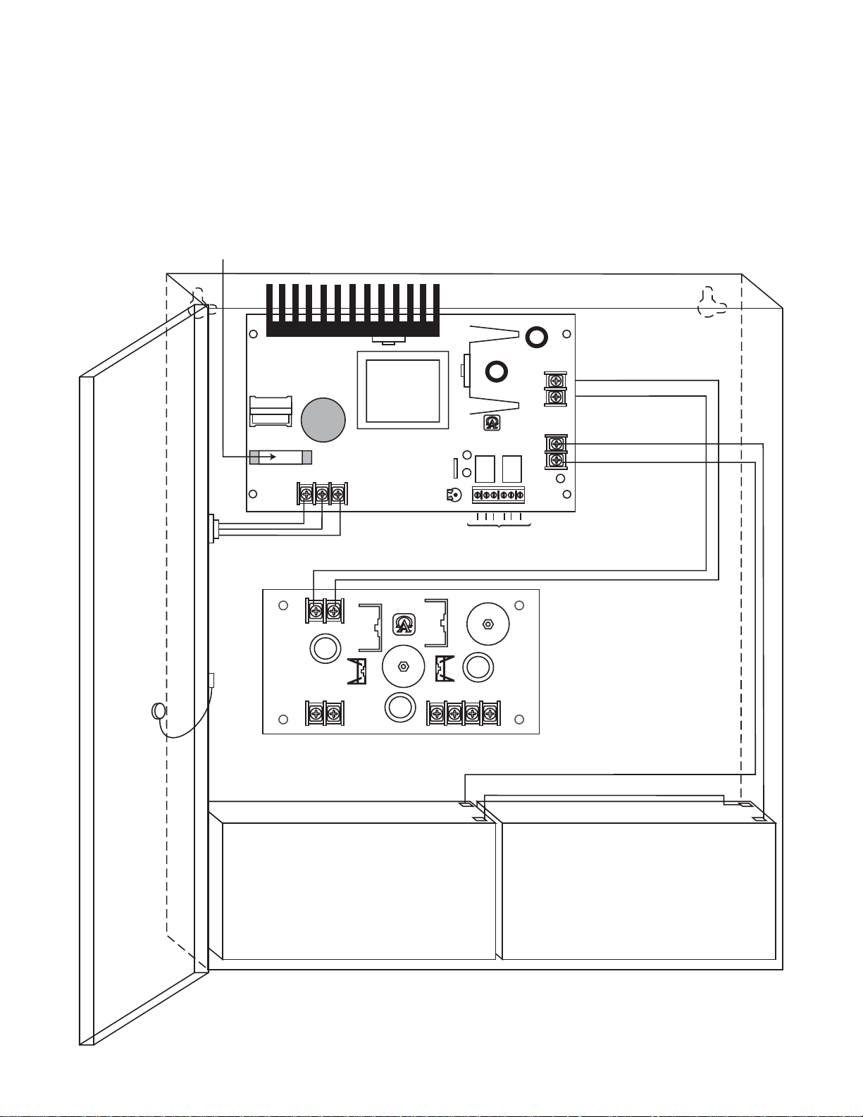
6. Connect two (2) 12V Stand-by batteries.
+ DC ---
AL600ULXB
ALTRONIX CORP.
BKLYN, N.Y. 11220
MADE IN USA
BAT FAIL
NC C NO NC C NO
+ BAT ---
DC
24V - OPEN
12V - CLOSED
AC FAIL
L G N
AC
BAT
Battery and AC Supervision Circuit (power limited). Use separate
knockout. Keep 1/4" away from non power limited wiring
CAUTION: De-energize unit prior to servicing. For continued protection
against fire hazard replace fuse with the same type and rating 3.5A, 250V.
Replace fuse cover before energizing.
Battery 1
Battery 2
Battery connection (non power limited)
Switch Position:
24VDC = SW1 OPEN
12VDC = SW1 CLOSED
115 power mains
(non power limited)
Door
Wire Strap
(from
Enclosure
to Door)
ALX3B
ALTRONIX CORP.
BKLYN, NY 11220
MADE IN U.S.A.
+ OUT2 --- + OUT3 ---+ OUT1 ---
+ INPUT1 ---
Note: For Access Control applications batteries are optional. When batteries are not used a loss of AC will result in
the loss of output voltage. Batteries must be lead acid or gel type if used. Tw o (2) 12V Stand-by batteries
connected in series to terminals marked [+ BAT --] (Fig. 1 , pg. 3).
7. It is required connect supervisory trouble reporting devices to outputs marked [AC FAIL, LOW BAT] (Fig. 1 , pg. 3).
Use 22 AWG to 18 AWG for AC Fail & Low Battery reporting. AC Failure will report in 5 minutes.
Fig. 1
2
Page 3

Maintenance:
Unit should be tested at least once a year for the proper operation as follows:
Output Voltage Test: Under normal load conditions, the DC output voltage should be checked for proper voltage level
(see power supply output specifications table).
Battery Test: Under normal load conditions check that the battery is fully charged, check specified voltage at
the battery terminals and at the board terminals marked [- BAT +] to insure that there is no break in the battery
connection wires.
Note: Maximum charge current under discharge is 0.7 amp.
Note: Expected battery life is 5 years, however it is recommended changing batteries in 4 years or less if necessary.
LED Diagnostics:
AL600ULXB - Power Supply
LED
Red (DC) Green (AC) Power Supply Status
ON ON Normal operating condition.
ON OFF Loss of AC, Stand-by battery supplying power.
OFF ON No DC output. Short circuit or thermal overload condition.
OFF OFF No DC output. Loss of AC. Discharged battery.
Terminal Identification:
AL600ULXB - Power Supply
Terminal Function/Description
Legend
L, G, N Connect 115VAC to these terminals: L to hot, N to neutral, G to ground.
+ DC - 24VDC @ 6 amp continuous non-power limited output. Supplies power to AL3XB.
AC FAIL Used to notify loss of AC power, e.g. connect to audible device or alarm panel. Relay
C, N.C., N.O. normally energized when AC power is present. Contact rating 1 amp @ 28VDC.
AC or brownout fail is reported within 1 minute of event. To delay reporting of up to
6 hrs., cut “AC delay” jumper and reset power to unit.
BAT FAIL Used to indicate low battery condition, e.g. connect to alarm panel. Relay normally
N.O., N.C., C energized when DC power is present. Contact rating 1 amp @ 28VDC.
A removed battery is reported within 5 minutes. Battery reconnection is reported
within 1 minute.
Low battery threshold is set @ approximately 21VDC.
- BAT + Stand-by battery connections. Maximum charge rate .7 amp.
AL3XB - Power Output Module
Terminal Legend Function/Description
-INPUT + 24VDC from power supply (AL600ULXB).
- OUT 1 + 24VDC @ 3 amp continuous power limited output.
- OUT 2 + 12VDC @ 1.75 amp continuous power limited output.
- OUT 3 + 5VDC @ 1.75 amp continuous power limited output.
3
Page 4

Enclosure Dimensions:
15.5"H x 12"W x 4.5"D
Altronix Corp.
140 58th Street, Brooklyn, New York 11220 USA, 718-567-8181, fax: 718-567-9056
4
web site: www.altronix.com, e-mail: info@altronix.com, Lifetime Warranty, Made in U.S.A.
MEMBER
 Loading...