

Page 1

AL400X220 Series
Power Supply/Charger
Installation Guide
Models Include:
• AL400X220
- Single Output
• AL400PD4220 • AL400PD4CB220
- Four (4) Fused Outputs - Four (4) PTC Outputs
• AL400PD8220 • AL400PD8CB220
- Eight (8) Fused Outputs - Eight (8) PTC Outputs
• AL400XPD16220 • AL400XPD16CB220
- Sixteen (16) Fused Outputs - Sixteen (16) PTC Outputs
For a red enclosure, add an “R” suffix to the part # e.g. AL400PD8R220
Rev. 111203
Page 2

Overview:
The AL400X220 is a power supply that converts a 220VAC 50/60Hz input, to a 12VDC or 24VDC regulating output,
(see specifications below).
The AL400X220 is the base power supply unit for the multi-output power supply/charger series: AL400PD4220,
AL400PD4CB220, AL400PD8220, AL400PD8CB220, AL400XPD16220, AL400XPD16CB220
(Refer to AL400X220 Series Power Supply Configuration Reference Chart below).
AL400X220 Series Power Supply Configuration Reference Chart:
Model Number
Altronix
AL400X220 -1--43
AL400PD4220 PD4A
AL400PD4CB220 PD4ACB 4 - x 2.5 2.5
AL400PD8220 PD8A 8 x - 3.5 3
AL400PD8CB220 PD8ACB 8 - x 2.5 2.5
AL400XPD16220 16 x - 3.5 3
AL400XPD16CB220 16 - x 2.5 2.5
Do not e
xceed total output rating of 4 amp @ 12VDC or 3 amp @ 24VDC per unit.
Distribution
Accessory Power
Two (2)
PD8A
Two (2)
PD8ACB
Module(s)
Number of Outputs
Fused Outputs
4 x - 3.5 3
12VDC Per Output
PTC Outputs
Current (amp)
24VDC Per Output
Current (amp)
Specifications:
Input:
• Input 220VAC 50/60Hz, 1.45 amp.
• AC input and DC output LED indicators.
Output:
12VDC or 24VDC selectable output.
•
• 4 amp total supply current at 12VDC
rent at 24VDC.
or 3 amp total suppl
• Filtered and electronically regulated outputs.
• Short circuit and thermal overload protection.
y cur
Battery Backup:
• Built-in charger for sealed lead acid or gel type batteries.
• Automatic switch o
AC fails.
Maximum charge current .7 amp.
•
• Zero voltage drop when switched over to battery backup.
Supervision:
• AC fail supervision (form "C" contacts).
w batter
Lo
•
Batter
•
Additional Features:
• Power supply, enclosure, cam lock and battery leads.
• All models are available in red enclosure
(add an “R” suffix to the part # e.g. AL400PD8220).
ver to stand-by battery when
y super
y presence super
vision (form "C" contacts).
vision (for
m “C” contacts).
- 2 - AL400X220series
Page 3
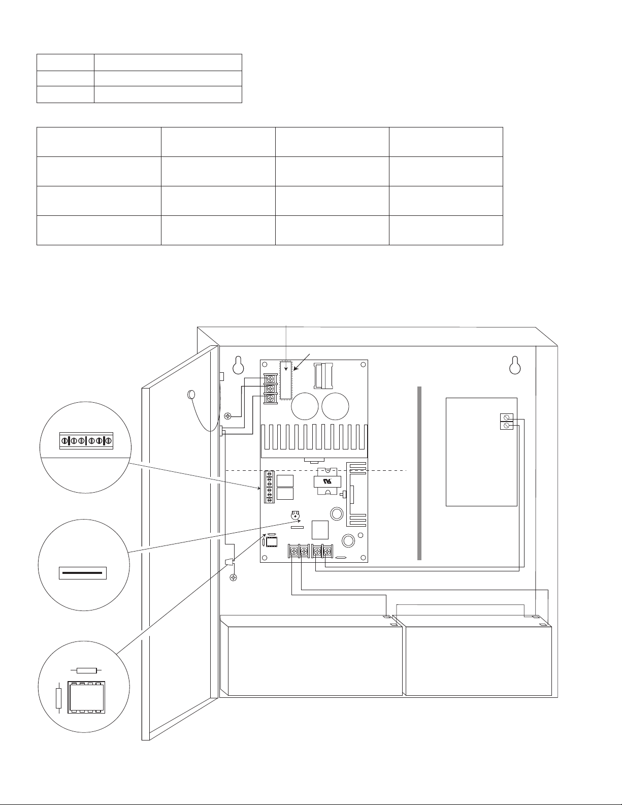
P
--- DC
+
L G N
PTC3
NC C NO NC C NO
+
BAT ---
DC
24V - OPEN
12V - CLOSED
AC FAIL
RL2
BAT FAIL
RL1
RL3
SW1
Fuse
Door
CAUTION: De-energize unit prior to servicing. For continued protection
against risk of electric shock and fire hazard replace fuse with the same type
and rating 3.5A, 250V. Replace fuse cover before energizing.
Do not expose to rain or moisture.
Green
Lead
Battery connection (non power-limited)
Wire
Strap
(from
Enclosure
to Door)
220VAC
power mains
Battery & AC Supervision
Circuit
(power-limited)
F
use Cover
Power
Distribution
Module(s)
INPUT
Divider
24V - OPEN
12V - CLOSED
SW1
power-limited
NC C NO NC C NO
A
C FAIL
B
AT FAIL
Green
Lead
CAUTION: When power supply board is set for 12VDC use only one (1) 12VDC
stand-by battery.
Keep power-limited wiring separate from non-power limited. Use minimum .25" spacing.
12VDC Rechargeable Battery
(optional)
12VDC Rechargeable Battery
(optional)
AC Delay
AC Delay
ower Supply Output Specifications:
Output Switch Position
12VDC SW1 - CLOSED (Fig. 1b)
24VDC SW1 - OPEN (Fig. 1b)
Stand-by Specifications (total current shown):
Output
12VDC / 40AH Battery
4 hr. of Stand-by &
5 Minutes of Alarm
Stand-by = 4.0 amp
Alarm = 4.0 amp
24VDC / 12AH Battery --------
24VDC / 40AH Battery
Stand-by = 3.0 amp
Alarm = 3.0 amp
Fig. 1
AL400X220
AL400PD4220
AL400PD4CB220
AL400PD8220
AL400PD8CB220
Fig. 1a
24 hr. of Stand-by &
5 Minutes of Alarm
Stand-by = 1.0 amp
Alarm = 4.0 amp
Stand-by = 200mA
Alarm = 3.0 amp
Stand-by = 1.0 amp
Alarm = 3.0 amp
60 hr. of Stand-by &
5 Minutes of Alarm
Stand-by = 300mA
Alarm = 4.0 amp
--------
Stand-by = 300mA
Alarm = 3.0 amp
Fig. 1b
Fig. 1c
AL400X220series - 3 -
Page 4

Power Distribution
Module
B
attery and AC
Supervision Circuit
(power limited)
Green Lead
Battery connection (non-power limited)
Switch Position:
24VDC = SW1 OPEN
12VDC = SW1 CLOSED
Door
W
ire Strap
(from
Enclosure
t
o Door)
2
20VAC power mains
(non-power limited)
D
ivider
--- DC
+
L G N
PTC3
NC C NO NC C NO
+
BAT ---
DC
24V - OPEN
12V - CLOSED
AC FAIL
RL2
BAT FAIL
R
L1
RL3
SW1
Class 1
Fuse
Cover
CAUTION: De-energize unit prior to servicing. For continued protection against risk of
electric shock and fire hazard replace fuse with the same type and rating 3.5A, 250V.
Replace protective cover before energizing unit. Do not expose to rain or moisture.
3
.5A
250V
Green Lead
CAUTION: When power supply board is set for 12VDC use only one (1) 12VDC
stand-by battery.
12VDC Rechargeable Battery
(optional)
12VDC Rechargeable Battery
(optional)
Power Distribution
Module
Fig. 2
AL400XPD16220
A
L400XPD16CB220
Installation Instructions:
iring methods shall be in accordance with the National Electrical Code/NFP
W
A 70/NFP
A 72/ANSI, and with all local
codes and authorities having jurisdiction. Product is intended for indoor use only.
1. Mount unit in desired location. Mark and predrill holes in the wall to line up with the top two keyholes in the
enclosure. Install two upper fasteners and screws in the wall with the screw heads protruding. Place the enclosure’s
yholes over the two upper screws, level and secure. Mark the position of the lower two holes. Remove the
upper k
enclosure. Drill the lower holes and install the three fasteners. Place the enclosure’s upper keyholes over the two
upper scre
The po
2.
e
ws. Install the two lower screws and make sure to tighten all screws
er supply is pre-wired to the ground (chassis). Connect main incoming ground to the provided green
w
losure Dimensions, pg. 7-8).
(Enc
grounding conductor lead. Connect unswitched AC power (220VAC 50/60 Hz to terminals marked [L, G, N]
(Fig. 1, pg. 3 & Fig. 2, pg. 4). Use 14 AWG or larger for all power connections (Battery, DC output, AC input).
Use 22 AWG to 18 AWG for power-limited circuits (AC Fail/Low Battery reporting).
Keep power-limited wiring separate from non power-limited wiring (220VAC 50/60Hz Input, Battery Wires).
Minimum .25” spacing must be provided.
- 4 - AL400X220series
Page 5

3
. Set the unit to the desired DC output voltage by setting SW1(Fig. 1b, pg. 3)to the appropriate position
(Power Supply Voltage Output Selections Chart, pg. 3).
4
. Measure output voltage before connecting any devices to ensure proper operation. Improper or high voltage will
damage these devices. When servicing the unit, AC mains should be removed.
5. Connect devices to be powered:
a. For AL400X220 Power Supply connect devices to terminals marked [- DC +] (
b. For other Power Distribution Models connect devices to be powered to terminal pairs 1 to 4 marked
[1P & 1N thru 4P & 4N] (
carefully observing correct polarity.
6. For Access Control applications, batteries are optional. When batteries are not used a loss of AC will result in the
loss of output voltage. When the use of stand-by batteries is desired, they must be lead acid or gel type.
7. Connect appropriate signaling notification devices to AC FAIL & BAT FAIL
relay outputs.
Note: When used in fire alarm, burglar alarm or access control applications, “AC Fail” relay should be
utilized to visually indicate that AC power is on
8. Please insure that the cover is secured with the provided Key Lock.
Fig. 2a & 2b, pg. 6) or 1 to 8 marked [1P & 1N thru 8P & 8N] (Fig. 3a & 3b, pg. 6)
(Fig. 1c, pg. 3).
Fig. 1, pg. 3).
(Fig. 1a, pg. 3) supervisory
Wiring:
USE 14 AWG or larger for all power connections.
Note: Take care to keep power-limited circuits separate from non-power limited wiring (220VAC, Battery).
Maintenance:
Unit should be tested at least once a year for the proper operation as follows:
Output Voltage Test: Under normal load conditions, the DC output voltage should be checked for proper voltage level
(Power Supply Voltage Output Specifications Chart, pg. 3).
Battery
battery terminal and at the board ter
connection wires.
Note: Maximum charging current under discharges is .7 amp.
Note: Expected batter
Test:
Under nor
mal load conditions check that the battery is fully charged, check specified voltage both at
minals mark
y life is 5 years, however it is recommended changing batteries in 4 years or less if needed.
ed [+ BAT -] to insure there is no break in the battery
LED Diagnostics:
AL400XB220 - Power Supply Board
Red (DC) Green (AC) Power Supply Status
ON ON Normal operating condition.
ON OFF Loss of
OFF ON No DC output.
OFF OFF Loss of
AC, Stand-by battery supplying power.
C. Discharged or no stand-by battery. No Dc output.
A
Terminal Identification:
AL400XB220 - Power Supply Board
Terminal
Legend
L, G, N Connect 220VAC 50/60 Hz. to these terminals: L to hot, N to Neutral, G to ground.
-- DC + 12VDC @ 4 amp or 24VDC @ 3 amp continuous power-limited output.
AC Fail
NC, NC, NO
Bat Fail
NC, C, NO
--
T
A
B
+
Function/Description
Indicates loss of AC power, e.g. connect to audible device or alarm panel. Relay normally energized
when AC power is present. Contact rating 1 amp @ 28VDC.
Indicates low battery condition, e.g. connect to alarm panel. Relay normally energized when DC power
is present. Contact rating 1 amp @ 28VDC.
rent 1.2 amp.
Stand-b
y batter
y connections. Maximum char
ge cur
AL400X220series - 5 -
Page 6

LED Diagnostics:
L
ED
F
1 F2 F3 F4
1
P
1N
2P
2N
3P
3N
4P
4N
DC Output to devices
1P-4P Power Outputs,
1N-4N Common Outputs
)
)
From Power Supply
Board
(Factory Installed)
Replace fuses with the same type and rating 3.5A, 250V.
INPUT
LED
F
1 F2 F3 F4
POWER OUTPUTS
1P
1N
2P
2N
3P
3N
4P
4N
DC Output to devices
1P-4P Power Outputs,
1N-4N Common Outputs
From Power Supply
Board
(Factory Installed)
( )
N
CO MM ON PO WE R O UT PU TS
P
FU SE D PO WE R O UTP UT S
1 2 3 4 5 6 7 8
D1
INPUT
R1
LED
From Power Supply
Board
(Factory Installed)
Replace fuses with the same type and rating 3.5A, 250V.
DC Output to devices
1P-8P Power Outputs,
1N-8N Common Outputs
( )
N
CO MM ON PO WE R O UT PU TS
P
FU SE D PO WE R O UTP UT S
1 2 3 4 5 6 7 8
D1
INPUT
R1
LED
From Power Supply
Board
(Factory Installed)
DC Output to devices
1P-8P Power Outputs,
1N-8N Common Outputs
( )
PD4A/PD4ACB/PD8A/PD8ACB - Power Distribution Module
Green (AC) Power Distribution Module Status
ON Normal operating condition.
OFF No Power Output.
Terminal Identification:
PD4A/PD4ACB/PD8A/PD8ACB - Power Distribution Module
Terminal Legend
PD4A/PD4ACB
Terminal Legend
PD8A/PD8ACB
Function/Description
1P to 4P 1P to 8P Normal operating condition.
1N to 4N 1N to 8N No Power Output.
Power Distribution Module(s):
Fig. 3a
Fig. 3b
Fig. 4a
- 6 - AL400X220series
Fig. 4b
Page 7

Enclosure Dimensions:
• AL400X220
• AL400PD4220
• AL400PD4CB220
• AL400PD8220
• AL400PD8CB220
13.5”H x 13”W x 3.25”D
AL400X220series - 7 -
Page 8

Enclosure Dimensions:
12.230"
15.500"
1.100"
0.910"
1.100"
0.910"
0.790"
1.100"
1.500"
1.250"
5.000"
1.250"
1.500"
4.615"
4.615"1.500"
1.750"
1.500"4.615"
4.615"1.500"
1.750"
4.500"4.500"
1.250"
1.500"
5.000"
2.000"
2.000"
1.250"
1.375"
1.125"
• AL400XPD16220
• AL400XPD16CB220
15.5”H x 12”W x 4.5”D
Altronix is not responsib
le for an
y typo
raphical er
g
rors.
Altronix Corp.
140 58th Street, Brooklyn, New York 11220 USA, 718-567-8181, fax: 718-567-9056
eb site: www
w
IIAL400X220 series A03H
- 8 - AL400X220series
.altronix.com, e-mail: info@altronix.com, Lifetime Warranty, Made in U.S.A.
MEMBER
 Loading...