

Page 1

QUICKSTART GUIDE
ENGLISH
GUÍA DE INICIO RÁPIDO
ESPAÑOL
GUIDE D'UTILISATION RAPIDE
FRANÇAIS
GUIDA RAPIDA
ITALIANO
KURZANLEITUNG
DEUTSCH
SNELSTARTGIDS
NEDERLANDS
Page 2
*
BOX CONTENTS
• TRUESONIC speaker
• Power cable
• Quickstart Guide
• Safety Instructions & Warranty Information Booklet
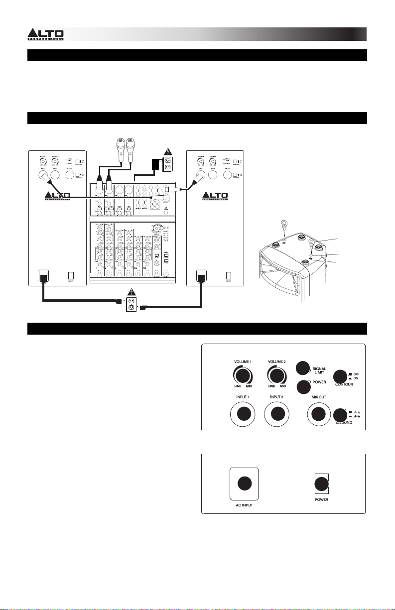
CONNECTION DIAGRAM / INSTALLATION
Speaker
Note: Microphones, mixer,
and cables are not included.
Microphones*
Power
Power
Mixer*
Speaker
INSTALLATION:
This speaker should be installed on a
stand on the floor, according to its
maximum weight, or suspended from its
suspension points (M10 x 1.5PH, 30mm
length) (see example image). We do
NOT recommend suspending multiple
speakers in a vertical array.
Example:
Eyebolt
Dust cover
Suspension
point
REAR PANEL OVERVIEW
1. POWER INPUT – Connect the included power
cable to this input and connect the other end of
the cable to a power source. Make sure the
speaker's POWER SWITCH is set to "off"
when plugging and unplugging the cable.
2. POWER SWITCH – Turns the speaker on/off.
Make sure the VOLUME knob is set to "zero"
before turning it on.
3. POWER LED – Illuminates when the speaker
is on.
4. VOLUME – Turn this knob to adjust the
speaker's volume.
5. INPUT – Use a standard 1/4" TRS or XLR
cable (not included) to connect your sound
source to this input.
6. MIX OUT – Use a standard XLR cable (not
included) to connect this jack to the input of
another speaker (i.e., another TRUESONIC
speaker).
7. SIGNAL LIMIT LED – Illuminates when the
audio signal being sent to the speaker is
"clipping" or distorting. If this light illuminates
frequently or steadily, reduce the volume of your sound source.
8. CONTOUR – Engage (depress) this switch to equalize the mix for optimal music playback. Disengage
(raise) the switch during live performance for a flatter response.
9. GROUND SWITCH – Press this switch to reduce hum or noise.
44
55
1
7
8
3
6
9
2
2
Page 3
*
CONTENIDO DE LA CAJA
• Altavoz TRUESONIC
• Cable de alimentación
• Guía de inicio rápido
• Folleto de instrucciones de seguridad e información sobre la garantía
DIAGRAMA DE CONEXIÓN / INSTALACIÓN
Altavoz
Nota: No se incluyen micrófonos,
mezclador y cable.
VISTA DEL PANEL TRASERO
1. ENTRADA DE ALIMENTACIÓN – Conecte a
esta entrada el cable de alimentación incluido
y luego conecte el otro extremo del cable al
suministro eléctrico. Asegúrese de que el
INTERRUPTOR DE ENCENDIDO esté en "off"
(apagado) cuando enchufe y desenchufe el
cable.
2. INTERRUPTOR DE ENCENDIDO – Enciende
y apaga el altavoz. Asegúrese de que la perilla
de VOLUMEN esté ajustada a "cero" antes de
encenderlo.
3. LED DE ENCENDIDO – Se ilumina cuando el
altavoz está encendido.
4. VOLUMEN – Gire esta perilla para ajustar el
volumen del altavoz.
5. ENTRADA – Use un cable de 1/4" TRS o XLR
estándar (no incluido) para conectar su fuente
de sonido a esta entrada.
6. SALIDA DE MEZCLA – Use un cable XLR
estándar (no incluido) para conectar este
conector a la entrada de otro altavoz (por ej.
otro altavoz TRUESONIC).
7. LED DE LÍMITE DE SEÑAL – Se enciende cuando la señal de audio que se envía al altavoz se
"recorta" o distorsiona. Si esta luz se enciende con frecuencia o en forma permanente, reduzca el
volumen de su fuente de sonido.
8. CONTORNO – Accione (presione) este interruptor para enfatizar las frecuencias bajas y altas en +3
dB. Libere este interruptor para lograr una respuesta más plana en interpretaciones en vivo o para
máxima salida.
9. INTERRUPTOR DE TIERRA – Pulse este interruptor para reducir el zumbido o ruido.
Micrófonos *
Potencia
Potencia
Mezclador *
Altavoz
INSTALACIÓN:
Este altavoz debe instalarse sobre un
soporte colocado en el suelo, de acuerdo
a su peso máximo, o suspendido de sus
puntos de suspensión (M10 x 1.5PH, 30
mm de longitud) (vea la imagen de
ejemplo). NO recomendamos suspender
varios altavoces en un arreglo vertical.
Ejemplo:
44
7
3
55
1
6
2
Perno de
ojal
Cubierta
antipolvo
Punto de
suspensión
8
9
3
Page 4

*
e
CONTENU DE LA BOÎTE
• Haut-parleur TRUESONIC
• Câble d'alimentation
• Guide d’utilisation simplifié
• Consignes de sécurité et informations concernant la garantie
SCHÉMA DE CONNEXION / INSTALLATION
Haut-parleur
Remarqu
console de mixage, non inclus.
Microphones*
Alimentation électrique
: Microphones, câbles,
Alimentation électrique
Console de
mixage *
Haut-parleur
INSTALLATION:
Ce haut-parleur doit être installé sur un
pied sur le plancher, en fonction de son
poids maximum, ou suspendu par ses
points d’ancrage (M10 x 1,5 PH, 30 mm de
longueur) (Consultez l’image). Nous NE
RECOMMANDONS PAS de suspendre
plusieurs haut-parleurs ensemble.
Exemple :
Boulon à
œil
Housse de
protection
Point
d’ancrage
CARACTÉRISTIQUES DU PANNEAU ARRIÈRE
1. ENTRÉE D’ALIMENTATION – Branchez le
câble d’alimentation inclus à cette entrée et
branchez l’autre extrémité à une source
d’alimentation électrique. Assurez-vous que
l’interrupteur de mise en marche est réglé sur
« Off » lorsque vous branchez/débranchez le
câble d’alimentation.
2. INTERRUPTEUR D'ALIMENTATION – Met
l’appareil sous et hors tension. Assurez-vous
que le bouton du volume soit complètement
fermé (« zéro ») avant de mettre le hautparleur sous tension.
3. DEL D’ALIMENTATION – S’allume lorsque le
haut-parleur est sous tension.
4. VOLUME – Ce bouton permet d’ajuster le
volume des haut-parleurs.
5. ENTRÉE – Utilisez un câble TRS ou XLR de
¼ po (non inclus) pour brancher une source
audio à cette entrée.
6. SORTIE MIXAGE – Utilisez un câble XLR
standard (non inclus) pour brancher cette
sortie à l’entrée d'un autre haut-parleur, tel
qu’un autre haut-parleur TRUESONIC.
7. DEL D'ÉCRÊTEMENT – S’allume pour indiquer l’écrêtement du signal. Si la DEL clignote ou s’allume
de façon constante, diminuez le volume de la source audio.
8. CONTOUR – Lorsque cette touche est enfoncée, les basses et hautes fréquences sont accentuées de
+3 dB. Désactivez pour un son plus plat pour les prestations ou pour optimiser la puissance de sortie.
9. INTERRUPTEUR DE MISE À LA TERRE – Appuyez sur cet interrupteur pour réduire les bruits
indésirables.
44
55
1
7
8
3
6
9
2
4
Page 5

*
CONTENUTI DELLA CONFEZIONE
• Altoparlante TRUESONIC
• Cavo di alimentazione
• Guida rapida
• Istruzioni di sicurezza e garanzia
SCHEMA DEI COLLEGAMENTI / INSTALLAZIONE
Altoparlante
Nota bene: microfoni, mixer,
altoparlanti e cavi non in dotazione.
Microfoni *
Alimentazione
Alimentazione
Mixer*
Altoparlante
INSTALLAZIONE:
Questo altoparlante deve essere
installato su un supporto da pavimento,
in base al suo peso massimo, oppure
appeso servendosi degli appositi punti di
sospensione (M10 x 1,5PH, 30 mm di
lunghezza) (si veda l'immagine di
esempio). NON si consiglia di
sospendere più altoparlanti in verticale.
Esempio:
Bullone a
occhiello
Coperchio
antipolvere
Punto di
sospensione
PANORAMICA PANNELLO POSTERIORE
1. INGRESSO DI ALIMENTAZIONE – Collegare
il cavo di alimentazione in dotazione a questo
ingresso, quindi collegare l’altro capo del cavo
stesso ad una sorgente di alimentazione.
Assicurarsi che l'INTERRUTTORE DI
ALIMENTAZIONE dell'altoparlante sia su "off"
al momento di collegare e scollegare il cavo.
2. INTERRUTTORE DI ALIMENTAZIONE
(POWER) – Accende e spegne l'altoparlante.
Assicurarsi che la manopola VOLUME sia
impostata su "zero" prima di accenderlo.
3. LED DI ALIMENTAZIONE – Si illumina
quando l'altoparlante è acceso.
4. VOLUME – Girare questa manopola per
regolare il volume dell'altoparlante.
5. INGRESSO – Servirsi di un cavo standard
TRS o XLR da 1/4" (non in dotazione) per
collegare la fonte audio a questo ingresso.
6. USCITA MIX – Servirsi di un cavo standard
XLR (non in dotazione) per collegare questo
jack all'ingresso di un altro altoparlante (ad es.
un altro altoparlante TRUESONIC).
7. LED LIMITE DI SEGNALE – Si accende quando il segnale audio inviato all'altoparlante "salta" o viene
distorto. Se questa spia si accende spesso o in maniera fissa, ridurre il volume della fonte audio.
8. CONTOUR – Premere questo interruttore per enfatizzare frequenze alte e basse di +3 dB. Disattivare
l'interruttore per una risposta più blanda per prestazioni dal vivo o per il massimo dell'uscita.
9. INTERRUTTORE DI MESSA A TERRA – Premere questo interruttore per ridurre il ronzio o rumore.
44
55
1
7
8
3
6
9
2
5
Page 6

*
r
LIEFERUMFANG
• TRUESONIC Lautsprecher
• Netzkabel
• Kurzanleitung
• Sicherheitshinweise und Garantieinformationen
ANSCHLUSSÜBERSICHT / MONTAGE
Lautsprecher
Hinweis: Mikrofone, Mixer und Kabel sind nicht im Lieferumfang enthalten.
Mikrofone *
Stromversorgung
Stromversorgung
Mixer*
Lautsprecher
MONTAGE:
Dieser Lautsprecher sollte seinem
Maximalgewicht entsprechend auf einem
Bodenstativ montiert oder an den
Aufhängepunkten aufgehängt werden
(M10 x 1.5PH, 30mm Länge) (siehe
Beispielbild). Mehrere Lautspreche
vertikal aufzuhängen ist NICHT
empfehlenswert.
Beispiel:
Ringschraube
Staubabdeckung
Aufhängepunkt
ÜBERSICHT RÜCKSEITE
1. NETZEINGANG – Verbinden Sie das mitgelieferte
Netzkabel mit diesem Eingang und das andere
Ende des Kabels mit einer Stromquelle. Achten
Sie darauf, dass der NETZSCHALTER des
Lautsprechers auf "off" steht, wenn Sie das Kabel
anschließen oder abstecken.
2. NETZSCHALTER – Schaltet den Lautsprecher
ein/aus. Achten Sie darauf, dass der
LAUTSTÄRKE-Regler auf "Null" steht, bevor Sie
den Lautsprecher einschalten.
3. POWER-LED – Leuchtet, wenn der Lautsprecher
eingeschaltet ist.
4. LAUTSTÄRKE – Drehen Sie diesen Knopf, um die
Lautstärke des Lautsprechers einzustellen.
5. EINGANG – Verwenden Sie ein handelsübliches
1/4"-Klinken- oder XLR-Kabel (nicht im
Lieferumfang enthalten), um Ihre Tonquelle mit
diesem Eingang zu verbinden.
6. MIX-AUSGANG – Verwenden Sie ein
handelsübliches XLR-Kabel (nicht im Lieferumfang
enthalten), um diese Buchse mit dem Eingang eines anderen Lautsprechers (d.h. eines weiteren
TRUESONIC Lautsprechers) zu verbinden.
7. LIMIT-LED – Leuchtet auf, wenn das an den Lautsprecher gesendete Audiosignal "clippt" oder
verzerrt. Sollte diese LED häufig oder ständig leuchten, reduzieren Sie die Lautstärke Ihrer Tonquelle.
8. KONTUR – Aktivieren (drücken) Sie diesen Schalter, um niedrige und hohe Frequenzen um +3 dB zu
verstärken. Lösen Sie den Schalter für maximale Leistung oder ein flacheres Ansprechverhalten bei
Live-Auftritten.
9. ERDUNGSSCHALTER – Drücken Sie diesen Schalter, um Brummgeräusche oder Rauschen zu
reduzieren.
44
55
1
7
8
3
6
9
2
6
Page 7

INHOUD VAN DE DOOS
• TRUESONIC luidspreker
• Stroomkabel
• Snelstartgids
• Veiligheidsvoorschriften & boekje met informatie over de garantie
VERBINDINGSDIAGRAM / INSTALLATIE
Luidspreker
*Opmerking: Microfoons, mengpaneel en kabels zijn niet inbegrepen.
Microfoons*
Stroom
Stroom
Mengpaneel*
Luidspreker
INSTALLATIE:
Deze luidspreker dient te worden
geplaatst op een vloerstatief aangepast
aan het maximumgewicht, of opgehangen
aan zijn ophangpunten (M10 x 1.5PH, 30
mm lengte) (zie afbeelding als voorbeeld).
Wij raden u NIET aan meerdere
luidsprekers in een verticale opstelling op
te hangen.
Voorbeeld:
Oogbout
Stofkap
Ophangpunt
OVERZICHT ACHTERPANEEL
1. POWER INPUT – Sluit de meegeleverde
stroomkabel aan op deze ingang en sluit het
andere uiteinde van de kabel aan op een
stroombron. Zorg ervoor dat de POWERschakelaar van de luidspreker op "off" staat bij
het aansluiten en loskoppelen van de kabel.
2. POWER SWITCH – Schakelt de luidspreker
aan/uit. Zorg ervoor dat de VOLUME-knop op
"nul" staat voor het inschakelen.
3. POWER LED – Brandt wanneer de luidspreker
is ingeschakeld.
4. VOLUME – Draai deze knop om het
luidsprekervolume aan te passen.
5. INPUT – Gebruik een standaard 1/4" TRS- of
XLR-kabel (niet meegeleverd) om uw
geluidsbron op deze ingang aan te sluiten.
6. MIX OUT – Gebruik een standaard XLR-kabel
(niet meegeleverd) om deze aansluiting te
verbinden met de ingang van een andere
luidspreker (bijv. een andere TRUESONICluidspreker).
7. SIGNAL LIMIT LED – Gaat branden wanneer
het audiosignaal, verzonden naar de luidspreker, begint te "clippen" of vervormd is. Als dit lampje vaak
of gestaag brandt, verlaag dan het volume van uw geluidsbron.
8. CONTOUR – Deze schakelaar activeren (indrukken) om lage en hoge frequenties met +3 dB te
versterken. De schakelaar uitzetten voor een vlakkere respons tijdens live uitvoeringen of voor een
maximale output.
9. GROUND SWITCH – Druk op deze schakelaar om brom of ruis te verminderen.
44
55
1
7
8
3
6
9
2
7
Page 8

SPECIFICATIONS
Output Power: 300 W Continuous RMS (235 W LF + 65 W HF)
Active Crossover: 2.5 KHz
Max SPL @ 1m: 120 dB Continuous, 123 dB Peak
Frequency Range: 53 Hz – 20 kHz (@ -10 dB)
Frequency Response: 70 Hz – 19 kHz (+
Max Input Level: +18 dBu (input impedance: 15 kΩ)
Transducer Low: 10" (254 mm) woofer, 2" (51 mm) voice coil
Transducer High: 1" (25mm) exit with 1" (25 mm) neodymium compression driver
Horn Coverage: 80/100° H x 60° V nominal
Connectors: Mic/Line Input: two 1/4" TRS or XLR
Cabinet: Trapezoidal, with floor monitor capability. Injection molded, polypropylene
External Control: Volume, power on/off with LED, clip limiter with LED, ground lift
Protection: Over-excursion, thermal, driver
Power supply: 100-120 V or 200-240 V, 50/60 Hz
Inrush current at initial switch-on: 4.36 A
Mounting: Integrated pole-socket (36 mm dia.), one handle, four M10-threaded
Dimensions (H x W x D): 20.2" x 13" x 11.7" (513 mm x 330 mm x 297 mm)
Weight (speaker only): 26.6 lbs (12.1 kg)
THIS DEVICE COMPLIES WITH PART 15 OF THE FCC RULES. OPERATION IS SUBJECT TO THE
FOLLOWING TWO CONDITIONS: (1) THIS DEVICE MAY NOT CAUSE HARMFUL INTERFERENCE, AND (2)
THIS DEVICE MUST ACCEPT ANY INTERFERENCE RECEIVED, INCLUDING INTERFERENCE THAT MAY
CAUSE UNDESIRED OPERATION.
600 W Peak (470 W LF + 130 W HF)
3 dB)
Link Output: one XLR
enclosure, with perforated steel grille
Inrush current after power supply interruption: 3.73 A
sockets (2 top, 2 bottom)
www.altoprofessional.com
MANUAL VERSION 1.1
 Loading...