

Page 1

Service Manual
ELVIS ACTIVE SPEAKER CABINET
MODEL: ELVIS10A/ELVIS12A/ELVIS15A/
ELVIS12MA/ELVIS12SA/ELVIS15SA
LTO
www.altoproaudio.com
Version 1.0
R
Page 2

CONTENTS
1
1. Warning
2. Technical Specification & Transistor Packages
3. Test Procedure & Setting
4. Schematic Diagram
5. Spare Part List
............................................................................................................................................................... 2
............................................................................................................................... 4-6
....................................................................................................................................... 7-17
.................................................................................................................................................. 18
............................................................................................ 3
Page 3

1. Warnning
2
Service must be carried out by ALTO qualified personnel only.
Unqualified service personnel used in the warranty time of the product, produce a falling of the warranty.
Schematic diagram and part list of the devices may be subject to change without immediate notice.
When to replace any components, use only original spare parts.
All the resistors are at 1/8 Watt, all the electrolytic capacitors are at 25V, unless otherwise specified.
The symbol used for the resistors are R (ohm) and for the capacitors are U (microfarad).
Page 4
2. Technical Specification & Thansistor Packages
3
ELVIS10A ELVIS12A ELVIS15A ELVIS12MA
Output Power IHF
Output Power RMS
Max SPL at 1mt
Input Sensitivity
Input Impedance
Connectors
Subsonic Filter
Protections
External Control
Power Supply
Net Weight lbs/kg
Gross Weight lbs/kg
Shipping Volume
Output Power IHF
Output Power RMS
Max SPL at 1mt
Input Sensitivity
Input Impedance
Connectors
Subsonic Filter
Protections
External Control
Power Supply
Net Weight lbs/kg
Gross Weight lbs/kg
Shipping Volume
150Watt IHF 250Watt IHF 350Watt IHF 250Watt IHF
120Watt RMS 180Watt RMS 250Watt RMS 180Watt RMS
117.5 dB ( IHF Power ) 121 dB ( IHF Power ) 123 dB ( IHF Power ) 121 dB ( IHF Power )
Line 0dB/0.775V/Mic-10 at -45dB
30kOhms Balanced - 15kOhms Unbalanced
Mic on XLR/Line Input on Combo/Line-Mix Output on XLR
30Hz - 24dB/oct. 30Hz - 24dB/oct. 30Hz - 24dB/oct. 30Hz - 24dB/oct.
Soft - Start DC voltage protect - compressor
Mic Gain - EQ-High-Mid-Low-Volume-Ground Switch
40.12lbs/18.2kg
46.83lbs/21.24kg
4.58CFT
121 dB ( IHF Power ) 123 dB ( IHF Power )
60.36lbs/27.38kg
67.19lbs/30.48kg
6.15CFT
50.95lbs/23.11kg
58.89lbs/26.71kg
6.03CFT
ELVIS12SA ELVIS15SA
250Watt IHF 350Watt IHF
180Watt RMS 250Watt RMS
Line 0dB/0.775V
30kohms-input/600ohms-output
L/Mono-R IN on XLR/L-R OUT on XLR
Electronic Crossover 125Hz at 24dB/oct.
Soft start-DC voltage protect -compressor
Volume - Stereo/Mono & Ground Swicth
230Volt/115Volt 50/60Hz
230Volt/115Volt 50 / 60Hz
62.83lbs/28.5kg
71.52lbs/32.44kg
7.35CFT
49.54lbs/22.47kg
56.92lbs/25.82kg
6.10CFT
76.68lbs/34.78kg
85.72lbs/38.88kg
8.67CFT
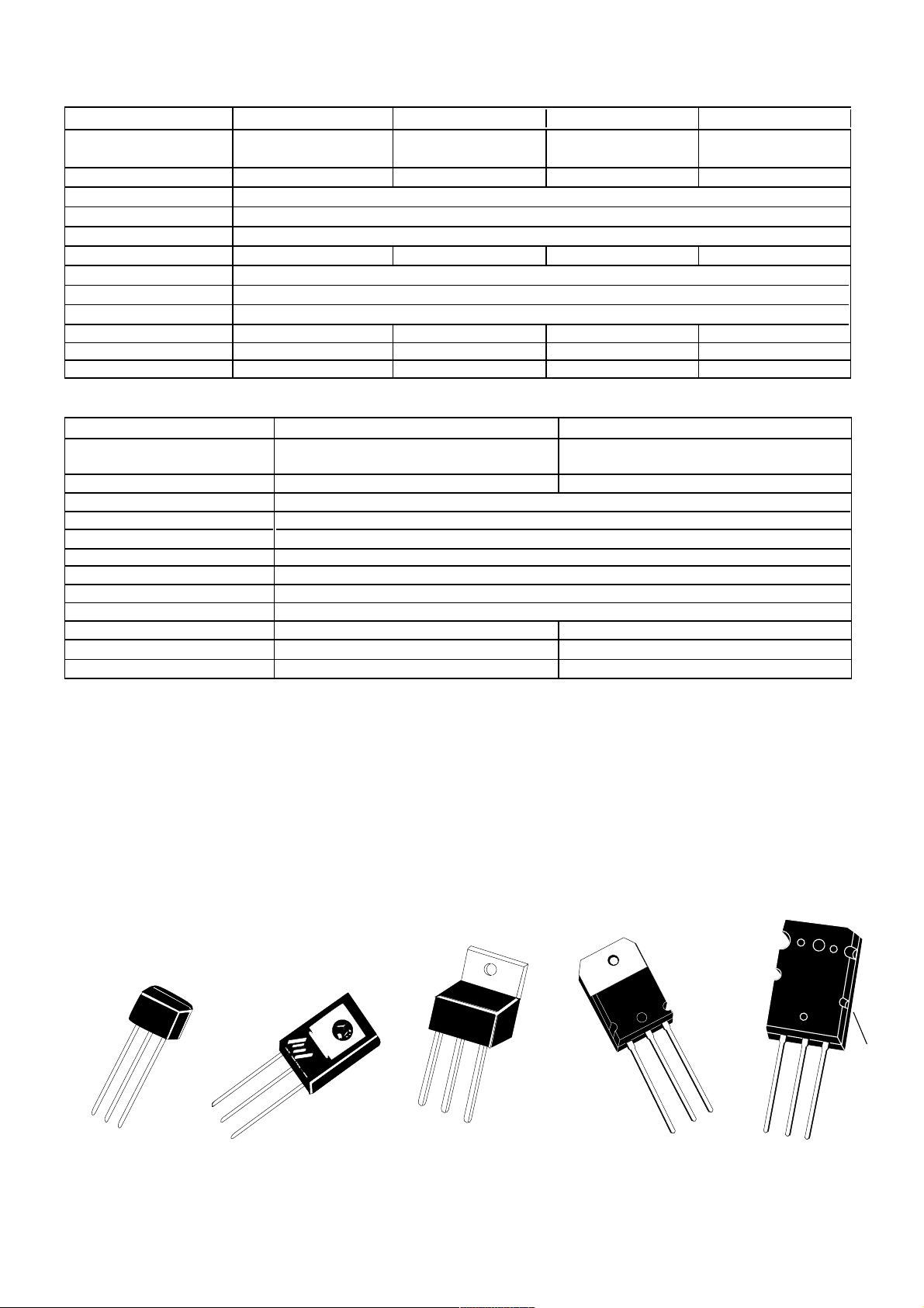
Transistor Packages
TO92
2SC1815, 2SA1015:
1=Emitter
2=Collector
3=Base
2N5401, 2N5551:
1=Emitter
2=Base
3=Collector
1
2
3
3
2
TO126
MJE340, MJE350,
MJE802:
1=Emitter
2=Collector
3=Base
4=Collector
1
TO220
MJE15030, MJE15031:
1=Base
2=Collector
3=Emitter
4=Collector
4
TO218
TIP35C, TIP36C:
1=Base
2=Collector
3=Emitter
4=Collector
4
4
1
2
3
2
1
TO264
2SC5200, 2SA1943:
1=Base
2=Collector
3=Emitter
4=Collector
3
1
4
2
3
Page 5

3. Test procedures & Setting
4
CAUTION
Before removing or installing the Power amplifier, switch off and disconnect the power cord from the AC mains socket. When you have visible
the components, discharge the capacitor before to start the maintenance.
When you connect the probe to the output of amplifier, insulated the earth of the oscilloscope, to prevent short circuit during the test.
The Power Amplifier work in Class H and use a dual bipolar rail configuration, one low rail(+/-Vcc1)RMS power and second high rail (+/-Vcc2)
IHF power.
Read the Service Manual before to proceeding to any operation.
VISUAL INSPECTION
Before to proceed with maintenance, look the condition of the product, for define the entity of the damage and probably cause.
Disconnect the power amplifier from the cabinet and look if appears an evident mechanical damage or an assembled circuit burn or break.
Verify the integrity of acoustical component, disconnect from the passive crossover and measure with a digital multi-meter the resistor of the
voice coil of the woofer Rcc=3.5/6 ohm and of the driver Rcc=6 ohm. If you measure a resistor with less value the voice coil is in short circuit,
if you measure open circuit the voice coil is break off.
OPTIMUM TEST INSTRUMENT
FUNCTION GENERATOR
DUAL-CHANNEL OSCILLOSCOPE
DIGITAL MULTIMETER
FAN LOAD RESISTORS 4 OHM/400W
VARIAC(0-250VAC)
POWER MODULE SETUP
Remove the transformer with your bracket, unscrew the 8 screw M4 without remove the electrical connection.
Fix the heat sink with PCB amplifier on the chassis with 2 screw, for prevent casual damage.
Turn full anticlockwise the knob of Main Volume, for prevent the signal noise at the Input of the amplifier.
Connect the digital multi-meter set in Vcc, across the R33=0.22R 5W, if you have a analog tester set at a correct scale and respect the polarity.
Set the trimmer VR1 used for the idle current, in full anticlockwise position, for prevent the damage of the amplifier, during the setting.
Set the VARICAL at 0VAC and connect from the 230VAC mains socket an the power amplifier under test, verify that the socket and the power
cord included the earth ground connected.
ADJUSTMENT
Switch ON the power amplifier and increase slowly with the Variac, the AC voltage until 230V.
See on the digital multi meter and read a value near to 0 mV(Vcc), turn in clockwise the trimmer VR1 until to read 5mV(+/-0.5mV) across the
R33, now wait until the temperature rise, in the same time also the voltage rise, turn in anticlockwise the trimmer VR1 until to read again
5mV(+/-0.5mV) across R33, read the same value also on R34 (+/-1mV) and verify the stability of the value, do not risk a thermal drift, repeat
the setting procedure.
When you are sure of the stability of power module, switch OFF the power amplifier disconnect the multi meter, assemble the transformer
with bracket on the chassis with at the 8 screw M4.
Page 6

MAIN SETUP
5
Connect the VARIAC set at 0VAC from the Mains AC voltage and the power amplifier under test and use a power cord with ground connected.
Turn full anticlockwise the knob of Main Volume.
Set the EQ filter, Low-Mid-High in central position.
Connect the Function Generator to the Line Input(Combo) and set at 1kHz/0.775V.
Connect the Oscilloscope with CH1 probe linked to the Input of the Function Generator and the CH2 probe to the Output of the power amplifier.
Connect a 4 ohm/400W fan load Resistors with an ON/OFF switch and start in OFF position.
DC OFFSET
Switch On the Power Amplifier under test, increase with the VARIAC the AC Voltage slowly and verify in the CH2 the offset stability, reduce
the sensitivity from 20V/div at 5V/div and confirm a maximum offset at +/-0.5VDC.
Switch ON the 4 ohm resistive Load and verify same conditions.
FREQUENCY RESPONSE
Open slowly the Main Volume and verify a perfect 1kHz sinusoidal wave, increase the level until to see a symmetrical square wave.
EQ FILTER
Set the Function Generator at 10dB (0.245V) and test the EQ control.
LOW-EQ control at 100Hz with a range of +/-6dB, Max./Min. of the knob.
MID-EQ control at 2kHz with a range of +/-6dB, Max./Min. of the knob.
HIGN-EQ control at 10kHz with a range of +/-6dB, Max./Min. of the knob.
MIC GAIN
Set the Function Generator at 10dB(0.245V), connect to MIC input and control the frequency response.
SIG/COMP
Set the knob of the Main Volume at 1/4, set the CH2 at 5V/div, increase the level at 1kHz and check the SIG/COMP LED colour, when the
output is 5V the colour is green. Set the CH2 at 20V/div and increase the level, it must be change from green to red colour, if you increase the
input , the output level must keep at same level.
GROUND LIFT
Check the ground-lift with a digital multi-meter, the switch remove the electrical ground Of the input connector (Combo and XLR) form the earth
ground of the chassis.
Page 7

ELVIS 10
SUPPLY TEST
6
TRANSFORMER-Primary 230VAC/50Hz; ... VA-... A
Secondary low rail ...V-0-...VAC; high rail ...V-0-...VAC
DC SUPPLIES: +VDC2 on Q5 - TIP36C-emitter pin3 value+......V
+VDC1 on D9 - UF50 anodo value+......V
U7 pin3 value+15V
U6 pin3 value -15V
- VDC1 on D8 - UF50 anodo value -......V
- VDC2 on Q7 -TIP35C-emitter pin3 value -......V
ELVIS 12
TRANSFORMER-Primary 230VAC/50Hz; 210 VA-4.7A
Secondary low rail 20V-0-20VAC; high rail 38V-0-38VAC
DC SUPPLIES: +VDC2 on Q5 - TIP36C-emitter pin3 value+58V
+VDC1 on D9 - UF50 anodo value+30V
U7 pin3 value+15V
U6 pin3 value -15V
- VDC1 on D8 - UF50 anodo value -30V
- VDC2 on Q7 -TIP35C-emitter pin3 value -58V
ELVIS 15
TRANSFORMER-Primary 230VAC/50Hz; ... VA-...A
Secondary low rail ...V-0-...VAC; high rail ...V-0-...VAC
DC SUPPLIES: +VDC2 on Q5 - TIP36C-emitter pin3 value+......V
+VDC1 on D9 - UF50 anodo value+......V
U7 pin3 value+15V
U6 pin3 value -15V
- VDC1 on D8 - UF50 anodo value -......V
- VDC2 on Q7 -TIP35C-emitter pin3 value -......V
Page 8

4. Circuit Board & Schematic Diagram
P-Elvis-Xover
Botton layer
Top layer
7
Page 9

P-Elvis-PRE
Botton layer
Top silkscreen overlay
8
Page 10

Top layer
9
Page 11

P-Elvis-AMP
Botton layer
Top layer
10
Page 12

Top silkscreen overlay
11
Page 13

ELVIS PRE 150W
12
1
4K7
R46
GND
15K
Z1
Z2
1
J1
2
1
1
C8
2n2F
2
C7
4K7
1
2
COMBOJACK
B
C28
2
POT-DARL
8
1
2
1
R29
2
2
R48
1
B
6
_
B
E
B
Q6
2
C
R55
330R
1
100nF
C1
10K
10
R37
4K7
2
+
U1-C
TL074AC
1K2
R30
1K2
1
2
3
1
J3
XLR-3P-TIPC1
E
Q5
2
C
10pF
C42
C
R51
330R
1
Q4
E
2
R18
1
1
R19
10K
1
2
3
1
10nF
R20
2
GND
C15
22pF
R28
15K
1
Z4
Z3
2
R3
1
10nF
C9
R13
10E 1/2W
2
1
B
2
R15
2K7
VR3
POT-DARL
2K7
10K
10K
1
1
2
3n3F
C2
VR2
2
3
2
R16
12K
R17
10K
1
1
2
R39
2
9
1
_
10pF
R42
10K
C32
1
C10
S2
FASTON1
1
2
2
1
S1
1
22pF
Z5Z6Z7
330R
C
C41
C14
2
R34
10K
1
134
D3
2
B
Q2
E
C
7
2
_
22pF
C26
R41
10K
1
C23
220nF
2
R36
4K7
1
1
+_U2-A
TL072
2
3
2
C16
22pF
R25
2K2
R31
1K
2
1
Z8
C
6
1
2
R56
22K
2
R57
330R
OUT(1)
1
10uF
C40
1
+_U4-A
TL072
2
3
7
2
+
U4-B
_
10pF
2
10pF
2
22pF
C30
R12
2
C3
+
U1-B
TL074AC
5
TL072
R50
33K
1
R38
4K7
2
1
+_U1-A
3
R44
330R
10uF
C17
R35
TL074AC
2
1
1
3
22pF
R58
1
2
6
5
R52
22K
1
C45
10uF
7
+
U3-B
_
TL072
R45
15K
2
6
5
470nF
C31
1
470nF
C19
1
+_U3-A
TL072
R40
15K
2
2
3
470nF
C12
4K7
1
470nF
C13
2
R14
330R
2
1
R21
4K7
1
1
2
VR4
POT-DARL
3
2
R22
4K7
1
10uF
C6
7
+
_
22K
TL072
U2-B
6
5
2
2
R1
22K
1
2
POT-DARL
VR5
1
1
R26
4K7
2
2
14
OP-14P
R32
15K
+
_
U1-D
1
13
12
2
2
R27
R33
15K
1
1
C5
22pF
2
2
R2
R4
330R
330R
1
1
3
2
456
D
MUTE(1)
OUT(1)
J5-4
J5-5
1
AMPMODU1-8
J5-3
5
J4-E
TEP(1)
J5-1
J5-2
2
AMPMODU1-8
J4-B
D
D5
+15V
+VCC1
2
F1
4A
1
1
2
S7
AMPMODU1-8
J4-C
+VCC2
3
Out
In
U7
2
R61
68R
FASTON1
3
AMPMODU1-8
GND
2
F4
1
2
S3
6
J4-F
LM7815CT
1
C24
4700uF50V
3
D2
C46
10uF
C49
100nF
1
C52
100nF
C53
22uF63V
C29
4700uF50V
3
D4
2A
FASTON1
+15V
7
AMPMODU1-8
J4-G
1
2
RCT-KBP
C47
0.047uF-250AC
1
RCT2
2
C27
0.047uF-250AC
1
2
FASTON1
S5
C44
R60
2
MUTE(1)
8
AMPMODU1-8
J4-H
C50
4700uF50V
4
-15V
C36
10uF
C39
100nF
1
C43
100nF
C37
22uF63V
C51
4700uF50V
4
2
F3
1
1
2
S4
2
100nF
R49
1
2
R59
1
10K
1
TEMP(1)
R10
AMPMODU1-8
D6
-VCC2
3
Out
GND
In
U6
LM7915CT
2
R43
68R
-VCC1
2
F2
2A
1
1
2
FASTON1
S6
2
R47
10K
1
1
TL072
+_U5-A
10K
2
3
2
R53
10K
10K
1
CLIP(1)
VR1
POT-DARL
3
2
2
2
R11
330R
15K
1
1
C11
22pF
2
2
R23
R24
330R
1
1
3
1
2
J2
XLR-3P-F-TUPO1
4A
FASTON1
C25
8
7
6
5
4
3
CLIP(1)
J5-6
2
-15V
+15V
-VCC1
+VCC1
-VCC2
4
+VCC2
1
AMPMODU1-8
J4-A
J4-D
A
Revision
8
Sheetof
By:
150W
Number
R
24-Dec-2004
C:\DocumentsandSettings\PC98.PC98\®à ±\1.DDBDrawn
PE
A2
Date:
Size
Title
File:
100nF
100nF
100nF
100nF
2
R7
1
7
6
5
-15V
-15V
-15V
4
-15V
-15V
3
2
2
R9
2K7
2K7
1
1
K
2
LEDP
D1
A
10uF
10K
5
+
U5-B
TL072
7
2
R54
10K
1
D7
1N4148
C34
C20
100nF
+15V
C18
C33
100nF
+15V
C21
C22
100nF
+15V
C38
C48
100nF
+15V
C54
C55
100nF
100nF
+15V
1
-15V
C35
100nF
C4
1uF
Q1
E
C
R5
10K
B
1
2
2
2
R8
R6
10K
1K
1
1
B
C
LEDBIC
3
Q3
E
1
DL1
A
Page 14

ELVIS AMP 150W
13
D14
R3
390R
R18
1K
1N4002
47uF100V
C16
A
Revision
8
By:
Sheetof
W
50
1
M
AP
Number
C:\DocumentsandSettings\PC98.PC98\®à ±\1.DDB Drawn
24-Dec-2004
A2
File:
Date:
Size
Title
7
6
C6
100nF-100V
E
1
1
5
4
3
2
1
Q12
B
1
2
R22
1
FASTON 1
FE68
100nF
C23
1N4148
1
47K
BC550
E
1
2
R35
1
2
R39
1
B
E
C13
1uF
D10
C10
8K2
1N4002
R37
R38
1N4002
C
2
R10
1
D1
2
68R
820R
Q4
4n7F
47R
C
TIP41C
C3
1N4002
R6
R2
1
1
470pF
12K
8K2-2W
Q7
-VCC2
TIP35C
B
2
2
1
-VCC1
C14
D8
100nF-100V
10K
+
U1-A
TIP42C
B
2
R56
1
E
2
R43
1
3
1K
1
C
1
4R7
12K
2
TL072
1N4148
D22
Q22
1N4002
C
MJE350
B
R44
+15V
VF60
Q2
MJE350
E
R8
2K2
1
2
B
R9
47K
1
2
C
220pF
C21
C
C22
100pF
B
1N4148
D16
88K
1
R46
4K7
2
R45
12K
2
2
R11
1
D2
C5
4n7F-400V
R12
8K2
1
2
C1
220uF
Z1
7V5
Q16
MJE340
2
E
2
B
C
Q17
2N5401
E
1
1
R28
10R-2W
2
Q13
TIP36C
B
Q23
10R
E
R42
470R
2
D20
1N4002
470R
2
R47
1
2
2
_
22pF
R48
10K
1
1
D19
2
R65
1
CLIP(1)
2
2
2
+VCC1
2K2
R15 47K
B
C
E
C
K1-C
1
2
D6
1N4002
100nF
C
R25
10K
1N4002
C
E
1K5
1
C12
R21
150R
1
2
Q11
BC560
1
E
C
B
R26
330R
1
2
R19
33K
2
E
Q6
BC560
E
B
R20
10K
1
C
BC550
Q9
E
Q8
BC550
E
100uF
B
C15
R29
4K7
2
1
2
R32
47K
1
Q15
TIP35C
C
E
2
B
Q21
R36
TIP41C
10R
E
1
R55
470R
1
2
B
D23
1N4002
2
R54
4R7
1
2
R53
12K
1
C31
10uF
Q24
MJE802
E
3
2
VR1
470R
B
1
R57
560R
1
2
2
7
R59
1K
_
U1-B
+
1
4n7F
6
5
C28
2
2
R61
1K
1
10uF
C20
INPUT(1)
-15V
C
C
R24
150K
2
+15V
B
MUTE(1)
FASTON 1
S2
S1
1
2
1
2
4
5
7
8
K1-A
K1-B
3
6
R34
R33
OR22
OR22
1
2
2
D13
FE68
D22
TL072
2
R60
1K
1N4002
R58
D12
D21
1N4002
C18
2
R49
100K
1
1K
1
1
2
D18
R64
2K7
1
10uF
C27
Q10
BC560
E
R23
10K
1
2
B
R32
10K
1
2
C11
220uF
Q14
BC560
C
R31
10K
1
2
B
2
R27
10K
1
2
C
VF60
D9
D11
1
1
Q20
MJE340
C
B
220pF
C26
1
C
C
2
1nF
C30
C25
100pF
R63
1
B
D17
1N4148
R52
68K
2
R50
4K7
1
R51
12K
1
-15V
D
8
7
6
C8
100nF-100V
D7
1N4002
Q5
TIP36C
E
2
2
6
J1-F
B
R5
390R
E
R4
1K
3
AMPMODU1-8
J1-C
C
Q1
TIP42C
1
B
1
R7
2
R2
D15
1N4002
2
AMPMODU1-8
J1-B
C
C10
C
C4
470pF
2
R14
1
D41N4002
12K
1
8K2-2W
2
2
MUTE(1)
1
AMPMODU1-8
J1-A
4n7F
Q3
B
2
2
R13
8K2
47R
1
D3
1N4002
2
R40
68R
R41
820R
47uF100V
C17
AMPMODU1-8
MJE340
Z2
1
1
E
2
R17
C2
7V5
E
R16
C7
4n7F-400V
8K2
220uF
Q19
Q18
5
4
3
2
R62
INPUT(1)
J2-3
J2-4
J2-2
8
AMPMODU1-8
AMPMODU1-8
J1-H
1
J2-5
4
J1-D
PTC100
65432
J2-6
7
AMPMODU1-8
AMPMODU1-8
J1-G
CLIP(1)
1
J2-1
2
-15V
+15V
-VCC1
+VCC1
-VCC2
5
+VCC2
1
J1-E
D
C
B
A
Page 15

ELVIS PRE 250W
14
A
Revision
8
By:
Sheetof
250W
E
Number
C:\DocumentsandSe ttings\PC98.PC98\®à ±\1.DDB Drawn
24-Dec-2004
P
A2
File:
Title
Size
Date:
100nF
100nF
100nF
100nF
100nF
7
6
5
-15V
-15V
-15V
4
-15V
-15V
3
2
2
2
R7
R9
2K7
2K7
1
1
1
K
2
LEDP
D1
A
10uF
10K
5
+
U5-B
TL072
7
2
R54
10K
1
D7
1N4148
C34
C20
100nF
+15V
C18
C33
100nF
+15V
C21
C22
100nF
+15V
C38
C48
100nF
+15V
C54
C55
100nF
+15V
1
-15V
C35
100nF
C4
1uF
Q1
E
C
R5
10K
B
1
2
2
2
R8
R6
10K
1K
1
1
B
C
LEDBIC
3
Q3
E
1
DL1
A
4K7
15K
15K
GND
OP-14P
15K
330R
3
1
2
1
1
C8
2n2F
C7
R46
4K7
Z1
Z2
1
J1
COMBOJACK
B
C28
2
2
9
1
_
C10
POT-DARL
R29
R48
1
B
6
_
B
E
B
Q6
2
C
R55
330R
1
C1
100nF
10K
10
R37
4K7
2
+
U1-C
TL074AC
8
1
2
1
1K2
R30
1K2
1
2
2
3
2
1
J3
XLR-3P-TIPC1
E
Q5
2
C
C42
10pF
C
R51
330R
1
Q4
E
2
R18
1
1
R19
10K
1
2
2
3
1
10nF
R20
2
1
GND
C15
22pF
R28
15K
1
2
Z4
Z3
2
1
10nF
C9
R13
10E1/2W
2
1
B
2
R15
POT-DARL
10K
1
1
2
C2
3n3F
VR2
2
3
2
R16
12K
R17
10K
1
1
R39
2
10pF
R42
10K
C32
1
S2
FASTON1
1
2
2
1
S1
2K7
VR3
2K7
R3
10K
6.3A
FASTON1
1
22pF
Z5Z6Z7
330R
C
C14
2
R34
10K
1
134
D3
2
B
Q2
E
2
_
C26
22pF
R41
10K
1
C23
220nF
2
R36
4K7
1
1
+_U2-A
TL072
2
3
2
C16
R25
2K2
R31
2
1
Z8
C
6
22pF
1K
1
2
R56
22K
2
R57
330R
OUT(1)
1
C40
10uF
1
+_U4-A
TL072
2
3
7
2
+
_
U4-B
C41
10pF
2
10pF
2
22pF
C30
R12
2
C
C3
7
+
U1-B
TL074AC
5
TL072
R50
1
R38
2
1
+_U1-A
3
330R
10uF
C17
33K
4K7
2
R44
1
C45
10uF
_
6
R35
4K7
TL074AC
22K
1
3
22pF
R32
R58
1
2
6
5
R52
22K
1
7
+
U3-B
TL072
R45
2
5
C31
470nF
1
C19
470nF
1
+_U3-A
TL072
R40
2
2
3
C12
470nF
1
C13
470nF
2
R14
330R
2
1
R21
4K7
1
1
2
VR4
POT-DARL
3
2
R22
4K7
1
C6
10uF
7
+
_
TL072
U2-B
6
5
2
2
R1
22K
1
2
POT-DARL
VR5
1
1
R26
4K7
2
2
14
15K
+
_
U1-D
1
13
12
2
2
R27
R33
15K
1
1
C5
22pF
2
2
R2
R4
330R
1
1
2
456
D
MUTE(1)
OUT(1)
J5-5
1
AMPMODU1-8
J5-4
J5-3
5
J4-E
TEP(1)
J5-1
J5-2
2
J4-B
AMPMODU1-8
D
D5
+15V
+VCC1
2
F1
6.3A
1
1
2
S7
J4-C
AMPMODU1-8
+VCC2
3
Out
GND
In
U7
2
R61
68R
FASTON1
3
AMPMODU1-8
2
F4
1
2
S3
6
J4-F
LM7815CT
1
C24
4700uF63V
1
3
D2
2
C46
10uF
C49
100nF
1
C52
100nF
C53
22uF63V
C29
4700uF50V
1
3
D4
2
3.15A
2
S5
FASTON1
+15V
7
AMPMODU1-8
J4-G
C50
4700uF63V
4
RCT-KBP
C47
0.047uF-250AC
C36
10uF
C39
C43
C37
22uF63V
C51
4700uF50V
4
RCT2
C27
0.047uF-250AC
1
FASTON1
C44
100nF
R60
10K
2
MUTE(1)
8
J4-H
AMPMODU1-8
AMPMODU1-8
-VCC2
-15V
100nF
1
100nF
2
3.15A
F3
1
1
2
S4
FASTON1
2
R49
10K
1
2
R59
10K
1
1
TEMP(1)
3
2
R10
330R
1
2
R24
1
2
J2
XLR-3P-F-TUPO1
3
2
R43
R53
CLIP(1)
Out
GND
In
2
2
1
330R
3
68R
-VCC1
2
R47
1
1
VR1
2
2
R11
1
C11
D6
U6
LM7915CT
F2
2
S6
10K
+_U5-A
3
10K
POT-DARL
15K
22pF
1
2
1
1
TL072
2
R23
1
C25
8
7
6
5
4
3
CLIP(1)
J5-6
2
-15V
+15V
-VCC1
+VCC1
-VCC2
4
+VCC2
1
J4-D
J4-A
AMPMODU1-8
Page 16

ELVIS AMP 250W
15
D
8
7
6
C8
100nF-100V
D7
1N4002
Q5
TIP36C
E
6
J1-F
B
R5
390R
E
1
R4
1K
1
2
D15
3
AMPMODU1-8
J1-C
C
Q1
TIP42C
B
R7
12K
R2
8K2-2W
1N4002
2
AMPMODU1-8
J1-B
AMPMODU1-8
C10
C4
D41N4002
2
2
MUTE(1)
J1-A
C
470pF
R14
1
C
2
1
1
4n7F
Q3
B
2
2
47R
R13
8K2
1
D3
1N4002
2
Z2
R40
68R
1
R41
820R
1
47uF100V
C17
AMPMODU1-8
E
MJE340
2
R17
C2
7V5
E
R16
C7
4n7F-400V
8K2
220uF
Q19
Q18
2
2
5
2
2
4
3
2
INPUT(1)
R62
2
3
4
J2-3
J2-2
8
AMPMODU1-8
J1-H
AMPMODU1-8
J2-4
J1-D
PTC100
1
5
6
J2-6
J2-5
4
AMPMODU1-8
7
J1-G
AMPMODU1-8
CLIP(1)
1
J2-1
2
-15V
+15V
-VCC1
+VCC1
-VCC2
5
+VCC2
1
J1-E
2
+VCC1
2K2
R1547K
B
C
E
C
K1-C
1
2
D6
1N4002
100nF
C
R25
1N4002
C
E
C31
1K5
C12
R21
150R
2
1
Q11
BC560
10K
1
C
E
B
R26
330R
2
1
R19
33K
2
E
Q6
BC560
E
B
R20
10K
1
C
BC550
Q9
E
Q8
BC550
E
100uF
B
C15
R29
4K7
2
2
1
R32
47K
1
Q15
2SC5200
C
E
2
D13
2
B
Q21
TIP41C
R36
10R
E
1
R55
470R
2
1
B
D23
1N4002
2
R54
4R7
1
2
R53
12K
1
10uF
Q24
MJE802
E
3
2
VR1
470R
B
1
R57
560R
2
1
2
7
R59
1K
_
U1-B
+
1
4n7F
6
5
C28
2
R60
2
2
R61
1K
1
C20
10uF
INPUT(1)
C
7
FE68
TL072
1K
K1-B
D22
B
6
R34
1N4002
R58
-15V
C
R24
150K
2
+15V
R22
MUTE(1)
S2
FASTON1
S1
1
2
1
2
8
4
5
K1-A
3
OR22
R33
OR22
1
2
D12
FE68
D21
1N4002
C18
2
R49
100K
C23
1
1K
1
1
2
D18
1N4148
R64
2K7
1
C27
10uF
Q10
BC560
E
R23
10K
1
2
B
R32
10K
2
1
C11
220uF
Q14
BC560
C
R31
10K
2
1
B
2
R27
10K
1
2
C
D9
VF60
D11
1
1
Q20
MJE340
C
B
C26
220pF
1
C
C
2
1nF
C30
C25
100pF
R63
1
B
D17
1N4148
R52
68K
2
R50
4K7
R51
12K
1
1
1
-15V
B
1
2
1
Q12
FASTON1
100nF
1
R39
BC550
47K
E
1
R35
2
1
B
E
C13
1uF
D10
C10
8K2
1N4002
R37
R38
1N4002
C
2
R10
1
D1
2
68R
820R
Q4
4n7F
C3
47R
1N4002
C
MJE5030
470pF
R6
12K
R2
8K2-2W
1
1
Q7
-VCC2
TIP35C
B
2
2
1
D14
-VCC1
C14
100nF-100V
D8
1
MJE5031
1
B
2
R56
1
E
2
R43
1
2
3
1N4148
1K
C
4R7
12K
TL072
1N4002
D22
Q22
R44
C
MJE350
B
88K
+15V
VF60
Q2
MJE350
E
R8
2K2
2
1
B
R9
47K
2
220pF
C
100pF
1N4148
1
2
R11
1
D2
C5
4n7F-400V
R12
8K2
2
1
C1
220uF
Z1
7V5
Q16
MJE340
E
2
2
B
C
Q17
2N5401
E
1
1
C
C21
C22
B
D16
1
R46
4K7
2
R45
12K
2
R28
10R-2W
2
Q13
2SA1943
2
B
10R
Q23
E
1
R42
470R
2
D20
1N4002
470R
2
R47
10K
1
2
2
_
+
U1-A
22pF
R48
10K
1
1
D19
2
R65
1
CLIP(1)
R3
R18
1N4002
47uF100V
C16
390R
1K
A
Revision
8
Sheetof
By:
M
AP 250W
Number
A2
Title
Size
Date: 24-Dec-2004
File: C:\DocumentsandSettings\PC98.PC98\®à ±\1.DDB Drawn
7
6
C6
100nF-100V
E
1
1
5
4
3
2
1
D
C
B
A
Page 17

ELVIS PRE 350W
16
A
Number RevisionSize
PRE 35 0W
A2
File: C:\DocumentsandSettings\PC98.PC98\®à ±\1.DDB DrawnBy:
Date: 24-Dec-2004 Sheetof
Title
10uF
10K
5
+
U5-B
TL072
7
2
10K
R54
1
1N4148
D7
C34
100nF
C20
+15V
C33
100nF
C18
+15V
C22
100nF
C21
+15V
C48
100nF
C38
+15V
100nF
C55
100nF
C54
+15V
1
-15V
100nF
C35
1uF
C4
Q1
C
E
10K
R5
B
1
2
2
2
1K
R6
10K
R8
1
1
B
C
LEDBIC
3
Q3
1
E
DL1
A
78
6
5
100nF
-15V
100nF
-15V
100nF
-15V
4
100nF
-15V
-15V
3
2
2
2
2K7
R9
2K7
R7
1
1
1
K
2
LEDP
D1
A
D
MUTE(1)
OUT(1)
J5-4
J5-5
1
AMPMODU1-8
J5-3
5
J4-E
TEP(1)
J5-1
J5-2
2
J4-B
AMPMODU1-8
D
D5
+15V
+VCC1
2
8A
F1
1
1
2
S7
J4-C
AMPMODU1-8
+VCC2
3
Out
In
U7
2
68R
R61
FASTON1
3
AMPMODU1-8
GND
2
F4
1
2
S3
6
J4-F
4700uF80V
C24
3
10uF
C46
100nF
C49
LM7815CT
1
100nF
C52
22uF63V
C53
4700uF50V
C29
3
4A
1
FASTON1
+15V
AMPMODU1-8
J4-G
1
D2
2
C47
1
D4
2
C27
1
2
S5
C44
2
7
AMPMODU1-8
4700uF80V
C50
4
RCT-KBP
-15V
0.047uF-250AC
10uF
C36
100nF
C39
1
100nF
C43
22uF63V
C37
4700uF50V
C51
4
RCT2
0.047uF-250AC
F3
2
S4
FASTON1
2
100nF
R49
1
2
R59
1
10K
R60
TEMP(1)
MUTE(1)
8
AMPMODU1-8
J4-H
D6
-VCC2
3
Out
GND
In
U6
2
68R
R43
-VCC1
2
4A
1
2
1
S6
FASTON1
2
R47
1
1
+_U5-A
10K
3
2
2
10K
R53
10K
1
1
CLIP(1)
VR1
POT-DARL
3
2
2
2
R11
330R
R10
1
1
22pF
C11
2
330R
R24
1
3
1
2
J2
XLR-3P-F-TUPO1
LM7915CT
2
F2
1
1
10K
TL072
C25
15K
2
R23
1
8
7
6
5
4
3
CLIP(1)
J5-6
2
-15V
+15V
-VCC1
+VCC1
-VCC2
4
+VCC2
1
J4-D
J4-A
AMPMODU1-8
C
C41
8A
FASTON1
C26
220nF
C23
2
4K7
R36
1
1
1
+_U2-A
22pF
TL072
3
2
2
22pF
C16
2K2
R25
1K
R31
2
1
Z8
Z6
Z7
Z5
330R
C
C14
2
10K
R34
1
4
1
D3
2
3
B
Q2
C
E
7
2
_
22pF
10K
R41
6
1
1
2
22K
R56
2
330R
R57
OUT(1)
1
10uF
C40
1
+_U4-A
TL072
3
2
7
2
+
U4-B
_
R50
1
330R
TL072
C45
R35
TL074AC
2
22K
1
1
3
22pF
R58
1
2
5
6
22K
R52
1
10uF
7
+
U3-B
_
TL072
15K
R45
2
5
6
470nF
C31
1
470nF
C19
1
+_U3-A
TL072
15K
R40
2
3
2
470nF
C12
4K7
1
470nF
C13
2
330R
R14
2
1
4K7
R21
1
1
2
VR4
POT-DARL
3
2
4K7
R22
1
10uF
C6
7
+
_
TL072
U2-B
5
6
2
2
22K
R1
1
2
POT-DARL
VR5
1
1
4K7
R26
2
14
2
OP-14P
15K
R32
+
U1-D
_
1
12
13
2
2
R33
15K
R27
1
1
22pF
C5
2
2
330R
R4
330R
R2
1
1
3
2
4
5
6
33K
1
4K7
R38
2
+_U1-A
3
R44
10uF
C17
10pF
2
10pF
2
22pF
C30
R12
2
C3
+
U1-B
TL074AC
5
1
4K7
R46
GND
15K
Z1
Z2
1
J1
2
1
1
2n2F
C8
2
C7
4K7
1
2
COMBOJACK
B
C28
2
POT-DARL
8
1
2
1
R29
2
2
10K
U1-C
B
B
C1
10
+
1K2
1
3
E
Q6
2
C
R55
1
100nF
2
TL074AC
R30
1
J3
R48
1
6
_
B
330R
4K7
R37
1K2
2
XLR-3P-TIPC1
E
Q5
2
C
10pF
C42
C
330R
R51
1
Q4
E
2
R18
1
1
10K
R19
2
1
3
1
10nF
R20
2
GND
22pF
C15
15K
R28
1
Z4
Z3
2
R3
1
/2W
10nF
1
C9
10E
R13
2
1
B
2
10K
R15
2K7
1
1
2
3n3F
C2
POT-DARL
VR3
2K7
10K
VR2
2
3
2
12K
R16
10K
R17
1
1
2
R39
9
2
1
_
10pF
10K
R42
C32
1
C10
FASTON1
2 S2
1
2
1
S1
Page 18

ELVIS AMP 350W
17
-VCC2
D14
390R
R3
1K
R18
1N4002
47uF100V
C16
A
Revision
8
By:
Sheetof
M
Number
AP350W
A2
File: C:\DocumentsandSettings\PC98.PC98\®à ±\1.DDB Drawn
Date: 24-Dec-2004
Size
Title
7
6
100nF-100V
C6
E
1
1
5
4
3
2
1
Q12
B
1
2
1
FE68
C23
1N4148
1
47K
FASTON1
100nF
BC550
1
E
2
R35
1
2
R39
1
B
E
1uF
C13
-VCC1
C14
VF60
D8
100nF-100V
10R-2W
R28
1
2
1N4002
D22
2SA1943
Q13
C
B
MJE5031
Q23
10R
C
E
470R
R42
1
2
B
1N4002
D20
2
4R7
R56
1
E
2
12K
R43
1
470R
2
2
10K
R47
1
3
2
2
+
_
U1-A
22pF
10K
R48
TL072
1
1
1N4148
D19
2
1K
R65
1
CLIP(1)
Q22
MJE350
B
88K
R44
+15V
2
2
C
220pF
C21
Q16
C
100pF
C22
B
1N4148
D16
1
4K7
R46
1
2
12K
R45
1
2
2
MJE340
B
C
E
R8
R9
C1
Q17
E
2K2
47K
4n7F-400V
C5
8K2
R12
220uF
Z1
2N5401
1N4002
D10
TIP35C
Q7
C
B
MJE5030
Q4
2
4n7F
C10
MJE350
Q2
1
1
R11
D2
7V5
2
E
2
2
C
470pF
C3
B
2
2
47R
R10
8K2
1
1
1N4002
D1
1N4002
12K
R6
1
2
1
8K2-2W
R2
68R
R37
1
820R
R38
1
2
+VCC1
2K2
R16
R1547K
4n7F-400V
1
Q19
B
C
Q18
E
2
2
R23
D9
2
2
1
D17
R50
R51
10K
1
1N4148
4K7
12K
C
K1-C
2
1
D6
1N4002
100nF
2
D11
2
C
10K
R25
1N4002
C
E
1K5
1
C12
150R
R21
1
BC560
Q11
E
C
1
B
330R
R26
1
2
33K
R19
2
E
BC560
Q6
E
B
10K
R20
1
C
Q9
BC550
E
BC550
Q8
E
100uF
B
C15
4K7
R29
1
2
2
47K
R32
1
2SC5200
Q15
E
C
2
B
10R
R36
MJE5030
Q21
E
1
470R
R55
1
2
B
1N4002
D23
2
4R7
R54
1
2
12K
R53
1
10uF
C31
Q24
MJE802
E
3
2
470R
VR1
B
1
560R
R57
1
2
2
7
1K
R59
U1-B
_
1
5
6
4n7F
C28
2
2
1K
R61
1
10uF
C20
INPUT(1)
-15V
C
C
150K
R24
2
+15V
B
7
K1-B
6
2
FE68
D13
D22
+
TL072
2
1K
R60
8
OR22
R34
1N4002
R58
R22
MUTE(1)
S1
FASTON1
S2
2
1
2
1
5
4
K1-A
3
OR22
R33
2
1
D12
1N4002
D21
C18
2
100K
R49
1
1K
1
1
2
D18
2K7
R64
1
10uF
C27
BC560
Q10
E
2
1
B
10K
R32
1
220uF
C11
BC560
Q14
C
10K
R31
1
B
2
10K
R27
1
C
VF60
MJE340
Q20
C
B
220pF
C26
C
C
2
1nF
C30
100pF
C25
R63
1
B
68K
R52
2
1
1
-15V
D
8
7
6
100nF-100V
C8
1N4002
D7
TIP36C
Q5
C
2
R62
1
5
J2-5
4
J1-D
2
2
PTC100
6
J2-6
7
AMPMODU1-8
J1-G
AMPMODU1-8
E
6
J1-F
B
390R
R5
E
1K
R4
3
AMPMODU1-8
J1-C
MJE5031
Q1
1
B
1
R7
2
R2
1N4002
D15
2
J1-B
AMPMODU1-8
C
C10
C
470pF
C4
2
R14
1
D41N4002
12K
1
8K2-2W
2
2
MUTE(1)
1
J1-A
AMPMODU1-8
4n7F
B
2
8K2
R13
47R
1
D3
2
68R
R40
820R
R41
47uF100V
C17
AMPMODU1-8
Q3
2
1N4002
Z2
E
MJE340
2
R17
C2
7V5
E
1
1
C7
8K2
220uF
5
4
3
INPUT(1)
CLIP(1)
4
3
2
1
J2-1
J2-4
J2-3
J2-2
2
-15V
+15V
-VCC1
+VCC1
-VCC2
8
5
+VCC2
1
J1-E
AMPMODU1-8
J1-H
AMPMODU1-8
D
C
B
A
Page 19

5. Spare Part List
18
ELVIS 10-ALTO
Item Part NO
1
2
3
4
5
6
Item Part NO
1
2
3
4
5
6
HK03073
HG00081
MG00350
NB03009
NB03010
NB03011
HK03075
HG00081
MG00350
NB03012
NB03013
Nb03014
Description
K-speaker - bass
Tweeter head
Black-plated screw - T head 10
Inner carton (no printed)
Outer carton (included six inner cartons)
Partition
ELVIS 12-ALTO
Description
K-speaker - bass
Tweeter head
Black-plated screw - T head 10
Inner carton (no printed)
Outer carton (included four inner cartons)
Partition
Specification
10" 80W 6ohm ELVIS 10
PA-D597 P-AUDIO 8ohm
M5*30
ELVIS 10" speaker
ELVIS 10" speaker
ELVIS 10" speaker
Specification
12" 110W 6ohm ELVIS 12
PA-D597 P-AUDIO 8ohm
M5*30
ELVIS 12" speaker
ELVIS 12" speaker
ELVIS 12" speaker
Quantity
1
1
4
1
1/6
1
Quantity
1
1
4
1
1/4
1
Remark
Remark
Item Part NO
1
2
3
4
5
6
HK03077
HG00081
MG00350
NB03015
NB03016
NB03017
ELVIS 15-ALTO
Description
K-speaker - bass
Tweeter head
Black-plated screw - T head 10
Inner carton (no printed)
Outer carton (included two inner cartons)
Partition
Specification
15" 150W 6ohm ELVIS 15
PA-D597 P-AUDIO 8ohm
M5*30
ELVIS 15" speaker
ELVIS 15" speaker
ELVIS 15" speaker
Quantity
1
1
4
1
1/2
1
Remark
 Loading...