

Page 1
2015.04.07
Device Control
Module
Development
Location
Device Configuration
Network
Data
Data
Data
Configuration
devices
(Serial flash)
www.altera.com
101 Innovation Drive, San Jose, CA 95134
Altera Remote Update IP Core User Guide
UG-31005
Subscribe
Send Feedback
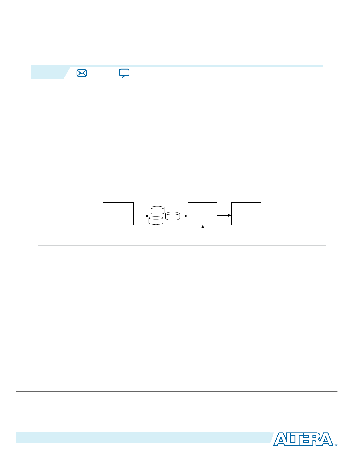
The Altera Remote Update IP core implements a remote system update using dedicated remote system
upgrade circuitry available in supported devices.
Remote system update helps you deliver feature enhancements and bug fixes without recalling your
product, and reduces time-to-market and extends product life. The Altera Remote Update IP core
downloads a new configuration image from a remote location, stores the image in a configuration device,
and upgrades the configuration circuitry to start a reconfiguration cycle.
The dedicated circuitry performs error detection during and after the configuration process. When the
dedicated circuitry detects errors, the circuitry facilitates system recovery by reverting back to a safe,
default factory configuration image and then provides error status information.
The following figure shows a functional diagram for a typical remote system update process.
Figure 1: Typical Remote System Update Process
Note:
Related Information
• Configuration Center
• ALTREMOTE_UPDATE Knowledge Base
Installing and Licensing IP Cores
The Altera IP Library provides many useful IP core functions for your production use without purchasing
an additional license.The OpenCore® feature allows evaluation of any Altera® IP core in simulation and
compilation in the Quartus® II software. Some Altera IP cores, such as MegaCore® functions, require that
you purchase a separate license for production use. The OpenCore Plus feature allows you to evaluate IP
that requires purchase of an additional license. Use these features to evaluate the IP core until you are
satisfied with the functionality and performance. After you purchase a license, visit the Self Service
Licensing Center to obtain a license number for any Altera product.
©
2015 Altera Corporation. All rights reserved. ALTERA, ARRIA, CYCLONE, ENPIRION, MAX, MEGACORE, NIOS, QUARTUS and STRATIX words and logos are
trademarks of Altera Corporation and registered in the U.S. Patent and Trademark Office and in other countries. All other words and logos identified as
trademarks or service marks are the property of their respective holders as described at www.altera.com/common/legal.html. Altera warrants performance
of its semiconductor products to current specifications in accordance with Altera's standard warranty, but reserves the right to make changes to any
products and services at any time without notice. Altera assumes no responsibility or liability arising out of the application or use of any information,
product, or service described herein except as expressly agreed to in writing by Altera. Altera customers are advised to obtain the latest version of device
specifications before relying on any published information and before placing orders for products or services.
Altera recommends you to use 20–MHz f
for all devices.
MAX
ISO
9001:2008
Registered
Page 2

acds
quartus - Contains the Quartus II software
ip - Contains the Altera IP Library and third-party IP cores
altera - Contains the Altera IP Library source code
<IP core name> - Contains the IP core source files
2
Customizing and Generating IP Cores
Figure 2: IP Core Installation Path
Note: The default IP installation directory on Windows is <drive>:\altera\<version number>; on Linux it is
<home directory>/altera/ <version number>.
Related Information
• Altera Licensing Site
• Altera Software Installation and Licensing Manual
Customizing and Generating IP Cores
You can customize IP cores to support a wide variety of applications. The Quartus II IP Catalog and
parameter editor allow you to quickly select and configure IP core ports, features, and output files.
UG-31005
2015.04.07
IP Catalog and Parameter Editor
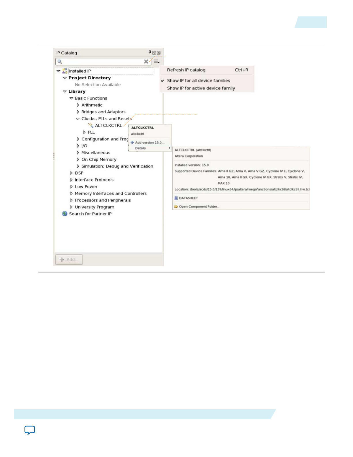
The Quartus II IP Catalog (Tools > IP Catalog) and parameter editor help you easily customize and
integrate IP cores into your project. You can use the IP Catalog and parameter editor to select, customize,
and generate files representing your custom IP variation.
Note:
The IP Catalog lists installed IP cores available for your design. Double-click any IP core to launch the
parameter editor and generate files representing your IP variation. The parameter editor prompts you to
specify an IP variation name, optional ports, and output file generation options. The parameter editor
generates a top-level Qsys system file (.qsys) or Quartus II IP file (.qip) representing the IP core in your
project. You can also parameterize an IP variation without an open project.
Use the following features to help you quickly locate and select an IP core:
• Filter IP Catalog to Show IP for active device family or Show IP for all device families.
• Search to locate any full or partial IP core name in IP Catalog. Click Search for Partner IP, to access
• Right-click an IP core name in IP Catalog to display details about supported devices, open the IP core's
The IP Catalog (Tools > IP Catalog) and parameter editor replace the MegaWizard™ Plug-In
Manager for IP selection and parameterization, beginning in Quartus II software version 14.0. Use
the IP Catalog and parameter editor to locate and paramaterize Altera IP cores.
partner IP information on the Altera website.
installation folder, and view links to documentation.
Altera Corporation
Altera Remote Update IP Core User Guide
Send Feedback
Page 3
Search and filter IP for your target device
Double-click to customize, right-click for
detailed information
UG-31005
2015.04.07
Figure 3: Quartus II IP Catalog
Using the Parameter Editor
3
Note: The IP Catalog is also available in Qsys (View > IP Catalog). The Qsys IP Catalog includes
exclusive system interconnect, video and image processing, and other system-level IP that are not
available in the Quartus II IP Catalog. For more information about using the Qsys IP Catalog, refer
to Creating a System with Qsys in the Quartus II Handbook.
Using the Parameter Editor
The parameter editor helps you to configure IP core ports, parameters, and output file generation options.
• Use preset settings in the parameter editor (where provided) to instantly apply preset parameter values
for specific applications.
• View port and parameter descriptions, and links to documentation.
• Generate testbench systems or example designs (where provided).
Altera Remote Update IP Core User Guide
Send Feedback
Altera Corporation
Page 4
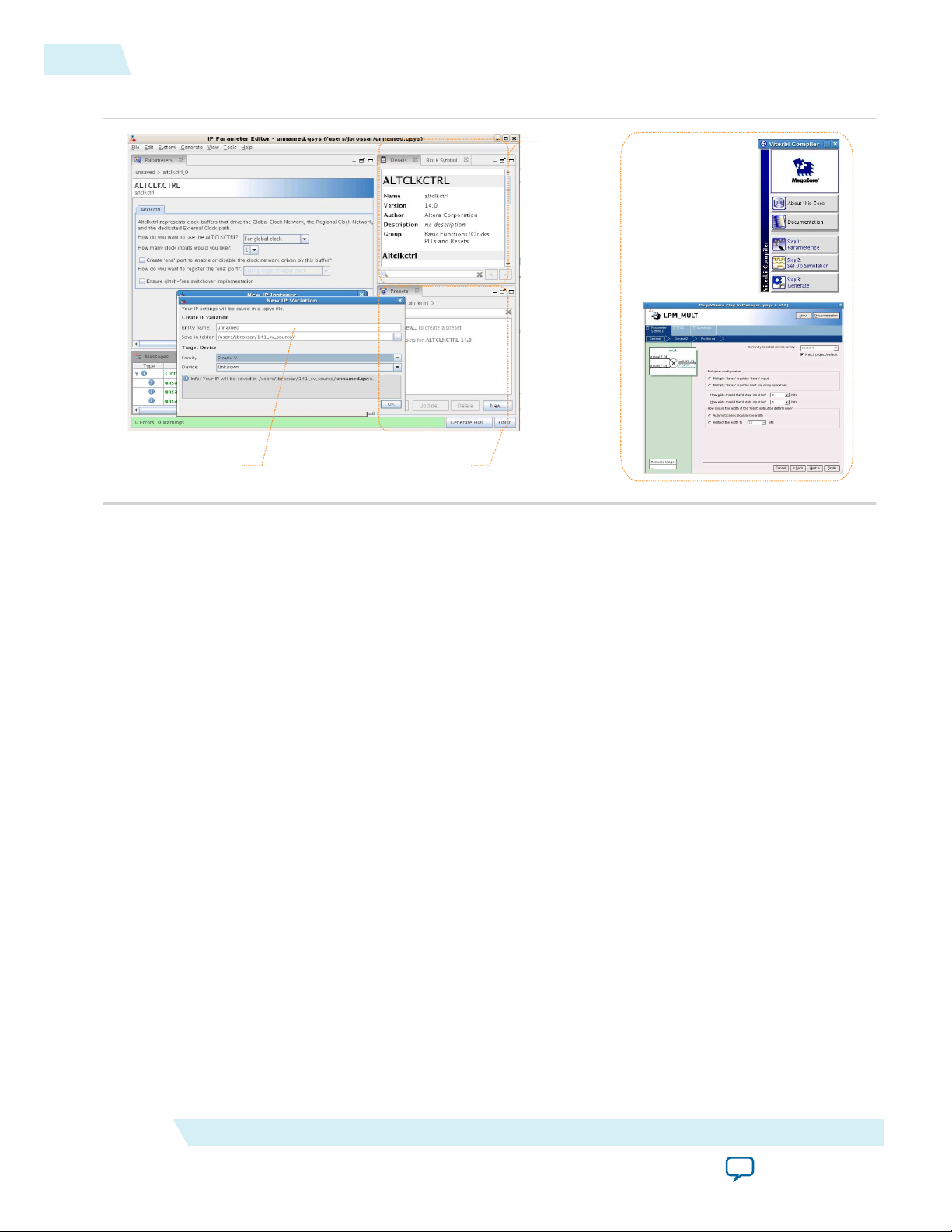
View IP port
and parameter
details
Apply preset parameters for
specific applications
Specify your IP variation name
and target device
Legacy parameter
editors
4
Specifying IP Core Parameters and Options
Figure 4: IP Parameter Editors
UG-31005
2015.04.07
Specifying IP Core Parameters and Options
The parameter editor GUI allows you to quickly configure a custom IP variation. Use the following steps
to specify IP core options and parameters in the Quartus II software.Refer to Specifying IP Core
Parameters and Options (Legacy Parameter Editors) for configuration of IP cores using the legacy
parameter editor.
1. In the IP Catalog (Tools > IP Catalog), locate and double-click the name of the IP core to customize.
The parameter editor appears.
2. Specify a top-level name for your custom IP variation. The parameter editor saves the IP variation
settings in a file named <your_ip>.qsys. Click OK.
3. Specify the parameters and options for your IP variation in the parameter editor, including one or
more of the following. Refer to your IP core user guide for information about specific IP core
parameters.
• Optionally select preset parameter values if provided for your IP core. Presets specify initial
parameter values for specific applications.
• Specify parameters defining the IP core functionality, port configurations, and device-specific
features.
• Specify options for processing the IP core files in other EDA tools.
4. Click Generate HDL, the Generation dialog box appears.
5. Specify output file generation options, and then click Generate. The IP variation files generate
according to your specifications.
6. To generate a simulation testbench, click Generate > Generate Testbench System.
Altera Corporation
Altera Remote Update IP Core User Guide
Send Feedback
Page 5
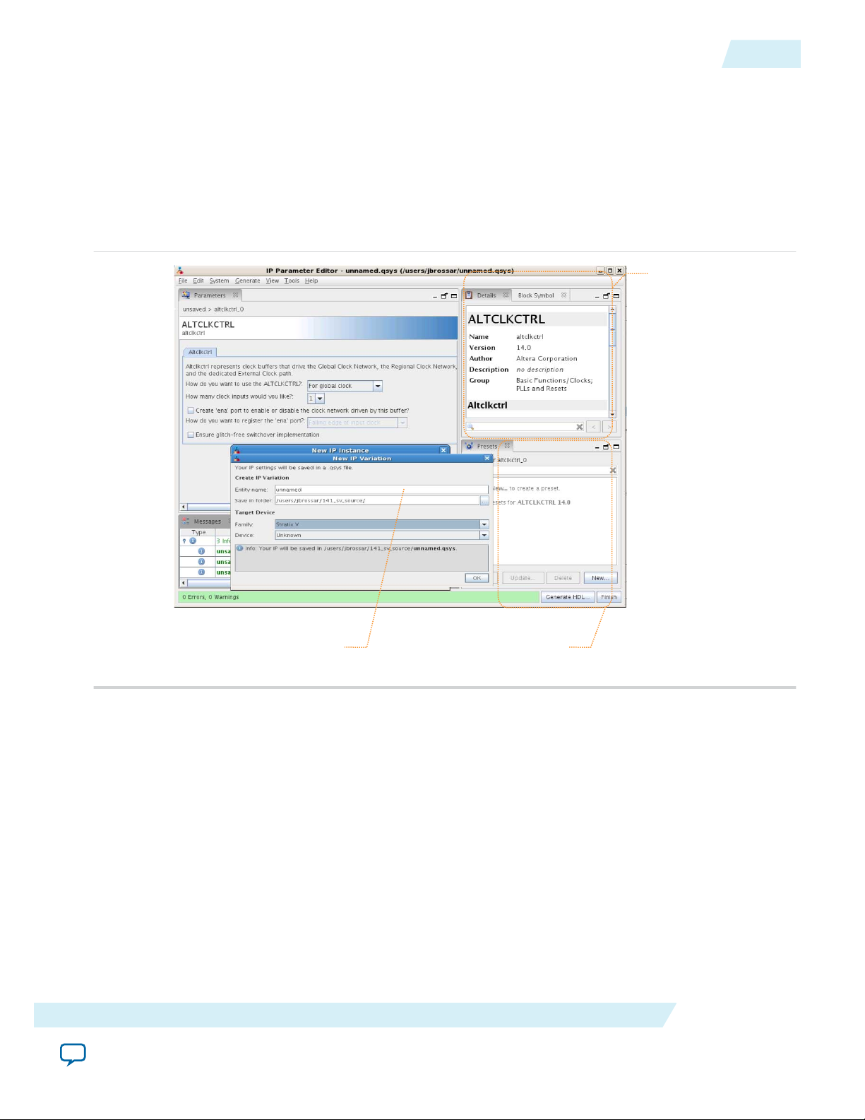
View IP port
and parameter
details
Apply preset parameters for
specific applications
Specify your IP variation name
and target device
UG-31005
2015.04.07
Upgrading IP Cores
7. To generate an HDL instantiation template that you can copy and paste into your text editor, click
Generate > HDL Example.
8. Click Finish. The parameter editor adds the top-level .qsys file to the current project automatically. If
you are prompted to manually add the .qsys file to the project, click Project > Add/Remove Files in
Project to add the file.
9. After generating and instantiating your IP variation, make appropriate pin assignments to connect
ports.
Figure 5: IP Parameter Editor
5
Upgrading IP Cores
IP core variants generated with a previous version of the Quartus II software may require upgrading
before use in the current version of the Quartus II software. Click Project > Upgrade IP Components to
identify and upgrade IP core variants.
The Upgrade IP Components dialog box provides instructions when IP upgrade is required, optional, or
unsupported for specific IP cores in your design. You must upgrade IP cores that require upgrade before
you can compile the IP variation in the current version of the Quartus II software. Most Altera IP cores
support automatic upgrade.
Note:
Altera Remote Update IP Core User Guide
Send Feedback
Upgrading IP cores for Arria 10 and later devices appends a unique identifier to the original IP
core entity name(s), while leaving the IP instance name(s) in tact. There is no requirement to
update these entity references in any supporting Quartus II file, such as the Quartus II Settings File
(.qsf), Synopsys Design Constraints File (.sdc), or SignalTap File (.stp). The Quartus II software
Altera Corporation
Page 6

6
Upgrading IP Cores
reads only the instance name and ignores entity names in paths that specify both entity and
instance names. The upgrade process preserves the original IP variation file (.v, .sv, or .vhd) as
<my_variant>_BAK.v, .sv, .vhd in the project directory.
Table 1: IP Core Upgrade Status
IP Core Status Corrective Action
UG-31005
2015.04.07
Required Upgrade IP
Components
You must upgrade the IP variation before compiling in the current version of
the Quartus II software. Refer to the Description for details about IP core
version differences.
Optional Upgrade IP
Components
Upgrade is optional for this IP variation in the current version of the Quartus
II software. You can upgrade this IP variation to take advantage of the latest
development of this IP core. Alternatively you can retain previous IP core
characteristics by declining to upgrade. Refer to the Description for details
about IP core version differences.
Upgrade Unsupported Upgrade of the IP variation is not supported in the current version of the
Quartus II software due to IP core end of life or incompatibility with the
current version of the Quartus II software. You are prompted to replace the
obsolete IP core with a current equivalent IP core from the IP Catalog. Refer to
the Description for details about IP core version differences and links to
Release Notes.
1. In the latest version of the Quartus II software, open the Quartus II project containing an outdated IP
core variation. The Upgrade IP Components dialog automatically displays the status of IP cores in
your project, along with instructions for upgrading each core. Click Project > Upgrade IP
Components to access this dialog box manually.
2. To upgrade one or more IP cores that support automatic upgrade, ensure that the Auto Upgrade
option is turned on for the IP core(s), and then click Perform Automatic Upgrade. The Status and
Version columns update when upgrade is complete. Example designs provided with any Altera IP core
regenerate automatically whenever you upgrade an IP core.
Altera Corporation
Altera Remote Update IP Core User Guide
Send Feedback
Page 7
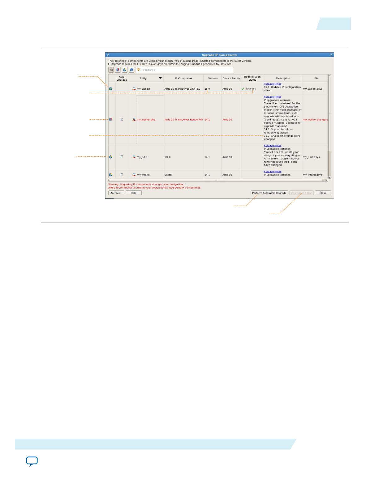
Runs “Auto Upgrade” on all supported outdated cores
Opens editor for manual IP upgrade
“Auto Upgrade”
supported
Upgrade required
Upgrade
optional
Upgrade details
“Auto Upgrade”
successful
UG-31005
2015.04.07
Figure 6: Upgrading IP Cores
Upgrading IP Cores
7
Altera Remote Update IP Core User Guide
3. To manually upgrade an individual IP core that does not support automatic upgrade, select the IP core
and then click Upgrade in Editor. The parameter editor opens, allowing you to adjust parameters and
regenerate the latest version of the IP core.
You upgrade IP cores at the command line as long as the IP core supports auto upgrade. IP cores that
do not support automatic upgrade do not support command line upgrade.
• To upgrade a single IP core that supports auto-upgrade, type the following command:
quartus_sh –ip_upgrade –variation_files <my_ip_filepath/my_ip>.<hdl>
<qii_project>
Example:
quartus_sh -ip_upgrade -variation_files mega/pll25.v hps_testx
• To simultaneously upgrade multiple IP cores that support auto-upgrade, type the following
command:
quartus_sh –ip_upgrade –variation_files “<my_ip_filepath/my_ip1>.<hdl>;
<my_ip_filepath/my_ip2>.<hdl>” <qii_project>
Example:
quartus_sh -ip_upgrade -variation_files "mega/pll_tx2.v;mega/pll3.v" hps_testx
Note:
IP cores older than Quartus II software version 12.0 do not support upgrade. Altera verifies that
the current version of the Quartus II software compiles the previous version of each IP core.
The Altera IP Release Notes reports any verification exceptions for Altera IP cores. Altera does
not verify compilation for IP cores older than the previous two releases.
Altera Corporation
Send Feedback
Page 8
Post-fit timing
simulation netlist
Post-fit timing
simulation (3)
Post-fit functional
simulation netlist
Post-fit functional
simulation
Analysis & Synthesis
Fitter
(place-and-route)
TimeQuest Timing Analyzer
Device Programmer
Quartus II
Design Flow
Gate-Level Simulation
Post-synthesis
functional
simulation
Post-synthesis functional
simulation netlist
(Optional) Post-fit
timing simulation
RTL Simulation
Design Entry
(HDL, Qsys, DSP Builder)
Altera Simulation
Models
EDA
Netlist
Writer
8
Simulating Altera IP Cores in other EDA Tools
Related Information
Altera IP Release Notes
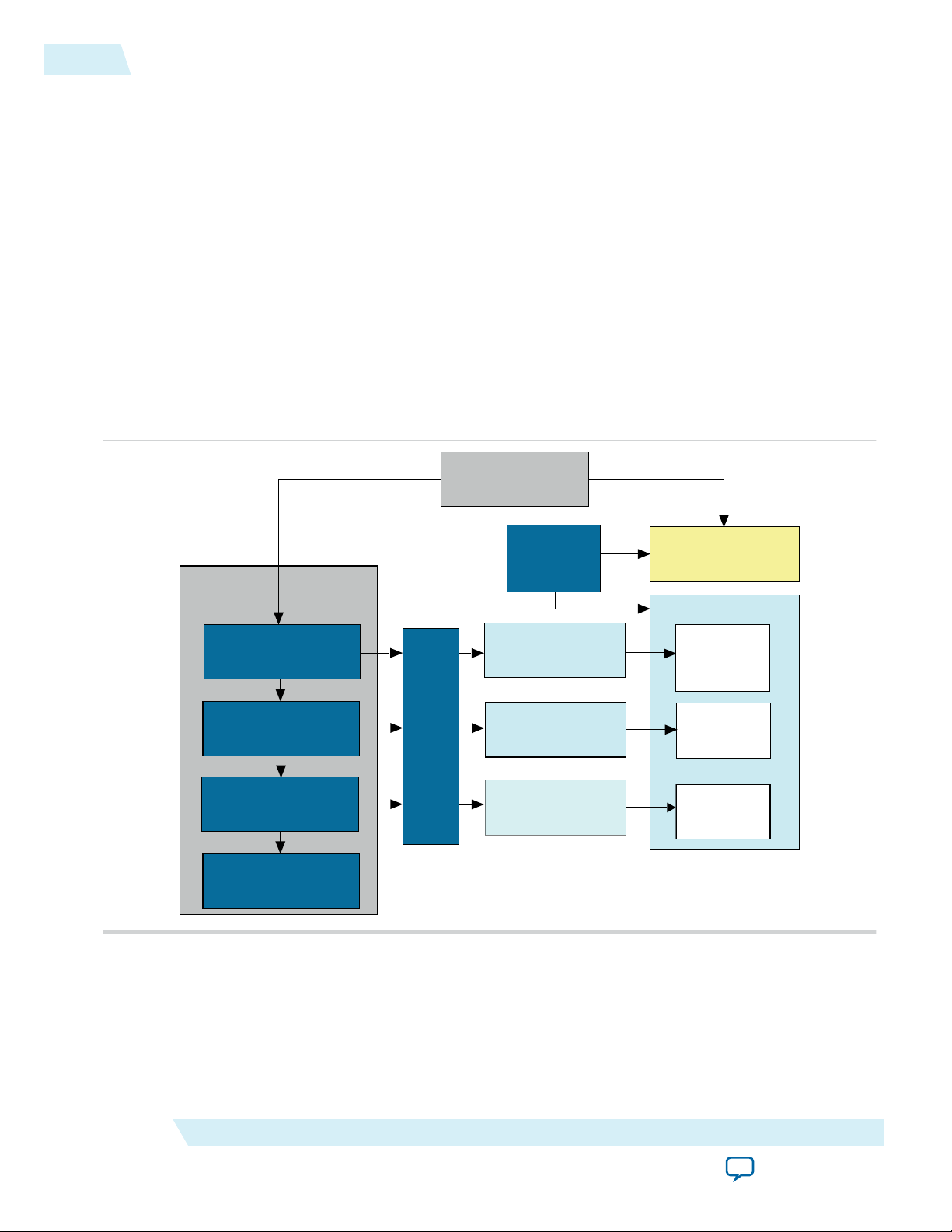
Simulating Altera IP Cores in other EDA Tools
The Quartus II software supports RTL and gate-level design simulation of Altera IP cores in supported
EDA simulators. Simulation involves setting up your simulator working environment, compiling
simulation model libraries, and running your simulation.
You can use the functional simulation model and the testbench or example design generated with your IP
core for simulation. The functional simulation model and testbench files are generated in a project
subdirectory. This directory may also include scripts to compile and run the testbench. For a complete list
of models or libraries required to simulate your IP core, refer to the scripts generated with the testbench.
You can use the Quartus II NativeLink feature to automatically generate simulation files and scripts.
NativeLink launches your preferred simulator from within the Quartus II software.
Figure 7: Simulation in Quartus II Design Flow
UG-31005
2015.04.07
Altera Corporation
Note: Post-fit timing simulation is supported only for Stratix IV and Cyclone IV devices in the current
version of the Quartus II software. Altera IP supports a variety of simulation models, including
simulation-specific IP functional simulation models and encrypted RTL models, and plain text
RTL models. These are all cycle-accurate models. The models support fast functional simulation of
your IP core instance using industry-standard VHDL or Verilog HDL simulators. For some cores,
only the plain text RTL model is generated, and you can simulate that model. Use the simulation
Altera Remote Update IP Core User Guide
Send Feedback
Page 9
After POR or
nCONFIG Assertion
Read Start Address
from Flash
Load Application
Number POF
After POR or
nCONFIG Assertion
Load Factory POF
Enter Factory
User Mode
Enter Application
User Mode
Reconfiguration
or Start Address = 0
Reconfiguration
or Start Address = 0
Reconfiguration &
Start Address > 0 and not 32
Error Count > 3
Watchdog
Timeout
Error Count <= 3
No Error
Factory Configuration Application Configuration
Reconfiguration &
Start Address = 32
Reconfiguration &
Start Address = 32
Reconfiguration &
Start Address > 0
and not 32
UG-31005
2015.04.07
models only for simulation and not for synthesis or any other purposes. Using these models for
synthesis creates a nonfunctional design.
Related Information
Simulating Altera Designs
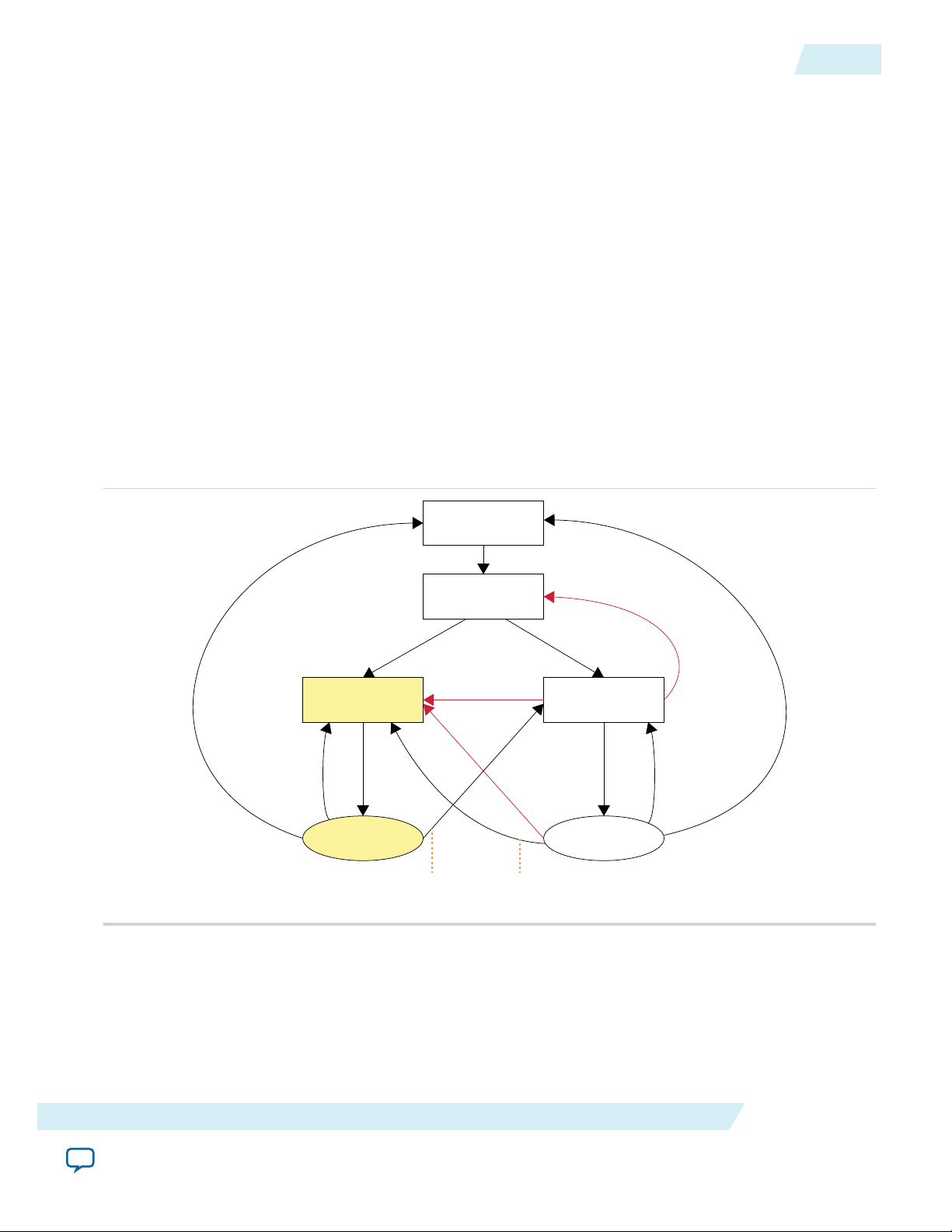
Arria 10 Devices
This section covers the remote system configuration modes, components, parameter, ports, and
parameter settings for Arria® 10 devices.
Remote System Configuration Mode
Arria 10 devices support remote configuration mode only.
Remote configuration supports “Direct to application” and “Application to Application” update. Remote
configuration only supports 4-bytes address scheme so there is no support for devices with densities
smaller than 128Mbit.
Figure 8: Transitions Between Factory and Application Configurations in Remote Update Mode
Arria 10 Devices
9
When used with low-voltage quad-serial configuration (EPCQ-L) devices, the remote update mode allows
a configuration space to start at any flash sector boundary, allowing a maximum of 512 pages in the
EPCQ-L256 device and 1024 pages in the EPCQ-L512 device, in which the minimum size of each page is
512Kbits. Additionally, the remote update mode features a user watchdog timer that can detect functional
errors in an application configuration.
Altera Remote Update IP Core User Guide
Send Feedback
Altera Corporation
Page 10

10
Remote System Configuration Components
Remote System Configuration Components
Table 2: Remote System Configuration Components in Arria 10 Devices
Components Details
UG-31005
2015.04.07
Page mode feature
Factory configuration
Application configuration
Watchdog timer
The dedicated 32-bit start address register PGM[31..0] holds the start address.
Factory configuration can be set as the default configuration setup depends on
the address pointer set.
The factory configuration loads into the device upon power-up.
If a system encounters an error while loading application configuration data
or if the device reconfigures due to nCONFIG assertion, the device loads the
factory configuration. The remote system configuration register determines
the reason for factory configuration. Based on this information, the factory
configuration determines which application configuration to load.
Application configuration can be the default configuration setup depends on
the address pointer set.
The application configuration loads into the device upon power-up.
The application configuration is the configuration data from a remote source
and the data is stored in different locations or pages of the memory storage
device, excluding the factory page.
A watchdog timer is a circuit that determines the functionality of another
mechanism. The watchdog timer functions like a time delay relay that remains
in the reset state while an application runs properly.
Remote update sub-block
Altera Corporation
Arria 10 devices are equipped with a built-in watchdog timer for remote
system configuration to prevent a faulty application configuration from
indefinitely stalling the device.
The timer is a 29-bit counter, but you use only the upper 12 bits to set the
value for the watchdog timer.
The timer begins counting after the device goes into user mode. If the applica‐
tion configuration does not reset the user watchdog timer before time expires,
the dedicated circuitry reconfigures the device with the factory configuration
and resets the user watchdog timer.
To ensure the application configuration is valid, you must continuously reset
the watchdog reset_time within a specific duration during user mode
operation.
The remote update sub-block manages the remote configuration feature. A
remote configuration state machine controls this sub-block. This sub-block
generates the control signals required to control the various configuration
registers.
Altera Remote Update IP Core User Guide
Send Feedback
Page 11

UG-31005
2015.04.07
Components Details
Parameter Settings
11
Remote configuration
registers
The remote configuration registers keep track of page addresses and the cause
of configuration errors. You can control both the update and shift registers.
The status and control registers are controlled by internal logic, but are read
via the shift register. The control register is 38-bit wide.
For details about configuration registers, refer to the Configuration, Design
Security, and Remote System Upgrades chapter in the respective device
handbook.
Parameter Settings
Table 3: Altera Remote Update IP Core Parameters for Arria 10 Devices
GUI Name Legal Value in GUI Description
Which operation mode
will you be using?
Which configuration
device will you be using?
Add support for writing
configuration parameters
REMOTE Specifies the configuration mode of the ALTERA
REMOTE UPDATE IP core.
EPCQ-L device Choose the configuration device you are using.
—
Enable this if you need to write configuration
parameters.
Enable reconfig POF
—
Not available as it is not required
checking
Ports
Table 4: Altera Remote Update IP Core Ports for Arria 10 Devices
Name Port Required? Description
read_param
Input
No Read signal for the parameter specified in param[]
input port and fed to data_out[] output port.
Signal indicating the parameter specified on the
param[] port should be read. The number of bits set
on data_out[] depends on the parameter type. The
signal is sampled at the rising clock edge. Assert the
signal for only one clock cycle to prevent the
parameter from being read again in a subsequent
clock cycle.
The busy signal is activated as soon as read_param is
read as active. While the parameter is being read, the
busy signal remains asserted, and data_out[] has
invalid data. When the busy signal is deactivated,
data_out[] is valid, another parameter can be read.
Altera Remote Update IP Core User Guide
Send Feedback
Altera Corporation
Page 12

12
Ports
Name Port Required? Description
UG-31005
2015.04.07
write_param
param[]
Input
Input
No Write signal for parameter specified in param[] and
with value specified in data_in[].
Signal indicating parameter specified with param[]
should be written into remote update block with the
value specified in data_in[]. The number of bits
read from data_in[] depends on the parameter type.
The signal is sampled at the rising clock edge. The
signal should be asserted for only one clock cycle to
prevent the parameter from being rewritten on a
subsequent clock cycle. The busy signal is activated as
soon as write_param is read as being active. While
the parameter is being written, the busy signal
remains asserted, and input to data_ in[] is ignored.
When the busy signal is deactivated, another
parameter can be written. This signal is only valid in
Factory configuration mode because parameters
cannot be written in Application configuration mode.
The signal cannot be used in Local update mode.
No Bus that specifies which parameter need to be read or
updated.
A 3-bit bus that selects the parameter to be read or
updated. If left unconnected, the default value for this
port is 000.
data_in[]
reconfig
Input
Input
No Data input for writing parameter data into the remote
update block. Input bus for parameter data.
For some parameters, not all bits are used. In this
case, the lower-order bits are used (for example,
status values use bits [4:0]).
If left unconnected, this bus defaults to 0. The port is
ignored if the current configuration is the Application
configuration.
A 32-bit bus width(4-bytes addressing configuration
device, for example EPCQ-L256) in the Quartus II
software version 14.0 or later.
Yes Signal indicating that reconfiguration of the part
should begin using the current parameter settings. A
value of 1 indicates reconfiguration should begin.
This signal is ignored while busy is asserted to ensure
all parameters are completely written before reconfi‐
guration begins.
Altera Corporation
Altera Remote Update IP Core User Guide
Send Feedback
Page 13

UG-31005
2015.04.07
Name Port Required? Description
Ports
13
reset_timer
clock
reset
Input
Input
Input
No Reset signal for watchdog timer.
Signal indicating the internal watchdog timer should
be reset. Unlike other inputs, this signal is not
affected by the busy signal and can reset the timer
even when busy is asserted.
A falling edge of this signal triggers a reset of the user
watchdog timer.
This signal cannot be used in local update mode.
For the timing specification of this parameter, refer to
the specific device handbook.
Yes Clock input to the remote update block.
Clock input to control the machine and to drive the
remote update block during the update of parameters.
This port must be connected to a valid clock.
Yes This is an active high signal. Asserting this signal high
will reset the IP core.
Asynchronous reset input to the IP core to initialize
the machine to a valid state. The machine must be
reset before first use, otherwise the state is not
guaranteed to be valid.
busy
Output
No Busy signal that indicates when remote update block
is reading or writing data.
While this signal is asserted, the machine ignores
most of its inputs and cannot be altered until the
machine deasserts this signal. Therefore, changes are
made only when the machine is not busy.
This signal goes high when read_param or write_
param is asserted, and remains high until the read or
write operation completes.
Altera Remote Update IP Core User Guide
Send Feedback
Altera Corporation
Page 14

14
Parameters
Name Port Required? Description
UG-31005
2015.04.07
data_out[]
ctl_nupt
Output
Input
No Data output when reading parameters.
This bus holds read parameter data from the remote
update block. The param[] value specifies the
parameter to read.Whenthe read_param signal is
asserted, the parameter value is loaded and driven on
this bus. Data is valid when the busy signal is
deasserted.
If left unconnected, the default value for the port is 0.
The width of this bus is device-dependent. For the
Quartus II software version 14.0 and onwards, the bus
widths is 32-bit bus width—using 4-byte addressing
configuration device, for example EPCQL-256.
Yes This port allows you to select which register to be
read whenever read_param operation is running.
• A logic high will select the Control Register—
register containing the current RU settings such as
watchdog timer settings, configuration mode
(AnF) and page address.
• A logic low will select the Update Register—
register containing similar data as held in Control
Register, but the values is updated via write_
param operation to be used in next reconfigura‐
tion.
Parameters
For Arria 10 devices, mapping to each parameter type and corresponding parameter bit width is defined
as follow:
Table 5: Parameter Type and Corresponding Parameter Bit Width Mapping
Bit Parameter Width Comments
• Bit 4—wdtimer_source: User Watchdog Timer
timeout.
• Bit 3—nconfig_source: External configuration
reset (nCONFIG) assertion.
• Bit 2—runconfig_source: Configuration reset
triggered from logic array.
• Bit 1—nstatus_source: nSTATUS asserted by an
external device as the result of an error.
• Bit 0—crcerror_source: CRC error during
application configuration
The POR value for all bits are 0.
Illegal Value
000
001
Reconfiguration trigger
conditions (Read Only)
5
Altera Corporation
Altera Remote Update IP Core User Guide
Send Feedback
Page 15

UG-31005
2015.04.07
Arria II, Arria V, Cyclone V, Stratix IV, and Stratix V Devices
Bit Parameter Width Comments
010 Watchdog Timeout Value 12 —
011 Watchdog Enable 1 —
15
100 Page Select 32
For the Quartus II software version 14.0 and onwards:
• Width of 32 when reading and writing the start
address.
• For active serial devices using 32-bit addressing,
such as EPCQL-256, PGM[31..2] corresponds to
the upper 30 bits of the 32-bits start address.
PGM[1..0] is read as 2'b0.
101 Configuration Mode (AnF) 1
In local update mode, this parameter can only be read.
This parameter is set to 1 in application page and is set
to 0 in factory page. In remote update mode, this
parameter can be read and written.
Before loading the application page in remote update
mode, Altera recommends that you set this parameter
to 1. The content of the control register cannot be read
properly if you fail to do so.
110 Illegal Value
111 Illegal Value
Arria II, Arria V, Cyclone V, Stratix IV, and Stratix V Devices
This section covers the remote system configuration modes, components, parameter, ports, and
parameter settings for Arria II, Arria V, Cyclone® V, Stratix® IV, and Stratix V devices.
Remote System Configuration Mode
Arria II, Arria V, Cyclone V, Stratix IV, and Stratix V devices support remote configuration mode only.
Altera Remote Update IP Core User Guide
Send Feedback
Altera Corporation
Page 16

Power Up
Set Control Register
and Reconfigure
Reload a Different Application
Reload a Different Application
Set Control Register
and Reconfigure
Configuration
Error
Configuration Error
Configuration Error
Application 1
Configuration
Application n
Configuration
Factory
Configuration
(page 0)
16
Remote System Configuration Components
Remote Configuration Mode
Figure 9: Remote Configuration Mode
When used with serial configuration (EPCS) or quad-serial configuration (EPCQ) devices, the remote
update mode allows a configuration space to start at any flash sector boundary, allowing a maximum of
128 pages in the EPCS64 device and 32 pages in the EPCS16 device, in which the minimum size of each
page is 512Kbits. Additionally, the remote update mode features a user watchdog timer that can detect
functional errors in an application configuration.
UG-31005
2015.04.07
Altera Corporation
Remote System Configuration Components
Table 6: Remote System Configuration Components in Arria II, Arria V, Cyclone V, Stratix IV, and Stratix V
Devices
Components Details
Page mode feature
Factory configuration
Application configuration
The dedicated 24-bit start address register PGM[23..0] holds the start
address.
Factory configuration is the default configuration setup.
In remote configuration mode, the factory configuration loads into the
device upon power-up.
If a system encounters an error while loading application configuration
data or if the device reconfigures due to nCONFIG assertion, the device
loads the factory configuration. The remote system configuration
register determines the reason for factory configuration. Based on this
information, the factory configuration determines which application
configuration to load.
The application configuration is the configuration data from a remote
source and the data is stored in different locations or pages of the
memory storage device, excluding the factory default page.
Altera Remote Update IP Core User Guide
Send Feedback
Page 17

UG-31005
2015.04.07
Components Details
Parameter Settings
17
Watchdog timer
Remote update sub-block
A watchdog timer is a circuit that determines the functionality of
another mechanism. The watchdog timer functions like a time delay
relay that remains in the reset state while an application runs properly.
Arria II, Arria V, Cyclone V, Stratix IV, and Stratix V devices are
equipped with a built-in watchdog timer for remote system configura‐
tion to prevent a faulty application configuration from indefinitely
stalling the device.
The timer is a 29-bit counter, but you use only the upper 12 bits to set
the value for the watchdog timer.
The timer begins counting after the device goes into user mode. If the
application configuration does not reset the user watchdog timer
before time expires, the dedicated circuitry reconfigures the device
with the factory configuration and resets the user watchdog timer.
To ensure the application configuration is valid, you must continu‐
ously reset the watchdog reset_time within a specific duration during
user mode operation.
The remote update sub-block manages the remote configuration
feature. A remote configuration state machine controls this sub-block.
This sub-block generates the control signals required to control the
various configuration registers.
Remote configuration registers
The remote configuration registers keep track of page addresses and
the cause of configuration errors. You can control both the update and
shift registers. The status and control registers are controlled by
internal logic, but are read via the shift register. The control register is
38-bit wide.
For details about configuration registers, refer to the Configuration,
Design Security, and Remote System Upgrades chapter in the
respective device handbook.
Parameter Settings
Table 7: Altera Remote Update IP Core Parameters for Arria II, Arria V, Cyclone V, Stratix IV, and Stratix V
Devices
GUI Name Legal Value in GUI Description
Which operation mode
will you be using?
Which configuration
device will you be using?
REMOTE Specifies the configuration mode.
• EPCS device
Choose the configuration device you are using.
• EPCQ device
Altera Remote Update IP Core User Guide
Send Feedback
Altera Corporation
Page 18

18
Ports
GUI Name Legal Value in GUI Description
UG-31005
2015.04.07
Add support for writing
configuration parameters
Enable reconfig POF
checking
—
—
Enable this if you need to write configuration
parameters.
Allows you to enable .pof checking, which allows the
remote update block to verify the existence of an
application configuration image before the image is
loaded. When you turn on this parameter, the Altera
Remote Update IP core checks the .pof and sends the
reconfig signal. This option is disabled by default.
POF checking feature detect and verify the existence of an application configuration image before the
image is loaded. Loading an invalid application configuration image may lead to unexpected behaviour of
the FPGA including system failure. Example of invalid application configuration images are:
• A partially programmed application image
• A blank application image
• An application image assigned with a wrong start address
Ports
Table 8: Altera Remote Update IP Core Ports for Arria II, Arria V, Cyclone V, Stratix IV, and Stratix V Devices
Name Port Required
?
Description
read_param
Input
No Read signal for the parameter specified in
param[] input port and fed to data_out[]
output port.
Signal indicating the parameter specified on the
param[] port should be read. The number of bits
set on data_out[] depends on the parameter
type. The signal is sampled at the rising clock
edge. Assert the signal for only one clock cycle to
prevent the parameter from being read again in a
subsequent clock cycle.
The busy signal is activated as soon as read_
param is read as active. While the parameter is
being read, the busy signal remains asserted, and
data_out[] has invalid data. When the busy
signal is deactivated, data_out[] is valid,
another parameter can be read.
Altera Corporation
Altera Remote Update IP Core User Guide
Send Feedback
Page 19

UG-31005
2015.04.07
Ports
19
Name Port Required
write_param
Input
Description
?
No Write signal for parameter specified in param[]
and with value specified in data_in[].
Signal indicating parameter specified with
param[] should be written into remote update
block with the value specified in data_in[]. The
number of bits read from data_in[] depends on
the parameter type.
The signal is sampled at the rising clock edge.
The signal should be asserted for only one clock
cycle to prevent the parameter from being
rewritten on a subsequent clock cycle. The busy
signal is activated as soon as write_param is read
as being active. While the parameter is being
written, the busy signal remains asserted, and
input to data_in[] is ignored. When the busy
signal is deactivated, another parameter can be
written. This signal is only valid in Factory
configuration mode because parameters cannot
be written in Application configuration mode.
The signal cannot be used in Local update mode.
param[]
Input
No Bus that specifies which parameter need to be
read or updated.
A 3-bit bus that selects the parameter to be read
or updated. If left unconnected, the default value
for this port is 000.
For more information, refer to Parameters on
page 23.
Altera Remote Update IP Core User Guide
Send Feedback
Altera Corporation
Page 20

20
Ports
UG-31005
2015.04.07
Name Port Required
data_in[]
reconfig
Input
Input
Description
?
No Data input for writing parameter data into the
remote update block. Input bus for parameter
data.
For some parameters, not all bits are used. In this
case, the lower-order bits are used (for example,
status values use bits [4:0]).
If left unconnected, this bus defaults to 0. The
port is ignored if the current configuration is the
Application configuration.
A 24-bit bus width in the Quartus II software
version 13.0 or earlier. For the Quartus II
software version 13.1 and onwards, the bus
widths are as follow:
• 24-bit bus width—using 3-byte addressing
configuration device, for example EPCS128.
• 32-bit bus width—using 4-byte addressing
configuration device, for example EPCQ256.
Yes Signal indicating that reconfiguration of the part
should begin using the current parameter
settings. A value of 1 indicates reconfiguration
should begin. This signal is ignored while busy is
asserted to ensure all parameters are completely
written before reconfiguration begins.
reset_timer
clock
Input
Input
No Reset signal for watchdog timer.
Signal indicating the internal watchdog timer
should be reset. Unlike other inputs, this signal is
not affected by the busy signal and can reset the
timer even when busy is asserted.
A falling edge of this signal triggers a reset of the
user watchdog timer.
This signal cannot be used in local update mode.
For the timing specification of this parameter,
refer to the specific device handbook.
Yes Clock input to the remote update block.
Clock input to control the machine and to drive
the remote update block during the update of
parameters.
This port must be connected to a valid clock.
Altera Corporation
Altera Remote Update IP Core User Guide
Send Feedback
Page 21

UG-31005
2015.04.07
Ports
21
Name Port Required
reset
busy
data_out[]
Input
Output
Output
Description
?
Yes This is an active high signal. Asserting this signal
high will reset the IP core.
Asynchronous reset input to the IP core to
initialize the machine to a valid state. The
machine must be reset before first use, otherwise
the state is not guaranteed to be valid.
No Busy signal that indicates when remote update
block is reading or writing data.
While this signal is asserted, the machine ignores
most of its inputs and cannot be altered until the
machine deasserts this signal. Therefore, changes
are made only when the machine is not busy.
This signal goes high when read_param or
write_param is asserted, and remains high until
the read or write operation completes.
No Data output when reading parameters.
This bus holds read parameter data from the
remote update block. The param[] value
specifies the parameter to read. When the read_
param signal is asserted, the parameter value is
loaded and driven on this bus. Data is valid when
the busy signal is deasserted.
If left unconnected, the default value for the port
is 0. The width of this bus is device-dependent:
A 24-bit bus width in the Quartus II software
version 13.0 or earlier. For the Quartus II
software version 13.1 and onwards, the bus
widths are as follow:
• 24-bit bus width—using 3-byte addressing
configuration device, for example EPCS128.
• 32-bit bus width—using 4-byte addressing
configuration device, for example EPCQ256.
Altera Remote Update IP Core User Guide
Send Feedback
Altera Corporation
Page 22

22
Ports
UG-31005
2015.04.07
Name Port Required
asmi_busy
asmi_data_valid
Input
Input
Description
?
No Input from the altasmi_parallel component.
Available when the check_app_pof parameter is
set to true.
A logic high on this pin indicates that the
ALTASMI_PARALLEL IP core is busy
processing the operation. The Altera Remote
Update IP core waits for this pin to go low before
initiating another operation.
Wire this pin to the asmi_busy output port of
the ALTASMI_PARALLEL IP core.
No Input from the altasmi_parallel component.
Available when the check_app_pof parameter is
set to true.
A logic high on this pin indicates valid data in
the asmi_dataout[7..0] output port of the
ALTASMI_PARALLEL IP core.
Wire this pin to the asmi_data_valid output
port of the ALTASMI_PARALLEL IP core.
asmi_dataout
pof_error
Input
Output
No Input from the altasmi_parallel component.
Available when the check_app_pof parameter is
set to true.
The Altera Remote Update IP core presents the
address information on this pin before initiating
the read operation on the ALTASMI_
PARALLEL IP core.
No Detects and invalid application configuration
image.
Available when the check_app_pof parameter is
set to TRUE.
A logic high on this pin indicates that the Altera
Remote Update IP core detects an invalid
application configuration image. If asserted high,
you must take corrective action by reloading a
new application configuration image or
specifying a different address location in the
EPCS or EPCQ that contains a valid application
configuration image. Wire this pin based on your
system requirement.
Altera Corporation
Altera Remote Update IP Core User Guide
Send Feedback
Page 23

UG-31005
2015.04.07
Parameters
23
Name Port Required
asmi_addr
asmi_read
asmi_rden
Output
Output
Output
Description
?
No Address signal to altasmi_parallel
component.
Available when the check_app_pof parameter is
set to TRUE. The Altera Remote Update IP core
presents the address information on this pin
before initiating the read operation on the
ALTASMI_PARALLEL IP core.
No Read signal to altasmi_parallel component.
Available when the check_app_pof parameter is
set to TRUE. A logic high on this pin initiates the
read operation on the ALTASMI_PARALLEL IP
core.
Wire this pin to the asmi_read input port of the
ALTASMI_PARALLEL IP core.
No Read enable signal to altasmi_parallel
component.
Available when the check_app_pof parameter is
set to TRUE. This pin enables the read operation
on the ALTASMI_PARALLEL IP core.
Wire this pin to the asmi_rden input port of the
ALTASMI_PARALLEL IP core.
Parameters
For Arria II, Arria V, Cyclone V, Stratix IV, and Stratix V devices, mapping to each parameter type and
corresponding parameter bit width is defined as follow:
Table 9: Parameter Type and Corresponding Parameter Bit Width Mapping
Bit Parameter Width Comments
• Bit 4—wdtimer_source: User Watchdog Timer
timeout.
• Bit 3—nconfig_source: External configuration
reset (nCONFIG) assertion.
• Bit 2—runconfig_source: Configuration reset
triggered from logic array.
• Bit 1—nstatus_source: nSTATUS asserted by an
external device as the result of an error
• Bit 0—crcerror_source: CRC error during
application configuration
The POR value for all bits are 0.
000
Reconfiguration trigger
conditions (Read Only)
5
001
Altera Remote Update IP Core User Guide
Send Feedback
Illegal Value
Altera Corporation
Page 24

24
Cyclone III and Cyclone IV Devices
Bit Parameter Width Comments
010 Watchdog Timeout Value 12 —
011 Watchdog Enable 1 —
UG-31005
2015.04.07
100 Page Select 24 or 32
For the Quartus II software version 13.1 and onwards:
• Width of 24 or 32 when reading and writing the
start address.
• For active serial devices using 24-bit addressing,
such as EPCS128 or EPCQ128, PGM[23..2]
corresponds to the upper 22 bits of the 24-bits start
address. PGM[1..0] is read as 2'b0.
• For active serial devices using 32-bit addressing,
such as EPCQ256, PGM[31..2] corresponds to the
upper 30 bits of the 32-bits start address.
PGM[1..0] is read as 2'b0.
For the Quartus II software version 13.0 and earlier:
• Width of 24 when reading and writing the start
address.
• For Arria II, Stratix III, and Stratix IV devices,
PGM[23..0] form the 24-bit start address.
• For Arria V, Cyclone V, and Stratix V devices, if
you use active serial devices using 24-bit
addressing, such as EPCS128 or EPCQ128,
PGM[23..0] corresponds to the 24 bits of the start
address. If you use active serial devices using 32-bit
addressing, such as EPCQ256, PGM[23..0]
corresponds to the 24 MSB of the start address,
thus the 32 bits start address is PGM[23..0],8'b0.
101
Configuration Mode (AnF) 1
110 Illegal Value
111 Illegal Value
Cyclone III and Cyclone IV Devices
This section covers the remote system configuration modes, components, parameters, ports, and remote
update operation for Cyclone III and Cyclone IV devices.
Altera Corporation
In local update mode, this parameter can only be read.
This parameter is set to 1 in application page and is set
to 0 in factory page. In remote update mode, this
parameter can be read and written.
Before loading the application page in remote update
mode, Altera recommends that you set this parameter
to 1. The content of the control register cannot be read
properly if you fail to do so.
Altera Remote Update IP Core User Guide
Send Feedback
Page 25

Power Up
Set Control Register
and Reconfigure
Reload a Different Application
Reload a Different Application
Set Control Register
and Reconfigure
Configuration
Error
Configuration Error
Configuration Error
Application 1
Configuration
Application n
Configuration
Factory
Configuration
(page 0)
UG-31005
2015.04.07
Remote System Configuration Mode
Cyclone IV devices support remote configuration mode only.
Remote Configuration Mode
Figure 10: Remote Configuration Mode
Remote System Configuration Mode
25
Cyclone IV E devices support the active parallel (AP) configuration scheme for Altera devices.
When used with EPCS or EPCQ devices, the remote update mode allows a configuration space to start at
any flash sector boundary, allowing a maximum of 128 pages in the EPCS64 device and 32 pages in the
EPCS16 device, in which the minimum size of each page is 512Kbits. Additionally, the remote update
mode features a user watchdog timer that can detect functional errors in an application configuration.
Remote System Configuration Components
Table 10: Remote System Configuration Components in Cyclone IV Devices
Components Details
Page mode feature
For both AS and AP configurations, Cyclone IV devices use a 24-bit
boot start address in which you set the most significant 22 bits. Cyclone
devices do not support pgmout ports.
Altera Remote Update IP Core User Guide
Send Feedback
Altera Corporation
Page 26

26
Remote System Configuration Components
Components Details
UG-31005
2015.04.07
Factory configuration
Factory configuration is the default configuration setup.
In remote configuration mode, the factory configuration loads into
Cyclone III and Cyclone IV devices upon power-up.
If a system encounters an error while loading application configuration
data or if the device reconfigures due to nCONFIG assertion, the device
loads the factory configuration. The remote system configuration
register determines the reason for factory configuration. Based on this
information, the factory configuration determines which application
configuration to load.
Upon power-up in remote update in the AP configuration scheme,
Cyclone III and Cyclone IV devices load the default factory configura‐
tion located at the following address:
boot_address[23:0] = 24'h010000 = 24'b1 0000 0000 0000
0000.
You can change the default factory configuration address to any
address using the APFC_BOOT_ADDR JTAG instruction. The factory
image is stored in non-volatile memory and is never updated or
modified using remote access. This corresponds to the default start
address location 0x010000 (or the updated address if the default
address is changed) in the supported parallel flash memory. Note that
0x010000 is the 16-bit word address for the AP flash memory.
However, the Quartus II software implements 8-bit byte addressing.
Therefore, the correct Quartus II software setting for this address is
0x020000.
Application configuration
Altera Corporation
The application configuration is the configuration data from a remote
source and the data is stored in different locations or pages of the
memory storage device, excluding the factory default page.
Altera Remote Update IP Core User Guide
Send Feedback
Page 27

UG-31005
2015.04.07
Components Details
Parameter Settings
27
Watchdog timer
Remote update sub-block
A watchdog timer is a circuit that determines the functionality of
another mechanism. The watchdog timer functions like a time delay
relay that remains in the reset state while an application runs properly.
Cyclone IV devices are equipped with a built-in watchdog timer for
remote system configuration to prevent a faulty application configura‐
tion from indefinitely stalling the device.
The timer is a 29-bit counter, but you use only the upper 12 bits to set
the value for the watchdog timer.
The timer begins counting after the device goes into user mode. If the
application configuration does not reset the user watchdog timer
before time expires, the dedicated circuitry reconfigures the device
with the factory configuration and resets the user watchdog timer.
To ensure the application configuration is valid, you must continu‐
ously reset the watchdog reset_time within a specific duration during
user mode operation.
The remote update sub-block manages the remote configuration
feature. A remote configuration state machine controls this sub-block.
This sub-block generates the control signals required to control the
various configuration registers.
Remote configuration registers
The remote configuration registers keep track of page addresses and
the cause of configuration errors. You can control both the update and
shift registers. The status and control registers are controlled by
internal logic, but are read via the shift register.
For Cyclone IV devices, the remote system upgrade status register has
additional capabilities. Three sets of registers store the status for the
current application configuration and the two previous application
configurations.
For details about configuration registers, refer to the Configuration,
Design Security, and Remote System Upgrades chapter in the
respective device handbook.
Parameter Settings
Table 11: Altera Remote Update IP core Parameters for Cyclone IV Devices
GUI Name Legal Value in GUI Description
Which operation mode
will you be using?
REMOTE Specifies the configuration mode of the Altera Remote
Update IP core.
Altera Remote Update IP Core User Guide
Send Feedback
Altera Corporation
Page 28

28
Ports
GUI Name Legal Value in GUI Description
UG-31005
2015.04.07
Which configuration
device will you be using?
Add support for writing
configuration parameters
Enable reconfig POF
checking
• EPCS device
• EPCQ device
—
—
Choose the configuration device that you are using.
Enable this if you need to write configuration
parameters.
Allows you to enable .pof checking, which allows the
remote update block to verify the existence of an
application configuration image before the image is
loaded. When you turn on this parameter, the Altera
Remote Update IP core checks the .pof and sends the
reconfig signal. This option is disabled by default.
Ports
Table 12: Altera Remote Update IP Core Ports for Cyclone IV Devices
Name Port Required
?
read_param
Input
No Read signal for the parameter specified in
param[] input port and fed to data_out[]
output port.
Description
Signal indicating the parameter specified on the
param[] port should be read. The number of bits
set on data_out[] depends on the parameter
type. The signal is sampled at the rising clock
edge. Assert the signal for only one clock cycle to
prevent the parameter from being read again in a
subsequent clock cycle.
The busy signal is activated as soon as read_
param is read as active. While the parameter is
being read, the busy signal remains asserted, and
data_out[] has invalid data. When the busy
signal is deactivated, data_out[] is valid,
another parameter can be read.
Altera Corporation
Altera Remote Update IP Core User Guide
Send Feedback
Page 29

UG-31005
2015.04.07
Ports
29
Name Port Required
write_param
Input
Description
?
No Write signal for parameter specified in param[]
and with value specified in data_in[].
Signal indicating parameter specified with
param[] should be written into remote update
block with the value specified in data_in[]. The
number of bits read from data_in[] depends on
the parameter type.
The signal is sampled at the rising clock edge.
The signal should be asserted for only one clock
cycle to prevent the parameter from being
rewritten on a subsequent clock cycle. The busy
signal is activated as soon as write_param is read
as being active. While the parameter is being
written, the busy signal remains asserted, and
input to data_in[] is ignored. When the busy
signal is deactivated, another parameter can be
written. This signal is only valid in Factory
configuration mode because parameters cannot
be written in Application configuration mode.
The signal cannot be used in local update mode.
param[]
Input
No Bus that specifies which parameter need to be
read or updated.
A 3-bit bus that selects the parameter to be read
or updated. If left unconnected, the default value
for this port is 000.
For more information, refer to Parameters on
page 34.
Altera Remote Update IP Core User Guide
Send Feedback
Altera Corporation
Page 30

30
Ports
UG-31005
2015.04.07
Name Port Required
data_in[]
reconfig
Input
Input
Description
?
No Data input for writing parameter data into the
remote update block. Input bus for parameter
data.
For some parameters, not all bits are used. In this
case, the lower-order bits are used (for example,
status values use bits [4:0]).
If left unconnected, this bus defaults to 0. The
port is ignored if the current configuration is the
Application configuration.
A 22-bit bus width in the Quartus II software
version 13.0 or earlier. For the Quartus II
software version 13.1 and onwards, the bus
widths are as follow:
• 24-bit bus width—using 3-byte addressing
configuration device, for example EPCS128.
• 32-bit bus width—using 4-byte addressing
configuration device, for example EPCQ256.
Yes Signal indicating that reconfiguration of the part
should begin using the current parameter
settings. A value of 1 indicates reconfiguration
should begin. This signal is ignored while busy is
asserted to ensure all parameters are completely
written before reconfiguration begins.
reset_timer
Input
No Reset signal for watchdog timer.
Signal indicating the internal watchdog timer
should be reset. Unlike other inputs, this signal is
not affected by the busy signal and can reset the
timer even when busy is asserted.
A falling edge of this signal triggers a reset of the
user watchdog timer.
This signal cannot be used in local update mode.
For the timing specification of this parameter,
refer to the specific device handbook.
Altera Corporation
Altera Remote Update IP Core User Guide
Send Feedback
Page 31

UG-31005
2015.04.07
Ports
31
Name Port Required
read_source
clock
Input
Input
Description
?
Yes Specifies whether a parameter value is read from
the current or a previous state.
This 2-bit port specifies the state from which a
parameter value is read. This signal is valid only
when the read_param signal is valid.
Mapping read_source[1..0] to Selected Source
is defined as follow:
• 00 - Current State Content in Status Register
• 01 - Previous State Register 1 Content in
Status Register
• 10 - Previous State Register 2 Content in
Status Register
• 11 - Value in Input Register
For details, refer to the Configuration, Design
Security, and Remote System Upgrades chapter
in the respective device handbook.
Yes Clock input to the remote update block.
Clock input to control the machine and to drive
the remote update block during the update of
parameters.
reset
busy
Input
Output
This port must be connected to a valid clock.
Yes This is an active high signal. Asserting this signal
high will reset the IP core.
Asynchronous reset input to the IP core to
initialize the machine to a valid state. The
machine must be reset before first use, otherwise
the state is not guaranteed to be valid.
No Busy signal that indicates when remote update
block is reading or writing data.
While this signal is asserted, the machine ignores
most of its inputs and cannot be altered until the
machine deasserts this signal. Therefore, changes
are made only when the machine is not busy.
This signal goes high when read_param or
write_param is asserted, and remains high until
the read or write operation completes.
Altera Remote Update IP Core User Guide
Send Feedback
Altera Corporation
Page 32

32
Ports
UG-31005
2015.04.07
Name Port Required
data_out[]
asmi_busy
Output
Input
Description
?
No Data output when reading parameters.
This bus holds read parameter data from the
remote update block. The param[] value
specifies the parameter to read. When the read_
param signal is asserted, the parameter value is
loaded and driven on this bus. Data is valid when
the busy signal is deasserted.
If left unconnected, the default value for the port
is 000. The width of this bus is device-dependent:
A 29-bit bus width in the Quartus II software
version 13.0 or earlier. For the Quartus II
software version 13.1 and onwards, the bus
widths are as follow:
• 29-bit bus width—using 3-byte addressing
configuration device, for example EPCS128.
• 32-bit bus width—using 4-byte addressing
configuration device, for example EPCQ256.
No Input from the altasmi_parallel component.
asmi_data_valid
Input
Available when the check_app_pof parameter is
set to true.
A logic high on this pin indicates that the
ALTASMI_PARALLEL IP core is busy
processing the operation. The Altera Remote
Update IP core waits for this pin to go low before
initiating another operation.
Wire this pin to the asmi_busy output port of
the ALTASMI_PARALLEL IP core.
No Input from the altasmi_parallel component.
Available when the check_app_pof parameter is
set to true.
A logic high on this pin indicates valid data in
the asmi_dataout[7..0] output port of the
ALTASMI_PARALLEL IP core.
Wire this pin to the asmi_data_valid output
port of the ALTASMI_PARALLEL IP core.
Altera Corporation
Altera Remote Update IP Core User Guide
Send Feedback
Page 33

UG-31005
2015.04.07
Ports
33
Name Port Required
asmi_dataout
pof_error
Input
Output
Description
?
No Input from the altasmi_parallel component.
Available when the check_app_pof parameter is
set to true.
The Altera Remote Update IP core presents the
address information on this pin before initiating
the read operation on the ALTASMI_
PARALLEL IP core.
No Detects and invalid application configuration
image.
Available when the check_app_pof parameter is
set to TRUE.
A logic high on this pin indicates that the Altera
Remote Update IP core detects an invalid
application configuration image. If asserted high,
you must take corrective action by reloading a
new application configuration image or
specifying a different address location in the
EPCS or EPCQ that contains a valid application
configuration image. Wire this pin based on your
system requirement.
asmi_addr
asmi_read
Output
Output
No Address signal to altasmi_parallel
component.
Available when the check_app_pof parameter is
set to TRUE. The Altera Remote Update IP core
presents the address information on this pin
before initiating the read operation on the
ALTASMI_PARALLEL IP core.
Wire this pin to the asmi_addr input port of the
ALTASMI_PARALLEL IP core.
No Read signal to altasmi_parallel component.
Available when the check_app_pof parameter is
set to TRUE. A logic high on this pin initiates the
read operation on the ALTASMI_PARALLEL IP
core.
Wire this pin to the asmi_read input port of the
ALTASMI_PARALLEL IP core.
Altera Remote Update IP Core User Guide
Send Feedback
Altera Corporation
Page 34

34
Parameters
UG-31005
2015.04.07
Name Port Required
asmi_rden
Output
?
No Read enable signal to altasmi_parallel
Description
component.
Available when the check_app_pof parameter is
set to TRUE. This pin enables the read operation
on the ALTASMI_PARALLEL IP core.
Wire this pin to the asmi_rden input port of the
ALTASMI_PARALLEL IP core.
Parameters
For Cyclone IV devices, mapping to each parameter type and corresponding parameter bit width is
defined as follow:
Table 13: Mapping to Each Parameter Type and Corresponding Parameter Bit Width
Bit Parameter Width Comments
000 Master State Machine
Current State Mode (Read
Only)
2
00—Factory mode.
01—Application mode.
11—Application mode with the master state machine
user watchdog timer enabled.
001 Force early CONF_DONE
(cd_early) check
1
—
12 Width of 12 when writing.
010 Watchdog Timeout Value
The 12 bits for writing are the upper 12 bits of the 29bit Watchdog Timeout Value
29 Width of 29 when reading.
011 Watchdog Enable 1 —
Altera Corporation
Altera Remote Update IP Core User Guide
Send Feedback
Page 35

UG-31005
2015.04.07
Remote Update Operation
Bit Parameter Width Comments
35
100 Boot Address —
101
110
Force the internal oscillator
as startup state machine
clock (osc_int) option bit
For the Quartus II software version 13.1 and
onwards:
• Width of 29 or 32 when reading the boot address.
• Width of 24 or 32 when writing the boot address.
• For active serial devices using the 24-bit
addressing, such as EPCS128 or EPCQ128, boot_
address[23..2] corresponds to the upper 22 bits
of the 24-bits boot address. boot_address[1..0]
is read as 2'b0.
• For active serial devices using the 32-bit
addressing, such as EPCQ256, boot_
address[31..2] corresponds to the upper 30 bits
of the 32-bits boot address. boot_address[1..0]
is read as 2'b0.
For the Quartus II software version 13.0 or earlier:
• Width of 24 when reading the boot address.
• Width of 22 when writing the boot address.
• Writes the boot address to the upper 22 bits of the
24-bits boot address.
Illegal Value
1 —
111 Reconfiguration trigger
conditions (Read Only)
Remote Update Operation
Note:
Note: Perform remote update operations in the corresponding master state machine (MSM) mode.
read_source specifies whether a parameter value is read from the current or a previous state. For
more information, refer to Table 14.
5
Bit 4 (nconfig_source)—external configuration reset
(nconfig) assertion.
Bit 3 (crcerror_source)—CRC error during
application configuration.
Bit 2 (nstatus_source)—nstatus asserted by an
external device as the result of an error.
Bit 1 (wdtimer_source)—User watchdog timer
timeout.
Bit 0 (runconfig_source)—Configuration reset
triggered from logic array.
Altera Remote Update IP Core User Guide
Send Feedback
Altera Corporation
Page 36

36
Remote Update Operation
UG-31005
2015.04.07
read_
para
m
write
para
read_source param Remote Update Operation data_out
_
m
1 0 [00] [000] Master State Machine Current State Mode
(Read Only)
width
(bits)
2 Factory or
Application
• 00—Factory mode
• 01—Application mode
• 11—Application mode with Master State
Machine User Watchdog Timer Enabled
1 0 [00] [100] Read factory boot address 24 Factory
1 0 [01] [100]
Read Past Status 1 boot address.
24 Factory
For more information, refer to Figure 11.
1 0 [01] [111]
Read Past Status 1 reconfiguration trigger
5 Factory
condition source.
For more information, refer to Figure 11.
1 0 [10] [100]
Read Past Status 2 boot address.
24 Factory
MSM Mode
For more information, refer to Figure 11.
1 0 [10] [111]
Read Past Status 2 reconfiguration trigger
5 Factory
condition source
For more information, refer to Figure 11.
1 0 [01] [010] Read current application mode watchdog
29 Application
value
1 0 [01] [011] Read current application mode watchdog
1 Application
enable
1 0 [10] [100] Read current application mode boot address 24 Application
0 1 [00] [001]
Write the early confdone check bit.
1 Factory
All parameters can be written in factory
mode only.
0 1 [00] [010]
Write the watchdog time-out value.
12 Factory
All parameters can be written in factory
mode only.
Altera Corporation
Altera Remote Update IP Core User Guide
Send Feedback
Page 37

UG-31005
2015.04.07
Remote Update Operation
37
read_
para
m
write
para
read_source param Remote Update Operation data_out
_
m
0 1 [00] [011]
Write the watchdog enable bit.
width
(bits)
1 Factory
All parameters can be written in factory
mode only.
0 1 [00] [100]
Write application boot address.
22 Factory
All parameters can be written in factory
mode only.
0 1 [00] [110] Write to force the internal oscillator as
1 Factory
startup state machine clock. All parameters
can be written in factory mode only.
1 0 [11] [001] Read the early confdone check bits 1 Factory
1 0 [11] [010] Read watchdog time-out value 12 Factory
1 0 [11] [011] Read watchdog enable bit 1 Factory
1 0 [11] [100] Read boot address 22 Factory
MSM Mode
1 0 [11] [110] Read to check whether the internal oscillator
is set as startup state machine clock
read_source
The following table lists the details for read_source. read_source specifies whether a parameter value is
read from the current or a previous state. When you trigger the read operation, all contents in status
register or input register latched to the data_out node in the Altera Remote Update IP core.
Table 14: read_source
read_source Description
00 Current state contents in status register
01 Previous state register 1 contents in status register
10 Previous state register 2 contents in status register
11 Current contents is in input register
State Register
The previous state register 1 reflects the current application configuration and the previous state register 2
reflects the previous application configuration.
1 Factory
Altera Remote Update IP Core User Guide
Send Feedback
Altera Corporation
Page 38

Application 1
Configuration
Application 2
Configuration
Factory
Configuration
Configured the Application 1
from Factory
Switched to Application 2
Back to factory
(State register 1 reflects to current application which is application 1)
Back to factory
(State register 1 reflects to current application which is application 2, while
the state register 2 is reflects to previous application which is application 1)
38
Design Example: Factory Image and Application Image Programming Sequence
Figure 11: State Register
UG-31005
2015.04.07
Design Example: Factory Image and Application Image Programming
Sequence
This design example illustrates the sequence of programming the Factory Image and Application Image
by using the programmer in Quartus II.
In this example, you will be perform the following activities:
• Generate both SRAM object file (.sof) for Application Image and Factory Image.
• Convert Programming file to generate the JTAG indirect configuration file (.jic)
• Program the .jic file into the FPGA
The following instructions guide you to perform the design example tasks:
1. Unzip the contents of the RSU.zip file to your working directory on your PC.
2. In the Quartus II software, click Open Project in the File menu,
3. Compile Application Image:
Altera Corporation
Altera Remote Update IP Core User Guide
Send Feedback
Page 39

UG-31005
2015.04.07
Document Revision History
a. Browse to the folder in which you unzipped the files and open the Application_Image.qpf.
b. Click Yes in the message box "Do you want to overwrite the database for C:/your working
directory/Application_Image.qpf created by Quatus II 64-Bit Version 13.0.a Build 232 Service Pack
1 SJ Full version?"
c. On the Processing menu, choose Start Compilation.
d. Click OK when the full compilation successful dialog box appears.
e. Application_Image.sof will be generated in c:\your working directory\output_files.
f. Click close project in the file menu.
4. 4. Compile Factory Image:
a. Browse to the folder in which you unzipped the files and open the SVRSU.qpf.
b. Click Yes in the message box "Do you want to overwrite the database for C:/your working directory/
Application_Image.qpf created by Quatus II 64-Bit Version 13.0.a Build 232 Service Pack 1 SJ Full
version?"
c. Choose Start Compilation on the Processing menu.
d. Click OK when the full compilation successful dialog box appears.
e. Factory_Image.sof will be generated in c:\your working directory\output_files.
5. On the File Menu, click Convert Programming Files and select the detail as shown below:
• Programming File type: JTAG Indirect Configuration File (.jic)
• Select Configuration Device: EPCQ 128
• Mode: Active Serial x4
• File name: c:/your working directory/output_file.jic
• Flash loader: click add device and choose 5CEFA7ES
• SOFT DATA PAGE_0: click Add File and select the factory image file (SVRSU.sof)
• SOFT DATA PAGE_0: click Add File and select the Application image file (Application_Image.sof)
• Click Generate.
• Click OK when the dialogue box of .jic file successfully generated appears.
6. On the Tool Menu, click Programmer:
39
a. Make sure the board is power up and the USB Blaster is connected between computer and the
board. This design example uses USB Blaster and JTAG mode.
b. Click Auto Detect.
c. Right click on the 5CEFA7ES and select change file.
d. Browse to the output_file.jic that was generated in previous steps.
e. Tick the Program/Configure checkbox and click Start.
f. Configuration successful indicates the FPGA is configured successfully.
Related Information
Design Example File
Document Revision History
The following table lists the revision history.
Altera Remote Update IP Core User Guide
Send Feedback
Altera Corporation
Page 40

40
Document Revision History
Table 15: Document Revision History
Date Version Changes
April 2015 2015.04.07 Added design example link.
January 2015 2015.01.23 Updated Arria 10 remote system configuration mode flow
diagram.
UG-31005
2015.04.07
December 2014 2014.12.15
June 2014 2014.06.30
May 2014 2014.05.13
• Updated POF checking feature description and invalid
configuration image examples.
• Added Arria 10 device support with descriptions, ports
and parameters.
• Replaced outdated design examples with a current
application design example.
• Replaced MegaWizard Plug-In Manager information
with IP Catalog.
• Added standard information about upgrading IP cores.
• Added standard installation and licensing information.
• Removed outdated device support level information. IP
core device support is now available in IP Catalog and
parameter editor.
• Added a note to recommend users to use 20–MHz
f
for all devices.
MAX
• Updated the Device Support section to include
information on device families that will be phased out
from Quartus II software version 13.1 and Quartus II
software version 14.0.
• Rearranged content for remote system configuration
modes, remote system configuration components,
parameter settings, ports, param for each group of
devices. Refer to Device Support section for more
information.
August 2013 2013.08.16 Added Cyclone IV devices support for Active Serial
Altera Corporation
Remote Configuration Mode in Parameters, Output Ports,
and Active Serial Remote Configuration Mode.
Altera Remote Update IP Core User Guide
Send Feedback
Page 41

UG-31005
2015.04.07
Document Revision History
Date Version Changes
41
July 2013 2013.07.12
• Updated Watchdog Timer to include the watchdog
reset_time requirement to ensure the validity of the
application configuration. Listed the supported devices
for the watchdog timer feature.
• Updated Device Support section.
• Added Active Serial Remote Configuration Mode to
clarify that the active serial configuration mode is a
subset of the remote configuration mode. Also clarified
that this mode is only available for EPCS devices.
• Added a link to the Configuration Handbook in the
Remote System Configuration Modes.
• Updated Remote Configuration Mode to add that
Cyclone IV E devices support AP configuration
scheme and included a link to the Configuration and
Remote System Upgrades in Cyclone IV Devices
chapter.
• Updated Remote System Configuration Components
to clarify that the local configuration mode does not
support the user watchdog timer feature.
• Included a cross-reference to the Input Port in Page
Mode Feature.
• Updated Parameters to update values and supported
devices of the GUI parameter settings.
• Updated Factory Configuration to clarify that the
default factory configuration address does not apply
for Cyclone V devices.
Altera Remote Update IP Core User Guide
Send Feedback
Altera Corporation
Page 42

42
Document Revision History
Date Version Changes
UG-31005
2015.04.07
July 2013 2013.07.12
• Added Cyclone III and Cyclone IV Devices Remote
Update Operation.
• Updated Input Ports to include Arria V and Cyclone V
support for data_in[] port.
• Added Param[] as a standalone section.
• Updated Parameter Type and Corresponding
Parameter Bit Width Mapping to include Arria V and
Cyclone V support for Reconfiguration trigger
conditions parameter. Also updated Page Select
parameter to include information for Arria V, Cyclone
V, and Stratix V devices.
• Updated Parameter Type and Corresponding
Parameter Bit Width Mapping to update the Configu‐
ration Mode (AnF) information.
• Updated Input Ports to add a link to the Configura‐
tion, Design Security, and Remote Upgrades in the
Cyclone III Device Family chapter.
• Updated Input Ports to clarify that a falling edge of the
reset_timer signal triggers a reset of the user
watchdog timer.
• Updated Output Ports to add Arria II, Arria V,
Cyclone V, Stratix IV, and Stratix V device support for
24-bit bus for data_out[] port.
• Added Knowledge Base section.
• Added Simulation to clarify that simulation capability
are for Arria GX, Stratix, and Stratix II devices only.
February 2012
August 2010 2.5
April 2009 2.4
Altera Corporation
3.0 Add Cyclone IV support for param[] parameter.
Updated for Quartus II software v10.0, including:
• Updated the Device Family Support section.
• Add Parameters table to Specifications chapter.
• Added new parameters and ports to Specifications
chapter.
• Added new prototypes and declarations sections to
Specifications chapter.
• Updated design example figures and steps.
Updated for Quartus II software v9.0, including:
• Updated the section.
• Added the Maximum Clock Frequency (f
MAX
supported devices.
• Updated ports and parameter tables.
Altera Remote Update IP Core User Guide
) for the
Send Feedback
Page 43

UG-31005
2015.04.07
Document Revision History
Date Version Changes
43
May 2007 2.3
Updated for Quartus II software v7.1, including:
• Updated to include support for Arria GX devices.
• Updated to include Cyclone III device information.
• Added Referenced Documents section.
March 2007 2.2 Updated Chapter 1 to include Cyclone III support.
December 2006 2.1 Updated Chapter 1 to include Stratix III support.
September 2006 2.0 General update for Quartus II software version 6.0,
including screenshots; added ModelSim®-Altera
simulation tool section to Chapter 3.
March 2005 1.0 Initial release.
Altera Remote Update IP Core User Guide
Send Feedback
Altera Corporation
 Loading...