

Page 1
DE9412-8A
P ROFESSIONAl
FEATURES - THE ALTEC LANSING DIFFERENCE
• 12” Two-Way High Output Speaker System
• High Fidelity 12” / 300mm Duplex®Point-Source Component
• Bass Horn Cabinet for LF control down to 500 Hz
• Excellent Broadband Efficiency – 102 dB 1 W 1 m
• High Output Performance – 127 dB continuous, 133 dB peak
• Large Format 1.4” Exit Throat HF Driver
• 90˚ x 40˚ Mantaray
• Available in Charcoal Grey or White finishes
• Eyebolt suspension hardware included
GENERAL PRODUCT DESCRIPTION
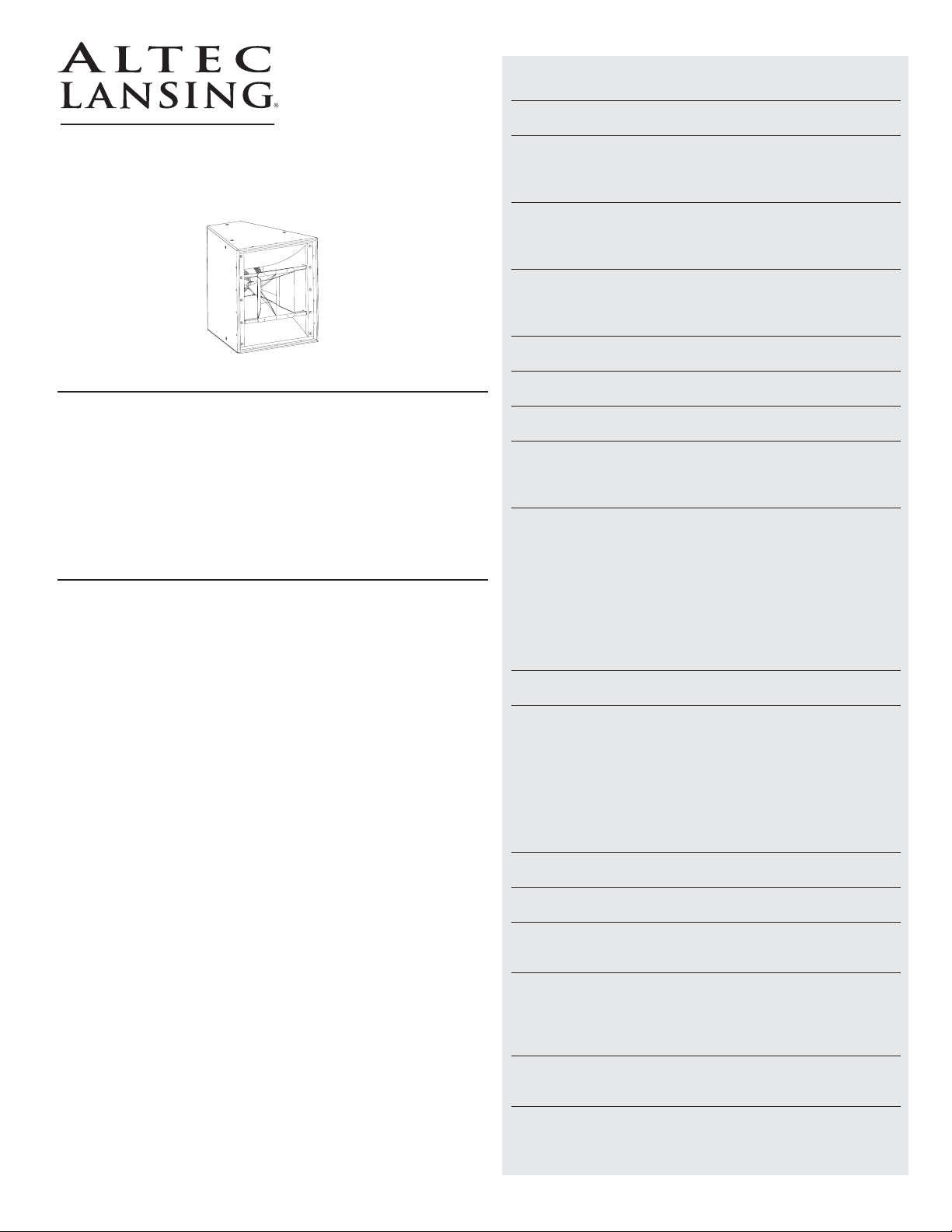
Altec Lansing’s new DE9412-8A two-way 12” Duplex®point-source
speaker system is designed to provide a high output solution for
reverberant spaces. The DE9412-8A is an excellent choice for
Auditoriums, Performing Arts Centers, Houses of Worship or any
application requiring high output reproduction of both music and speech
program material.
The DE9412-8A features Altec’s unique 12” Duplex®point-source speaker
component. This Duplex®“Engine” uses a single magnet structure, with
the high frequency diaphragm on the back of the magnet and the low
frequency voice coil and cone on the front of the structure. The result of
the proximity of the voice coils is a point-source alignment. Altec
Lansing’s use of this point-source Duplex®, or coaxial, design maximizes
speech intelligibility by minimizing the interference from adjacent
devices that so often occurs in traditional two-way speaker systems.
The 12” Duplex®“Engine” is installed in a bass horn cabinet. This
trapezoid enclosure provides predictable control in both the horizontal
and vertical planes to below 500 Hz (see polar charts, page 3). The use
of a bass horn cabinet insures that much of the low frequency energy is
kept off the performance area, even when the speakers are flown
overhead.
The DE9412-8A “Engine” is built around Altec’s large format 1.4” exit
throat high frequency compression driver, using a 2.8” Pascalite™
aluminum alloy diaphragm. The high frequency energy is fed from the
driver through the center of the magnet structure into a 90˚ x 40˚
Mantaray
®
high frequency horn. On the front of the magnet structure,
Altec uses a high efficiency 12” / 300mm cone woofer optimized for bass
horn enclosures.
The paintable trapezoid cabinet is constructed from strong 13-ply birch
plywood, with steel reinforced suspension points. Altec includes the
suspension hardware kit with each speaker. Color choices are charcoal
grey or white, with contrasting cloth covered metal grille. The DE94128A has an internal 1,000 Hz passive network that can be easily switched
over to bi-amp operation. Connectors are barrier strip or Neutrik
Speakon®connectors. Altec Lansing includes neutral grille cloth with each
subwoofer, allowing you to dye the cloth to integrate the subwoofer
into the surroundings.
For extended low frequency performance, the LF215-4A is a dual
15” / 380mm flyable subwoofer that has the same trapezoid footprint as
the DE9412-8A. Altec Lansing’s model 4048A 4-in x 8-out DSP processor
has available presets for a variety of design requirements.
™
High Frequency Horn
®
1000 W. Wilshire Blvd., Suite 362 • Oklahoma City, Oklahoma 73116 • Phone: 1-405-848-3108 • Fax: 1-405-848-3217 • www.altecpro.com
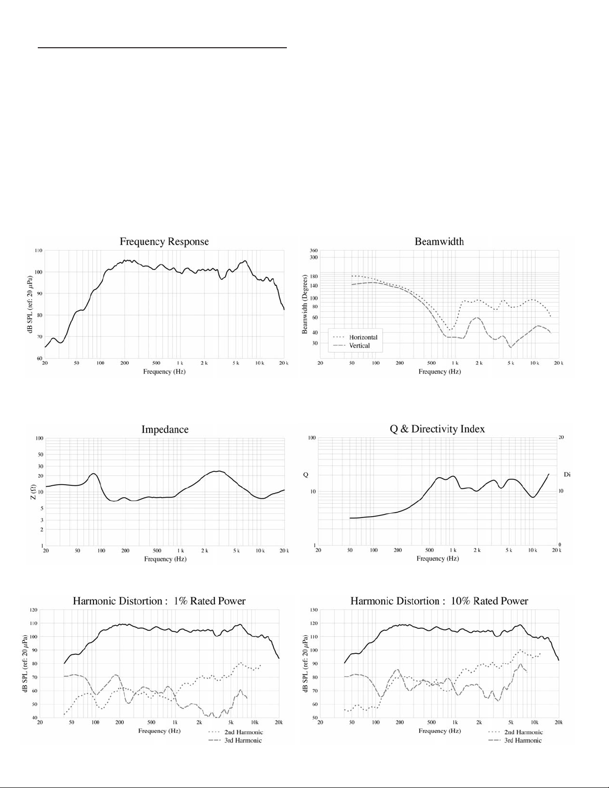
FREQUENCY RESPONSE
1, 2
110 Hz - 15 kHz (±3 dB)
USABLE LOW FREQUENCY LIMIT (-10 dB)
1, 2
85 Hz
SENSITIVITY
3
Full Range: 102 dB SPL
Low Frequency Section: 103 dB SPL, (2.83 V input)
High Frequency Section: 108 dB SPL, (2.83 V input)
POWER HANDLING
4
Full Range: 300 W continuous; 1,200 W peak
Low Frequency Section: 200 W continuous; 800 W peak
High Frequency Section: 75 W continuous; 300 W peak
MAXIMUM OUTPUT (1 m)
5
Full Range: 127 dB SPL continuous; 133 dB SPL peak
Low Frequency Section: 126 dB SPL continuous; 132 dB SPL peak
High Frequency Section: 127 dB SPL continuous; 133 dB SPL peak
COVERAGE ANGLES
6
90o (horizontal) x 40o (vertical)
DIRECTIVITY FACTOR, Q
6
13.97
DIRECTIVITY INDEX, Di
6
11.45 dB
TRANSDUCER COMPONENTS
LF: 1x 12 in. Woofer in a Sealed Mid-Bass Horn (E1012)
HF: 1x 1.4 in. Exit Compression Driver (E1012 on a
Constant Directivity Mantaray™Horn)
IMPEDANCE
7
Full Range:
Nominal: 8.0 Ω
Minimum: 6.6 Ω at 140 Hz
Low Frequency:
Nominal: 8.0 Ω
Minimum: 7.3 Ω at 290 Hz
High Frequency:
Nominal: 8.0 Ω
Minimum: 6.5 Ω at 3,500 Hz
CROSSOVER FREQUENCY
Passive LF - HF: 1,000 Hz
HARMONIC DISTORTION
8
1% rated power
2nd Harmonic 0.97%
3rd Harmonic 0.31%
THD 1.01%
10% rated power
2nd Harmonic 2.85%
3rd Harmonic 0.81%
THD 2.80%
INPUT CONNECTIONS
2x 4 position barrier strip and 2x NL4
CONTROLS
Lowpass On/Off and Highpass On/Off switches
ENCLOSURE MATERIALS & FINISH
18 mm, 13 ply Birch Plywood Finished with Charcoal Grey
or White Catalyzed Polyurethane
SUSPENSION SYSTEM
9
Working Load Limit (maximum weight applied to uppermost
mounting point): tbd lbs. (tbd kg)
(12) 3/8 in.-16 Threaded Mounting Suspension Points
(3 each top & bottom and 2 each sides & back)
DIMENSIONS
27.13 in. (H) x 24.13 in. (W) x 26.13 in. (D) x 10.13 in. (W rear)
689 mm (H) x 613 mm (W) x 664 mm (D) x 257 mm (W rear)
WEIGHT
Net 97 lbs. (44.1 kg)
Shipping 116 lbs. (52.7 kg)
Page 2
ARCHITECTS & ENGINEERS SPECIFICATION
The loudspeaker system shall be a two-way multi-purpose
type consisting of a 12 inch / 300mm Duplex
loudspeaker component featuring a 12” / 300mm low
frequency speaker combined in a single magnet structure
with a large format 1.4” exit throat high frequency
compression driver mated to a 90˚ x 40˚ Mantaray
frequency horn. The crossover network shall be a
dual-section, 12 dB / octave slope low pass and
12 dB / octave slope high pass with an electro-acoustic
crossover frequency of 1,000 Hz, switchable for bi-amp
operation. The loudspeaker system shall have an
operating bandwidth of 110 Hz - 15 kHz with a sensitivity
of 102 dB when measured at a distance of one meter. The
power handling capability shall be 300 W AES
(1,200 W peak). Nominal impedance shall be 8.0 ohms
®
point-source
™
high
with a minimum impedance of 6.6 ohms at 140 Hz. The
loudspeaker shall have nominal coverage angles of 90
degrees in the horizontal plane and 40 degrees in the
vertical plane. The paintable cabinet shall be a Sealed
Mid-Bass Horn, constructed of 18 mm Birch plywood
painted grey or white with a cloth covered metal grille.
The cabinet shall include integral suspension points.
Forged shoulder machinery eye bolts shall be included
to facilitate the suspension of the speaker system. The
dimensions shall be 27.13 inches (689 mm) high by 24.13
inches (613 mm) wide by 26.13 inches (664 mm) deep. The
loudspeaker system shall weigh 97 pounds (44.1 kg). The
loudspeaker system shall be the Altec Lansing Professional
model DE9412-8A.
Page 3

ONE-THIRD OCTAVE POLAR RESPONSE CHARTS
6 dB / DIVISION
Horizontal
Vertical
As we are continually striving to improve Altec Lansing products, specifications are subject to change without notice.
Please visit www.altecpro.com for the lastest information on Altec Lansing Professional products.
Page 4

MOUNTING DIMENSIONS
13.54 [343.83]
26.10 [663.05]
16.19 [411.26]
1.71 [43.40]
10.23 [259.78]
27.09 [688.00]
12.73 [323.28]
DENOTES CENTER OF MASS
DIMENSIONS SHOWN IN ( ) PARENTHESES ARE IN MILLIMETERS.
DIMENSIONS ARE IN INCHES.
26.10 [663.00]
10.10 [256.65]
5.05 [128.33]
16.64 [422.71]
7.56 [192.14]
24.10 [612.10]
1.71 [43.40]
11.87
12.73 [323.28]
6.65 [169.00]
15
SPECIFICATION NOTES
1 The frequency response of the loudspeaker system is measured at a distance of no less than 3 meters to obtain full range data. The level is
then corrected to be equivalent to a 2.83 V 1 m measurement. A near field measurement of the loudspeaker system is performed for
frequencies below 500 Hz. This data is then combined with the full range measurement to give an accurate composite frequency response
curve.
2 The limits of the frequency response are referenced to -3 dB of the systems rated sensitivity.
3 The sensitivity of the loudspeaker system is the log based average SPL taken over the intended bandwidth of operation for the system with a
2.83 V swept sine stimulus. The data is measured and level corrected in a manner consistent with note 1.
4 The power handling capacity of the loudspeaker system is tested using a full range form of AES Standard 2-1984. The test stimulus is band
limited (40 Hz – 16 kHz) pink noise with a 6 dB crest factor. The applied RMS voltage is determined using the minimum impedance of the
system. The amplifier used to drive the system has a minimum operating headroom of 6 dB referenced to the RMS voltage.
5 The maximum output level of the loudspeaker system is calculated based on the sensitivity and the power handling capabilities of the
system.
6 The coverage angles for the loudspeaker system are taken as the -6 dB points of the directivity response and averaged from 500 Hz – 16 kHz.
7 The minimum impedance of the loudspeaker system is taken over its intended band of operation.
8 The distortion measurements of the loudspeaker system are performed at a distance of 1 m with RMS input voltages corresponding to 1%
and 10% of rated system power handling calculated using minimum system impedance. The distortion percentages are log based averages
from 300 Hz – 3 kHz.
9 Before attempting to suspend the loudspeaker system, consult a certified structural engineer. This loudspeaker system can fall from
improper suspension, resulting in serious injury and property damage. Maximum enclosure rigging angle is 45°. Use only the correct mating
hardware, forged shoulder machinery eye bolt, Mil Spec MIL 51937-3. All associated rigging is the responsibility of others.
VISIT WWW.ALTECPRO.COM FOR
• Authorized EASE®data on Altec Lansing Professional speakers.
• Specification sheets in .pdf format. Download page 1 of the specification sheet for your submittals.
• One paragraph A & E Specifications in .doc format.
AW1141 REV01
P ROFESSIONAl
© 2003 Altec Lansing Professional
1000 W. Wilshire Blvd., Suite 362
Oklahoma City, Oklahoma 73116
Phone: 1-405-848-3108 • Fax: 1-405-848-3217
Web: www.altecpro.com • Email: proinfo@alteclansing.com
 Loading...