

Page 1
Vehiclehub Pro
R
VPA-B222
• OWNER'S MANUAL
Please read before using this equipment.
• MODE D'EMPLOI
Veuillez lire avant d’utiliser cet appareil.
• MANUAL DE OPERACIÓN
Léalo antes de utilizar este equipo.
R
EN
FR
ES
ALPINE ELECTRONICS MARKETING, INC.
1-1-8 Nishi Gotanda,
Shinagawa-ku,
Tokyo 141-0031, Japan
Phone 03-5496-8231
ALPINE ELECTRONICS OF AMERICA, INC.
19145 Gramercy Place, Torrance,
California 90501, U.S.A.
Phone 1-800-ALPINE-1 (1-800-257-4631)
ALPINE ELECTRONICS OF CANADA, INC.
777 Supertest Road, Toronto,
Ontario M3J 2M9, Canada
Phone 1-800-ALPINE-1 (1-800-257-4631)
YAMAGATA Corporation
2-6-34, Takashima, Nishi-ku,
Yokohama, Kanagawa, Japan
ALPINE ELECTRONICS OF AUSTRALIA PTY. LTD.
161-165 Princes Highway, Hallam
Victoria 3803, Australia
Phone 03-8787-1200
ALPINE ELECTRONICS GmbH
Frankfurter Ring 117, 80807 München, Germany
Fletchamstead Highway, Coventry CV4 9TW, U.K.
B.P. 50016, 95945 Roissy Charles de Gaulle
Phone 089-32 42 640
ALPINE ELECTRONICS OF U.K. LTD.
Alpine House
Phone 0870-33 33 763
ALPINE ELECTRONICS FRANCE S.A.R.L.
(RCS PONTOISE B 338 101 280)
98, Rue de la Belle Etoile, Z.I. Paris Nord Il,
Cedex, France
Phone 01-48638989
ALPINE ITALIA S.p.A.
Viale C. Colombo 8, 20090 Trezzano
Sul Naviglio (MI), Italy
Phone 02-484781
ALPINE ELECTRONICS DE ESPAÑA, S.A.
Portal de Gamarra 36, Pabellón, 32
01013 Vitoria (Alava)-APDO 133, Spain
Phone 945-283588
ALPINE ELECTRONICS (BENELUX) GmbH
Leuvensesteenweg 510-B6,
1930 Zaventem, Belgium
Phone 02-725-13 15
Designed by ALPINE Japan
Printed in Japan (Y)
68-02065Z86-A
Page 2
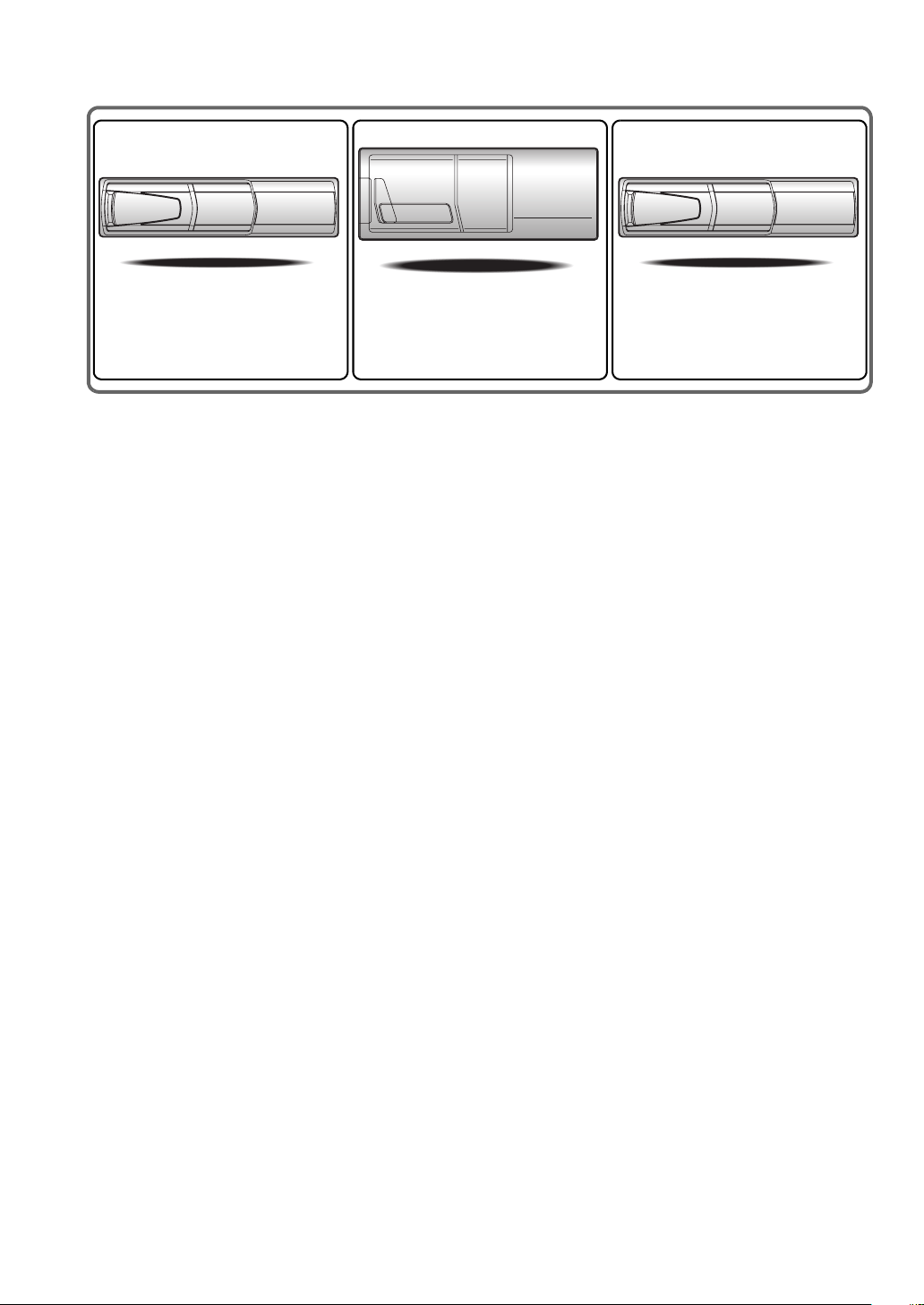
CHA-S634
• CD changer for VPA-B222.
• Changeur CD pour VPA-B222.
• Cambiador de CD para VPA-B222.
CHA-1214
• CD changer for VPA-B222.
• Changeur CD pour VPA-B222.
• Cambiador de CD para VPA-B222.
CHM-S630
Alpine CD Changers Give You More!
More musical selections, more versatility, more convenience.
The CHA-S634 is a high-performance 6-disc changer with a new M DAC, CD-R/RW PLAY BACK, MP3 PLAY BACK and CD TEXT.
The CHA-1214 Ai-NET model holds 12 discs, and the CHM-S630 M-Bus model is a super-compact 6-disc changer with a CD-R/RW
PLAY BACK.
Changeurs de CD Alpine : vous avez le choix!
Plus de sélections musicales, plus de souplesse, plus de confort.
Le modèle CHA-S634 est un changeur 6 disques ultra performant équipé des nouvelles fonctions M DAC, CD-R/RW PLAY BACK, MP3
PLAY BACK et CD TEXT. Le modèle CHA-1214 Ai-NET contient 12 disques. Le modèle CHM-S630 M-Bus est un changeur 6 disques
super compact doté de la fonction CD-R/RW PLAY BACK.
¡Los cambiadores Alpine de CD le ofrecen más!
Más selecciones musicales, más versatilidad y más ventajas.
CHA-S634 es un cambiador de seis discos de alto rendimiento con nuevo M DAC, CD-R/RW PLAY BACK, MP3 PLAY BACK y CD
TEXT. El modelo CHA-1214 Ai-NET alberga 12 discos y el modelo CHM-S630 M-Bus es un cambiador de seis discos de tamaño
reducido con un CD-R/RW PLAY BACK.
Page 3

ENGLISH
Contents
Operating Instructions
WARNING
WARNING ................................................. 4
CAUTION .................................................. 4
PRECAUTIONS ........................................ 5
Getting Started
Feature .............................................................. 6
Accessory List .................................................. 6
Initial System Start-Up ..................................... 6
Turning Power On or Off ................................. 6
Displaying the Unit Source on the
Monitor ...................................................... 6
Switching a Source ........................................... 7
Adjusting the Volume ....................................... 7
Lowering Volume Quickly ............................... 7
Radio
Listening to Radio ............................................ 7
Manual Storing of Station Presets .................... 8
Automatic Memory of Station Presets ............. 8
Tuning to Preset Stations .................................. 8
Setting Analog Mode
(HD Radio mode only) ................................. 8
Changing the Display
(HD Radio mode only) ................................. 9
Other Useful Features
Adjusting the Audio ......................................... 9
Adjusting the Balance ................................. 10
Adjusting the Fader ..................................... 10
Setting the Treble Control ........................... 10
Setting the Bass Control ............................. 10
Adjusting the Subwoofer Level .................. 10
Tuning Loudness ON or OFF ..................... 10
Tuning Defeat ON or OFF ........................... 10
Adjusting Volume of GUIDE Voice ............10
Rear Entertainment Function ..........................11
Switching the function of the remote
sensor .......................................................11
Setup
GENERAL Setup
General Setup Operation .................................12
Demonstration Function .............................. 12
Setting the Time Display .............................12
Setting the Time ...........................................13
Setting Daylight Saving Time .....................13
Sound (Beep) Guide Function .....................13
Turning the Commander Vibration
ON or OFF ...............................................13
Setting the Scroll .........................................13
SYSTEM Setup
System Setup Operation ..................................13
Using the Speaker Input ..................................14
Setting the Speaker Input Mode .................. 14
Displaying the Speaker Input Volume
Level .........................................................14
Setting the Navigation/Speaker Input Voice
Interruption ...............................................14
Adjusting the Speaker Input's Interruption
Detection Level ........................................14
Adjusting the Speaker Input Voice Interruption
Level .........................................................14
Setting the Interrupt Type of the Speaker Input
Voice .........................................................15
Setting the Channel of the Speaker Interruption
Detection ..................................................15
Connecting the Navigation ............................. 15
Setting the Navigation Mode .......................15
Navigation Audio Interruption Volume
Adjustment ...............................................15
Connecting an External Input Device
(AUX) ..........................................................15
Setting the AUX Mode ................................15
Naming External Devices ............................15
1-EN
Page 4

Adjusting the External Input Audio
Level ........................................................15
Connecting the Rear Monitor .........................16
Setting of the External Monitor Output ...... 16
Setting the VISUALIZER Mode Display ... 16
Connecting a Subwoofer ................................ 16
Subwoofer On and Off ................................ 16
Setting the Commander .................................. 16
Setting the Color of the Commander Button
illumination .............................................. 16
Turning the Commander Button illumination
on and off .................................................16
Adjusting the Brightness of the Commander
Button illumination .................................. 16
Setting the Others ...........................................16
Setting the External Device Interrupt
Mode ........................................................16
Adjusting the display position ..................... 17
Setting the Auxiliary Data Field Display .... 17
Switching the Subtitles (Subtitle Language)
(DVD only) ................................................. 22
Switching the Angle (DVD only) ................... 22
Switching from the disc menu .................... 22
SAT Radio Receiver (Optional)
Receiving Channels with the SAT Receiver ... 23
Tuning in to Categorized Programs ................ 23
Changing the Display ..................................... 23
Checking the SAT Radio ID Number ............. 24
Storing Channel Presets ................................. 24
Receiving Stored Channels ............................ 24
Category/Channel Search Function ................ 25
Storing Weather or Traffic information from SAT
Radio ........................................................... 25
Receiving Weather or Traffic Information from
SAT Radio ................................................... 25
CD/MP3/WMA Operation (Optional)
Playing CD/MP3/WMA .................................17
Folder/File Search ........................................... 18
M.I.X. (Random Play) .................................... 18
Repeat Play .....................................................18
DVD/Video CD Operation (Optional)
Playing DVD/Video CD ................................. 19
To display the DVD mode screen ................ 20
If a menu screen appears ............................. 20
Playing Still Frames (Pausing) ....................... 20
Finding the Beginnings of Chapters or
Tracks ..........................................................20
Fast-forwarding/Fast-reversing ....................... 20
Displaying the Top Menu Screen
(DVD only) .................................................. 21
Changing Discs (only when DVD changer is
connected) ...................................................21
Stopping Playback (PRE STOP) .................... 21
Stopping Playback .......................................... 21
Chapter/Track/Title Repeat Playback ............. 21
Switching the Audio Tracks ........................... 21
iPod® (Optional)
Playback ......................................................... 25
Searching for a desired Song .......................... 26
Searching by Playlist .................................. 26
Searching by artist name ............................. 26
Searching by album name ........................... 26
Searching by Song Name ............................ 27
Select Playlist/Artist/Album ........................... 27
Random Play Shuffle (M.I.X.) .................... 27
Repeat Play ..................................................... 27
Navigation System (Optional)
Displaying the Navigation Screen .................. 28
Changing the Navigation operation mode ...... 28
Map Screen Function ..................................... 28
Displaying the Current Position .................. 28
Scrolling the Map ........................................ 28
Changing the Map Scale ............................. 28
Menu Screen Function ................................... 28
TV Operation (Optional)
Operating TV Unit ......................................... 29
Automatic Memory of Channel Presets ......... 29
2-EN
Page 5

Switching Audio ............................................. 29
Auxiliary Device (Optional)
Operating Auxiliary Devices (Optional) ........ 30
Factory System
Operating Factory System
(Speaker Input mode) .................................. 31
HDD Player Operation (Optional)
Listening to Music of HDD ............................ 31
External Audio Processor (Optional)
Adjustment Procedure for Dolby Surround ... 32
Setting the Speakers ....................................... 33
Set MX Mode of the External Audio
Processor ..................................................... 33
X-OVER Adjustment ..................................... 33
Performing Time Correction Manually
(TCR) .......................................................... 34
Phase Switching ............................................. 35
Graphic Equalizer Adjustments ..................... 35
Parametric Equalizer Adjustments ................. 35
Setting Bass Sound Control ........................... 36
Setting Bass Compressor ............................ 36
Setting Bass Focus ...................................... 36
Speaker Setup ................................................. 36
Setting of Dolby Digital ................................. 37
Adjusting the acoustic image ...................... 37
Mixing bass sound to the rear channel ........ 37
Achieving powerful high volume sound ..... 37
Adjusting the speaker levels ....................... 37
Adjusting the DVD Level ............................... 38
Storing Settings in the Memory ..................... 38
Calling up the Preset Memory ........................ 38
Using the Pro Logic II Mode ......................... 38
Linear PCM Setting ........................................ 39
Soft button operation
Basic operation ...............................................39
Radio Operation ..............................................40
Setup Operation ..............................................40
CD/MP3/WMA Operation ..............................41
DVD/Video CD Operation ..............................41
SAT Radio Operation ...................................... 42
®
iPod
Operation ..............................................43
TV Operation ..................................................44
HDD Player Operation ....................................44
Information
In Case of Difficulty .......................................45
Specifications ..................................................47
Installation and
Connections
Warning .................................................. 48
Caution ................................................... 48
Precautions ........................................... 48
Installation ......................................................49
Connections (VPA-B222 Wiring Diagram) .... 52
System Example ............................................. 54
LIMITED WARRANTY
3-EN
Page 6
Operating Instructions
DO NOT BLOCK VENTS OR RADIATOR PANELS.
WARNING
WARNING
This symbol means important instructions.
Failure to heed them can result in serious injury
or death.
INSTALL THE PRODUCT CORRECTLY SO THAT THE DRIVER
CANNOT WATCH TV/VIDEO UNLESS THE VEHICLE IS
STOPPED AND THE EMERGENCY BRAKE IS APPLIED.
It is dangerous (and illegal in many states) for the driver to watch
TV/Video while driving a vehicle. Installing this product
incorrectly enables the driver to watch TV/Video while driving.
This may cause a distraction, preventing the driver from looking
ahead, thus causing an accident. The driver or other people could be
severely injured.
DO NOT WATCH VIDEO WHILE DRIVING.
Watching the video may distract the driver from looking ahead of
the vehicle and cause an accident.
Doing so may cause heat to build up inside and may result in fire.
USE THIS PRODUCT FOR MOBILE 12V APPLICATIONS.
Use for other than its designed application may result in fire,
electric shock or other injury.
This symbol means important instructions.
Failure to heed them can result in injury or
material property damage.
HALT USE IMMEDIATELY IF A PROBLEM APPEARS.
Failure to do so may cause personal injury or damage to the
product. Return it to your authorized Alpine dealer or the nearest
Alpine Service Center for repairing.
CAUTION
DO NOT OPERATE ANY FUNCTION THAT TAKES YOUR
ATTENTION AWAY FROM SAFELY DRIVING YOUR VEHICLE.
Any function that requires your prolonged attention should only be
performed after coming to a complete stop. Always stop the vehicle
in a safe location before performing these functions. Failure to do
so may result in an accident.
KEEP THE VOLUME AT A LEVEL WHERE YOU CAN STILL
HEAR OUTSIDE NOISE WHILE DRIVING.
Failure to do so may result in an accident.
MINIMIZE DISPLAY VIEWING WHILE DRIVING.
Viewing the display may distract the driver from looking ahead of
the vehicle and cause an accident.
DO NOT DISASSEMBLE OR ALTER.
Doing so may result in an accident, fire or electric shock.
USE ONLY IN CARS WITH A 12 VOLT NEGATIVE GROUND.
(Check with your dealer if you are not sure.) Failure to do so may
result in fire, etc.
KEEP SMALL OBJECTS SUCH AS BATTERIES OUT OF THE
REACH OF CHILDREN.
Swallowing them may result in serious injury. If swallowed,
consult a physician immediately.
USE THE CORRECT AMPERE RATING WHEN REPLACING
FUSES.
Failure to do so may result in fire or electric shock.
4-EN
Page 7
PRECAUTIONS
Product Cleaning
Use a soft dry cloth for periodic cleaning of the product. For more
severe stains, please dampen the cloth with water only. Anything
else has the chance of dissolving the paint or damaging the plastic.
Temperature
Be sure the temperature inside the vehicle is between +45°C
(+113°F) and 0°C (+32°F) before turning your unit on.
Moisture Condensation
You may notice the disc playback sound wavering due to
condensation. If this happens, remove the disc from the player and
wait about an hour for the moisture to evaporate.
Maintenance
If you have problems, do not attempt to repair the unit yourself.
Return it to your Alpine dealer or the nearest Alpine Service
Station for servicing.
Installation Location
Make sure the VPA-B222 will not be installed in a location
subjected to:
• Direct sun and heat
• High humidity and water
• Excessive dust
• Excessive vibrations
Alpine products equipped with the Ai-NET bus, connected to the
VPA-B222, can be operated from the VPA-B222. Depending on the
products connected, the functions and displays will vary. For
details, consult your Alpine dealer.
Operation of some of the functions of this unit is very complex.
Because of this, it was deemed necessary to place these functions
into a special screen. This will restrict operation of these functions
to times when the vehicle is parked. This ensures the focus of the
driver’s attention will be on the road and not on the VPA-B222.
This has been done for the safety of the driver and passengers.
Audio Processor Adjustments cannot be made if the car is moving.
The car must be parked and the parking brake must be engaged for
the procedure described in the Owner’s Manual to be valid. The
warning “CAN’T OPERATE WHILE DRIVING,” will be
displayed if any attempts are made to perform these operations
while driving.
• Apple, the Apple logo and iPod are trademarks of Apple
Computer, Inc., registered in the U.S. and other countries.
• HD Radio™ Technology Manufactured Under License From
iBiquity Digital Corporation. iBiquity Digital and the HD
Radio and HD Symbols are trademarks of iBiquity Digital
Corporation. U.S. and Foreign Patents.
5-EN
Page 8
Getting Started
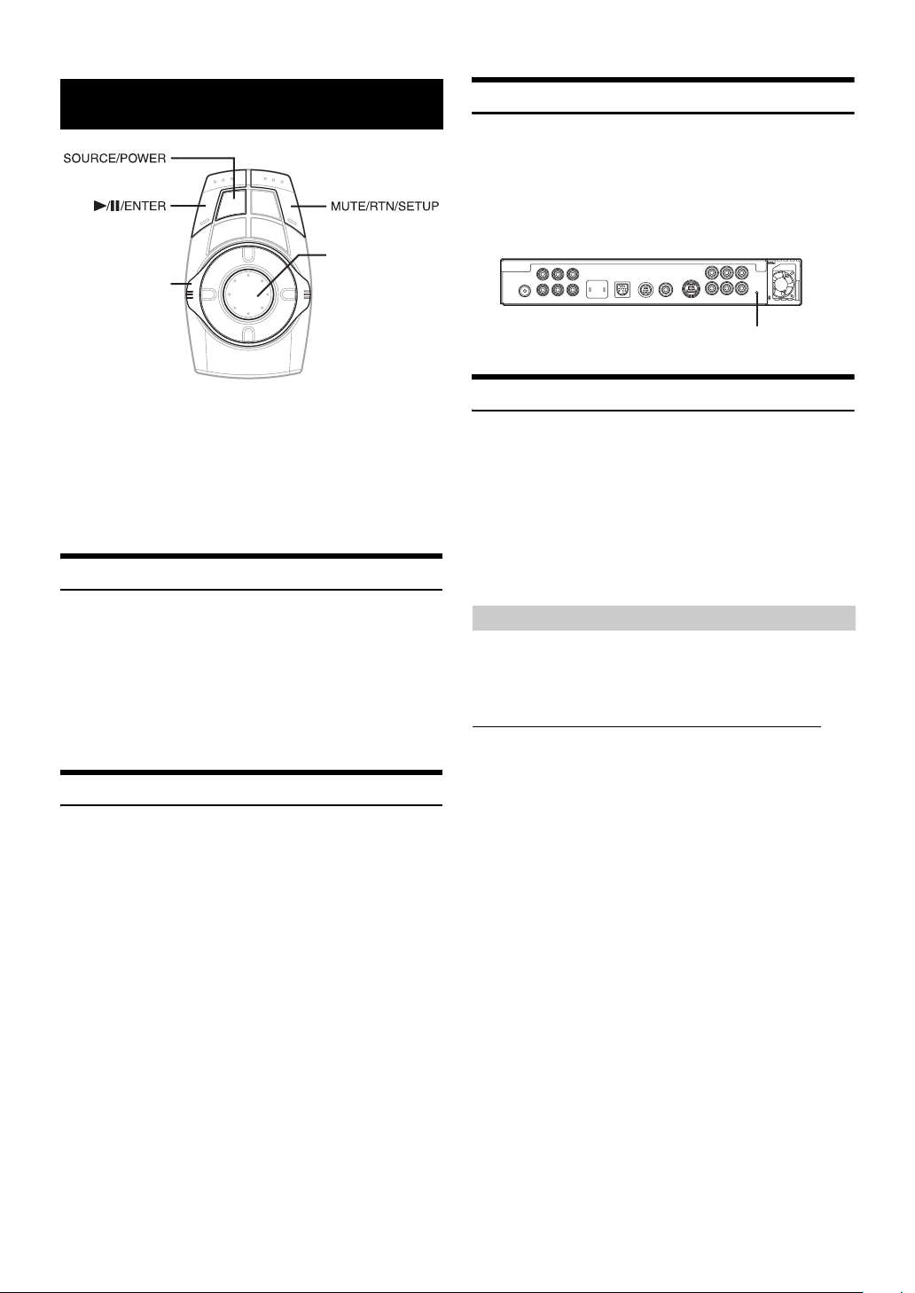
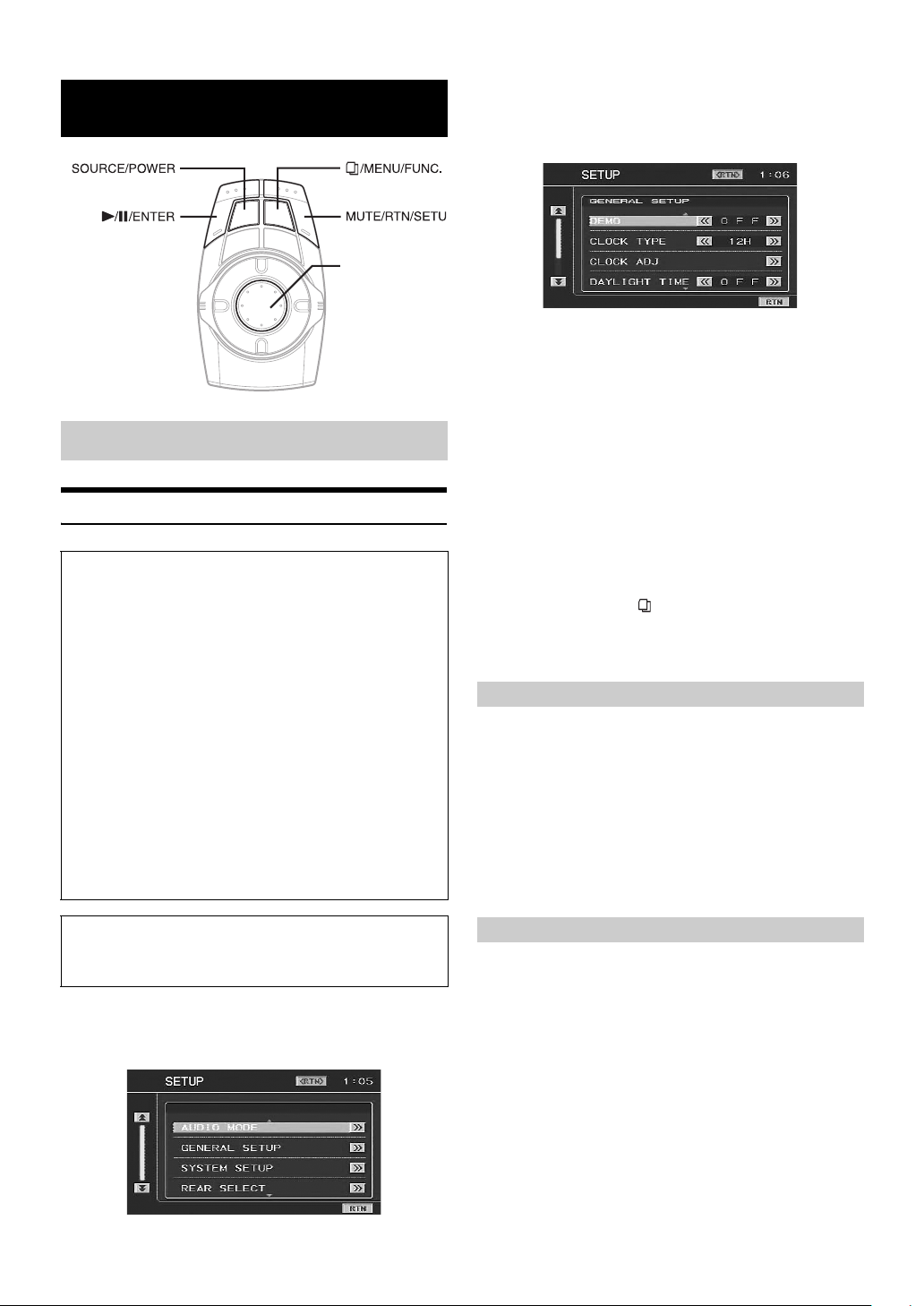
Joystick
Flipper switch
Initial System Start-Up
Be sure to press the RESET button when using the unit for the first time,
after installing the CD changer, after changing the car battery, etc.
1
Turn off the unit power.
2
Press RESET with a ball-point pen or similar
pointed object.
RESET
Operation is carried out by the commander. If an Alpine touch panel
monitor is connected to this unit, the touch buttons appear in the display
to enable touch operation.
This manual explains operation using the commander. For details of the
touch operation, refer to “Soft button operation” on page 39.
• The commander vibrates when an operation is performed. Refer to
“Turning the Commander Vibration ON or OFF” (page 13).
Feature
If an Alpine Ai-NET compatible products (DVD player, DVD/CD
changer), or iPod using the FULLSPEED™ Connection Cable is
connected to the VPA-B222, it can be controlled from the commander
and displayed on the external monitor. If an optional Alpine Navigation
System is connected to the VPA-B222, the Navigation screen will be
displayed on the external monitor, and its operation can be performed.
For details on the function of connected devices, refer to the Owner’s
Manual.
Accessory List
Main unit....................................................................................1
Power cable...............................................................................1
Parking brake sub-lead .............................................................1
Factory System Cable...............................................................1
Pinch connector ........................................................................6
Bracket......................................................................................2
Tapping screw (M4 × 14)...........................................................4
Pan screw (M4 × 8) ...................................................................4
Velcro fastener ..........................................................................2
RGB cable (3M) ........................................................................1
RCA extension cable (3M) ........................................................1
Antenna extension cable (3M)...................................................1
Commander ..............................................................................1
Holder........................................................................................1
Commander connection cable (3M) ..........................................1
Double-sided adhesive tape ......................................................1
Reinforcement screw.................................................................3
Cable clamp ..............................................................................3
Turning Power On or Off
Some of this unit’s functions cannot be performed while the vehicle is in
motion. Be sure to stop your vehicle in a safe location and apply the
parking brake, before attempting these operations.
1
Press SOURCE/POWER to turn on the unit.
• The unit can be turned on by pressing any button.
2
Press and hold SOURCE/POWER for at least 2
seconds to turn off the unit.
Displaying the Unit Source on the Monitor
By selecting the image source on the unit, it can be displayed on a
connected monitor. For operation, refer to the Owner’s Manual of the
monitor.
If an Alpine monitor is connected (RGB connection)
1 Recall the navigation mode by selecting the image
source on the monitor.
The source of the unit is displayed.
6-EN
Page 9
Switching a Source
1
Press SOURCE/POWER.
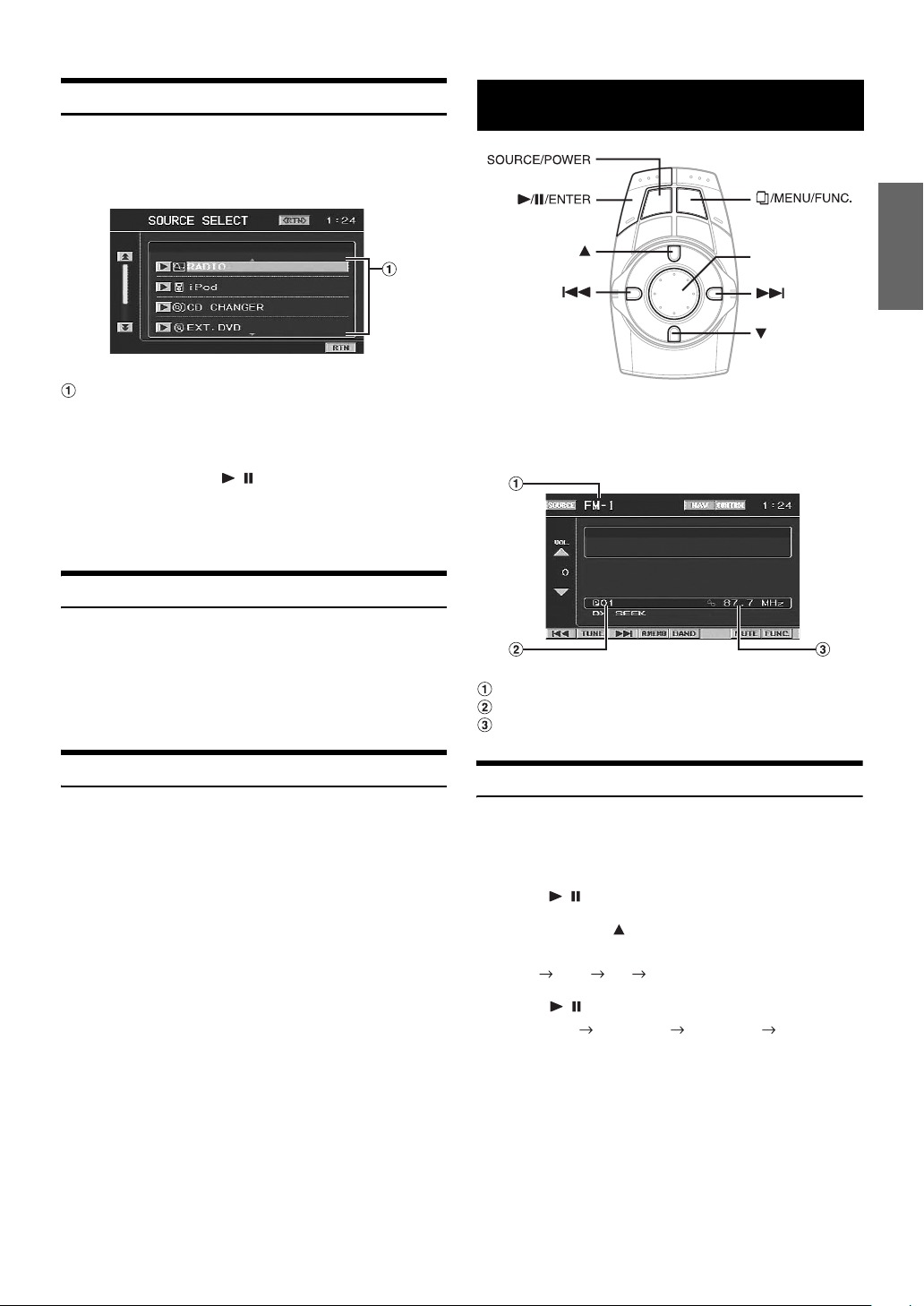
The source selection screen is displayed.
Screen example
Radio
Joystick
Displays source modes that can be selected
(The kind of source modes that are displayed varies
depending on connection and setting)
2
Press the joystick up or down to select the desired
source, then press / /ENTER.
The selected main source screen is displayed.
• In the source selection screen mode, press MUTE/RTN/SETUP to
return to the previous screen.
Adjusting the Volume
Turn th e flipper switch clockwise or counterclockwise
to adjust the volume.
Clockwise: Volume up
Counterclockwise: Volume down
Volume: 0 - 35
Lowering Volume Quickly
Activating this function will instantly lower the volume level.
Press MUTE/RTN/SETUP to activate the MUTE mode.
The audio level decreases.
During mute, the volume level indicator will blink.
Pressing MUTE/RTN/SETUP again brings the audio back to its
previous level.
This unit cannot receive HD Radio™ signals (digital terrestrial radio).
In order to activate the digital radio functions described below, an
optional HD Radio Tuner module must be connected through the
Ai-NET bus.
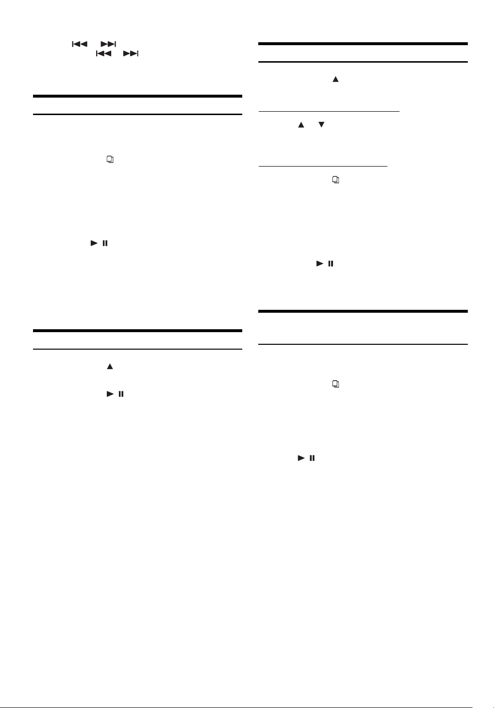
Band display
Preset number display
Frequency display
Listening to Radio
1
Press SOURCE/POWER.
The source selection screen is displayed.
2
Press the joystick up or down to select RADIO, then
press / /ENTER.
3
Press and hold for at least 2 seconds repeatedly
until the desired radio band is displayed.
FM-1 FM-2 AM FM-1
4
Press / /ENTER to select the tuning mode.
DX SEEK SEEK (OFF) DX SEEK
• The initial mode is Distance mode.
DX SEEK (Distance mode):
Both strong and weak stations will be automatically tuned in
(Automatic Seek Tuning).
SEEK (Local mode):
Only strong stations will be automatically tuned in (Automatic
Seek Tuning).
OFF (Manual mode):
The frequency is manually tuned in steps (Manual tuning).
7-EN
Page 10
5
Press or to tune in the desired station.
Holding down or will change the frequency
continuously.
• “DIGITAL” is displayed when a digital radio station is received.
Tuning to Preset Stations
1
Press and hold for at least 2 seconds repeatedly
until the desired band is displayed.
Manual Storing of Station Presets
1
Select the radio band and tune in a desired radio
station you wish to store in the preset memory.
2
Press and hold /MENU/FUNC. for at least 2
seconds.
The FUNCTION screen is displayed.
3
Press the joystick up or down to select PRESET
MEMORY, then press the joystick right.
4
Press the joystick up or down to select any one of
the preset numbers PRESET1 through PRESET6,
then press / /ENTER.
The selected station is stored.
The display shows the band, preset number and station
frequency memorized.
• A total of 18 stations can be stored in the preset memory (6 stations
for each band; FM-1, FM-2 and AM).
• If you store a station in a preset memory which already has a station,
the current station will be cleared and replaced with the new station.
Automatic Memory of Station Presets
1
Press and hold for at least 2 seconds repeatedly
until the desired radio band is displayed.
2
Press and hold / /ENTER for at least 2 seconds.
The frequency on the display continues to change while the
automatic memory is in progress. The tuner will
automatically seek and store 6 strong stations in the
selected band. They will be stored into PRESET1 to
PRESET6 in order of signal strength.
When the automatic memory has been completed, the tuner
goes to the station stored in preset location No. 1.
• If no stations are stored, the tuner will return to the original station
you were listening to before the auto memory procedure began.
Changing Stations by the Commander
2
Press or to select a preset number (P01 to
P06).
The selected station is received.
Recalling by the FUNCTION screen
2
Press and hold /MENU/FUNC. for at least 2
seconds.
The FUNCTION screen is displayed.
3
Press the joystick up or down to select PRESET
CALL, then press the joystick right.
4
Press the joystick up or down to select any one of
the preset numbers PRESET1 through PRESET6,
then press / /ENTER.
The preset station is received.
The display shows the band, preset number and frequency
of the station selected.
Setting Analog Mode (HD Radio mode
only)
While receiving HD radio, you can switch to analog signal mode, even
in areas that receive digital radio station signals.
1
Press and hold /MENU/FUNC. for at least 2
seconds.
The FUNCTION screen is displayed.
2
Press the joystick up or down to select ANALOG
MODE, then press the joystick right.
3
Press the joystick up or down to select ON, then
press / /ENTER.
8-EN
Page 11

Changing the Display (HD Radio mode
only)
Other Useful
Text information, such as Station name, Song title, Artist, etc., is
displayed while receiving a digital radio station.
1
Press and hold /MENU/FUNC. for at least 2
seconds.
The FUNCTION screen is displayed.
2
Press the joystick up or down to select the INFO.,
then press / /ENTER.
Each time you perform the above operations, the display
changes as shown below.
Short Station Name *
Song title *
Artist *
Album *
*1Displays Short Station Name / Long Station Name in the Station
Information Service Data.
*2Displays Song title / Artist / Album in the main program Service
Data.
2
2
2
1
Long Station Name *
Features
1
Adjusting the Audio
The following steps 1 to 5 are common operations of each audio
adjustment. Refer to each section for details.
1
Press and hold MUTE/RTN/SETUP for at least 2
seconds.
The SETUP screen is displayed.
2
Press the joystick up or down to select AUDIO
MODE, then press the joystick right.
The AUDIO MODE screen is displayed.
Display Example for Audio MODE Screen
Joystick
3
Press the joystick up or down to select the desired
item.
Setting items: BALANCE / FADER / TREBLE / BASS /
* Setting can be made only when an external audio processor is
connected.
4
Press the joystick left or right to adjust and set the
desired item.
5
Press MUTE/RTN/SETUP to return to the previous
screen. Press MUTE/RTN/SETUP repeatedly to
return to the main source screen displayed before
starting the setup operation.
SUBW LEVEL / LOUDNESS / DEFEAT /
GUIDE MIX LV*
9-EN
Page 12

Adjusting the Balance
Adjust the sound volume of the left and right speakers.
Setting item: BALANCE
Setting range: L15 to R15
Adjusting the Fader
Adjust the volume of the front and rear speakers.
Setting item: FADER
Setting range: F15 to R15
Setting the Treble Control
You can change the Treble Frequency emphasis to create your own tonal
preference.
1
Select TREBLE on the AUDIO MODE screen, then
press the joystick right.
2
Press the joystick up or down to select the desired
item, then press the joystick left or right to adjust
and set the desired item.
Setting the treble level
You can boost or cut treble frequencies.
(The level of each audio source can be adjusted.)
Setting item: LEVEL
Setting level: -7 to +7
Setting the treble center frequency
The displayed treble frequency is boosted.
(Common to each audio source.)
Setting item: FREQUENCY
Setting range: 7.5kHz 10kHz 12.5kHz 15kHz
• Adjustment cannot be performed when an external audio processor is
connected and DEFEAT is set to ON.
Setting the Bass Control
You can change the Bass Frequency emphasis to create your own tonal
preference.
1
Select BASS on the AUDIO MODE screen, then
press the joystick right.
Setting the bass center frequency
The displayed bass frequency is boosted.
(Common to each audio source.)
Setting item: FREQUENCY
Setting range: 60Hz 80Hz 100Hz 120Hz
• Adjustment cannot be performed when an external audio processor is
connected and DEFEAT is set to ON.
Adjusting the Subwoofer Level
Adjust the subwoofer output.
Setting item: SUBW LEVEL
Setting range: 0 to 15
• The level adjustment becomes available when ON is set in
“Subwoofer On and Off” (page 16).
Tuning Loudness ON or OFF
Loudness introduces a special low- and high-frequency emphasis at low
listening levels. This compensates for the ear's decreased sensitivity to
bass and treble sound.
Setting item: LOUDNESS
Setting range: ON / OFF
• Adjustment cannot be performed when an external audio processor is
connected and DEFEAT is set to ON.
Tuning Defeat ON or OFF
By setting Defeat ON, previously adjusted settings of BASS and
TREBLE will return to the factory defaults.
Setting item: DEFEAT
Setting range: ON / OFF
Adjusting Volume of GUIDE Voice
The volume level of the speaker input voice and the navigation interrupt
voice output from the external audio processor is adjusted.
Setting item: GUIDE MIX LV
* Setting range: 0 to 15
* Make sure to adjust this setting to 15. Otherwise operation may not
be correctly performed.
• Adjust the speaker input voice interruption level in “Adjusting the
Speaker Input Voice Interruption Level” (page 14) and “Navigation
Audio Interruption Volume Adjustment” (page 15).
2
Press the joystick up or down to select the desired
item, then press the joystick left or right to adjust
and set the desired item.
Setting the bass level
You can boost or cut bass frequencies.
(The audio source level can be adjusted.)
Setting item: LEVEL
Setting level: -7 to +10
Setting the slope
Select the frequency you want to set within the available range.
(Common to each audio source.)
Setting item: SLOPE
Setting range: 0.50 0.75 1.00 1.25
10-EN
Page 13
Rear Entertainment Function
The rear entertainment function independently routes different sources
to the front and the rear inside a car. For example, while listening to the
radio or other audio source in the front, DVD can be enjoyed in the rear
with the optional rear monitor and headphones.
To connect the rear monitor, the optional expansion box VPE-S431 is
required.
1
Press and hold MUTE/RTN/SETUP for at least 2
seconds.
The SETUP screen is displayed.
2
Press the joystick up or down to select REAR
SELECT, then press the joystick right.
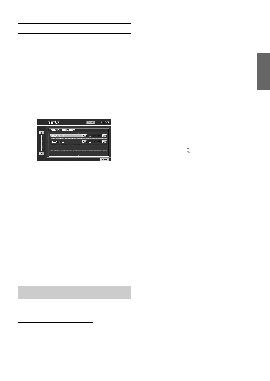
The REAR SELECT screen is displayed.
Display Example for REAR SELECT screen
• This function cannot be used when MONITOR-1 or 2 is set to
OFF in SYSTEM SETUP.
3
Press the joystick up or down to select the desired
external monitor.
REAR-1: A rear external monitor can be connected to AUX
REAR-2: A rear external monitor can be connected to AUX
OUT 1 of the optional expansion box (VPE-S431).
OUT 2 of the optional expansion box (VPE-S431)
3
Press the joystick left or right to select the monitor
to be controlled by the remote control.
FRONT: Remote control operation can be performed
REAR-1: The remote sensor of the external monitor
REAR-2: The remote sensor of the external monitor
4
Press MUTE/RTN/SETUP to return to the previous
screen. Press MUTE/RTN/SETUP repeatedly to
return to the main source screen displayed before
starting the setup operation.
• Select SETUP on the FUNCTION screen to recall the SETUP screen
after pressing and holding /MENU/FUNC. for at least 2 seconds.
• The sensor of the touch panel rear monitor has priority over the
sensor of the remote control, if the rear monitor (connected to the
Alpine touch panel rear monitor via the Monitor control lead) is
touched, regardless of the remote control sensor switch setting. Note,
however, that the sensor of the remote control that has been set takes
priority if it has been 5 seconds since last touching the panel.
when the Alpine monitor is connected using an
RGB cable, and also when a monitor (other
than Alpine) connected to a remote control
sensor unit (optional) is connected.
connected to AUX OUT1 of the tuner box of this
unit, or the optional expansion box (VPE-S431)
is effective, and the remote control can operate
only the source selected for the REAR SELECT
screen.
connected to AUX OUT2 of the optional
expansion box (VPE-S431) is effective, and the
remote control can operate only the source
selected for the REAR SELECT screen.
4
Press the joystick left or right to set the desired
video source (external input).
5
Press MUTE/RTN/SETUP to return to the previous
screen. Press MUTE/RTN/SETUP repeatedly to
return to the main source screen displayed before
starting the setup operation.
• To cancel the rear entertainment function, set to OFF.
• When the “Setting the AUX Mode” (page 15) is set to OFF, the
auxiliary source is not displayed.
• VISUALIZER (VISUAL.) is not displayed when the setting of “Setting
the VISUALIZER Mode Display” (page 16) is turned off.
Switching the function of the remote
sensor
For remote control operation, the remote sensor of the external device
(monitor, etc.) can be switched, as you prefer.
Switching the Remote Control Sensor
1
In the SETUP screen mode, press the joystick up or
down to select SYSTEM SETUP, then press the
joystick right.
The SYSTEM SETUP screen is displayed.
2
Press the joystick up or down to select REMOTE
SEL.
11-EN
Page 14
Setup
Joystick
GENERAL Setup
General Setup Operation
To display the General mode screen:
To watch a video source, your vehicle must be parked with the
ignition key in the ACC or ON position. To do this, follow the
procedure below.
1 Bring your vehicle to a complete stop at a safe
location. Engage the parking brake.
2 Keep pushing the foot brake and release the parking
brake once then engage it again.
3 When the parking brake is engaged for the second
time, release the foot brake.
• For automatic transmission vehicles, place the transmission lever
in the Park position.
Now, the locking system for the General mode operation has
been released. Engaging the parking brake can reactivate the
General mode, as long as the car's ignition has not been turned
off. It is not necessary to repeat the above procedure (1 through
3), of “To display the General mode screen.”
Each time the ignition is turned OFF, perform the procedure of “To
display the General mode screen.”
2
Press the joystick up or down to select GENERAL
SETUP, then press the joystick right.
The GENERAL SETUP screen is displayed.
Display Example for GENERAL SETUP Screen
3
Press the joystick up or down to select the desired
item.
Setting items:
DEMO / CLOCK TYPE / CLOCK ADJ / DAYLIGHT TIME / BEEP /
REACTOR / SCROLL AUTO
4
Press the joystick left or right to adjust and set the
desired item.
5
Press MUTE/RTN/SETUP to return to the previous
screen. Press MUTE/RTN/SETUP repeatedly to
return to the main source screen displayed before
starting the setup operation.
• Select SETUP on the FUNCTION screen to recall the SETUP screen
after pressing and holding /MENU/FUNC. for at least 2 seconds.
• Immediately after changing the settings of General Mode (While the
system is writing data automatically) do not turn the ignition key
(engine key) to OFF. Otherwise, the settings may not be changed.
Demonstration Function
This unit is equipped with a demonstration function capable of showing
basic operations of respective sources on the monitor display.
Setting item: DEMO
Setting content: OFF / ON
ON: Turns on the demonstration mode to show the basic
operations.
OFF: Turns off the demonstration mode.
• The demonstration operation is automatically repeated until the
function is turned off.
The following steps 1 to 5 are common operations to each
“Setting item” of GENERAL Setup. Refer to each section for
details.
1
Press and hold MUTE/RTN/SETUP for at least 2
seconds.
The SETUP screen is displayed.
12-EN
Setting the Time Display
The time display type can be set.
Setting item: CLOCK TYPE
Setting content: OFF / 12H / 24H
12H: Clock indication is displayed for 12 hours.
24H: Clock indication is displayed for 24 hours.
OFF: Clock indication is turned off.
Page 15

Setting the Time
Setting item: CLOCK ADJ
Further setting items: HOUR / MINUTE
Setting content: 1-12 (0-23)* / 0-59
HOUR: Adjust the hour.
MINUTE: Adjust the minute.
SYSTEM Setup
System Setup Operation
* The setting content differs depending on the selection in "Setting the
Time Display" (page 12).
• Pressing and holding the joystick left or right will change the setting
item continuously.
Setting Daylight Saving Time
Setting item: DAYLIGHT TIME
Setting content: OFF / ON
ON: Place the Summer Time mode ON. The time advances by
one hour.
OFF: Return to the ordinary time.
Sound (Beep) Guide Function
Setting item: BEEP
Setting content: OFF / ON
ON: Activate the Sound Guide mode.
OFF: Deactivate the Sound Guide mode. The sound guide
beep will not be produced when a button on the
commander is pressed.
Turning the Commander Vibration ON or
OFF
You can turn the commander vibration ON or OFF during operation.
Setting item: REACTOR
Setting content: OFF / ON
OFF: Turns off vibration during operation.
ON: Turns on vibration during operation.
To display the System mode screen:
To watch a video source, your vehicle must be parked with the
ignition key in the ACC or ON position. To do this, follow the
procedure below.
1 Brake to bring your vehicle to a complete stop at a
safe location. Engage the parking brake.
2 Keep pushing the foot brake and release the parking
brake once then engage it again.
3 When the parking brake is engaged for the second
time, release the foot brake.
• For automatic transmission vehicles, place the transmission lever
in the Park position.
Now, the locking system for the System mode operation has been
released. Engaging the parking brake can reactivate the System
mode, as long as the car's ignition has not been turned off. It is
not necessary to repeat the above procedure (1 through 3), of
“To display the System mode screen.”
Each time the ignition is turned OFF, perform the procedure of “To
display the System mode screen.”
The following steps 1 to 5 are common operations to each
“Setting item” of SYSTEM Setup. Refer to each section for
details.
1
Press and hold MUTE/RTN/SETUP for at least 2
seconds.
The SETUP screen is displayed.
Setting the Scroll
Scroll display is available if CD text, folder name, file name or tag
information is entered.
Setting item: SCROLL AUTO
Setting content: OFF / ON
ON: Turns on the AUTO scroll mode. Scroll display is
repeated as long as the mode is turned on.
OFF: Turns off the AUTO scroll mode.
Scroll display is done once as a track is changed.
• Scroll display of the song, artist and album name is enabled when
iPod is connected.
• Short/Long station name, song, artist and album name scrolling are
displayed in HD Radio mode.
2
Press the joystick up or down to select SYSTEM
SETUP, then press the joystick right.
The SYSTEM SETUP screen is displayed.
Display Example for the SYSTEM SETUP Screen
13-EN
Page 16

3
Press the joystick up or down to select the desired
item.
Setting items:
IN-INT MUTE / NAV. / GUIDE MIX / NAV. MIX LV / FACT SYS SET
/ FACT SYS LV / FACT SYS DET / FACT SYS MIX / F.SYS MIX TYP
/ F.SYS INT CH. / REMOTE SEL.*
1(2,3) NAME / AUX IN-1(2,3) LEVEL / MONITOR-1 / MONITOR-2
/ VISUALIZER / ILLUM COLOR / CMNDR LIGHT. / DIMMER /
ADF /SCREEN ADJ / SUBW*
*1Refer to "Rear Entertainment Function" on page 11.
*2When an external audio processor is connected, the SUBW item is
not displayed.
4
Press the joystick left or right to adjust and set the
1
/ AUX IN-1(2,3) / AUX IN-
2
desired item.
5
Press MUTE/RTN/SETUP to return to the previous
screen. Press MUTE/RTN/SETUP repeatedly to
return to the main source screen displayed before
starting the setup operation.
• Select SETUP on the FUNCTION screen to recall the SETUP screen
after pressing and holding /MENU/FUNC. for at least 2 seconds.
• Immediately after changing the settings of System Mode (While the
system is writing data automatically) do not turn the ignition key
(engine key) to OFF. Otherwise, the settings may not be changed.
Using the Speaker Input
The unit can interrupt the system (navigation or telephone) of the car.
The audio can also be played back on the unit if the car system of the
audio (CD, etc.) is selected as the source.
The unit makes the sound interruption according to the sound output
level of the car system. If any of the following settings are not correctly
made, sound may not interrupt, or loud sound may suddenly interrupt.
Setting the Speaker Input Mode
The following explains how to install the system (navigation/telephone)
in your car. While listening to the radio, you can have navigation voice
guidance or a received telephone call interrupt automatically. You can
also select the speaker input mode (FACTORY SYS) on the source
selection screen.
Setting items: FACT SYS SET
Setting content: OFF / SOURCE / INT / BOTH
SOURCE: The system (CD, etc.) of the car can be selected as a
INT: Interrupts only the navigation/telephone voice of the
BOTH: The system (CD, etc.) of the car can be selected as
OFF: Operation and setting of the speaker input mode is
• If the car system (CD, etc.) is set to SOURCE and played back in a
car with multi-channel speakers, sound such as treble, etc., may not
be correctly output.
• Depending on the conditions of use, the INT or SOURCE setting is
recommended.
• If INT is set, do not output CD audio from the car system.
• With BOTH set, if the source is set to other than FACTORY SYS, do
not output CD audio, etc., from the car system.
• If OFF is to set, speaker input mode settings cannot be made.
source.
Navigation/telephone voice of the car is not
interrupted.
car.
the source.
Navigation/telephone voice of the car is interrupted.
not performed.
Displaying the Speaker Input Volume Level
The volume level of the speaker input is displayed numerically.
Adjustment can be made only on the system in your car (standard car
audio, etc.), and cannot be made by this unit.
Setting items: FACT SYS LV
Setting content: 0 to 2 L / 3 to 15: OK / 16 to 18 H
L: Volume level is LOW
OK: Volume level is optimally adjusted
H: Volume level is HIGH
Adjust the volume for optimum level.
• Set the volume as loud as possible, but before the onset of distortion
(The volume level should not exceed 15). Even if OK is displayed, if
any distortion is apparent, decrease the car audio's volume.
• Turn off the car audio's TREBLE, BASS settings.
• The volume level cannot be displayed when OFF is set in "Setting the
Speaker Input Mode" (page 14).
Setting the Navigation/Speaker Input Voice
Interruption
With an Alpine navigation system connected to the VPA-B222, the
voice guidance of the navigation system will be mixed with the radio
play. Also, the setting of interruption of the speaker input voice can be
adjusted.
Setting item: GUIDE MIX
Setting content: OFF / ON
OFF: The navigation/speaker input interruption mode is turned
off.
ON: The navigation/speaker input interruption mode is on.
Adjusting the Speaker Input's Interruption
Detection Level
You can set the level for voice interruption.
Setting items: FACT SYS DET
Setting level: 1 to 15
When the setting level is low, the voice interrupts even if a low
volume level is set on the system
• The setting can be made when INT or BOTH is set in "Setting the
Speaker Input Mode" (page 14).
• Warning beeps such as for seat belts may also output from the
speakers, depending to the car. Make sure that voice interruption
sounds correctly in such a car.
• We recommend initially setting the level to 8. Set the voice
interruption level to more than 8 if interruption is too frequent, or set
it to less than 8 if interruption is not frequent enough.
Adjusting the Speaker Input Voice
Interruption Level
The output level of the speaker input interruption can be adjusted.
Setting items: FACT SYS MIX
Setting level: 0 to 15
• The setting can be made when INT or BOTH is set in “Setting the
Speaker Input Mode” (page 14).
• Begin this setting after setting GUIDE MIX to ON and GUIDE MIX
LV to 15, when an external audio processor is connected. For details,
refer to “Setting the Navigation/Speaker Input Voice Interruption”
(page 14) and “Adjusting Volume of GUIDE Voice” (page 10).
14-EN
Page 17

Setting the Interrupt Type of the Speaker
Input Voice
Navigation Audio Interruption Volume
Adjustment
The following explanation is how to set the voice interrupt type of the
speaker input. When the navigation voice guidance is made to interrupt,
set to DEMAND, and the telephone voice is made to interrupt, set to
MUTE, these are recommended.
Setting items: F.SYS MIX TYP
Setting content: FULL / DEMAND / MUTE
FULL: Regardless of the speaker interruption detection
level, voice interruption and source sound are both
active. If voice interruption cannot be heard clearly,
adjust the source volume accordingly on the
commander.
DEMAND: When speaker input interruption occurs, voice
interruption may be too high or too low, adjust the
source volume so voice interruption can be heard. If
no speaker input interruption occurs for 5 seconds,
source volume returns to the level you initially set.
When speaker input interruption occurs again,
source volume level automatically returns to the last
one you set.
MUTE: To avoid voice interruption not being heard clearly,
this setting mutes the current source sound
whenever speaker input interruption occurs. In this
setting, even when voice interruption cannot be
heard clearly, you can still set the volume by the
commander. When speaker input interruption occurs,
the commander buttons blink. Press SOURCE/
POWER to cancel voice interruption.
• The setting can be made when INT or BOTH is set in "Setting the
Speaker Input Mode" (page 14).
Setting the Channel of the Speaker
Interruption Detection
The setting should be made according to the speaker output of the car
system (navigation/telephone).
Setting items: F.SYS INT CH.
Setting content: L / R / BOTH
L: Outputs from the left speaker of the car system.
R: Outputs from the right speaker of the car system.
BOTH: Outputs from both speakers of the car system.
• Usually set to BOTH.
• The setting can be made when INT or BOTH is set in "Setting the
Speaker Input Mode" (page 14).
• The speaker input interrupt voice is output from the right and left
front speaker regardless of this setting.
Connecting the Navigation
If an Alpine navigation system is connected, make the necessary
settings in “Setting the Navigation/Speaker Input Voice Interruption”
(page 14). Also make the following settings.
Setting the Navigation Mode
When you connect optional navigation equipment, set to ON.
Setting item: NAV.
Setting contents: OFF / ON
ON: Navigation source is displayed.
OFF: Navigation source is not displayed. The settings related
to the navigation cannot be changed from this unit.
With an Alpine navigation system connected to the VPA-B222, the
voice guidance of the navigation system will be mixed with the DVD or
CD playback sound.
You can adjust the volume level of the voice guidance.
Setting item: NAV. MIX LV
Setting contents: 0 to 15
• When NAV. is turned on, the setting can be made. Refer to "Setting
the Navigation Mode" (page 15).
Connecting an External Input Device
(AUX)
If an external input device is connected, make the following settings.
Setting the AUX Mode
Setting item: AUX IN-1, 2, 3
Setting content: OFF / ON
OFF: AUX source is not displayed.
ON: AUX source is displayed.
• When OFF is selected, the settings related to AUX cannot be changed
from this unit.
• AUX IN-3 is adjustable when the external expansion box (VPE-S431)
is connected.
• OFF is not displayed when a DVD player or DVD changer is
connected with the optional Ai-NET.
• When either DVD player or DVD changer is connected to AUX IN 1,
DVD is displayed on the screen. When both of them are connected,
DVD is displayed for AUX IN 1 and DVD CHANGER is displayed for
AUX IN 2.
Naming External Devices
When more than one external device is connected, you can name each
(up to 3) as you like.
Setting items: NAME
Setting contents: AUX / VCR / GAME-1,2 / TV / EXTDVD*
• The setting can be made when ON is set in "Setting the AUX Mode"
(page 15).
• The selected source name is displayed instead of AUX source name.
If selecting TV/EXT.DVD as the source, the screen will change to the
function screen of that source.
• Only when an Alpine TV tuner is connected, can you operate the
displayed function guide from this unit.
• If an Ai-NET compatible DVD player/DVD changer is connected,
names are automatically set, however, they cannot be changed.
* “EXT.DVD” is displayed on the source selection screen when a DVD
player is connected, and “DVD-1-3” is displayed on the source
selection screen when the NAME setting is set to “EXTDVD” on
more than one AUX (included when an external Ai-NET compatible
DVD player is connected).
Adjusting the External Input Audio Level
Setting item: LEVEL
Setting content: LOW / HIGH
LOW: Decreases the external input audio level
HIGH: Increases the external input audio level
15-EN
Page 18

• The adjustment is available when ON is set in "Setting the AUX
Mode" (page 15).
Setting the Color of the Commander
Button illumination
Connecting the Rear Monitor
If the rear monitor is connected, make the following each setting
Setting of the External Monitor Output
Set it to ON when you use the rear entertainment function (page 11).
Setting items: MONITOR-1, 2
Setting contents: OFF / ON
ON: By setting the connected external monitor to ON, the
remote control will be usable.
OFF: When either MONITOR-1 or 2 is set to OFF, only one
monitor can be set by the rear entertainment function.
When both MONITOR-1 and 2 are set to OFF, the rear
entertainment function cannot be used.
• This setting can be made if optional expansion box VPE-S431 is
connected.
Setting the VISUALIZER Mode Display
Note that this setting is enabled only when the optional expansion box
(VPE-S431) is connected.
Setting item: VISUALIZER
Setting contents: MODE-1 - MODE-6 / SCAN / OFF
MODE-1 to
MODE-6 / OFF: Recalls the maker’s setting mode on the
expansion box (VPE-S431).
SCAN: Displays the pattern of MODE-1 to MODE-6
repeatedly.
• VISUALIZER can be displayed in a rear monitor when mode is set to
other than OFF. Set the source of the rear monitor to VISUAL. to
display VISUALIZER in the rear monitor. For the rear monitor's
setting, refer to “Rear Entertainment Function” (page 11).
You can set the illumination color of the commander buttons.
Setting items: ILLUM COLOR
Setting content: BLUE / RED
BLUE: When a source other than navigation is activated,
illumination is blue. When the navigation is activated,
illumination is red.
RED: When a source other than navigation is activated,
illumination is red. When navigation is activated,
illumination is blue.
Turning the Commander Button
illumination on and off
You can select whether the commander button illumination remains lit
or blinks when no operation is performed for 5 minutes.
Setting items: CMNDR LIGHT.
Setting content: ON / OFF
ON: Commander button illumination blinks.
OFF: Commander button illumination stays lit. (does not blink).
Adjusting the Brightness of the
Commander Button illumination
With AUTO set, when the headlights are turned on, the commander
button illumination dims. During the night, if the commander button
illumination is too bright, this setting is recommended.
Setting items: DIMMER
Setting content: OFF / ON / AUTO
OFF: Brightness of the commander button illumination is
maximum.
ON: Brightness of the commander button illumination is
decreased.
AUTO: When the headlights are turned on, the commander
button illumination dims.
Connecting a Subwoofer
When a subwoofer is connected, set to ON.
Subwoofer On and Off
Setting item: SUBW
Setting contents: ON / OFF
ON: Subwoofer output is on.
OFF: Subwoofer output is off.
• When an external audio processor is connected, refer to “Setting the
Speakers” (page 33) for setting.
Setting the Commander
The color/brightness, etc., of buttons lighting on the commander
supplied with the unit can be adjusted.
16-EN
Setting the Others
Setting the External Device Interrupt Mode
If an Alpine Versatile Link Terminal (KCA-410C) is connected to the
VPA-B222, an Auxiliary Source will be allowed to interrupt the current
audio source. For example, you can listen to a portable MP3 player
through your car audio system even with a CD changer connected and
playing. The CD changer will automatically mute when switched to the
AUX Input. For further details on how to use the Alpine KCA-410C,
see your authorized Alpine dealer.
Setting item: IN-INT MUTE
Setting content: OFF / ON
OFF: Sound will be output in Interrupt mode.
ON: Sound will not be output in Interrupt mode.
• The auxiliary device being connected must have an interrupt wire
with a negative trigger for this function to operate automatically.
Otherwise, a separate switch needs to be added to switch it manually.
Page 19
Adjusting the display position
Depending on the connected monitor, the display may move out of
position. During touch panel operation, if the position between the
display on the LCD and the display of the touch panel does not match,
adjust the display position.
Setting items: SCREEN ADJ
Setting content:
Adjustment if a monitor not compatible with touch panel
operation is connected.
The screen position within the display is adjustable. The position is
controlled from the commander.
1 In the SCREEN ADJ mode, press the joystick right.
The adjustment screen appears.
2 Press the joystick up, down, left or right to adjust the
display position.
3Press //ENTER.
The adjustment is complete, and the display returns to
the main source screen.
Adjustment if a touch panel compatible monitor is connected.
The screen and soft button positions are adjustable within the
display. The position is controlled from the soft buttons.
1 Touch [] of SCREEN ADJ.
2 Touch [], [], [] or [] to adjust the display position,
and touch [ENT].
The TOUCH LOCATE screen is displayed.
3 Touch the center the mark displayed in the lower left of
the screen.
The screen changes to the adjustment screen.
4 Touch the center of the mark displayed in the upper
right of the screen, then touch [ENT].
The adjustment is complete, and the display returns to
the main source screen.
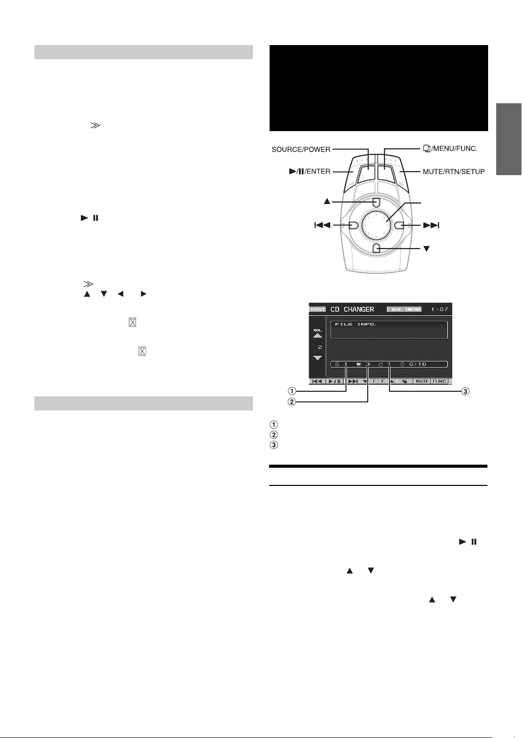
CD/MP3/WMA
Operation
(Optional)
Joystick
Display example for MP3/WMA main screen
Setting the Auxiliary Data Field Display
This display can be used only when the optional XM Satellite Radio
Receiver is connected.
Setting item: ADF
Setting content: OFF/ON
ON: The Auxiliary Data Field is displayed in the XM mode.
OFF: The Auxiliary Data Field is not displayed.
Disc number display
Folder number display
File number display
Playing CD/MP3/WMA
1
Press SOURCE/POWER.
The source selection screen is displayed.
2
Press the joystick up or down to select the CD/MP3/
WMA mode (CD CHANGER, etc.), then press //
ENTER.
3
Press and hold or for at least 2 seconds to
select a disc (when a changer is connected).
4
While playing back MP3/WMA. Press or to
select the desired folder.
17-EN
Page 20

5
Press or to select the desired track.
Returning to the beginning of the current track:
Press .
Fast reverse:
Press and hold .
Advancing to the beginning of the next track:
Press .
Fast forward:
Press and hold .
6
To pause playback, press / /ENTER.
Pressing / /ENTER again will resume playback.
• CD playback information (track no., text etc.) will be displayed on
the monitor during playback.
• MP3/WMA playback information (folder no., file no., tag
information, etc.) will be displayed on the monitor during playback.
• "NO SUPPORT" is displayed when text information is not
compatible with the VPA-B222.
• The DVD changer (optional) is controllable as well as the CD
changer.
Multi-Changer Selection
With the KCA-410C (Versatile Link Terminal), you can connect two
changers.
1
Press and hold /MENU/FUNC. for at least 2
seconds.
The FUNCTION screen is displayed.
2
Press the joystick up or down to select CHG SEL.
Then press / /ENTER to select the next changer
(connected CD changers only).
Folder/File Search
You can display the names of folders/files and search for a folder/file to
play.
1
Press /MENU/FUNC. during playback.
The Folder Name list is displayed.
2
Press the joystick up or down to select the desired
folder.
3
Press / /ENTER to play back the first file in the
selected folder.
To search for a file in the selected folder
1 After selecting the folder in step 2, press the joystick right
to change to the file search mode of the selected folder.
• If there is a file name list in the folder, is displayed.
2 Press the joystick up or down to select a file, then press
//ENTER.
The selected file is played back.
• Pressing MUTE/RTN/SETUP will return to the previous screen.
• Folder/File Name search cannot be made during M.I.X. play.
• “ROOT” is displayed for the root folder which does not have folder
name.
M.I.X. (Random Play)
1
Press and hold /MENU/FUNC. for at least 2
seconds.
The FUNCTION screen is displayed.
2
Press the joystick up or down to select M.I.X..
When M.I.X. is displayed (changer is connected)
3
Press the joystick right.
4
Press the joystick up or down to select the M.I.X.
mode, then press / /ENTER.
CD mode:
M.I.X.: Track are played back in random sequence.
M.I.X. ALL: The tracks on all the CDs in the current magazine
OFF: M.I.X. mode off.
* When a CD changer equipped with the All M.I.X. function is
connected.
MP3/WMA mode:
M.I.X. FLD: Only files in a folder are played back in random
M.I.X.: All files in a disc are played back in random
OFF: M.I.X. mode off.
When M.I.X. is displayed
3
Press / /ENTER.
M.I.X. mode is changed.
CD mode:
M.I.X. OFF M.I.X.
MP3/WMA mode:
M.I.X. FLD M.I.X. OFF M.I.X. FLD
will be included in the random playback sequence.
sequence.
sequence, and playback shifts to the next disc.
Repeat Play
1
Press and hold /MENU/FUNC. for at least 2
seconds.
The FUNCTION screen is displayed.
2
Press the joystick up or down to select REPEAT.
When REPEAT is displayed (changer is connected)
3
Press the joystick right.
4
Press the joystick up or down to select the REPEAT
mode and press / /ENTER.
CD mode:
RPT: Only a track is repeatedly played back.
RPT DISC: A disc is repeatedly played back.
OFF: Repeat mode off.
18-EN
Page 21

MP3/WMA mode:
RPT: Only a file is repeatedly played back.
RPT FLD: Only files in a folder are repeatedly played back.
RPT DISC: A disc is repeatedly played back.
OFF: Repeat mode off
When REPEAT is displayed
3
Press / /ENTER.
The repeat mode is changed.
CD mode:
RPT OFF RPT
MP3/WMA mode:
RPT RPT FLD OFF RPT
DVD/Video CD
Operation
(Optional)
Joystick
Display example for DVD main operation screen
Playing DVD/Video CD
Basic operations of an Alpine DVD player/Changer can be done from
the unit's supplied commander. Refer to the Owner's Manual of the
connected DVD player/Changer.
When using an Alpine DVD Player/Changer, some of the commander
functions may not be recognized. This varies from disc to disc. If the
supplied VPA-B222 commander is not controlling a particular function
of the DVD being played, please use the remote control that came with
the DVD player.
WARNING
It is dangerous (and illegal in many states) for the
driver to watch the DVD/TV/Video while driving the
vehicle. The driver may be distracted from looking
ahead and an accident could occur.
Install the VPA-B222 correctly so that the driver
cannot watch DVD/TV/Video unless the vehicle is
stopped and the emergency brake is applied.
If the VPA-B222 is not installed correctly, the driver
will be able to watch the DVD/TV/Video while driving
the vehicle and may be distracted from looking ahead
and cause an accident. The driver or other people
could be severely injured.
19-EN
Page 22

To display the DVD mode screen
To watch a video source, your vehicle must be parked with the ignition
key in the ACC or ON position. To do this, follow the procedure below.
1 Push the foot brake to bring your vehicle to a complete
stop at a safe location. Engage the parking brake.
2 Keep pushing the foot brake and release the parking
brake once then engage it again.
3 While the parking brake is being engaged the second
time, release the foot brake.
• For automatic transmission vehicles, place the transmission lever in
the Park position.
Now, the locking system for the DVD mode operation has been
released. Engaging the parking brake can reactivate the DVD mode, as
long as the car's ignition has not been turned off. It is not necessary to
repeat the above procedure (1 through 3), of “To display the DVD mode
screen.”
Each time the ignition is turned OFF, perform the procedure of “To
display the DVD mode screen.”
• If you try to activate the auxiliary device while driving, the display
will show the warning-PICTURE OFF FOR YOUR SAFETY.
Caution
• Not all functions will operate for every DVD. See the
individual DVD’s instructions for details on the
features supported.
• If you try to perform an invalid operation (based on
the type of disc being played), the following mark is
displayed on the monitor screen:
1
Press SOURCE/POWER.
The source selection screen is displayed.
2
Press the joystick up or down to select the DVD
mode (EXT.DVD or DVD CHANGER, etc.), then press
/ /ENTER.
Playback starts.
Playing Still Frames (Pausing)
1
During playback, press //ENTER.
2
Press / /ENTER to resume playback.
Finding the Beginnings of Chapters or
Tracks
During playback, press or .
The chapter/track switches each time the button is pressed, and
playback of the selected chapter/track starts.
: Press this to start playback from the beginning of the
following chapter or track.
: Press this to start playback from the beginning of the
current chapter or track.
• Some DVDs do not have chapters.
Supplementary explanation
“Chapters” are divisions of movies or musical selections on
DVDs.
“Tra cks ” are divisions of movies or musical selections on
video and music CDs.
Fast-forwarding/Fast-reversing
1
During playback, press and hold (fast-reverse)
or (fast-forward).
2
Release or to return to normal playback.
If a menu screen appears
On DVDs and Video CDs with playback control (PBC), menu screens
may appear automatically. The DVD menu can be controlled by the
commander supplied with the unit. If this happens, perform the
operation described below to start playback.
Press the joystick up, down, left or right to select an
item, then press and hold / /ENTER for at least
2 seconds.
• Press MUTE/RTN/SETUP to return to the previous screen.
• The Video CD menu screen cannot be controlled from the
commander supplied with the unit.
• Depending on the disc, the menu screen may be recalled from the
FUNCTION screen. Select MENU on the FUNCTION screen and
press / /ENTER to recall the menu, after displaying the
FUNCTION screen by pressing and holding /MENU/FUNC. for
at least 2 seconds.
20-EN
Page 23

Displaying the Top Menu Screen (DVD
only)
With a DVD having two or more titles, a top menu screen will appear.
Press /MENU/FUNC. on the DVD mode main screen.
The menu screen appears.
• To perform necessary operations, see “If a menu screen appears” on
page 20.
Changing Discs (only when DVD changer
is connected)
Chapter/Track/Title Repeat Playback
Use this function to play the disc’s titles, chapters or tracks repeatedly.
1
Press and hold /MENU/FUNC. for at least 2
seconds.
The FUNCTION screen is displayed.
2
Press the joystick up or down to select REPEAT,
then press / /ENTER.
The screen changes to the repeat mode in the following
step.
DVD
Press and hold or for at least 2 seconds.
The selected disc is played back.
• Select DISC SELECT on the FUNCTION screen and press //
ENTER to change discs, after pressing and holding /MENU/
FUNC. for at least 2 seconds.
Stopping Playback (PRE STOP)
Select the PRE STOP during playback to stop playback. That position is
stored in the memory.
1
During playback, press and hold /MENU/FUNC.
for at least 2 seconds.
The FUNCTION screen is displayed.
2
Press the joystick up or down to select STOP/PRE
STOP, then press / /ENTER.
"PRE STOP" is displayed.
3
During PRE STOP mode, press //ENTER.
Playback starts from the position at which it was stopped.
• For some discs, the position at which playback was stopped may not
be accurate.
• When a DVD player/changer is connected with Ai-NET, STOP/PRE
STOP is not displayed on the FUNCTION screen in the video CD
mode.
Stopping Playback
1
During the PRE STOP mode, press and hold /
MENU/FUNC. for at least 2 seconds.
The FUNCTION screen is displayed.
2
Press the joystick up or down to select STOP/PRE
STOP, then press / /ENTER.
“STOP” is displayed, and playback stops.
• Playback starts from the beginning when //ENTER is pressed
while playback is stopped.
• When a DVD player/changer is connected with Ai-NET, STOP/PRE
STOP is not displayed on the FUNCTION screen in the video CD
mode.
The chapter is played repeatedly.
The title is played repeatedly.
The playback returns to normal mode.
Video CD
The track is played repeatedly.
The disc is played repeatedly.
Playback does not repeat.
• Display may vary depending on the connected devices.
• The track/disc repeat modes cannot be used on video CDs with
playback control (PBC). These modes can be carried out after
turning PBC off.
• For some discs it is not possible to switch the repeat mode.
• The repeat mode may not be switched, depending on the connected
product.
Switching the Audio Tracks
DVDs can have up to 8 different audio tracks. These alternate tracks can
be switched during playback.
1
Press and hold /MENU/FUNC. for at least 2
seconds.
The FUNCTION screen is displayed.
2
Press the joystick up or down to select AUDIO,
then press / /ENTER.
The sound switches between the alternate audio tracks
recorded on the disc.
• The alternate track selected becomes the default setting every time
the power is turned on or the disc is replaced. If the disc does not
include that track, the disc’s default language is selected instead.
• Not all discs will allow changing the alternate audio tracks during
playback. In these cases, select audio tracks from the DVDs menu.
• There may be a delay before the selected alternate track begins to
play.
21-EN
Page 24

Video CDs with multiplex audio
1
Press and hold /MENU/FUNC. for at least 2
seconds.
The FUNCTION screen is displayed.
2
Press the joystick up or down to select AUDIO,
then press / /ENTER.
The left and right channels will be output as shown in the
figure below.
<Monitor display>
AUDIO L/R AUDIO L/L AUDIO R/R AUDIO L/R
• If a DVD player/DVD changer with Ai-NET is connected, AUDIO is
not displayed on the video CD function screen.
Switching the Subtitles (Subtitle
Language) (DVD only)
With DVDs on which multiple subtitle languages are recorded, the
subtitle language can be switched during playback; moreover, subtitles
can be hidden.
1
Press and hold /MENU/FUNC. for at least 2
seconds.
The FUNCTION screen is displayed.
2
Press the joystick up or down to select SUB
TITLE, then press //ENTER.
The subtitle language stored in the disc is changed, then
turns off.
• There may be a delay before the selected subtitle appears.
• Not all discs will allow changing the subtitles during playback. In
these cases, select subtitles from the DVDs menu.
• The subtitle language selected becomes the default setting every time
the power is turned on or the disc is replaced. If the disc does not
include that language, the disc’s default language is selected instead.
However, the subtitle language may differ depending on the disc.
• For some discs, the subtitles will be displayed even when this is set to
off. However, the subtitle language may differ depending on the disc.
Switching from the disc menu
For some discs, the audio language, angle and subtitles can be switched
from the disc menu.
1
Press and hold /MENU/FUNC. for at least 2
seconds.
The FUNCTION screen is displayed.
2
Press the joystick up or down to select MENU,
then press / /ENTER.
3
Select an item to confirm it.
See “If a menu screen appears” on page 20.
Switching the Angle (DVD only)
On DVDs in which scenes have been filmed from multiple angles, the
angle can be switched during playback.
1
Press and hold /MENU/FUNC. for at least 2
seconds.
The FUNCTION screen is displayed.
2
Press the joystick up or down to select ANGLE,
then press / /ENTER.
The angle switches between the angles recorded on the
disc.
• Some time may be required for the angle to change.
• Depending on the disc, the angle may switch in one of two ways.
- Seamless: The angle switches smoothly.
- Non-seamless: When the angle is switched, a still picture is
displayed first, after which the angle switches.
22-EN
Page 25

SAT Radio Receiver
(Optional)
Joystick
4
Press / /ENTER to select the channel tuning.
Each time it is pressed, the tuning mode is changed.
channel number tuning channel name tuning
5
Press or to select the desired channel.
Holding down or will change channels
continuously.
• When using the optional remote control (RUE-4190, etc.), an SAT
Radio Channel can be directly called up with the numeric keypad of
the remote control.
1 While in XM or SIRIUS Radio mode, enter the Channel
number you want to call up with the numeric keypad on
the remote control.
2 Press ENTER on the remote control within 5 seconds to
receive the Channel.
If the channel number is 3 digits, the Channel is
automatically received after the channel number is input.
Tuning in to Categorized Programs
SAT Receiver: XM or SIRIUS Receiver
When an optional XM or SIRIUS Receiver Box is connected
via the Ai-NET bus, the following operations may be
performed. However, the XM Receiver and SIRIUS Receiver
cannot be connected at the same time.
Receiving Channels with the SAT
Receiver
About SAT Radio
Satellite Radio* is the next generation of audio entertainment, with over
to 100 digital channels. For a small monthly fee, subscribers can hear
crystal-clear music, sports, news and talk, coast-to-coast via satellite.
For more information, visit XM’s website at www.xmradio.com., and
SIRIUS’ website at www.sirius.com.
To receive SAT Radio, the separately sold XMDirect™ or SIRIUS
Satellite Radio Tuner and an appropriate Ai-NET Interface Adapter will
be required. For details, consult you nearest Alpine dealer.
* XM and its corresponding logos are trademarks of XM Satellite
Radio Inc.
* SIRIUS and its corresponding logos are trademarks of SIRIUS
Satellite Radio Inc.
• The SAT Receiver controls on the VPA-B222 are operative only when
a SAT Receiver is connected.
1
Press SOURCE/POWER.
The source selection screen is displayed.
2
Press the joystick up or down to select the SAT
Radio mode (XM or SIRIUS).
You can listen to programs categorized to the same group one after
another.
1
In the XM or SIRIUS mode, press and hold //
ENTER for at least 2 seconds to select CATEGORY
mode.
The CATEGORY indicator lights up.
2
Press or to select the desired channel in
the category.
Holding down or will change channel
continuously.
3
To cancel the CATEGORY mode, press and hold
/ /ENTER for at least 2 seconds.
Changing the Display
Text information, such as the channel name, artist name/feature, and
song/program title, is available with each XM or SIRIUS channel. The
unit can display this text information as explained below.
1
Press and hold /MENU/FUNC. for at least 2
seconds.
The FUNCTION screen is displayed.
2
Press the joystick up or down to select INFO., then
press / /ENTER.
Each time you perform the above operations, the display
changes as shown below.
XM Radio:
3
Press and hold for at least 2 seconds to select
between one of the three SAT Radio Preset Bands.
Each press changes the band:
XM radio:
XM-1 XM-2 XM-3 XM-1
SIRIUS radio:
SIRIUS-1 SIRIUS-2 SIRIUS-3 SIRIUS-1
23-EN
Page 26

SIRIUS Radio:
*1Channel name, category, song name, etc., are displayed in one
screen.
*2XM mode only: The information display appears when ON is set in
“Setting the Auxiliary Data Field Display” (page 17).
Checking the SAT Radio ID Number
A unique Radio ID number is required to subscribe to SAT Radio
programming. Each third party XM or SIRIUS radio comes with this
number.
XM Radio:
This number is an 8 character alphanumeric number. It is printed on a
label found on the SAT Receiver.
SIRIUS Radio:
This number is a 12 character alphanumeric number. It is printed on a
label found on the SAT Receiver.
It can also be displayed on the screen of the VPA-B222 in the following
way.
1
Press / /ENTER to select the channel number
turing mode.
2
While receiving a SAT Radio band, press or
to select channel "0" for XM, or to select
channel "255" for SIRIUS.
3
The unit displays the ID number.
4
To cancel the ID number display, change the
channel.
• You cannot use “O,” “S,” “ I,” or “F” for the ID Number. (XM radio
Receiver only)
• You can check the ID number printed on a label on your third party,
SAT Radio Receiver package.
Storing Channel Presets
1
Press and hold /MENU/FUNC. for at least 2
seconds after selecting a desired band.
The FUNCTION screen is displayed.
2
Press the joystick up or down to select PRESET
MEMORY, then press the joystick right.
3
Press the joystick up or down to select any one of
the preset numbers PRESET1 through PRESET6,
then press / /ENTER.
The selected station is stored.
4
Repeat the procedure to store up to 5 other channels
onto the same band.
To use this procedure for other bands, simply select the
desired band and repeat the procedure.
A total of 18 channels can be stored in the preset memory
(6 channels for each band; XM-1, XM-2 and XM-3 or
SIRIUS-1, SIRIUS-2 and SIRIUS-3).
• If you store a channel in a preset already being used, the current
channel will be replaced with the new one.
Receiving Stored Channels
1
Press and hold for at least 2 seconds repeatedly
until the desired band is displayed.
2
Press and hold /MENU/FUNC. for at least 2
seconds.
The FUNCTION screen is displayed.
3
Press the joystick up or down to select PRESET
CALL, then press the joystick right.
4
Press the joystick up or down to select any one of
the preset numbers PRESET1 through PRESET6,
then press / /ENTER.
The selected station is received.
• During reception, you can change the station by pressing or .
24-EN
Page 27

Category/Channel Search Function
You can search for programs by Category or Channel name.
1
Press /MENU/FUNC..
The Category Search screen is displayed.
2
Press the joystick up or down to select your
desired category.
To receive the category directly
1
Press / /ENTER.
The first channel of the selected category is tuned.
To search for a channel in the category
1
Press the joystick right to change to the channel
search mode of the selected category .
2
Press the joystick up or down to select a channel,
then press / /ENTER.
The selected channel is received.
Storing Weather or Traffic information
from SAT Radio
1
While receiving weather or Traffic information in the
SAT Radio mode, press and hold /MENU/FUNC.
for at least 2 seconds.
The FUNCTION screen is displayed.
2
Press the joystick up or down to select WEATHER
MEMORY, then press / /ENTER.
The received weather or traffic channel is stored.
iPod® (Optional)
Joystick
An iPod® can be connected to the VPA-B222 by using the proprietary
ALPINE FULL SPEED™ Connection Cable (KCE-422i). When the
VPA-B222 is connected by using the cable, the controls on the iPod are
not functional.
About iPod usable with this unit
The unit can be used with third generation and above iPod, iPod photo,
iPod minis or iPod nano. iPod Shuffle cannot be used, however.
• Touch wheel or scroll wheel type iPods without the dock
connector cannot be connected to the unit.
• The unit can be used with the following iPod versions.
Correct function of earlier versions cannot be guaranteed.
Third generation iPod: Ver. 2.3
Fourth generation iPod: Ver. 3.0.2
iPod photo: Ver. 1.1
iPod mini: Ver. 1.3
iPod nano: Ver. 1.0
• The unit cannot be used with the software versions earlier
than 2005-02-22. For details about "iPod Software Update,"
refer to the iPod Instruction Manual.
Receiving Weather or Traffic Information
from SAT Radio
1
In the SAT Radio mode, press and hold /MENU/
FUNC. for at least 2 seconds.
The FUNCTION screen is displayed.
2
Press the joystick up or down to select WEATHER
CALL, then press / /ENTER.
The weather or traffic channel is recalled.
3
Press MUTE/RTN/SETUP to return to normal
mode.
• When activated in a mode other than SAT Radio, the stored weather
or traffic channel can be received.
Playback
1
Press SOURCE/POWER.
The source selection screen is displayed.
2
Press the joystick up or down to select iPod, then
press / /ENTER.
3
Press or to select the desired song.
Return to the beginning of the current song:
Press .
Fast reverse:
Press and hold .
Advance to the beginning of the next song:
Press .
Fast forward:
Press and hold .
4
To pause playback, press //ENTER. Pressing
/ /ENTER again will resume playback.
25-EN
Page 28

• If a song is playing on the iPod when it is connected to the
VPA-B222, it will continue playing after the connection.
• If the artist, album or song name, created in iTunes, has too many
characters, songs may not be played back when connected to the
adapter. Therefore, a maximum of 250 characters is recommended.
The maximum number of characters for the head unit is 64 (64 byte).
• Some characters may not be correctly displayed.
• “NO SUPPORT” is displayed when text information is not
compatible with the VPA-B222.
Searching for a desired Song
Searching by artist name
1
Press /MENU/FUNC..
The search mode is activated, and the search list screen
appears.
2
Press the joystick up or down to select ARTIST
SEARCH, then press the joystick right.
3
Press the joystick up or down to select the artist to
be played back.
An iPod can contain hundreds to thousands of songs. By keeping these
songs organized in smaller playlists, the VPA-B222 has the ability to
ease song searches.
• During shuffle (M.I.X.) playback, this operation is not possible.
Searching by Playlist
1
Press /MENU/FUNC..
The search mode is activated, and the search list screen
appears.
2
Press the joystick up or down to select PLAYLIST
SEARCH, then press the joystick right.
3
Press the joystick up or down to select the playlist.
To play back the playlist directly
1Press //ENTER.
The selected playlist is played back repeatedly.
To search for a song in the playlist
1 Press the joystick right to change to the song search
mode of the selected playlist.
2 Press the joystick up or down to select a song, then press
//ENTER.
The selected song is played back.
To play back the artist directly
1 Press / /ENTER.
Songs by the selected artist are played back.
• Selecting ALL and pressing //ENTER plays back all songs
from the beginning.
• Selecting ALL and pressing the joystick right will change to the
ALBUM search screen.
To search for the album of an artist
1 Press the joystick right to change to the album search
mode of the selected artist.
2*1Press the joystick up or down to select the album to be
played back.
3 Press / /ENTER to play back all songs of the
selected album.
Songs in the selected album are played back.
• Selecting ALL and pressing //ENTER will play back the first
song of the selected artist.
• Selecting ALL and pressing the joystick right will change to the
SONG search screen of the selected artist
To search for a song in the album of an artist
1 After selecting the album in step 2*1, press the joystick
right to change to the song search mode of the selected
album.
2 Press the joystick up or down to select a song, then press
//ENTER.
The selected song is played back.
26-EN
Searching by album name
1
Press /MENU/FUNC..
The search mode is activated, and the search list screen
appears.
2
Press the joystick up or down to select ALBUM
SEARCH, then press the joystick right.
3
Press the joystick up or down to select the album
to be played back.
Page 29

To play back the album directly
1Press //ENTER.
Songs in the selected album are played back.
• Selecting ALL and pressing / /ENTER plays back all songs
from the beginning.
• Selecting ALL and pressing the joystick right will change to the
SONG search screen.
To search for a song in an album
1 Press the joystick right to change to the song search
mode of the selected album.
2 Press the joystick up or down to select a song, then press
//ENTER.
The selected song is played back.
Searching by Song Name
1
Press /MENU/FUNC..
The search mode is activated, and the search list screen
appears.
2
Press the joystick up or down to select SONG
SEARCH, then press the joystick right.
3
Press the joystick up or down to select a song, then
press / /ENTER.
The selected song is played back.
3
Press the joystick up or down to select the M.I.X.
mode, then press / /ENTER.
M.I.X. ALBUM:
Album shuffle playback plays back all songs in order, then randomly
selects the next album. All songs of that album are played back in order,
and so on. Any one album is played just once.
M.I.X. SONGS:
Song shuffle randomly plays back certain selected songs. Any one song
plays back just once until all songs have been played back.
M.I.X. ALL:
Shuffle ALL plays all songs in the iPod randomly. Any one song does
not play back again until all songs have been played back.
OFF:
M.I.X. mode is off.
4
To cancel M.I.X. play, select OFF in step 3, and press
/ /ENTER.
• For details of the search mode, refer to "Searching for a desired
Song" (page 26).
• If a song is selected in the album search mode before selecting
Shuffle (M.I.X.), the songs will not play back randomly even when
Shuffle album is selected.
• If Shuffle ALL is selected, the selected ones which played back in the
search mode are canceled.
Select Playlist/Artist/Album
Playlist/Artist/Album can be easily changed.
For example, if you listen to a song from a selected album, the album
can be changed.
1
Press or to select the desired Playlist/Artist/
Album.
• If search selection mode is not activated, only SONG is searched, this
operation is not possible.
• If an album is selected from an artist search, the album can be
searched.
• During shuffle (M.I.X.) playback, this operation is not possible.
Random Play Shuffle (M.I.X.)
The Shuffle function of the iPod is displayed as M.I.X. on the VPAB222.
1
Press and hold /MENU/FUNC. for at least 2
seconds.
The FUNCTION screen is displayed.
2
Press the joystick up or down to select M.I.X., then
press the joystick right.
Repeat Play
Only Repeat One is available for the iPod.
Repeat One: A single song is repeatedly played back.
1
Press and hold /MENU/FUNC. for at least 2
seconds.
The FUNCTION screen is displayed.
2
Press the joystick up or down to select REPEAT,
then press the joystick right.
3
Press the joystick up or down to select RPT, then
press / /ENTER.
The track is played back repeatedly.
4
To cancel repeat play, select OFF in step 3, and
press / /ENTER.
• During repeat playback, no other songs are selectable by pressing
or .
• The repeat mode is canceled when iPod or iPod mini is removed or
the ignition key is turned off.
27-EN
Page 30

Navigation System
Map Screen Function
(Optional)
Joystick
Basic Alpine navigation control can be performed by the commander
supplied with the unit. Refer to the Owner's Manual of the navigation.
• If a navigation system that is not controlled by the remote control, but
touch-panel operation only is connected, operations cannot be
performed by the commander.
Displaying the Navigation Screen
When an Alpine navigation system is connected, the navigation screen
can easily be displayed.
Displaying the Current Position
1
Press NAV./POS. while displaying the map screen.
The current position screen is displayed.
Scrolling the Map
1
Press the joystick.
The map scrolls in the direction the joystick is pressed.
Changing the Map Scale
1
Press or .
Each press of the button changes the map scale. Pressing
and holding changes the scale continuously.
Menu Screen Function
1
Press /MENU/FUNC. in the Navigation mode.
The Navigation Menu screen is displayed.
2
Press the joystick up, down, left or right to select
the desired item.
3
Press / /ENTER.
• Press MUTE/RTN/SETUP to return to the previous screen.
1
Press DISP..
The Navigation screen is displayed.
2
To cancel the screen, press DISP. again.
Changing the Navigation operation mode
When an Alpine navigation system is connected, the navigation screen
can easily be displayed, and some operations can be performed.
1
Press NAV./POS..
The navigation screen is displayed, and the navigation
mode becomes active.
2
Press DISP. to cancel the operation mode, and
return to the main source screen before the
operation was performed.
When DISP. is pressed and held for at least 2 seconds, the
operation mode is canceled, the navigation screen display
remains, and the sound returns to the selected source
before the operation was performed.
• If the navigation mode is selected on the source selection screen, the
navigation mode is not canceled even if DISP. is pressed.
• The color of the commander buttons illumination changes in the
navigation mode. Refer to "Setting the Color of the Commander
Button Illumination" (page 16).
28-EN
Page 31

TV Operation
(Optional)
Joystick
When connected to an Alpine TV unit (sold separately), you can use the
commander supplied with the VPA-B222 to operate the TV. Set the
AUX NAME to TV. Refer to "Naming External Devices" page 15.
• When the optional expansion box (VPE-S431) is connected, connect
TV to AUX IN-2, 3.
• Be sure to connect this unit or VPE-S431 remote control output lead
to the TV unit's remote control input lead.
• For details, refer to the owner's manual of the TV unit.
Operating TV Unit
WARNING
It is dangerous (and illegal in many states) for the
driver to watch the TV while driving the vehicle. The
driver may be distracted from looking ahead and an
accident could occur.
To activate your TV unit:
To watch a video source, your vehicle must be parked with the
ignition key in the ACC or ON position. To do this, follow the
procedure below.
1 Bring your vehicle to a complete stop at a safe
location. Engage the parking brake.
2 Keep pushing the foot brake and release the parking
brake once then engage it again.
3 When the parking brake is engaged for the second
time, release the foot brake.
• For automatic transmission vehicles, place the transmission lever
in the Park position.
Now, the locking system for the TV mode operation has been
released. Engaging the parking brake can reactivate the TV
mode, as long as the car's ignition has not been turned off. It is
not necessary to repeat the above procedure (1 through 3), of "To
activate your TV unit."
Each time the ignition is turned OFF, perform the procedure of "To
activate your TV unit."
• If you try to activate the TV unit while driving, the display will
show the warning-PICTURE OFF FOR YOUR SAFETY.
1
Press SOURCE/POWER.
The source selection screen is displayed.
2
Press the joystick up or down to select TV, then
press / /ENTER.
3
Press and hold for at least 2 seconds to select
BAND.
4
Press / /ENTER to switch the manual tuning
mode.
Manual tune (Auto seek tune) Preset number tune
5
Press or to change the channel up or
down one by one. (manual mode)
The channel is searched and received automatically by
pressing and holding. (Auto seek mode)
Install the VPA-B222 correctly so that the driver
cannot watch TV unless the vehicle is stopped and
the emergency brake is applied.
If the VPA-B222 is not installed correctly, the driver
will be able to watch the TV while driving the vehicle
and may be distracted from looking ahead and cause
an accident. The driver or other people could be
severely injured.
Automatic Memory of Channel Presets
1
Press and hold / /ENTER for at least 2 seconds.
The auto preset operation starts.
After the completion, memorized channel number list
displays and the first memorized station is automatically
received.
2
To receive a memorized station, press / /ENTER
to switch the preset number tuning mode.
Manual tune (Auto seek tune) Preset number tune
3
Press or to select a preset number.
Switching Audio
1
Press and hold /MENU/FUNC. for at least 2
seconds.
The FUNCTION screen is displayed.
2
Press the joystick up or down to select AUDIO,
then press / /ENTER.
The audio mode is changed.
29-EN
Page 32

Auxiliary Device
(Optional)
Operating Auxiliary Devices (Optional)
To operate devices connected to the AUX terminals of VPA-B222,
follow the procedure described below.
WARNING
It is dangerous (and illegal in many states) for the
driver to watch the TV/Video while driving the vehicle.
The driver may be distracted from looking ahead and
an accident could occur.
Install the VPA-B222 correctly so that the driver
cannot watch TV/Video unless the vehicle is stopped
and the emergency brake is applied.
If the VPA-B222 is not installed correctly, the driver
will be able to watch the TV/Video while driving the
vehicle and may be distracted from looking ahead and
cause an accident. The driver or other people could
be severely injured.
1
Press SOURCE/POWER.
The source selection screen is displayed.
2
Press the joystick up or down to select the AUX
mode, then press / /ENTER.
The external input screen is displayed.
• AUX-1 to AUX are displayed if AUX IN set to ON in “Setting the
AUX mode” (page 15), or the name which is given as the source
name in “Naming External Devices” on page 15 is displayed.
• AUX-3 is displayed when the optional expansion box (VPE-S431) is
connected.
• When the Versatile Link Terminal (KCA-410C) is connected, external
input to KCA-410C is unavailable. However, when IN-INT MUTE is
set to off, the sound of a device connected to the external input of
KCA-410C can be interrupted. (See "Setting the External Device
Interrupt Mode" page 16.)
To activate your auxiliary devices:
To watch a video source, your vehicle must be parked with the
ignition key in the ACC or ON position. To do this, follow the
procedure below.
1 Bring your vehicle to a complete stop at a safe
location. Engage the parking brake.
2 Keep pushing the foot brake and release the parking
brake once then engage it again.
3 When the parking brake is engaged for the second
time, release the foot brake.
• For automatic transmission vehicles, place the transmission lever
in the Park position.
Now, the locking system for the AUX mode operation has been
released. Engaging the parking brake can reactivate the AUX
mode, as long as the car's ignition has not been turned off. It is
not necessary to repeat the above procedure (1 through 3), of
“To activate your auxiliary devices.”
Each time the ignition is turned OFF, perform the procedure of “To
activate your auxiliary devices.”
• If you try to activate an auxiliary device while driving, the
display will show the warning-PICTURE OFF FOR YOUR
SAFETY.
30-EN
Page 33

Factory System HDD Player
Operation
Operating Factory System (Speaker
Input mode)
The car’s system (standard CD player, etc.) can be selected as a source.
1
Press SOURCE/POWER.
The source selection screen is displayed.
2
Press the joystick up or down to select the
FAC TORY S YS mode, then press / /ENTER.
The speaker input screen is displayed.
• FACTORY SYS mode is displayed when SOURCE or BOTH is set in
"Setting the Speaker Input Mode" (page 14).
• Make each setting correctly in “Using the Speaker Input” (page 14)
before use this function.
(Optional)
Listening to Music of HDD
This device is controllable from the when Alpine HDD player is
connected.
1
Press SOURCE/POWER.
The source selection screen is displayed.
2
Press the joystick up or down to select the MM
DRIVER, then press / /ENTER.
The MM DRIVER mode main screen is displayed.
3
Press or to select the desired track.
Returning to the beginning of the current track:
Press .
Fast reverse:
Press and hold .
Advancing to the beginning of the next track:
Press .
Fast forward :
Press and hold .
4
To pause playback, press //ENTER.
Pressing / /ENTER again will resume playback.
31-EN
Page 34

External Audio
Adjustment Procedure for Dolby
Surround
Processor
(Optional)
Joystick
When an external audio processor is connected to this unit, you can
operate it from this unit. Some audio processors may not be operated.
Explanations below is the case when PXA-H700 or PXA-H701 is
connected for example.
Refer also to the operating instructions of the connected audio
processor.
• The adjustments or settings performed on the connected audio
processor cannot be operated properly from this unit.
• The setting "Setting the Speakers", "Setting Bass Sound Control",
and "Graphic Equalizer Adjustments" are not available if the MRDD550 is connected. Additionally, if the MRD-F350 is connected, the
following setting "Setting the MX mode" is not available. Also, the
setting content differs between the PXA-H700 and PXA-H701.
To display the Audio processor mode screen:
To watch a video source, your vehicle must be parked with the
ignition key in the ACC or ON position. To do this, follow the
procedure below.
1 Bring your vehicle to a complete stop at a safe
location. Engage the parking brake.
2 Keep pushing the foot brake and release the parking
brake once then engage it again.
3 When the parking brake is engaged for the second
time, release the foot brake.
• For automatic transmission vehicles, place the transmission lever
in the Park position.
Now, the locking system for the Audio processor mode operation
has been released. Engaging the parking brake can reactivate
the Audio processor mode, as long as the car's ignition has not
been turned off. It is not necessary to repeat the above
procedure (1 through 3), of “To display the Audio processor
mode screen.”
Each time the ignition is turned OFF, perform the procedure of “To
display the Audio processor mode screen.”
Make the adjustments described below in order to reproduce Dolby
Digital and DTS sound with greater accuracy.
Adjustment procedure
Speaker Setup (page 36)
1
(Turning the speakers to be used on and off and
setting their response)
Adjusting the speaker levels (page 37)
2
(Adjusting the signal output level to the various
speakers)
Mixing bass sound to the rear channel
3
(page 37)
(Achieving smooth sound in the rear seat by mixing
the front audio signals with the rear speaker signals)
Adjusting the acoustic image (page 37)
4
(Adjusting the acoustic image to achieve a sound as
if the center speaker were directly in front of the
listener)
Achieving powerful high volume sound
5
(page 37)
(Achieving energetic sound with even greater power,
like the sound in a movie theater)
Adjusting the DVD Level (page 38)
6
(Adjust the volume (signal level) in the Dolby Digital,
Pro Logic II, DTS and PCM modes)
Storing Settings in the Memory (page 38)
7
(Storing all the settings and adjustments made on the
VPA-B222 (not only the above settings/adjustments)
in the memory)
32-EN
In case of combining the Automatic adjustments, etc.
We recommend to make the Automatic adjustments before the Dolby
Surround adjustments.
Page 35

Setting the Speakers
1
Check that Defeat mode is off (page 10).
2
Press and hold MUTE/RTN/SETUP for at least 2
seconds.
The SETUP screen is displayed.
3
Press the joystick up or down to select AP SETUP,
then press the joystick right.
The AP SETUP screen is displayed.
4
Press the joystick up or down to select SPEAKER
SEL, then press the joystick right.
5
Press the joystick left or right to set the connected
speaker.
FRONT1: OFF/FULL (Full Range)/TW (Tweeter)
FRONT2: OFF/ON
REAR: OFF/ON
CENTER: OFF/ON
SUBWOOFER: OFF/MONO/STEREO
6
Repeat step 4 and 5 to set all other speakers.
7
Press MUTE/RTN/SETUP to return to the previous
screen.
• Set any unconnected speakers to OFF.
• Settings above can be carried out even when the speaker is set to
OFF in “Speaker Setup” (page 36).
• To use the subwoofer in MONO with PXA-H700 or PXA-H701
connected, connect the subwoofer to the subwoofer output terminal
of PXA-H700 or PXA-H701.
6
Press the joystick up or down to select the media
that is being played back. Then press the joystick
left or right to set the desired MX mode.
MX CD (OFF, CD 1 to 3)
CD mode processes a large quantity of data. This data is used
to reproduce the sound cleanly by making use of the data
quantity.
MX COMPM (OFF, CMPM 1 to 3) / MX SAT (OFF, SAT 1 to 3)
This corrects information that was omitted at the time of
compression. This reproduces a well-balanced sound close to
the original.
MX FM (OFF, FM 1 to 3)
The medium to high frequencies become more clear, and
produces well balanced sound in all the bands.
MX DVD (OFF, MOVIE 1 to 2)
The dialog portion of the video is reproduced more clearly.
(MUSIC)
This disk contains a large quantity of data, such as a music clip.
MX uses this data to reproduce the sound accurately.
MX AUX 1 to 3 (OFF, CMPM, MOVIE, MUSIC)
Choose the MX mode (CMPM, MUSIC, or MOVIE) that
corresponds to the media connected.
7
Press MUTE/RTN/SETUP to return to the previous
screen.
• The contents of MX set here is reflected in PXA-H700 or PXA-H701.
• When OFF is selected, MX effect of each MX mode will be OFF.
• Each music source, such as radio, CD, and MP3 can have its own
MX setting.
• MX mode does not function when MX is ON for AM radio.
• MX COMPM is applied for MP3/WMA, MMD, iPod.
• MX SAT is applied for XM, SIRIUS, HD Radio.
• MX mode can only be set for media currently playing back.
• AUX3 can be set only when the optional expansion box VPE-S431 is
connected.
Set MX Mode of the External Audio
Processor
Before performing the operations below, set MX (Media Xpander)
mode of the PXA-H700 to “AUTO” when the PXA-H700 is connected.
1
Check that Defeat mode is off (page 10).
2
Press and hold MUTE/RTN/SETUP for at least 2
seconds.
The SETUP screen is displayed.
3
Press the joystick up or down to select AP SETUP,
then press the joystick right.
The AP SETUP screen is displayed.
4
Press the joystick up or down to select MX, then
press joystick left or right to select ON.
5
Press the joystick up or down to select MX
SETUP, then press the joystick right.
X-OVER Adjustment
1
Check that Defeat mode is off (page 10).
2
Press and hold MUTE/RTN/SETUP for at least 2
seconds.
The SETUP screen is displayed.
3
Press the joystick up or down to select AP SETUP,
then press the joystick right.
The AP SETUP screen is displayed.
4
Press the joystick up or down to select
X-OVER.
5
Press the joystick left or right to select L/R or L+R.
6
Press the joystick up or down to select X-OVER
SETUP, then press the joystick right.
7
Press the joystick up or down to select the desired
speaker, then press the joystick right.
33-EN
Page 36

8
Press the joystick up or down to select the desired
item, then press the joystick left or right to adjust
the crossover.
FREQUENCY: Adjust the H.P.F. or L.P.F. cutoff frequency.
LEVEL: Adjust the H.P.F. or L.P.F. level.
SLOPE: Adjust the H.P.F. or L.P.F. slope.
To adjust other channels, repeat steps 7 and 8.
9
Press MUTE/RTN/SETUP to return to the previous
screen.
• When the speaker is set to the “OFF” mode, the X-OVER for that
speaker cannot be set. Refer to “Setting the Speakers” (page 33).
• Check the playback frequencies of the connected speakers before
adjusting.
• In order to protect the speakers, there is no OFF setting for the
subwoofer low pass filter (the slope remains the same).
• The H.P.F. filter cannot be set to OFF (slope OFF) if Tweeter is
selected for FRONT1.
The adjustable bands differ according to the
channel (speaker).
Adjustable level: -13 to 0
Adjustable slope: OFF/-6/-12/-18/-24/-30
Performing Time Correction Manually
(TCR)
Because of the particular conditions inside the vehicle, there can be
major differences in the distances between the various speakers and the
listening position. It is possible to calculate the optimum correction
values and eliminate the time error at the listening position yourself
using this function.
1
Check that Defeat mode is off (page 10).
2
Sit in the listening position (the driver’s seat, for
example) and measure the distance (in meters)
between your head and the various speakers.
3
Calculate the difference in distance between the
farthest speaker and the other speakers.
L = (distance of farthest speaker)
– (distance of other speakers)
4
Divide the distances calculated for the different
speakers by the speed of sound (343 m/s
temperature 20 °C).
This value is the time correction value for the various
speakers.
Concrete examples
Calculating the time correction value for the front left speaker on
the diagram below.
Conditions:
Distance between farthest speaker and listening position:
2.25 m (88-3/4")
Distance between front left speaker and listening position:
0.5 m (20")
Calculation:
L = 2.25 m (88-3/4") – 0.5 m (20")= 1.75 m (68-3/4")
Compensation time = 1.75 ÷ 343 x 1000 = 5.1 (ms)
In other words, setting the time correction value for the front left
speaker to 5.1 (ms) sets a virtual distance matching the
distance to the farthest speaker.
5.1ms
0.5m
2.25m
The sound is uneven because
the distance between the
listening position and the
different speakers is different.
The difference in the distance
between the front left and rear
right speakers is 1.75 meters
(68-3/4").
5
Press and hold MUTE/RTN/SETUP for at least 2
seconds.
The SETUP screen is displayed.
6
Press the joystick up or down to select AP SETUP,
then press the joystick right.
The AP SETUP screen is displayed.
7
Press the joystick up or down to select TCR.
8
Press the joystick left or right to select L/R or L+R.
L/R: Different adjustment values can be set for the left and
right channels.
L+R: Sets the same adjustment values for the left and right
channels.
9
Press the joystick up or down to select
TCR SETUP, then press the joystick right.
10
Press the joystick up or down to select the desired
speaker.
11
Press the joystick left or right to adjust the
calculated time correction value (0.00 to 20.00ms).
(1step=0.05ms)
Time correction value changes continuously by pressing
and holding the joystick.
12
Press MUTE/RTN/SETUP to return to the previous
screen.
• When the speaker is set to the “OFF” mode, the TCR for that
speaker cannot be set. Refer to “Setting the Speakers” (page 33).
• The adjustment value for FRONT2 (Speakers) which is adjusted in
time correction, is also applied to the front speakers in “Setting Bass
Focus” (page 36).
• The adjustment (AUTO TCR) cannot be automatically set on this
unit.
Time correction eliminates
the difference between the
time required for the sound
from the different speakers to
reach the listening position.
Setting the time correction of
the front left speaker to 5.1
ms makes it possible to
coordinate the distance from
the listening position to the
speaker.
34-EN
Page 37

Phase Switching
1
Check that the Defeat mode is off (page 10).
2
Press and hold MUTE/RTN/SETUP for at least 2
seconds.
The SETUP screen is displayed.
3
Press the joystick up or down to select AP SETUP,
then press the joystick right.
The AP SETUP screen is displayed.
4
Press the joystick up or down to select PHASE
SETUP, then press the joystick right.
5
Press the joystick up or down to select the desired
speaker.
6
Press the joystick left or right to switch the phase
(0°or 180°).
7
Press MUTE/RTN/SETUP to return to the previous
screen.
Graphic Equalizer Adjustments
The graphic equalizer allows you to modify the sound using 31 bands
each for the front (left and right), rear (left and right) and center
speakers. An additional 10 bands are available for the subwoofer. This
allows you to customize the sound to suit your taste.
1
Check that the Defeat mode is off (page 10).
2
Press and hold MUTE/RTN/SETUP for at least 2
seconds.
The SETUP screen is displayed.
3
Press the joystick up or down to select AP SETUP,
then press the joystick right.
The AP SETUP screen is displayed.
4
Press the joystick up or down to select G-EQ.
5
Press the joystick left or right to select L/R or L+R.
L/R: Different adjustment values can be set for the left and
right channels.
L+R: Sets the same adjustment values for the left and right
channels.
When parametric EQ is adjusted, this setting will be turned
off.
6
Press the joystick up or down to select G-EQ
SETUP, then press the joystick right.
7
Press the joystick up or down to select the desired
channel, then press the joystick right.
8
Press the joystick up or down to select the desired
frequency.
9
Press the joystick left or right to adjust the level of
the desired frequency.
Adjustable level: -9 to +9
To adjust other frequencies, repeat steps 8 and 9.
To adjust other channels, repeat steps 7 and 9.
10
Press MUTE/RTN/SETUP to return to the previous
screen.
• When the speaker is set to the “OFF” mode, the graphic equalizer
for that speaker cannot be set. Refer to “Setting the Speakers”
(page 33).
• Check the playable frequency ranges of the connected speakers
before making the equalizer adjustments. If the speaker’s playable
frequency range is 55 Hz to 30 kHz, for example, adjusting the 40 Hz
or 20 Hz band has no effect. Additionally, you may overload and
damage the speakers.
• When graphic EQ is adjusted, the adjustment for parametric EQ
becomes ineffective.
Parametric Equalizer Adjustments
The frequency bands of the graphic equalizer are fixed. This makes it
very difficult to correct for undesired peaks and dips at specific
frequencies. The parametric equalizer’s center frequency can be tuned
to these specific frequencies. Then, the bandwidth (Q) and level are
fine-tuned, independently, to make the necessary corrections. The
parametric equalizer function is an advanced tool for serious
audiophiles.
1
Check that Defeat mode is off (page 10).
2
Press and hold MUTE/RTN/SETUP for at least 2
seconds.
The SETUP screen is displayed.
3
Press the joystick up or down to select AP SETUP,
then press the joystick right.
The AP SETUP screen is displayed.
4
Press the joystick up or down to select P-EQ.
5
Press the joystick left or right to select L/R or L+R.
L/R: Different adjustment values can be set for the left and
right channels.
L+R: Sets the same adjustment values for the left and right
channels.
When graphic EQ is adjusted, this setting will be turned off.
6
Press the joystick up or down to select P-EQ
SETUP, then press the joystick right.
7
Press the joystick up or down to select the desired
channel, then press the joystick right.
8
Press the joystick up or down to select the desired
band, then press the joystick right.
9
Press the joystick up or down to select the desired
item, then press the joystick left or right to adjust
the desired mode.
To adjust other bands, repeat steps 8 and 9.
To adjust other channels, repeat steps 7 and 9.
FREQUENCY: Selects the frequency.
LEVEL: Adjusts the level.
Q: Adjust the bandwidth.
Adjustable level: -9 to +9
Adjustable bandwidth: 0.5/1/2/3/4/5
35-EN
Page 38

10
Press MUTE/RTN/SETUP to return to the previous
screen.
• When the speaker is set to the “OFF” mode, the parametric
equalizer for that speaker cannot be set. Refer to “Setting the
Speakers” (page 33).
• It is not possible to adjust the frequencies of adjacent bands within 7
steps.
• Check the playable frequency ranges of the connected speakers
before making the equalizer adjustments. If the speaker’s playable
frequency range is 55 Hz to 30 kHz, for example, adjusting the 40 Hz
or 20 Hz band has no effect. Additionally, you may overload and
damage the speakers.
• When the parametric EQ is adjusted, the adjustment for graphic EQ
becomes ineffective.
Setting Bass Sound Control
1
Check that Defeat mode is off (page 10).
2
Press and hold MUTE/RTN/SETUP for at least 2
seconds.
The SETUP screen is displayed.
3
Press the joystick up or down to select AP SETUP
and press the joystick right.
The AP SETUP screen is displayed.
4
Press the joystick up or down to select B.SOUND
CNTL, then press the joystick right.
Setting Bass Compressor
You can adjust the sound of low frequencies as desired.
5
Press the joystick up or down to select BASS
COMP.
6
Press the joystick left or right to select the desired
mode.
Bass sound is emphasized more as the mode is
sequentially switched as MODE1 2 3, offering you
vivid low frequencies.
Select OFF when the setting is not necessary.
Press MUTE/RTN/SETUP to return to the previous screen.
Setting Bass Focus
Using the previously specified delay number (time difference) allows
you to set a time difference between the front-rear/left-right speakers.
Namely, it enables a time correction based on your preference. With an
initial delay of 0.05 ms for each of the 0 to 400 steps, audible time
correction can be achieved.
Speaker Setup
The PXA-H700 or PXA-H701 can be set according to the playable
frequency range of your speakers.
Check the playable frequency range of the speakers (not including the
subwoofer) before performing this operation to verify whether the
speakers can play low frequencies (of about 80 Hz or less).
• Avoid stopping, pausing, switching the disc, cueing, fast-forwarding
or switching the audio channel of this unit while making this
adjustment. The setting is canceled if Decode mode is switched.
1
Check that Defeat mode is off (page 10).
2
Press and hold MUTE/RTN/SETUP for at least 2
seconds.
The SETUP screen is displayed.
3
Press the joystick up or down to select AP SETUP,
then press the joystick right.
The AP SETUP screen is displayed.
4
Press the joystick up or down to select SPEAKER
SETUP, then press the joystick right.
5
Press the joystick up or down to select the desired
speaker.
6
Press the joystick left or right to select the speaker
characteristic.
OFF*1: When no speaker is connected.
SMALL: When a speaker that cannot play low frequencies
LARGE*
*1It is not possible to set the front speakers to “OFF”.
*2If the front speakers are set to “SMALL”, the rear and
7
Repeat step 5 and 6 to set each speaker.
• If the center speaker is turned “OFF,” the center channel’s audio
signals are added to the audio signals output from the front speakers.
• If you set the speaker response to “OFF,” also set the speaker setting
to “OFF” (page 33).
• Perform the setup for all the speakers (“Front,” “Center,” “Rear”
and “Subwoofer”). Otherwise, the sound may not be balanced.
• When the center speaker is set to “OFF”, the setting is ineffective
even if center is set with this function.
• Through changing the settings on each speaker, a change in the
output of the other speakers may occur due to the setting
requirements.
• When using PRO LOGIC II, if the rear speaker is set to “LARGE”,
there will be no output from the subwoofer.
(80 Hz or less) is connected.
2
: When a speaker that can play low frequencies (80
Hz or less) is connected.
center speakers cannot be set to “LARGE”.
5
Press the joystick up or down to select the desired
speaker.
6
Press the joystick left or right to adjust the front,
rear, left and right speakers.
7
Repeat step 5 and 6 to set other speakers.
• Any setting in Bass Focus is applied in time correction, too.
• Press MUTE/RTN/SETUP to return to the previous screen.
36-EN
Page 39

Setting of Dolby Digital
1
Check that Defeat mode is off (page 10).
2
Press and hold MUTE/RTN/SETUP for at least 2
seconds.
The SETUP screen is displayed.
3
Press the joystick up or down to select AP SETUP,
then press the joystick right.
The AP SETUP screen is displayed.
4
Press the joystick up or down to select MULTI CH
SET, then press the joystick right.
The MULTI CH SET screen is displayed.
5
Press the joystick up or down to select the desired
item.
Set the items below as you desire.
Adjusting the acoustic image
In most installations, the center speaker must be placed directly between
the front passenger and driver. Using this function, the center channel
information is distributed to the left and right speakers. This creates an
acoustic image simulating a center speaker directly in front of each
listener. Adjusting the center width in PL II MUSIC (see “Using the Pro
Logic II Mode,” page 38), makes this function ineffective.
• Avoid stopping, pausing, switching the disc, cueing, fast-forwarding
or switching the audio channel of this unit while making this
adjustment. The setting is canceled if the Decode mode is switched.
1 Press the joystick left or right to select ON of BI-
PHANTOM.
2 Press the joystick down to select BI-PHANTOM LV.
3 Press the joystick left or right to adjust the level.
The level can be adjusted within the range of -5 to +5. The
higher the level, the more the position of the center speaker is
shifted to the sides.
The BI-PHANTOM function is turned off when setting to
OFF.
• This adjustment is effective when the setting of the center speaker to
SMALL or LARGE in the speaker setup settings.
• This adjustment is ineffective when the speaker is set to CENTER
OFF in “Setting the Speakers” (page 33).
Mixing bass sound to the rear channel
This function mixes the front channel audio signals to the audio signals
output from the rear speakers, improving the sound in the vehicle’s rear
seat.
• Avoid stopping, pausing, switching the disc, cueing, fast-forwarding
or switching the audio channel of this unit while making this
adjustment. The setting is canceled if the Decode mode is switched.
1 Press the joystick left or right to select ON of REAR MIX.
2 Press the joystick down to select MIX LEVEL.
3 Press the joystick left or right to adjust the level.
The level can adjusted in five steps: -6, -3, 0, +3 and +6. The
higher the level, the more bass is output from the rear speakers.
(The effect differs depending on to the software (DVD, etc.)).
The REAR MIX function is turned off when set to OFF.
• This adjustment is ineffective when the rear speaker setup setting is
set to “OFF”.
• For linear PCM signals, the voice is output from the rear speaker
regardless of the REAR FILL and REAR MIX setting.
Achieving powerful high volume sound
With Dolby Digital, the dynamic range is compressed so that powerful
sound can be achieved at regular volume levels. This compression can
be canceled to achieve an energetic sound with even greater power, like
the sound in a movie theater.
This function works only in the Dolby Digital mode.
Press the joystick left or right to select STD or MAX. of
LISTENING.
STD: For powerful sound at regular volume levels
MAX.: For powerful sound at high volumes
• Keep the volume to a level at which sounds outside the vehicle can
still be heard.
Adjusting the speaker levels
The test tones help to make the volume adjustments of the different
speakers. When levels are equal, a strong sense of presence can be heard
from the different speakers at the listening position.
• Avoid stopping, pausing, switching the disc, cueing, fast-forwarding
or switching the audio channel of this unit while making this
adjustment. The setting is canceled if the decode mode is switched.
1 Press the joystick left or right to select ON of OUTPUT.
Test tone output is repeated for each of the different
speaker channels. They will be repeated in the order
shown below.
If no operation is performed for 2 seconds, the channel
switches to the next channel.
Left Center Right Right Surround
Left surround Left
2 Press the joystick down to select OUTPUT LEVEL.
3 Press the joystick left or right to balance the output from
all the speakers.
• The adjustment range for the different speakers is
–10 dB - +10 dB.
• Adjust based on the front speakers.
• If a speaker is set to off mode, that speaker’s level adjustment cannot
be made. Refer to “Speaker Setup” (page 36).
37-EN
Page 40

Adjusting the DVD Level
Calling up the Preset Memory
The volume (signal level) for Dolby Digital, Dolby PL II, DTS and
PCM modes can be set.
• Avoid stopping, pausing, switching the disc, cueing, fast-forwarding
or switching the audio channel of this unit while making this
adjustment. The setting is canceled if the Decode mode is switched.
1
Check that Defeat mode is off (page 10).
2
Press and hold MUTE/RTN/SETUP for at least 2
seconds.
The SETUP screen is displayed.
3
Press the joystick up or down to select AP SETUP,
then press the joystick right.
The AP SETUP screen is displayed.
4
Press the joystick up or down to select DVD
LEVEL, then press the joystick right.
The DVD LEVEL screen is displayed.
5
Press the joystick up or down to select the desired
mode.
6
Press the joystick left or right to adjust level.
The level can be adjusted in the range of –5 to +5.
7
Repeat step 5 and 6 to set each level.
Storing Settings in the Memory
Adjustment or setting contents can be stored.
Contents that can be stored vary depends on the audio processor used.
1
Check that Defeat mode is off (page 10).
2
Press and hold MUTE/RTN/SETUP for at least 2
seconds.
The SETUP screen is displayed.
3
Press the joystick up or down to select AP SETUP,
then press the joystick right.
The AP SETUP screen is displayed.
4
Press the joystick up or down to select PRESET
CALL, then press the joystick right.
5
Press the joystick up or down to select any one of
the preset numbers (1 through 6), then press //
ENTER.
• It takes a few moments to call up the preset memory.
Using the Pro Logic II Mode
Pro Logic processing can be conducted on the music signals recorded
on two channels to achieve Dolby Pro Logic II surround sound. For
two-channel Dolby Digital and DTS signals, there is also a “REAR
FILL” function for outputting the signals of the front channel to the rear
channel.
1
Check that Defeat mode is off (page 10).
2
Press and hold MUTE/RTN/SETUP for at least 2
seconds.
The SETUP screen is displayed.
1
Check that Defeat mode is off (page 10).
2
Press and hold MUTE/RTN/SETUP for at least 2
seconds.
The SETUP screen is displayed.
3
Press the joystick up or down to select AP SETUP,
then press the joystick right.
The AP SETUP screen is displayed.
4
Press the joystick up or down to select PRESET
MEMORY, then press the joystick right.
5
Press the joystick up or down to select any one of
the preset numbers (1 through 6), then press //
ENTER.
The setting contents are stored.
• The stored contents will not be deleted even when the battery power
cord is detached.
3
Press the joystick up or down to select AP SETUP,
then press the joystick right.
The AP SETUP screen is displayed.
4
Press the joystick up or down to select D PLII/
REAR, then press the joystick right.
5
Press the joystick left or right to select the desired
mode of D PLII/REAR.
MOVIE: Suits the stereo TV shows and all programs encoded in
Dolby Surround. It improves the sound field directivity to
near that of discrete 5.1-channel sound.
MUSIC: Can be used for all stereo music recordings, and
provides a wide, deep sound field.
R.FILL: Depending on the input signals, the sound may only be
output from the front speakers. In this case, the “REAR
FILL” function can be used to output signals from the
rear speakers as well.
OFF: Turns D PLII/REAR FILL function to OFF.
38-EN
Page 41

If MUSIC is selected, the center width can be adjusted with the
following operations.
This function offers the optimum vocal position by adjusting the
center channel position between the center speaker and the L/R
speaker (The adjustments established in “Adjusting the acoustic
image” (page 37) are ineffective while this function is activated).
1 Press the joystick down to select CENTER WIDTH, then
press the joystick left or right to select ON.
2 Press the joystick left or right to adjust the level.
The level can be adjusted between 0 to 7. When the level
increases, the center channel position moves from the
center speaker position to both sides.
The center width control is canceled when set to OFF.
• This adjustment is effective when the setting of the center speaker is
SMALL or LARGE in the speaker setup settings.
• Avoid stopping, pausing, switching the disc, cueing, fast-forwarding
or switching the audio channel of this unit while making this
adjustment. The setting is canceled if the Decode mode is switched.
• This adjustment is ineffective when the speaker is set to CENTER
OFF in “Setting the Speakers” (page 33).
• This function only works with two-channel signals. This operation is
ineffective when 5.1-channel DTS or Dolby Digital signals are input.
• If the setting of REAR FILL is made when REAR MIX is ON, sound is
unchanged in the rear fill setting because REAR MIX is given priority
during 2 channel decoder other than linear PCM.
• For linear PCM signals, the voice is output from the rear speaker
regardless of the REAR FILL and REAR MIX setting.
• Pressing MUTE/RTN/SETUP will return to the previous screen.
Linear PCM Setting
The output when playing discs recorded in linear PCM can be set to 2 or
3 channels.
1
Check that Defeat mode is off (page 10).
2
Press and hold MUTE/RTN/SETUP for at least 2
seconds.
The SETUP screen is displayed.
Soft button
operation
If the Alpine touch panel compatible monitor is connected to this unit,
touch operation can be performed by directly touching the monitor.
Refer to each section for details.
• Operation may differ depending on the connected device. Refer to
owner’s manual of the connected device.
Basic operation
The following example for the radio screen and source selection screen
explains for basic operation.
<RTN>
Returns to the main source screen.
/
Scrolls the list.
Selects the item.
3
Press the joystick up or down to select AP SETUP,
then press the joystick right.
The AP SETUP screen is displayed.
4
Press the joystick up or down to select PCM
MODE.
5
Press the joystick left or right to select 2CH or
3CH.
2CH: 2ch output (L/R)
3CH: 3ch output (L/R/CENTER)
• This adjustment is ineffective when the speaker is set to CENTER
OFF in “Setting the Speakers” (page 33).
SOURCE (page 7)
The source selection screen is displayed.
NAV. (page 28)
The Navigation screen is displayed.
CONTROL
Displays the function screen on the connected touch panel
compatible with the monitor.
VOL. / (page 7)
Adjusts the volume.
MUTE (page 7)
Turns mute on and off.
FUNC.
Displays the FUNCTION screen of each source.
39-EN
Page 42

If there is a hierarchical list, is displayed, and touching
will change to the list screen.
RTN
Returns to the previous screen.
(page 8)
Enters the preset number.
Setup Operation
Radio Operation
Display example for the radio main screen
(pages 7, 8)
Searches and receives a channel automatically (distance
mode or local mode).
(pages 7, 8)
Changes down through channels on by one (manual mode).
TUNE (page 7)
Changes the tuning mode.
DX SEEK ( , ) SEEK ( , ) OFF ( ,
) DX SEEK
(pages 7, 8)
Searches and receives a channel automatically (distance
mode or local mode).
(pages 7, 8)
Changes down through channels on by one (manual mode).
A.MEMO (page 8)
Memorizes automatically.
BAND (page 7)
Changes the band.
Display example for function screen
“Adjusting the Audio” (page 9), “Rear Entertainment Function”
(page 11) and “External Audio Processor (Optional)” (page 32) are
operated in the same way.
Display example for the function screen
(SETUP)
Displays SETUP screen.
Display example for setup screen
If there is a hierarchical list, is displayed, and touching
will change to the list screen.
(page 8)
When you store/recall a preset number, the display changes
to the preset number screen.
40-EN
/
Adjusts and sets by touching.
Page 43

CD/MP3/WMA Operation
Display example for MP3/WMA main screen
(pages 17, 18)
Finds the beginning of the current track. Touch and hold to
play fast-reverse.
/ (pages 17, 18)
Pauses and plays back.
(pages 17, 18)
Finds the beginning of the next track. Touch and hold to
play fast-forward.
F. (page 17)
Selects previous folder.
F. (page 17)
Selects next folder.
(page 18)
Enters folder/file search mode.
• “ F.”, “F. ” and “ ” are not displayed during CD playback.
Display example for search screen
Display example for when connecting a changer
(REPEAT) , (M.I.X.) (page 18)
Changes to the selection screen of M.I.X. or repeat mode.
Touch to confirm mode in the selection screen.
(DISC SELECT) (page 17)
Displays disc selection screen.
Touch to confirm disc in the selection screen.
(CHG SEL) (page 18)
Displayed when two changers are connected.
Touch to change the changer.
DVD/Video CD Operation
• The display item differs according to disc and connected device.
• Some soft buttons may not be operational.
Display example for DVD main operation screen
(page 18)
Enters the selected folder/file.
(page 18)
If there is a file in the folder, folders are displayed, and
touching will change to the file list screen.
Display example for the function screen
(REPEAT), (M.I.X.) (page 18)
Each touch changes to repeat or M.I.X. mode.
(page 20)
Finds the beginning of track/chapter. Touching and holding
plays fast- reverse.
/ (page 20)
Pauses and plays back.
(page 20)
Finds the beginning of a track/chapter. Touching and
holding plays fast- forward.
KEY (page 20)
The DVD menu operation screen is displayed.
TOP MENU (page 21)
The DVD top menu screen is displayed.
41-EN
Page 44

Display example for DVD menu operation screen
Moves an item displayed on the screen.
ENT
Enters the selected item.
RTN
Returns to the previous screen.
CONTROL
Displays the main operation screen.
Display example for function screen
SAT Radio Operation
Display example for XM main screen
(page 23)
Changes down through channel one by one. Touching and
holding changes continuously.
CH NO., CH. NAME (page 23)
Switches the tuning method (by channel number or channel
name).
(page 23)
Changes up through channel one by one. Touching and
holding changes continuously.
CAT (page 23)
The category mode screen is displayed.
BAND (page 23)
Changes the band.
(page 25)
The category search screen is displayed.
Display example for SIRIUS main screen
(MENU) (page 22)
Displays menu screen.
(AUDIO) (page 21)
Changes audio language.
(SUB TITLE) (page 22)
Changes subtitle language.
(ANGLE) (page 22)
Changes angle.
(STOP/PRE STOP) (page 21)
Stops/pauses playback.
(REPEAT) (page 21)
Changes repeat mode.
42-EN
(page 23)
Decreases channel one by one. Touching and holding
changes continuously.
CH NO., CH. NAME (page 23)
Switches the tuning way (channel number or channel
name).
(page 23)
Increases channel one by one. Touching and holding
changes continuously.
CAT (page 23)
The category mode screen is displayed.
BAND (page 23)
Changes the band.
(page 25)
The category search screen is displayed.
Page 45

Display example for search screen
(page 25)
Enters the selected category.
(page 25)
The channel search screen is displayed.
Touching on the channel search screen will execute a
channel.
Display example for function screen
(WEATHER CALL) (page 25)
The stored weather or traffic channel is recalled.
(WEATHER MEMORY) (page 25)
The received weather or traffic channel is stored.
(PRESET CALL) (page 24)
When the preset number is stored or recalled, the display
changes to the preset number.
iPod® Operation
Display example for iPod main screen
(page 25)
Finds the beginning of a song. Touching and holding will go
fast-reverse.
/ (page25)
Pauses and plays back.
(page 25)
Finds the beginning of a song. Touching and holding fastforwards a song.
D. (page 27)
Selects from playlist/artist/album.
D. (page 27)
Selects from playlist/artist/album.
(page 26)
The search mode screen is displayed.
Display example for search screen
(INFO.) (page 23)
The information screen is displayed.
(page 24)
Touch to execute the selected preset number.
(page 26)
Enters the selected playlist/artist/album/song.
(page 26)
If there is a hierarchy in playlist/artist/album, lists are
displayed, and the list screen will change by touching.
Display example for function screen
(REPEAT) , (M.I.X.) (page 27)
Changes to the selection screen of M.I.X. or repeat mode.
Touch to confirm mode in selection screen.
43-EN
Page 46

TV Operation
HDD Player Operation
Display example for TV main screen
(page 29)
Decreases channels one by one (Manual mode).
Touching and holding searches and receives a channel
automatically (Auto seek mode).
(page 29)
Decreases the preset number one by one.
TUNE (page 29)
Changes the tuning way (Manual mode, auto seek mode
and preset number).
(page 29)
Increases channels one by one (Manual mode).
Touching and holding searches and receives a channel
automatically (Auto seek mode).
(page 29)
Increases the preset number one by one.
A.MEMO (page 29)
Memorizes automatically.
BAND (page 29)
Changes the band.
Display example for the function screen
Display example for MM DRIVER main screen
(page 31)
Finds the beginning of a song. Touch and hold to go
continuously back through songs.
/ (page31)
Pauses and plays back.
(page 31)
Finds the beginning of a song. Touch and hold to go
continuously forward through songs.
AUDIO (page 29)
Changes audio.
44-EN
Page 47

Information
In Case of Difficulty
If you encounter a problem, please turn the power off, then on again.
If the unit is still not functioning normally, please review the items
in the following checklist. This guide will help you isolate the
problem if the unit is at fault. Otherwise, make sure the rest of your
system is properly connected, or then consult your authorized
Alpine dealer.
Basic
No function or display.
• Vehicle’s ignition is off.
- If connected according to the instructions, the unit will not
operate with the vehicle’s ignition off.
• Improper power lead connections.
- Check power lead connections.
•Blown fuse.
- Check the fuse on the battery lead of the unit; replace with the
proper value if necessary.
• Internal micro-computer malfunctioned due to interference
noise, etc.
- Press the RESET switch with a ballpoint pen or other pointed
article.
No sound or unnatural sound.
• Incorrect setting of volume/balance/fader controls.
- Readjust the controls.
• Connections are not properly or securely made.
- Check the connections and firmly connect.
Screen not displayed.
• Connections to the DVD, CD player, navigation system are not
securely made.
- Check the connections and firmly connect.
Navigation system inoperative.
• Connections to the navigation system are incorrect.
- Check the connections with the navigation system and connect
the cables correctly and firmly.
The remote control is inoperative.
• The remote control sensor setting of “Rear Entertainment
Function” is not set to this unit.
- Set for this unit.
Unable to tune stations in the seek mode.
• You are in a weak signal area.
- Make sure the tuner is in DX mode.
• If the area you are in is a primary signal area, the antenna may
not be grounded and connected properly.
- Check your antenna connections; make sure the antenna is
properly grounded at its mounting location.
• The antenna may not be the proper length.
- Make sure the antenna is fully extended; if broken, replace the
antenna with a new one.
Broadcast is noisy.
• The antenna is not the proper length.
- Extend the antenna fully; replace it if it is broken.
• The antenna is poorly grounded.
- Make sure the antenna is grounded properly at its mounting
location.
• The station signal is weak and noisy.
- If above solution does not work, tune in another station.
Indication for CD changer
• Protective circuit is activated due to high temperature.
- The indicator will disappear when the temperature returns to
within operation range.
• Malfunction in the CD Changer.
- Consult your Alpine dealer. Press the magazine eject button
and pull out the magazine.
Check the indication. Insert the magazine again.
If the magazine cannot be pulled out, consult your Alpine
dealer.
• Magazine ejection not possible.
- Press the magazine eject button. If the magazine does not eject,
consult your Alpine dealer.
• A disc is left inside the CD Changer.
- Press the Eject button to activate the eject function. When the
CD Changer finishes the eject function, insert an empty CD
magazine into the CD Changer to receive the disc left inside
the CD Changer.
Radio
Unable to receive stations.
• No antenna, or open connection in the antenna cable.
- Make sure the antenna is properly connected; replace the
antenna or cable if necessary.
• No magazine is loaded into the CD Changer.
- Insert a magazine.
• No indicated disc.
- Choose another disc.
45-EN
Page 48

Indication for SAT Receiver Mode
• The XM or SIRIUS antenna is not connected to the XM or
SIRIUS radio module.
- Check whether the XM or SIRIUS antenna cable is attached
securely to the XM or SIRIUS radio module.
• Radio is being updated with latest encryption code.
- Wait until encryption code is being updated. Channels
0 and 1 should function normally.
• There are no songs in the iPod.
- Download songs to the iPod and connect to the VPA-B222.
• Communication error
- Turn the ignition key off, and then set to ACC or ON again.
- Check the display by reconnecting between the iPod and the
adapter, using the iPod cable.
(XM mode)
(SIRIUS mode)
• XM or SIRIUS signal is too weak at the current location.
- Wait until the car reaches a location with a stronger signal.
(XM mode)
• Radio is acquiring audio or program information.
- Wait until the radio has received the information.
(XM mode)
(SIRIUS mode)
• The channel currently selected has stopped broadcasting.
- Select another channel.
• The user has selected a channel number that does not exist or is
not subscribed to.
- The unit will revert back to the previously selected channel.
• There is no artist name/feature, song/program title, or additional
information associated with the channel at that time.
- No action needed.
• Caused by the iPod Software Version not being compatible with
this unit.
- Update the iPod Software Version to be compatible with this
unit.
Indication for iPod Mode
• The iPod is not connected.
- Make sure the iPod is correctly connected.
Make sure the cable is not bent excessively.
• The iPod’s battery remains low.
- Refer to the iPod’s documentation and charge the battery.
46-EN
Page 49

Specifications
FM TUNER SECTION
Tuning Range 87.7 – 107.9 MHz
Mono Usable Sensitivity 9.3 dBf (0.8 µV/75 ohms)
50 dB Quieting Sensitivity 13.5 dBf (1.3 µV/75 ohms)
Alternate Channel Selectivity 80 dB
Signal-to-Noise Ratio 65 dB
Stereo Separation 35 dB
Capture Ratio 2.0 dB
AM TUNER SECTION
Tuning Range 530 – 1,710 kHz
Usable Sensitivity 22.5 µV/27.0 dB
GENERAL
Power Requirement 14.4 V DC
(11–16 V allowable)
Operating temperature +32°F to +113°F
(0°C to + 45°C)
Power Output 18 W RMS × 4*
* Primary amplifier ratings per CEA-2006 Standard
• Power output: measured at 4 Ohms and 1% THD+N
• S/N: 80 dBA (reference: 1 W into 4 Ohms)
Output Voltage 2,000 mV/10k ohms
Bass +20/-14 dB at 100 Hz
Treble ±14 dB at 10 kHz
Weight 1.2 kg
(2 lbs. 10 oz)
Audio output level
Preout (Front, Rear): 2V/10k ohms (max.)
Preout (Subwoofer): 2V/10k ohms (max.)
Auxout: 1.2V/10k ohms
Ai-NET: 850 mV
CHASSIS SIZE
Width 275 mm (10-13/16")
Height 40 mm (1-9/16")
Depth 170 mm (6-3/4")
Commander
Width 53 mm (2-1/16")
Height 29 mm (1-1/8")
Depth 87 mm (3-7/16")
Weight 50 g (1.8 oz) (holder excluded)
47-EN
Page 50

Installation and Connections
Before installing or connecting the unit, please read the
following and pages 4 to 5 of this manual thoroughly for
proper use.
Warning
MAKE THE CORRECT CONNECTIONS
Failure to make the proper connections may result in fire or product
damage.
USE ONLY IN CARS WITH A 12 VOLT NEGATIVE GROUND.
(Check with your dealer if you are not sure.) Failure to do so may
result in fire, etc.
BEFORE WIRING, DISCONNECT THE CABLE FROM THE
NEGATIVE BATTERY TERMINAL.
Failure to do so may result in electric shock or injury due to
electrical shorts.
DO NOT ALLOW CABLES TO BECOME ENTANGLED IN
SURROUNDING OBJECTS.
Arrange wiring and cables in compliance with the manual to
prevent obstructions when driving. Cables or wiring that obstruct or
hang up on places such as the steering wheel, gear lever, brake
pedals, etc. can be extremely hazardous.
DO NOT SPLICE INTO ELECTRICAL CABLES.
Never cut away cable insulation to supply power to other
equipment. Doing so will exceed the current carrying capacity of
the wire and result in fire or electric shock.
DO NOT DAMAGE PIPE OR WIRING WHEN DRILLING
HOLES.
When drilling holes in the chassis for installation, take precautions
so as not to contact, damage or obstruct pipes, fuel lines, tanks or
electrical wiring. Failure to take such precautions may result in fire.
DO NOT USE BOLTS OR NUTS IN THE BRAKE OR STEERING
SYSTEMS TO MAKE GROUND CONNECTIONS.
Bolts or nuts used for the brake or steering systems (or any other
safety-related system), or tanks should NEVER be used for
installations or ground connections. Using such parts could disable
control of the vehicle and cause fire etc.
KEEP SMALL OBJECTS SUCH AS BOLTS OR SCREWS OUT
OF THE REACH OF CHILDREN.
Swallowing them may result in serious injury. If swallowed,
consult a physician immediately.
DO NOT INSTALL IN LOCATIONS WHICH MIGHT HINDER
VEHICLE OPERATION, SUCH AS THE STEERING WHEEL OR
GEARSHIFT.
Doing so may obstruct forward vision or hamper movement etc.
and results in serious accident.
Caution
HAVE THE WIRING AND INSTALLATION DONE BY EXPERTS.
The wiring and installation of this unit requires special technical
skill and experience. To ensure safety, always contact the dealer
where you purchased this product to have the work done.
USE SPECIFIED ACCESSORY PARTS AND INSTALL THEM
SECURELY.
Be sure to use only the specified accessory parts. Use of other than
designated parts may damage this unit internally or may not
securely install the unit in place. This may cause parts to become
loose resulting in hazards or product failure.
ARRANGE THE WIRING SO IT IS NOT CRIMPED OR
PINCHED BY A SHARP METAL EDGE.
Route the cables and wiring away from moving parts (like the seat
rails) or sharp or pointed edges. This will prevent crimping and
damage to the wiring. If wiring passes through a hole in metal, use
a rubber grommet to prevent the wires insulation from being cut by
the metal edge of the hole.
DO NOT INSTALL IN LOCATIONS WITH HIGH MOISTURE OR
DUST.
Avoid installing the unit in locations with high incidence of
moisture or dust. Moisture or dust that penetrates into this unit may
result in product failure.
Precautions
• Be sure to disconnect the cable from the (–) battery post before
installing your VPA-B222. This will reduce any chance of
damage to the unit in case of a short-circuit.
• Be sure to connect the color coded leads according to the
diagram. Incorrect connections may cause the unit to
malfunction or damage to the vehicle’s electrical system.
• When making connections to the vehicle’s electrical system, be
aware of the factory installed components (e.g. on-board
computer). Do not tap into these leads to provide power for this
unit. When connecting the VPA-B222 to the fuse box, make sure
the fuse for the intended circuit of the VPA-B222 has the
appropriate amperage. Failure to do so may result in damage to
the unit and/or the vehicle. When in doubt, consult your Alpine
dealer.
• The VPA-B222 uses female RCA-type jacks for connection to
other units (e.g. amplifier) having RCA connectors. You may
need an adaptor to connect other units. If so, please contact your
authorized Alpine dealer for assistance.
• Be sure to connect the speaker (–) leads to the speaker (–)
terminal. Never connect left and right channel speaker cables to
each other or to the vehicle body.
IMPORTANT
Please record the serial number of your unit in the space provided
below and keep it as a permanent record. The serial number plate is
located on the bottom of the unit.
48-EN
SERIAL NUMBER:
INSTALLATION DATE:
INSTALLATION TECHNICIAN:
PLACE OF PURCHASE:
Page 51

Installation
Installing the unit
Caution
• Do not block the unit’s fan or heat sink, thus preventing air
circulation. If blocked, heat will accumulate inside the unit and
may cause a fire.
• Do not touch the heat sink as it becomes hot, and may result in
injury.
Air ventilation hole
<Side of the tuner box>
When mounting with Velcro fasteners
When mounting the unit with the Velcro fasteners, be sure to choose a
flat location.
Do not hang the unit from the bottom of the dashboard or rear deck with
the Velcro fasteners.
1
Remove the Protective paper and attach two pieces
of Velcro fastener to the bottom of the Tuner.
2
Install the tuner on the floor with the supplied flangehead tapping screws (M4 × 14).
Flange-head tapping screws
(M4 × 14) (Included)
VPA-B222
VPA-B222
Protective paper
Protective paper
2
Check the position, and then fix the Tuner to the
floor carpet.
When mounting with Screws
When mounting the tuner with the screws, be sure to choose a flat
location.
When making holes, be careful not to scratch any pipes or wires.
1
Connect the bracket to both the flanks of the tuner
with the supplied pan screws (M4 × 8).
VPA-B222
Pan screws (M4 × 8) (Included)
Velcro Fasteners
(Included)
Bracket (Included)
49-EN
Page 52

Mounting the Commander
For safe use, make sure of the following:
• Location is stable and film.
• Driver's view or operations are not obstructed.
• Located where driving can easily be performed (center console, etc.).
During operation, ensure that your driving posture does not change,
or that your attention is not taken away from safely driving your
vehicle.
1
Confirm where the holder is to be placed, and
determine its direction.
The angle of the commander can be adjusted according to
the direction of the holder.
Pattern 1
Pattern 2
3
Mount the Holder
• When the holder cannot be mounted securely with double-sided
adhesive tape, mount it by using screws.
Reinforcement screws
Commander
Protective
Paper
Console box, etc.
*Before attaching the tape, make sure the mounting location is free
from dust or dirt.
4
Connect the commander cable to the commander.
5
Take up any slack by pulling the cable, while holding
the holder.
6
Set the commander on the holder.
After aligning the 2 projections on the backside of the
commander with the groove of the holder, turn the
commander clockwise until it clicks.
Holder
Double-sided
adhesive
tape*
Projections
2
Route the commander connection cable through the
holder.
Pattern 1
Route the cable through
the hole in the side.
Pattern 2
Route the cable through the
hole in the underside.
• When you remove the commander from the holder, turn the
commander counterclockwise by pressing on the holder, then
remove the commander.
WARNING
DO NOT INSTALL THE COMMANDER NEAR THE
PASSENGER AIR BAG.
If the unit is not installed correctly, the air bag may not function
correctly, and if the air bag is triggered, parts may spring
upwards and cause accident or injury.
7
Fix the connection cable with the supplied cable
clamp.
50-EN
Page 53

Parking Brake Lead Connection
If necessary, use a pinch connector to connect the foot brake lead, parking brake lead, etc.
12
Vehicl e C able
Stopper
Pinch Connector
Monitor Cable
Pliers
Foot Brake Lead / Parking Brake Lead Connection
Foot brake lamp
Foot brake switch
Chassis
Battery
Parking brake switch
VPA-B222
FOOT BRAKE
(Yellow/Black)
PARKING BRAKE
(Yellow/Blue)
Pinch
Connector
Pinch
Connector
Foot brake lead
Parking brake lamp
Parking brake lead
Connection Diagram of SPST Switch (Sold Separately)
(If the ACC power supply is not available)
FUSE (5A)
(Optional)
FUSE (20A)
(Optional)
VPA-B222
(Red)
(Yellow)
IGNITION
BATTERY
SPST SW (Optional)
Battery
• If your vehicle has no ACC power supply, add an SPST (Single-Pole, Single-Throw) switch (sold separately) and fuse (sold separately).
• The diagram and the fuse amperage shown above are in the case when VPA-B222 is used individually.
• If the switched power (ignition) lead of the VPA-B222 is connected directly to the positive (+) post of the vehicle’s battery, the VPA-B222 draws
some current (several hundred milliamperes) even when its switch is placed in the OFF position and the battery may be discharged.
Speaker Input Lead Connection
1
Cut the car audio's speaker leads.
To prevent external noise from entering the audio system.
• Locate the unit and route the leads at least 10 cm away from the car harness.
• Keep the battery power leads as far away from other leads as possible.
• Connect the ground lead securely to a bare metal spot (remove any paint, dirt or grease if necessary) of the car chassis.
• If you add an optional noise suppressor, connect it as far away from the unit as possible. Your Alpine dealer carries various
noise suppressors, contact them for further information.
• Your Alpine dealer knows best about noise prevention measures so consult your dealer for further information.
2
Connect the leads together.
Connect the supplied pinch connector.
51-EN
Page 54

Connections (VPA-B222 Wiring Diagram)
A
ntenna
VPA-B222
SPEAKER INPUT
RIGHT
FRONT
SPEAKER INPUT
LEFT
FRONT
REMOTE OUT (AUX1)
REMOTE OUT (AUX2)
AUDIO INTERRUPT IN
PARKING BRAKE
(Yellow/Black)
(Gray)
(Gray/
Red)
(White)
(White/
Red)
(White/Brown)
(White/Brown)
ILLUMINATION
(Orange)
GUIDE CONT
(White/Green)
REMOTE
TURN-ON
(Blue/White)
POWER ANT
(Blue)
(Pink/Black)
(Yellow/Blue)
FOOT BRAKE
IGNTION
(Red)
BATTERY
(Yellow)
To speaker output lead of
the vehicle
To speaker output lead of
the vehicle
To speaker output lead of
the vehicle
To speaker output lead of
the vehicle
To remote input lead
To remote input lead
To the instrument
cluster illumination
To guide control lead of
the external audio
processor
To amplifier or equalizer
To power antenna
To vehicle phone
To the parking brake
signal lead
To the foot brake cord or
brake lamp cord
Ignition key
GND
(Black)
SPEAKER
LEFT
FRONT
(White)
Front left Rear left
(White/
Black)
SPEAKER
LEFT
REAR
(Green/
Black)
(Green)
Speakers
SPEAKER
RIGHT
REAR
(Violet)
Rear right
(Violet/
Black)
• Set the system switch to “NORM” when only a changer is connected (when the Ai-NET compatible equalizer is not used).
52-EN
Battery
SPEAKER
RIGHT
FRONT
(Gray/
Black)
Front right
(Gray)
Page 55

Antenna Extension Cable
Right Front (+) Speaker Input Lead (Gray)
Right Front (–) Speaker Input Lead (Gray/Red)
Left Front (+) Speaker Input Lead (White)
Left Front (–) Speaker Input Lead (White/Red)
Remote Control Output Lead (White/Brown)
Connect this lead to the remote control input lead. This lead
outputs the controlling signals from the remote control.
Remote Control Output Lead (White/Brown)
Connect this lead to the remote control input lead. This lead
outputs the controlling signals from the remote control.
Illumination Lead (Orange)
This lead may be connected to the vehicle's instrument
cluster illumination lead. This will allow the backlighting of
the commander to dim whenever the vehicle's lights are
turned on.
Guide Control Lead (White/Green)
If an external audio processor is connected, connect this to
the guide control lead.
Commander (Included)
Power Supply Connector
Steering Remote Control Interface Connector
To steering remote control interface box.
Remote Control Eye Jack
Connect this to the remote control sensor unit.
Factory System Input Terminal
Navigation Input (RGB Input) Terminal
Connect this to the RGB output terminal of the Navigation
System.
Display Output (RGB Output) Terminal
Connect a 13P RGB terminal equipped monitor using the
RGB cable supplied with the unit.
Video Output Terminal
Connect this to the external front monitor using the RCA
extension cable supplied with the unit.
Subwoofer output Terminal
Connect the input lead of an amplifier for the subwoofer to
this terminal.
Rear output Terminal
Use when connecting an amplifier or equalizer.
Front output Terminal
Use when connecting an amplifier or equalizer.
Ai-NET Connector
Connect this to the output or input connector of other
product (CD changer, Equalizer, etc.) equipped with Ai-NET.
Guide Output Terminal
If an external audio processor is connected, outputs the
navigation interrupt voice signal that is input from the Alpine
navigation system, or the speaker input terminal.
Commander Terminal
iPod Direct Connector
Control iPod signals.
Connect this to an iPod, using the (also separately sold)
FULL SPEED™ Connection Cable (KCE-422i).
AV Select Connector
When this connector is connected to the optional expansion
box (VPE-S431), connect this to the HEAD UNIT terminal of
VPE-S431.
AUX Input Terminals
If these terminals are connected to the optional expansion
box (VPE-S431), the AUX input terminals are not used on
this unit. Connect AUX IN 1, 2 and 3, and the AUX OUT 1
and 2 terminals of the expansion box (VPE-S431) to the
external device(s).
Antenna Receptacle
Remote Turn-On Lead (Blue/White)
Connect this lead to the remote turn-on lead of your
amplifier or signal processor.
Power Antenna Lead (Blue)
Connect this lead to the +B terminal of your power antenna,
if applicable.
Audio Interrupt In Lead (Pink/Black)
Parking Brake Lead (Yellow/Blue)
Connect this lead to the power supply side of the parking
brake switch to transmit the parking brake status signals to
the VPA-B222.
Foot Brake Lead (Yellow/Black)
Connect to the vehicle's foot brake lead or brake lamp lead.
Switched Power Lead (Ignition) (Red)
Connect this lead to an open terminal on the vehicle’s fuse
box or another unused power source which provides (+)
12V only when the ignition is turned on or in the accessory
position.
Battery Lead (Yellow)
Connect this lead to the positive (+) post of the vehicle’s
battery.
Fuse Holder (10A)
Ground Lead (Black)
Connect this lead to a good chassis ground on the vehicle.
Make sure the connection is made to bare metal and is
securely fastened using the sheet metal screw provided.
Right Front (+) Speaker Output Lead (Gray)
Right Front (–) Speaker Output Lead (Gray/Black)
Right Rear (–) Speaker Output Lead (Violet/Black)
Right Rear (+) Speaker Output Lead (Violet)
Left Rear (+) Speaker Output Lead (Green)
Left Rear (–) Speaker Output Lead (Green/Black)
Left Front (–) Speaker Output Lead (White/Black)
Left Front (+) Speaker Output Lead (White)
System Switch
When connecting an equalizer or divider using Ai-NET
feature, place this switch in the EQ/DIV position. When no
device is connected, leave the switch in the NORM position.
• Be sure to turn the power off on the unit before changing the
switch position.
ALPINE/OTHER switching button
Set to “ALPINE” for normal use.
Set to “OTHER” when connecting optional display interface
box.
53-EN
Page 56

System Example
Connect the ALPINE Monitor
Monitor
(Sold Separately)
RGB Input Terminal
RGB Cable (Included)
Display Output (RGB Output) Terminal
Connect a 13P RGB terminal equipped monitor using the RGB cable supplied with the unit.
RGB Cable (Included)
Connect a Monitor of another manufacturer
Video Input Terminal
Monitor B. Box
(Sold Separately)
Monitor
(Sold Separately)
Monitor B. Box (Sold
Separately)
RCA Extension Cable (Included)
• Remote control sensor is required.
Video Output Terminal
Connect this to the external front monitor using the RCA extension cable supplied with the unit.
RCA Extension Cable (Included)
54-EN
Page 57

Connect the Ai-NET compatible audio processor, Navigation system, DVD player and changer.
NVE-N872A/NVE-N852A
Navigation system
(Sold Separately)
Guide Control lead*
(White/Green)
VPA-B222
(Yellow)
Guide Control lead
(White/Green)
Fiber digital
Input terminal
(for DVD
Player)
RCA extension
cable
Ai-NET cable
Fiber optic cable
Audio Processor (Ai-NET)
(Fiber Digital compatible)
(Sold Separately)
Ai-NET
cable
(White/Brown)
REMOTE OUT
(White/Brown)
REMOTE IN
DVD Video Player
(Ai-NET)
(DVA-5210 etc.)
(Sold Separately)
Ai-NET cable
CD Changer
(Ai-NET)
(Sold Separately)
* Guide Control lead is not connected when PXA-H700/PXA-H701 is connected.
• When the NVA-N751AS is connected for the Navigation System, use the RGB conversion cable KWE-503N (Sold separately).
RGB Cable (Included with NVE-N872A/NVE-N852A)
Factory System Input Terminal
Navigation Input (RGB Input) Terminal
Connect this to the RGB output terminal of the Navigation
System.
System Switch
When connecting an equalizer or divider using Ai-NET
feature, place this switch in the EQ/DIV position. When no
device is connected, leave the switch in the NORM position.
• Be sure to turn the power off on the unit before changing the
switch position.
Guide Control Lead (White/Green)
Ai-NET Connector
Connect this to the output or input connector of other
products equipped with Ai-NET.
Guide Output Terminal
If an external audio processor is connected, outputs the
navigation interrupt voice signal that is input from the Alpine
RCA Extension Cable (Sold Separately)
Ai-NET Cable (Included with DVD video player)
Ai-NET Cable (Included with Audio Processor)
Ai-NET Cable (Included with CD Changer)
Remote Control Output Lead (White/Brown)
Connect this lead to the remote control input lead. This lead
outputs the controlling signals from the remote control.
To Ai-NET Connector (Gray)
To Ai-NET Connector (Black)
Navigation Audio Input Jack (RCA Input)
Fiber Optic Cable (Sold Separately)
AUX Video Input (AUX1) Terminal
Connect the video output lead of a DVD video player or
DVD changer to this terminal.
RCA Extension Cable (Included with DVD video
player)
navigation system, or the speaker input terminal.
55-EN
Page 58

When Connecting External Equipment
VPA-B222
(White/Brown) REMOTE OUT REMOTE IN (White/Brown)
To Video Output terminal
TV Tuner, VCR or DVD Player
(DVE-5207) that is not
compatible with Ai-NET (Sold
Separately)
To Audio Output terminal
System Switch
When connecting an equalizer or divider using Ai-NET
feature, place this switch in the EQ/DIV position. When no
device is connected, leave the switch in the NORM position.
• Be sure to turn the power off on the unit before changing the
switch position.
Factory System Input Terminal
AUX Video/Audio Input Terminal
RCA Extension Cable (Sold separately)
Remote Control Output Lead (White/Brown)
Connect this lead to the remote control input lead. This lead
outputs the controlling signals from the remote control.
56-EN
Page 59

Connect an expansion box (VPE-S431), DVD Player, DVD Changer or a Touch
Panel-compatible Monitor.
VPA-B222
EXPANSION BOX
(VPE-S431)
(Sold separately)
To AUX Input (AUX IN 1)
Terminals
DVD PLAYER
(DVA-5210, etc.)
(Sold separately)
To AUX Input (AUX IN 2)
Terminals
(White/Brown)
(White/Brown)
REMOTE OUT
(AUX2)
DVD CHANGER
(Sold separately)
(AUX1)REMOTE OUT
(White/Brown)
(White/Brown)
(AUX1)REMOTE IN
(AUX2)REMOTE IN
To Video Input
Ter mi nals
To Audio Input
Ter mi nals
To AUX Output
Terminals
M.CONT
(White/Pink)
REMOTE
IN
M.CONT
(White/Pink)
TOUCH PANEL COMPATIBLE
REAR MONITOR
(Sold separately)
(White/Brown)
REMOTE OUT
(White/Brown)
• If the expansion box (VPE-S431) is connected to either a DVD video player or DVD changer, connect this to AUX IN 1. If this is
connected to AUX IN 2, remote control operation will not be possible. If both are to be connected, connect the DVD video player to
AUX IN 1, and the DVD changer to AUX IN 2.
System Switch
When connecting an equalizer or divider using Ai-NET
feature, place this switch in the EQ/DIV position. When no
device is connected, leave the switch in the NORM position.
• Be sure to turn the power off on the unit before changing the
switch position.
To AV Selector Terminal
AV Selector Cable (Included with VPE-S431)
Remote Control Output Lead (White/Brown)
Connect this lead to the remote control input lead. This lead
outputs the controlling signals from the remote control.
Ai-NET Cable (Included with DVD video player)
Ai-NET Cable (Included with DVD changer)
To Ai-NET Connector (Black)
To Ai-NET Connector (Gray)
RCA Extension Cable (Sold separately)
Monitor Control Lead (White/Pink)
Connect this to the Monitor Control Lead of the touch panelcompatible rear monitor.
57-EN
Page 60

Connect the car system (standard audio system, etc.).
SPEAKER INPUT
SPEAKER
LEFT FRONT
RIGHT FRONT
(Gray/Black)
(White/Black)
(Green/Black)
(Violet/Black)
(White)
(White/Red)
(Gray)
(Gray/Red)
(Gray)
(White)
(Green)
(Violet)
SPEAKER OUTPUT
LEFT FRONT
RIGHT FRONT
SPEAKER (RIGHT FRONT)
SPEAKER (LEFT FRONT)
SPEAKER (LEFT REAR)
SPEAKER (RIGHT REAR)
Standard Car Audio
System
Power Supply Connector
Factory System Input Terminal
Left Front (+) Speaker Input Lead (White)
Left Front (–) Speaker Input Lead (White/Red)
Right Front (+) Speaker Input Lead (Gray)
Right Front (–) Speaker Input Lead (Gray/Red)
Right Front (+) Speaker Output Lead (Gray)
Right Front (–) Speaker Output Lead (Gray/Black)
Left Front (+) Speaker Output Lead (White)
Left Front (–) Speaker Output Lead (White/Black)
Left Rear (+) Speaker Output Lead (Green)
Left Rear (–) Speaker Output Lead (Green/Black)
Right Rear (+) Speaker Output Lead (Violet)
Right Rear (–) Speaker Output Lead (Violet/Black)
• Be sure to connect the speaker input lead to the front speaker output lead. The rear speaker output lead cannot be connected.
• Be sure to disconnect all the speaker output lead of the standard speaker and system.
• If a multi-channel speaker system is connected, connect the speaker input to the mid range speaker (front). If a tweeter or woofer is connected,
sound will not be output correctly.
• Set each item in“Using the Speaker Input” (page 14).
• Refer to "Speaker Input Lead Connection" (page 51).
• Failure to connect correctly may result in damage to your standard car audio system.
58-EN
Page 61

 Loading...