

Page 1
STEP 6. (6) TIME CORR. (Time Correction)
Due to the wide variety of installation and system design possibilities available, bass performance may not always
be optimized as a result of speaker placement relative to the listening position. Sound waves may not reach the
listener's ear at the same time as other speakers, especially in a multiple subwoofer configuration. Such differences
in phase can result in muddy (unclear) bass or even a complete cancellation in the frequency response. Therefore,
both the MRD-M300 and MRD-M500 are equipped with Digital Time Correction, making it possible to realign
subwoofer(s) in time. Proper use of this function will result in clear, powerful bass with a smooth transition to the
other speakers in the system. It is recommended to use the calculation formula provided in the owner's manual as a
starting point for this adjustment.
STEP 7. (7) PHASE
Phase control allows you to flip the polarity of the subwoofer without actually reversing the physical connections.
This convenient feature is useful when the subwoofer is in a position that could result in some cancellation, causing
diffused, unclear bass. It is recommended to try both settings (0°/180°) to determine which is best for your
particular system.
STEP 8. (8) AMP SET (Amplifier ID No. /Turn-On Delay)
The Amp Set menu performs two functions. Firstly, by setting the amplifier ID number (1-8), it allows the optional
RACC (RUX-4280 Remote Amplifier Control Center) to identify each amplifier individually and in a specific order.
Secondly, it provides a variable turn-on delay that can be used to minimize inrush current in large multi-amp
systems, or to eliminate any turn-on “pop”.
NOTE: If using a RUX-4280 (RACC) with more than 1 AccuClass-D amplifier, be sure to set each amplifier with a
different ID Number (1-8). Amplifiers with the same ID will cause the RACC to display "NO AMP."
STEP 9. (9) OUTPUT DISABLE
Previously known as “Safe Mode”, this feature provides a simple way to safely adjust the all DSP functions with the
amplification circuit turned off, eliminating the possibility of speaker damage during setup. When set to “ON”, it
literally disables the high current draw output stage of the amplifier, while leaving the input and processing
sections active. Please note that this is the only amplifier function that does not engage/disengage in real time,
but requires the remote lead to be cycled off/on for the selection to take effect. Therefore, if it is accidentally set to
“ON” during programming, there will be no output the next time the amplifier is activated. Additional uses include:
bench setup with a low current DC power supply, amp valet, tuning or troubleshooting larger multiple
amp/subwoofer systems, etc.
SETTING SAFE MODE TO "OFF"
• Press and depress the "MODE" button until you are
in mode "9" (Output Disable).
• Push "ENT" and push "ENT" again to select "9-1" (ON/OFF).
• Toggle until "OFF" is displayed.
• Push "DISP" to exit.
Note: This setting will not take effect until the amp is
turned off and then on again.
START HERE
ENT
ENT
Toggle
DISP
F
I
N
I
S
H
STEP 0. (0) MEMORY
Memory Mode allows you to store all amplifier settings in an auxiliary backup memory. Once stored, additional
tweaks or adjustments can be made while retaining the ability to recall the original settings at a later time. Note:
This is simply a convenience feature, since all settings are saved in real time as adjustments are made, and will
remain even if power is lost during setup.
V12 AccuClass-D
Setup Guide
For MRD-M300, MRD-M500 and MRD-M1000 Amplifiers
TM
Congratulations on your new V12AccuClass-D
you should know about this unique amplifier that will help you optimize performance for your personal tastes or
particular application. Unlike traditional designs, the V12 AccuClass-DTM amplifier employs a completely digital
internal architecture, utilizing both advanced DSP (digital signal processing) and amplification technologies. This
innovative design not only offers unparalleled tuning capability and accuracy, but also allows direct digital coupling
to the power output stage for cleanest and most powerful bass possible. As with any amplifier however, proper
setup is essential if you are to maximize your listening experience. Please read the quick explanation and setup
procedure for each feature listed on the following pages.
Important notes:
amplifier purchase. Before you get started, there are a few things
Typical causes for little or no output
1) Output Disable is on:
2)
Subsonic and LPF frequency selections overlap or are too close together:
3) If using RUX-4280 (RACC) remote subwoofer level is turned down :
display mode (voltage or temperature) and adjust the level control.
4) Defective or broken RCA cables):
5) Blown fuse:
Replace Fuse with proper value
6) Remote trigger is not active:
7) Bad ground or power connection:
Go to Step 9 (Mode 9 on the amp) and set to “OFF”, then cycle amp power.
Replace RCA connectors
Check remote turn-on lead with a voltage meter
Check and replace ground connector
To find out more, visit www.alpinetechcenter.com
Adjust the crossover properly
Make sure the RACC is in normal
•
To maximize the output power from this amplifier, you must use a 2 ohm load.
•
Before adjusting the amplifier settings, set the signal source (head-unit) level to
minimize distortion.
•
It is best to utilize music that will represent your typical heavy bass listening
scenario when adjusting levels.
Copyright 2002 © Alpine Electronics of America, Inc.
Kukje Printing Co., Ltd 127-2 Gamjeon-dong
Sasang-gu Busan Korea
Rev. A-101502
Printing in Korea (S)
68P02294K79-O
Page 2
Tables related to MODE and FUNCTION
MODE SELECT FUNCTION SELECT
MODE FUNCTION
Contents
No.
INPUT MODE
1
LPF
2
SUBSONIC
3
PARAMETRIC EQ
4
BASS COMP.
5
TIME CORR.
6
PHASE
7
AMP SET
8
OUTPUT DISABLE
9
MEMORY
0
Contents
No.
SELECT
1-1
LEVEL
1-2
GAIN FACTOR
1-3
ON/OFF
2-1
FREQUENCY
2-2
ON/OFF
3-1
FREQUENCY
3-2
ON/OFF
4-1
FREQUENCY
4-2
WIDTH
4-3
LEVEL
4-4
ON/OFF
5-1
MODE *Only MRD-M1000.
5-2
ON/OFF
6-1
DELAY TIME
6-2
0/180
7-1
ID No.
8-1
TURN ON DELAY
8-2
ON/OFF
9-1
WRITE
0-1
READ
0-2
1
2
3
4
5
6
7
8
9
0
1
1–1 1–2 1–3
BUTTON
MODE ENT
2–1 2–2
FLOW
3–1 3–2
4–1 4–2 4–3 4–4
5–2
5–1
5–2
*
is for only MRD-M1000.
6–1 6–2
7–1
8–1 8–2
9–1
0–1 0–2
(DOWN) (UP)
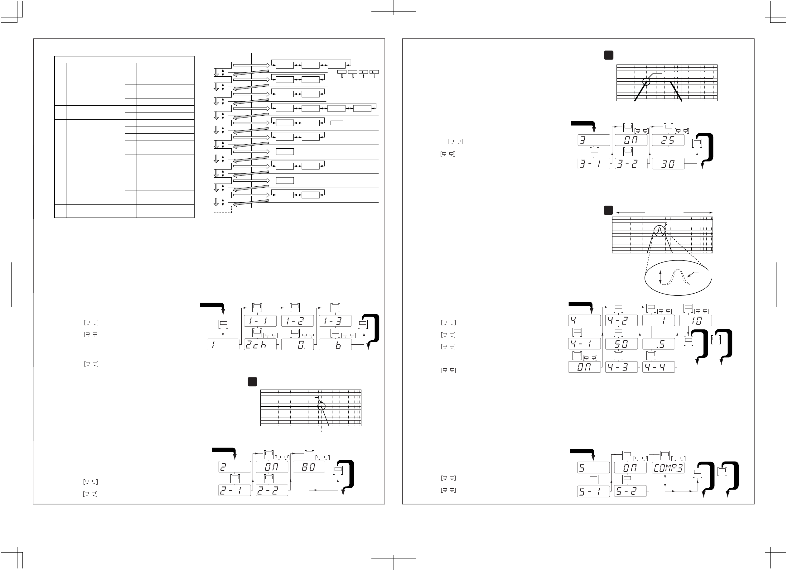
STEP 1. (1) INPUT
Proper configuration of the input setup menu is critical for source signal matching with minimal distortion, while also
optimizing the output level relative to other amplifiers in the system. INPUT SELECT (mode 1-1) should be set
according to the physical input signal connection being made, either “2ch” for stereo or “1ch” for single/mono
channel. INPUT LEVEL (mode 1-2) allows the A/D converter’s input to be optimized for the best possible signal
clarity and volume range. Setting this overly sensitive or severely clipping the input can result in very high distortion,
so it is best to use the clipping indicator as general guide. GAIN FACTOR (mode 1-3) is provided for special cases
where additional gain is still required after all other adjustments have been made. While this signal shaping
algorithm allows a higher average output level to be reached at lower source volumes, signal alteration may not be
desirable in some applications. Therefore, it is recommended to return to this adjustment again later after continuing
through the remaining setup steps.
SETTING THE INPUT
• Push "MODE" to access "1" (INPUT).
• Push "ENT" enter "1". Push "ENT" to enter "1-1" (SELECT).
• Toggle to select "1ch" or "2ch". Push "ENT".
• Push "ENT" to enter "1-2" (INPUT LEVEL).
• Toggle to the input level that will properly match the
source unit output to the amplifier input. Severely clipping the
input will result in high distortion, so use the clipping indicator
as a guide to set this level.
• Push "ENT" to enter "1-3" (GAIN FACTOR). Push "ENT".
• Toggle to select "0", "6" or "9".
• Press "MODE" to advance to step 2 below.
STEP 2. (2) LPF (Low Pass filter)
Eliminating unwanted higher frequencies is essential for optimizing
subwoofer performance and integration with the rest of the system.
Selecting the appropriate cut off frequency of the low pass filter will
depend upon the application, so a wide frequency range (30Hz200Hz) is provided to choose from. Please note however, that if the
selected frequency is very close to or overlaps with the subsonic filter,
it will result in little or no output. Also, if an external crossover is
used, the internal filter can be turned off.
ADJUSTING THE CROSSOVER
• You should be in mode "2" (LPF) now from the
previous step.
• Push "ENT" to enter "2".
• Push "ENT" to enter "2-1" (ON/OFF).
• Toggle to "ON". Push "ENT".
• Push "ENT" to enter "2-2" (FREQUENCY).
• Toggle to desired frequency.
• Push "MODE" to advance to step 3 below.
Copyright 2002 © Alpine Electronics of America, Inc. REV . A-101502
START HERE
MODE MODE
START HERE
ENT
ENT
Lower Frequency (LP) Higher Frequency
1
80Hz Sample Adjustment
0dB
ENT ENT
ENTENT
ENT
ToggleToggle
ENT
dB
20 30 40 6080100K 1000K10Hz
Toggle Toggle
Hz
ENT
ENT
MODE
Toggle
dB
T
O
S
T
E
P
3
STEP 3. (3) SUBSONIC (Subsonic Filter)
Subsonic filters are commonly used to minimize over excursion at
very low frequencies, or to optimize output power by only amplifying
frequencies that can be effectively reproduced. This feature is
essentially a high pass filter with a very low frequency range, and is
selectable from 15Hz to 50Hz in 5Hz increments. Please make sure
that the frequency selected is significantly lower than that of the low
pass filter, unless you have a very specific performance goal in mind.
To the right is example [2], which illustrates the effect of a subsonic
ADJUSTING THE SUBSONIC FILTER
• You should be in mode "3" (SUBSONIC) now from the
previous step.
• Push "ENT" to enter "3". Push "ENT" to enter "3-1" (ON/OFF).
• Toggle to "ON" setting and push "ENT".
• Push "ENT" to enter "3-2" (FREQUENCY).
• Toggle to desired frequency.
• Typical settings include 25Hz for sealed box, and 30Hz
or higher for ported box. (depending on tuning freq.)
• Press "MODE" to advance to step 4 below.
START HERE
STEP 4. (4) PARAMETRIC EQ (Frequency , Width (Q), and Level)
Using the Parametric EQ is a good way to fine tune your
subwoofer or adjust for personal taste. Unlike traditional bass
boost or graphic EQ's, both the center frequency and width of
the EQ band is user selectable, allowing it to be custom tailored
Lower Frequency (LPF) Higher Frequency
2
30Hz Sample Adjustment
0dB
20 30 40 60 100K 1000K10Hz
Toggle Toggle
ENT ENT
Hz
For Sealed
ENTENT
Lower Frequency (LP) Higher Frequency
3
0dB
OR
For Ported
Hz
50Hz Sample Adjustment
MODE
T
O
S
T
E
P
4
for the desired effect. As you can see in example [3], with the
subsonic and low pass filters engaged, you can enhance your
sound by focusing on a high energy bass response in the
20 30 40 60 100K 1000K10Hz
vehicle. When set to its widest setting, this can also function as
ENT
MODE
Variable Width
Adjustment
Toggle
dB
T
O
S
DISP
T
E
OR
P
5
T
O
E
X
I
T
an overall gain adjustment.
NOTE: When adjusting the selected frequency's
width setting, "0.5 or 1" will represent a "WIDE"
SETTING THE PARAMETRIC EQ
• You should be in mode "4" (PARAMETRIC EQ) now
from the previous step.
• Push "ENT" to enter the adjustment menu.
T
O
S
T
E
P
2
• Push "ENT" to enter "4-1" (ON/OFF).
• Toggle to "ON" and push "ENT"
• Push "ENT" to enter "4-2". (FREQUENCY)
• Toggle to desired freq. and push "ENT".
• Push "ENT" to enter "4-3". (WIDTH)
• Toggle to attain the desired width
(note: a lower Q Value= Wider,
a higher Q value = more narrow)
band width and "5" will represent a "NARROW"
bandwidth.
START HERE
ENT ENT
ENTENT
Toggle
ENT ENT
Level
Toggle
For MRD-M300
OR
For MRD-M500
Hz
ENT
• Push "ENT" to enter "4-4". (LEVEL
• Toggle to desired level (boost or cut)
• Press "MODE" to advance to step 5 or "DISP" to exit.
STEP 5. (5) BASS COMP. (Bass Compensation)
Digital Bass Compensation utilizes Alpine’s exclusive
MediaXpander™ processing technology to enhance bass definition
and output. This is an especially useful feature in restoring bass
quality lost with compressed media such as MP3’s. Selection is simply
on/off except for the MRD-M1000, which has three effect levels
available for more precise tuning or personal taste.
SETTING BASS COMPENSATION
• You should be in mode "5" (BASS COMP.) now
from the previous step.
• Push "ENT" and push "ENT" again to select "5-1" (ON/OFF).
• Toggle to "ON". Push "ENT".
• Push "ENT" to enter "5-2" (BASS COMPENSATION LEVEL).
• Toggle to select "COMP.1", "COMP.2" or "COMP.3".
• Press "MODE" to advance to step 6 or "DISP" to exit.
START HERE
ENT
ENT
ENT
Toggle
ENT
Toggle
Mode
T
O
S
T
E
P
6
T
O
E
DISP
X
I
OR
T
To find out more, visit www.alpinetechcenter.com
 Loading...