

Page 1
R
ALPINE ELECTRONICS MARKETING, INC.
1-1-8 Nishi Gotanda,
Shinagawa-ku, Tokyo 141-0031, Japan
Phone 03-5496-8231
ALPINE ELECTRONICS OF AMERICA, INC.
19145 Gramercy Place, Torrance,
California 90501, U.S.A.
Phone 1-800-ALPINE-1 (1-800-257-4631)
ALPINE ELECTRONICS OF CANADA, INC.
7300 Warden Ave., Suite 203, Markham,
Ontario L3R 9Z6, Canada
Phone 1-800-ALPINE-1 (1-800-257-4631)
ALPINE ELECTRONICS OF AUSTRALIA PTY. LTD.
6-8 Fiveways Boulevarde Keysborough,
Victoria 3173, Australia
Phone 03-9769-0000
ALPINE ELECTRONICS GmbH
Frankfurter Ring 117, 80807 München,
Germany
Phone 089-32 42 640
ALPINE ELECTRONICS OF U.K. LTD.
Alpine House
Fletchamstead Highway,
Coventry CV4 9TW, U.K.
Phone 0870-33 33 763
ALPINE ELECTRONICS FRANCE S.A.R.L.
(RCS PONTOISE B 338 101 280)
98, Rue de la Belle Etoile, Z.I. Paris
Nord II, B.P. 50016, 95945 Roissy
Charles de Gaulle Cedex, France
Phone 01-48638989
ALPINE ITALIA S.p.A.
Viale C. Colombo 8,
20090 Trezzano Sul Naviglio (MI), Italy
Phone 02-484781
ALPINE ELECTRONICS DE ESPAÑA, S.A.
Portal de Gamarra 36, Pabellón, 32
01013 Vitoria (Alava) - APDO 133, Spain
Phone 945-283588
TMI-M990
TMI-M990
OWNER'S MANUAL
Sankei Kikaku Co., Ltd.
1-13-38, Hinodai,
Hino, Tokyo, Japan
Designed by ALPINE Japan
Printed in Japan (S)
68-00323Z31-A
Page 2

FOR CAR USE ONLY
• OWNER’S MANUAL
ENGLISH
R
TMI-M990
VGA IN-DASH MONITOR
Please read before using this equipment.
Page 3

Page 4

Contents
Operating Instructions
WARNING
WARNING .............................................. 3
CAUTION ............................................... 4
PRECAUTIONS......................................5
Getting Started
About the Remote Control ...................... 6
About the Indicators and the Microphone ..
Using the TMI-M990 with an IONBUS
connection ............................................. 7
How to Read This Manual.......................8
Basic Operation
Using Face Cover .................................... 9
Initial System Start-up .............................9
Turning Power On or Off ...................... 10
Opening/Closing the Monitor ................ 12
Adjusting the Display Back and Forwards ..
Adjusting the Monitor Viewing Angle ...
Moving the Monitor to be Flat .............. 15
Adjusting the Volume ............................ 15
Switching the Source .............................16
Switching Display Modes ..................... 17
Supplementary information ................... 18
Other Useful Features
About VISUAL EQTM............................ 20
Selecting the
Adjusting and Storing
About REAR SELECTOR .................... 26
Rear Entertainment Function ..............28
Switching the Function of the Remote
Sensor ............................................... 29
Switching the Visual Source Only
(Simultaneous Function) ..................... 30
Blackout Mode On and Off ................... 31
Supplementary information ................... 32
VISUAL EQTM Property .....
VISUAL EQTM.... 23
Setup
About the Setup ..................................... 33
General Setup Operation ....................... 34
Adjusting Brightness .......................... 36
Adjusting Colour of Picture ................ 37
Adjusting Tint of Picture .................... 37
Adjusting Display Contrast ................ 37
7
13
14
21
Adjusting the Sharpness ..................... 38
Storing the Adjusted VISUAL EQ ...... 38
Setting the Illumination Brightness .... 39
Adjusting the Illumination Level ........ 39
Illumination Control ........................... 40
Setting Automatic Opening/Closing
of the Monitor .................................. 40
Selecting the Monitor Opening Angle ...
Adjusting the Monitor Viewing Angle ...
Sound (Beep) Guide Function ............ 41
Changing Lighting Colour ..................42
Navigation Interruption ...................... 42
Navigation Audio Interruption Volume
Adjustment .......................................42
Head Unit Linked Functions ............... 43
AUX IN/S-IN SETUP ........................... 43
Setting the AUX Mode ....................... 45
Name External Equipment to be
Displayed (AUX) .............................45
External Input Audio Level
Adjustment .......................................45
Setting the S-IN Mode ........................ 45
Name the S Video Input to be
Displayed (S-IN) ..............................46
Switching Between NTSC and PAL
Configuration ................................... 46
TV (Optional)
TV operation .......................................... 47
41
41
1-EN
Page 5

Contents
Operating from the Head Unit
Operating from the Head Unit ...............48
Switching the Source .............................49
Adjusting the Volume ............................ 49
Operating the Head Unit with the
Remote Control ................................... 50
Information
In Case of Difficulty ..............................52
Specifications ........................................ 53
Installation and Connections
Warning ................................................. 55
Caution .................................................. 56
Precautions ............................................ 56
Installation ............................................. 57
Connections (TMI-M990 Wiring
Diagram) .............................................60
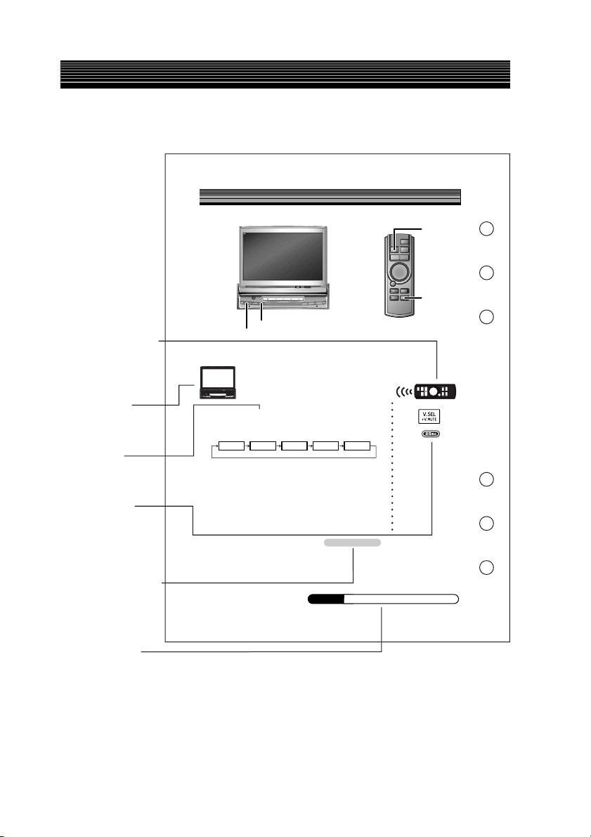
System Example .................................... 62
2-EN
Page 6

WARNING
WARNING
WARNING
This symbol means important
instructions. Failure to heed them
can result in serious injury or death.
DO NOT OPERATE ANY FUNCTION THAT
TAKES YOUR ATTENTION AWAY FROM
SAFELY DRIVING YOUR VEHICLE.
Any function that requires your prolonged
attention should only be performed after
coming to a complete stop. Always stop the
vehicle in a safe location before performing
these functions. Failure to do so may result
in an accident.
KEEP THE VOLUME AT A LEVEL WHERE
YOU CAN STILL HEAR OUTSIDE NOISE
WHILE DRIVING.
Failure to do so may result in an accident.
MINIMIZE DISPLAY VIEWING WHILE
DRIVING.
Viewing the display may distract the driver
from looking ahead of the vehicle and cause
an accident.
DO NOT DISASSEMBLE OR ALTER.
Doing so may result in an accident, fire or
electric shock.
KEEP SMALL OBJECTS SUCH AS
BATTERIES OUT OF THE REACH OF
CHILDREN.
Swallowing them may result in serious
injury. If swallowed, consult a physician
immediately.
USE THE CORRECT AMPERE RATING
WHEN REPLACING FUSES.
Failure to do so may result in fire or electric
shock.
DO NOT BLOCK VENTS OR RADIATOR
PANELS.
Doing so may cause heat to build up inside
and may result in fire.
USE THIS PRODUCT FOR MOBILE 12V
APPLICATIONS.
Use for other than its designed application
may result in fire, electric shock or other
injury.
DO NOT PLACE HANDS, FINGERS OR
FOREIGN OBJECTS IN INSERTION SLOTS
OR GAPS.
Doing so may result in personal injury or
damage to the product.
USE ONLY IN CARS WITH A 12 VOLT
NEGATIVE GROUND.
(Check with your dealer if you are not sure.)
Failure to do so may result in fire, etc.
3-EN
Page 7

WARNING
CAUTION
This symbol means important
instructions. Failure to heed them
can result in injury or material
property damage.
HALT USE IMMEDIATELY IF A PROBLEM
APPEARS.
Failure to do so may cause personal injury or
damage to the product. Return it to your
authorized Alpine dealer or the nearest
Alpine Service Centre for repairing.
DO NOT MIX NEW BATTERIES WITH OLD
BATTERIES. INSERT WITH THE CORRECT
BATTERY POLARITY.
When inserting the batteries, be sure to
observe proper polarity (+ and –) as
instructed. Rupture or chemical leakage from
the battery may cause fire or personal injury.
KEEP FINGERS AWAY WHILE THE
MOTORIZED FRONT PANEL OR MOVING
MONITOR IS IN MOTION.
Failure to do so may result in personal injury
or damage to the product.
4-EN
Page 8

PRECAUTIONS
Product Cleaning
Use a soft dry cloth for periodic cleaning of
the product. For more severe stains, please
dampen the cloth with water only. Anything
else has the chance of dissolving the paint or
damaging the plastic.
Temperature
Be sure the temperature inside the vehicle is
between +45°C (+113°F) and 0°C (+32°F)
before turning your unit on.
Moisture Condensation
You may notice the disc playback sound
wavering due to condensation. If this
happens, remove the disc from the player and
wait about an hour for the moisture to
evaporate.
Maintenance
If you have problems, do not attempt to
repair the unit yourself. Return it to your
Alpine dealer or the nearest Alpine Service
Station for servicing.
Remove the anti-theft cover when you drive.
This prevents the cover from falling off the
unit and interfering with the safe operation of
the vehicle.
Operation of some of the functions of this
unit is very complex. Because of this, it was
deemed necessary to place these functions
into a special screen. This will restrict
operation of these functions to times when
the vehicle is parked. This ensures the focus
of the driver's attention will be on the road
and not on the TMI-M990. This has been
done for the safety of the driver and
passengers.
The Setup operation cannot be performed if
the car is moving. The car must be parked
and the parking brake must be engaged for
the procedure described in the Owner's
Manual to be valid. The warning “CAN'T
OPERATE WHILE DRIVING,” will be
displayed if any attempts are made to
perform these operations while driving.
This operation is the same as when selecting
sources using the remote control. When the
car is parked, the selection is made as
described in the Owner's Manual.
Installation Location
Make sure the TMI-M990 will not be
installed in a location subjected to:
• Direct sun and heat
• High humidity and water
• Excessive dust
• Excessive vibrations
• After turning the system off, a slight ghost
of the image will remain temporarily. This
is an effect peculiar to LCD technology
and is normal.
• In cold temperature conditions, the screen
may lose contrast temporarily. After a
short warm-up period, it will return to
normal.
5-EN
Page 9
Getting Started
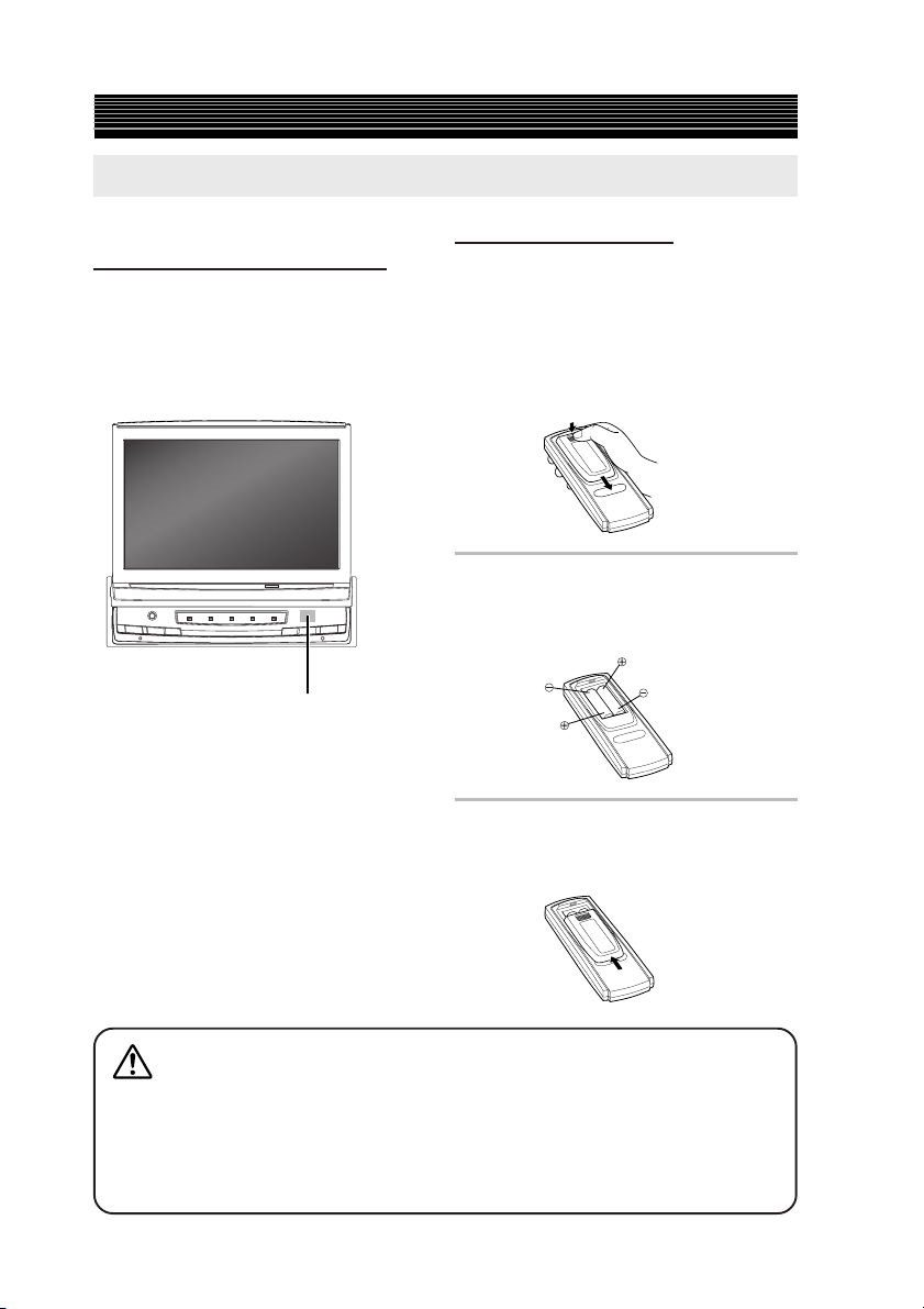
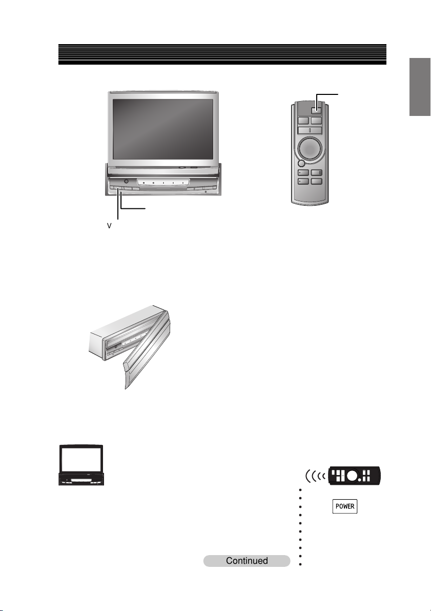
About the Remote Control
Notes on Using the Remote
Controlmmmmmmmmmmm
Point the remote control transmitter at the
remote control sensor.
If connected to an IONBUS compatible head
unit, even if you point the remote control at the
remote control sensor on the head unit, the
operation is received the same way.
Remote control sensor
• Point the remote control at the remote sensor
within about 2 meters.
• It may not be possible to operate the remote
control unit if the remote control sensor is
exposed to direct sunlight.
• The remote control is a small, light weight
precision device. To avoid damage, short
battery life, operational errors and poor
button response, observe the following.
− Do not subject to shock.
− Do not put in a trouser pocket.
− Keep away from food, moisture and dirt.
− Do not place in direct sunlight.
Battery Replacement
Applicable battery: Use two “AAA” sized dry
batteries or equivalent.
1 Opening the battery cover.
Push on the cover and slide it as
indicated by the arrows then the
cover will be removed.
2 Replacing the battery.
Put the batteries in the case
observing the polarity, as illustrated.
3 Closing the cover.
Push the cover in the arrow
direction until a click is heard.
Warning
DO NOT OPERATE ANY FUNCTION THAT TAKES YOUR ATTENTION AWAY
FROM SAFELY DRIVING YOUR VEHICLE.
Any function that requires your prolonged attention should only be performed after
coming to a complete stop. Always stop the vehicle in a safe location before performing
these functions. Failure to do so may result in an accident.
6-EN
Page 10
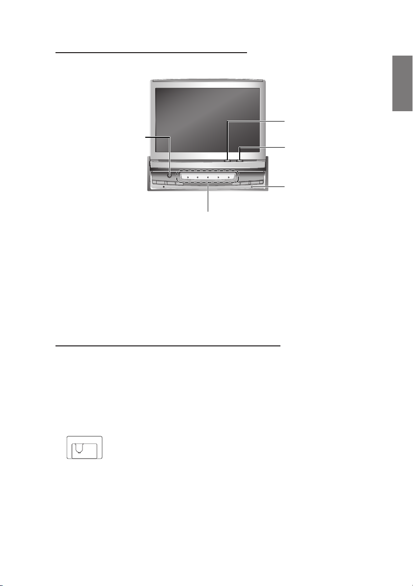
About the Indicators and the Microphone
Display indicators
Road EQ microphone
(When Multimedia
Manager, PXI-H990
is connected)
One of the functions of the
Road EQ is a microphone
when connected to the
Multimedia Manager
(PXI-H990) (sold separately).
For more information,
refer to the PXI-H990
Operating Instructions.
*1When AUTO is set for the “Illumination Control” (page 40), the light level corresponds to the
detection of the Brightness sensor. So, when the ambient is dark, the indicator may not be lit.
*2You can set the colour and brightness to your desired level.
(Refer to “Setting the Illumination Brightness” on page 39, “Changing Lighting Colour” on page
42.)
Input indicator
The selected source indicator
is a different colour than other
sources (the colour is different
depending on the settings).
2
*
Lit when the display is on.
Brightness sensor
Detects the ambient
light level.
Action indicator
Flashes when the
display opens and
shuts.
Using the TMI-M990 with an IONBUS connection
This unit connects to IONBUS compatible head units, and can even be operated from the head unit.
• For more information for operating from the head unit, refer to Operating from the Head Unit
page 48-51.
• To connect and use the IONBUS, turn the system switch on the main unit to “SYSTEM”. (See
page 58).
1
*
System switch
1:SYSTEM
2:STANDALONE
12
(Initial Setting)
7-EN
Page 11
Getting Started
How to Read This Manual
This manual details how to operate the TMI-M990 and the supplied remote control RUE-4199.
Basic Operation
V.SEL/
V.MUTE
WIDE/
R.SEL
R.SEL/WIDE
Remote control icon
Indicates operations
performed with the
remote control unit.
V.SEL/DISP.OFF
Switching the Source
Main unit icon
Indicates operations
performed on the
main unit.
Button name
Buttons to be
operated are
indicated in bold.
1Sec/2Sec icon
Indicates that the
specified remote
control button
should be pressed
and held for over
1 or 2 seconds.
Continued (Next page)
Indicates that the
description of the
operation continues
on the next page.
Supplement icon
Indicates that there is
supplementary information
on another page.
8-EN
1
Press V.SEL/DISP.OFF.
Each press of the button will cycle through the
modes as follows:
• AUX-1, 2, 3 is only displayed when AUX IN 1, 2, 3 SIG. is
• DVD displays when S-IN SIG. is set to ON.
When connected with an IONBUS compatible head unit:
• The picture source can be switched from the head unit. For
16
-
AUX-1
NAVI.
ON. For details, refer to “Setting the AUX Mode”, page 45.
For details, see “Setting the S-IN Mode”, page 45.
details, see Operating from the Head Unit “Switching the
Source”, page 49.
Supplement
EN
AUX-2 AUX-3 DVD
Supplement
Continued
See page 19 for supplementary infor
mation.
Page 12
Basic Operation
Reset switch
V.SEL/DISP.OFF
Using Face Cover
An anti-theft face cover is provided with the TMI-M990.
Put the face cover onto the TMI-M990 when you leave the vehicle.
Be sure to remove the anti-theft face cover when you drive.
POWER
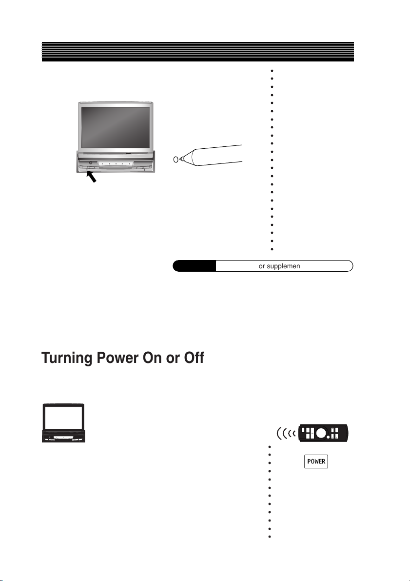
Initial System Start-up
Immediately after installing or applying power to the unit, it should be initialized.
○○○○○○○○○○
1 Check that the power is switched off.
If it is on, press and hold V.SEL/DISP.OFF for more
than 2 seconds to switch off the power.
Continued
9-EN
Page 13
Basic Operation
2 Press the reset switch with the tip of a pen.
• To switch off the power on an IONBUS compatible head
unit when it is connected:
When the head unit power is switched off, the TMI-M990
power is also switched off. The power cannot be switched off
from the TMI-M990.
○○○○○○○○○○○○○○○○○○○○○○○
Supplement
See page 18 for supplementary information.
Turning Power On or Off
Some of this unit's functions cannot be performed while the vehicle is in motion. Be sure to stop
your vehicle in a safe location and apply the parking brake, before attempting these operations.
○○○○○○○○○○○○
1 Press V.SEL/DISP.OFF to turn on the unit.
10-EN
Page 14
2 Press and hold V.SEL/DISP.OFF for at least 2
seconds to turn off the unit.
• The unit can be turned on by pressing any one of the buttons
V.SEL/DISP. OFF, VISUAL EQ or R.SEL/WIDE.
• The TMI-M990 draws minimal current even when its power
switch is turned off. If the switched power (ignition) lead of the
TMI-M990 is connected directly to the positive (+) post of the
vehicle's battery, the battery may be discharged. If this lead is
unswitched, it must be disconnected from the battery post
should the vehicle be left unused for an extended period of
time.
An SPST (Single-Pole, Single-Throw) switch (sold separately)
can be added to simplify this procedure. Then, you can simply
place it in the OFF position when you leave the vehicle. Turn
the SPST switch back ON before using the TMI-M990. For
connecting the SPST switch, refer to the “Connection Diagram
of SPST Switch” (page 59).
• Some operation of the unit cannot be performed while the
vehicle is in motion. In this case, be sure to first stop your
vehicle and apply the parking brake, then perform the
operation.
When the TMI-M990 is connected to an IONBUS compatible
head unit:
• The TMI-M990 power is linked to the head unit. When the
head unit is switched on, the TMI-M990 is also switched on,
and when the head unit is switched off, the TMI-M990 is also
switched off.
For details, refer to the head unit Operating Instructions.
• The power cannot be switched off from the TMI-M990.
• When the system switch on this unit is set to STANDALONE,
the power will not turn on. You must set to SYSTEM. (See
page 58)
Supplement
See page 18 for supplementary information.
○○○○○○○○○○○○○○○○○○○○○○○○○○○○○○○○○○○○○○○○
11-EN
Page 15
Basic Operation
BAND/
SETUP
/O/C
/FLAT
/TILT
/TILT
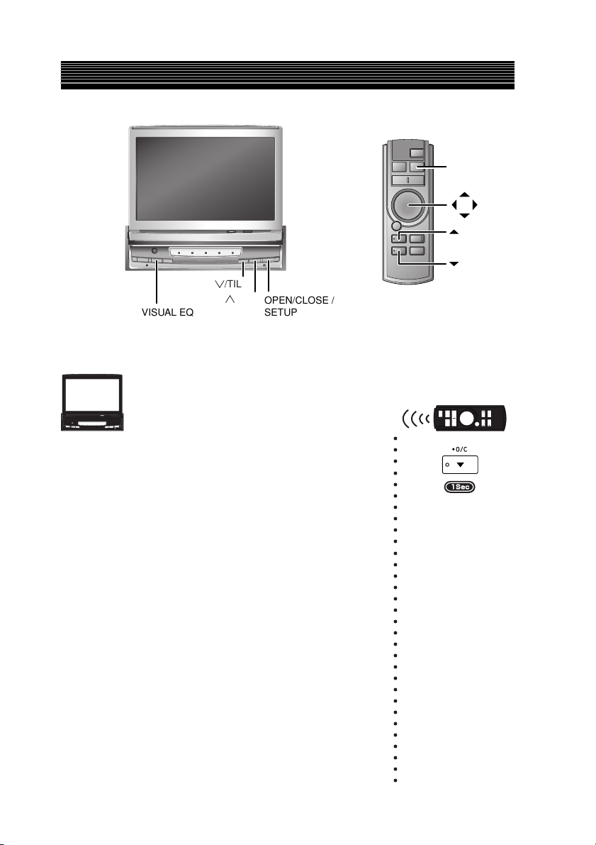
VISUAL EQ
Opening/Closing the Monitor
1 Press OPEN/CLOSE / SETUP.
The unit beeps 3 times and raises (or lowers) the
monitor automatically.
OPEN/CLOSE /
SETUP
○○○○○○○○○○○○○○○○○○○○○○○○○○○○○○○
• The TMI-M990 is a precision device. With gentle handling, its
unique capabilities can be enjoyed for a long time.
• When the movable monitor is opened, do not place any object
on the monitor and be careful not to bump or apply any
pressure to the monitor while it is open. This can cause damage
to the mechanism.
• For your safety, some operation of the unit cannot be performed while the vehicle is in motion. In this case, first stop the
vehicle and engage the parking brake, then perform the
operation.
• If there is something in the way when opening the display, the
display stops immediately. When this happens, remove the
obstruction and press OPEN/CLOSE / SETUP again.
• If there is something in the way when closing the display, the
display stops immediately. When this happens, remove the
obstruction and press OPEN/CLOSE / SETUP again.
12-EN
Page 16
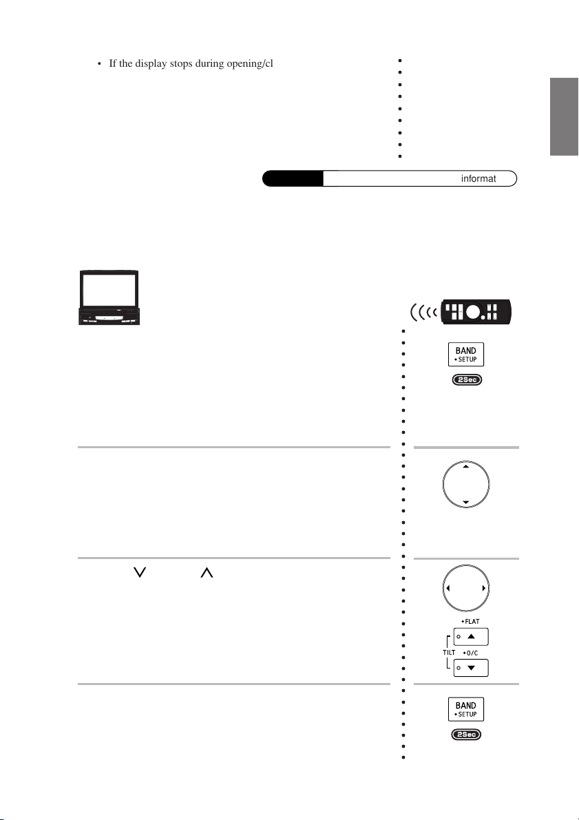
• If the display stops during opening/closing, then press OPEN/
CLOSE / SETUP again. If it still does not move, then contact
your Alpine dealer. Do not force the display. You may damage
your TMI-M990.
• The display activates using the values stored for angle
adjustment and back and forward adjustment.
See “Adjusting the Display Back and Forwards” (this page),
and “Adjusting the Monitor Viewing Angle” (page 14).
Supplement
See page 18 for supplementary information.
○○○○○○○○○
Adjusting the Display Back and Forwards
The monitor opening angle can be set in 2 positions.
○○○○○○○○○○○○○○○○○○○○○○○○○○○○○○○○○○○○○○○
1 Press and hold OPEN/CLOSE / SETUP for at least 2
seconds while the display is out.
2 Press OPEN/CLOSE / SETUP or VISUAL EQ and
select SLIDE.
When you press OPEN/CLOSE / SETUP, you move
to the next item, press VISUAL EQ to move to the
previous item.
3 Press / TILT or / TILT, and select BACK or
FRONT.
The display can slide about 1 cm back and forwards.
4 When you have finished adjusting, press and hold
OPEN/CLOSE / SETUP for at least 2 seconds.
13-EN
Page 17
Basic Operation
/TILT
/TILT
Adjusting the Monitor Viewing Angle
Adjust the monitor's angle for better visibility.
○○○○○○○○○○○○○○○○○○○○○
1 Press / TILT and / TILT to adjust the monitor's
angle so the screen will be in the best viewing
position.
Pressing the buttons changes the screen angle
between about 40 and 105 degrees.
/VOLUME
/VOLUME
/FLAT
/TILT
/O/C
/TILT
• By pressing and holding / TILT or / TILT, the angle
changes continuously.
• You can also adjust the display angle by selecting from one of
10 levels.
For details, see the Setup operation “Adjusting the Monitor
Viewing Angle” on page 41
• The adjustment angle is stored, but depending on the motion,
the position can be a shifted from the original position.
Supplement
See page 19 for supplementary information.
See page 19 for supplementary information.
14-EN
Page 18
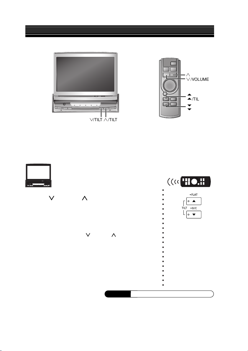
Moving the Monitor to be Flat
When you want to operate some function on the car (air conditioner, etc.) which is hidden by the
raised monitor, use this function.
The following operation is performed with the supplied
remote control.
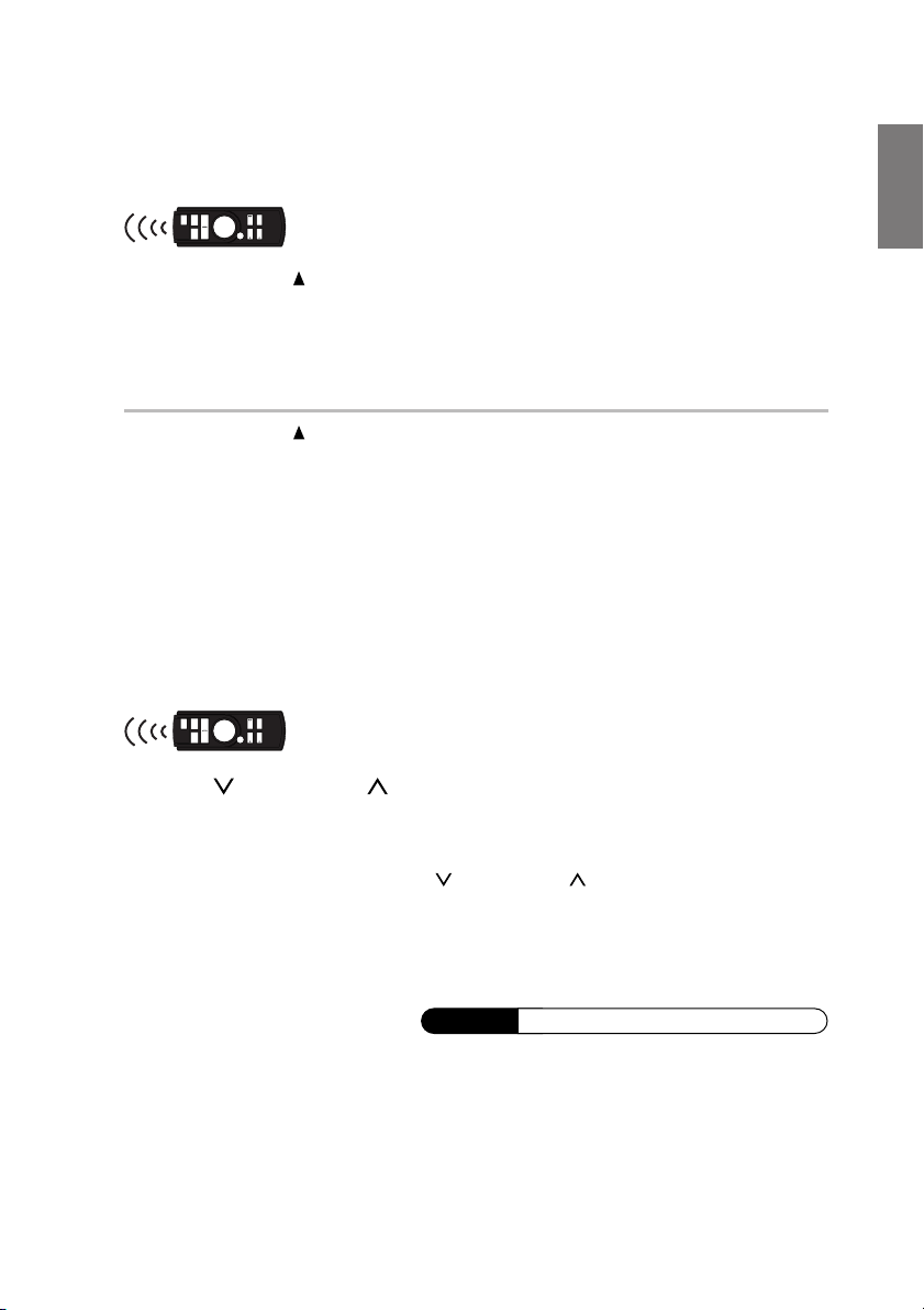
1 Press and hold /FLAT for at least 2 secondes.
The monitor moves to the flat position.
2 Press and hold /FLAT again for at least 2 secondes.
The monitor returns to the previous angle.
• The monitor returns to the previous angle from being flat after 10 seconds.
• If an excessive force is added to the monitor when the monitor is flat, putting an object on
the back of the monitor for example, it may cause a malfunction.
Adjusting the Volume
The following operation is performed with the supplied
remote control.
1 Press / VOLUME or / VOLUME to adjust the volume.
Adjust the volume output to the Amplified Speaker that is connected to the
AUX Audio Output (AUX OUT 1) Terminal.
• The volume changes continuously if / VOLUME or / VOLUME is held down.
• You can adjust the volume level for each source.
When connected with an IONBUS compatible head unit:
• The volume adjustment is performed at the head unit. For details, see Operating from the
Head Unit “Adjusting the Volume”, page 49.
Supplement
See page 19 for supplementary information.
15-EN
Page 19
Basic Operation
WIDE/
R.SEL
V.SEL/
V.MUTE
R.SEL/WIDE
V.SEL/DISP.OFF
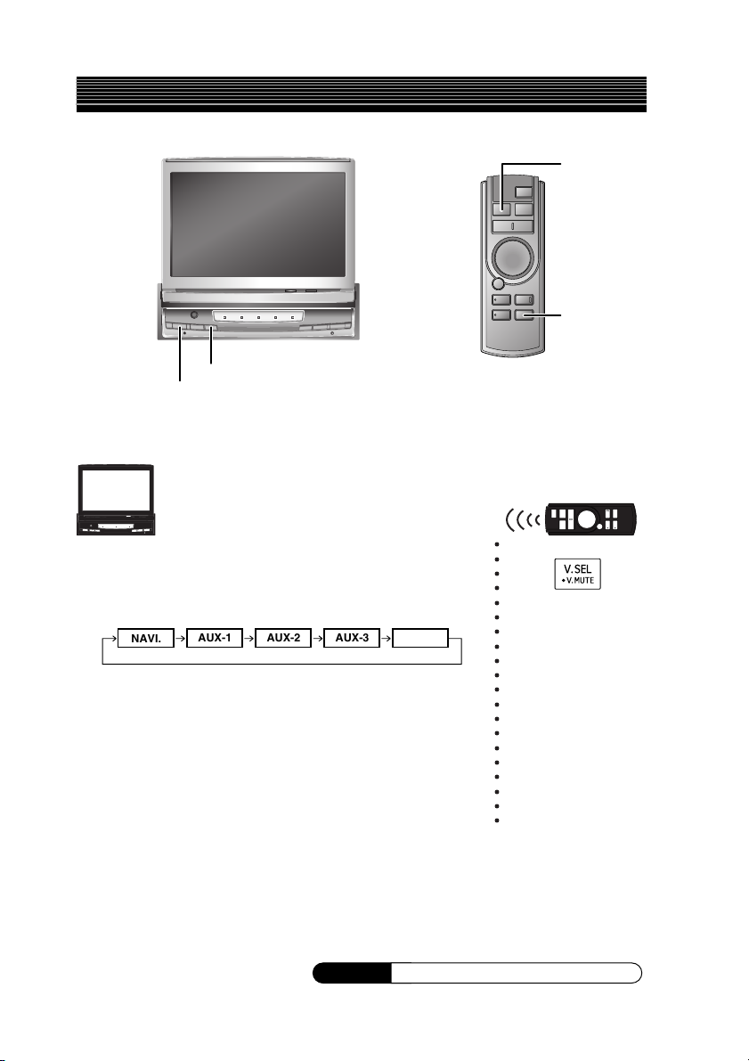
Switching the Source
1 Press V.SEL/DISP.OFF.
Each press of the button will cycle through the
modes as follows:
NAVI.
AUX-1
AUX-2 AUX-3 DVD
○○○○○○○○○○○○○○○○○○○○
• AUX-1, 2, 3 is only displayed when AUX IN 1, 2, 3 SIG. is
ON. For details, refer to “Setting the AUX Mode”, page 45.
• DVD displays when S-IN SIG. is set to ON.
For details, see “Setting the S-IN Mode”, page 45.
When connected with an IONBUS compatible head unit:
• The picture source can be switched from the head unit. For
details, see Operating from the Head Unit “Switching the
Source”, page 49.
Supplement
Supplement
16-EN
See page 19 for supplementary information.
Page 20
Switching Display Modes
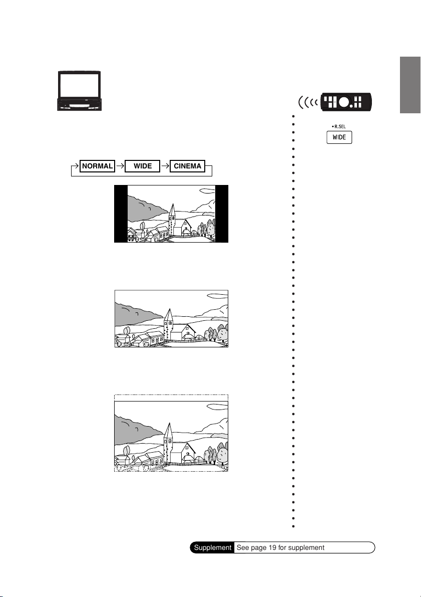
1 Press and hold R.SEL/WIDE for at least 2 seconds in
the visual source.
Each press changes the display modes as follows:
NORMAL WIDE CINEMA
In Normal mode, the monitor displays a normal
picture at the centre of the screen with a vertical
black band at each side.
○○○○○○○○○○○○○○○○○○○○○○○○○○○○○○○○○○○○○○○○○○○○○○○○○○○○
In Wide mode, the monitor displays a normal picture
wider to fit in a wide-screen monitor by evenly
stretching out the picture horizontally.
In Cinema mode, the monitor displays a normal
picture by stretching out the picture horizontally and
vertically. This mode is good for displaying a cinema
type picture at the 16 : 9 ratio.
Supplement
See page 19 for supplementary information.
17-EN
Page 21
Basic Operation
Supplementary
information
TITLE
Initial System Startup
Turning Power On
or Off
Opening/Closing
the Monitor
This page includes supplementary information for pages 9 to 17.
Please refer to these pages.
Description
When reset, the stored contents are lost. Perform storage
and adjustment one more time.
If you reset when the display is open, then the display is
automatically closed.
If you reset while the display is opening , the backlight
briefly lights up, but this is not a fault.
The power does not switch off by simply closing the display.
The TMI-M990 stores the state before the ignition key
switches off. For example, if the ignition key is switched
from OFF to ON in NAVI. mode, then the NAVI. mode is
activated.
If OPEN/CLOSE / SETUP is pressed while the display is
moving, then it stops. When it stops, press OPEN/CLOSE /
SETUP again.
The display automatically opens/closes depending on the
status of the ignition key (engine key). For the setup
operation, “Setting Automatic Opening/Closing of the
Monitor”, page 40.
The display can be opened even when the power is off, but
the power will not automatically turn on.
See “Turning Power On or Off” (page 10) to turn on the
power.
Under cold temperature conditions, the screen may lose
contrast temporarily. After a short warm-up period, it will
return to normal.
In low ambient temperature conditions, the display may be
dark for a short period of time immediately after the power
is turned on. Once the LCD has warmed up, the display
returns to normal.
Related page
Page 9
Page 9
Page 9
Page 10
Page 10
Page 12
Page 12
Page 12
Page 12
Page 12
18-EN
Page 22
TITLE
Adjusting the
Monitor Viewing
Angle
Adjusting the
Volume
Switching the
Source
Switching Display
Modes
Description
If the monitor touches an obstacle while the angle is being
adjusted, the unit stops the screen immediately.
Should this happen, remove the obstacle and press
/ TILT or / TILT again.
The screen color will vary when viewed at certain angles.
Adjust the screen angle for the best viewing position.
If the voltage of the vehicle's battery power is low, the
screen may blink when the screen angle is changed. This is
normal and not a malfunction.
The display angle is also allowed to adjust while turning
power off.
The factory settings for the sound volume is minimum.
In the AUX mode, if you press BAND/SETUP on the
supplied remote control, you can change between AUX-1,
2, 3.
AUX-1 AUX-2 AUX-3
In the setup screen, etc., the display mode enters Wide
mode.
After exiting from the setup operation, the display mode
returns to the original display mode.
In the navigation screen, the display mode is not allowed to
be switched.
Related page
Page 14
Page 14
Page 14
Page 14
Page 15
Page16
Page17
Page17
19-EN
Page 23

Other Useful Features
/TILT
/TILT
VISUAL EQ
OPEN/CLOSE /
SETUP
/FLAT
V.EQ
/O/C
About VISUAL EQ
The Parking Brake must be engaged to access the Setup screen. Attempting to access this screen
while driving will display the warning – CAN'T OPERATE WHILE DRIVING.
Use VISUAL EQ to create the best image by compensating for the ambient light conditions, then
store your settings on the TMI-M990.
TM
○○○○○○○○○○○○○○○○○○○○○○○○○○○○○
1 Select VISUAL EQ ON mode by pressing VISUAL
EQ.
VISUAL EQ ON OFF
<Example of VISUAL EQ ON screen>
LINK
AUX-1
When switched ON, the selected VISUAL EQ
property name is displayed.
•“OFF” is set on this unit when the power is turned on. Press
VISUAL EQ to display “FLAT”.
20-EN
Page 24

2 Press and hold VISUAL EQ for at least 2 seconds.
The VISUAL EQ SETUP screen is displayed, and
various VISUAL EQ settings can be made.
<Example of VISUAL
EQ SETUP screen>
○○○○○○○○○○○○○○○○○○○○○○○○○
3 To exit VISUAL EQ SETUP, press and hold VISUAL
EQ for more than 2 seconds.
The screen returus to normal mode.
• If you select OFF in step 1, then VISUAL EQ settings etc.
cannot be performed.
Selecting the VISUAL EQTM Property
1 Select VISUAL EQ ON mode by pressing VISUAL
EQ.
VISUAL EQ ON OFF
• When VISUAL EQ is ON, the selected VISUAL EQ property
name is displayed. (See page 20)
•“OFF” is set on this unit when the power is turned on. Press
VISUAL EQ to display “FLAT”.
2 Press and hold VISUAL EQ for at least 2 seconds.
The VISUAL EQ SETUP screen is displayed.
3 Press OPEN/CLOSE / SETUP and select VISUAL
EQ.
Continued
○○○○○○○○○○○○○○○○○○○○○○○○
21-EN
Page 25

Other Useful Features
4 Select your preferred VISUAL EQ property with either
/ TILT or / TILT.
FLAT
USER1/2
FLAT: Flat image.
NIGHT MOVIE: Brightens up a dark scene. Suitable
SOFT: Suppresses screen glare. Suitable
SHARP: Sharpens the picture. Suitable when
HIGH CONTRAST
USER 1/2: Accesses the adjustment value
NIGHT MOVIE
HIGH CONTRAST
for movies with a lot of dark scenes.
when watching CG or animation.
the picture is not clear.
:Increases the screen contrast.
Suitable for new movies.
stored in “Adjusting and Storing
VISUAL EQ
5 Press and hold VISUAL EQ for at least 2 seconds.
The screen returns to normal mode.
• You can set VISUAL EQ for each picture source such as DVD.
(VISUAL EQ cannot be set in RGB navigation mode, backup
camera interruption mode.)
SOFT
SHARP
TM
” (page 23).
○○○○○○○○○○○○○○○○○○○○○○○○○○○○○○○○○○
22-EN
Page 26

VISUAL EQ
V.SEL/DISP.OFF
/TILT
/TILT
OPEN/CLOSE /
SETUP
V.SEL
V.MUTE
/FLAT
V.EQ
/O/C
Adjusting and Storing VISUAL EQ
You can store up to two of your image adjustments. The picture brightness, colour, tint, contrast and
sharpness can be adjusted.
TM
○○○○○○○○○○○○○○○○○○○○○○○○○○○○
1 Press VISUAL EQ to select the VISUAL EQ ON
mode.
VISUAL EQ ON OFF
• When VISUAL EQ is ON, the selected VISUAL EQ property
name is displayed. (See page 20)
•“OFF” is set on this unit when the power is first turned on.
Press VISUAL EQ to display “FLAT”.
2 Press and hold VISUAL EQ for at least 2 seconds.
The VISUAL EQ SETUP screen is displayed.
Continued
23-EN
Page 27

Other Useful Features
3 Press OPEN/CLOSE / SETUP or VISUAL EQ, and
select an item to adjust from BRIGHT, COLOR, TINT,
CONTRAST, SHARPNESS.
When you press OPEN/CLOSE / SETUP, you move
to the next item, press VISUAL EQ to move to the
previous item.
• For details on each item, see the General Setup Operation
“Adjusting Brightness”, “Adjusting Colour of Picture”,
“Adjusting Tint of Picture”, “Adjusting Display Contrast”,
“Adjusting the Sharpness” (page 36 to 38).
4 Adjust the selected item by pressing / TILT or
/ TILT.
5 When adjusting another item, repeat steps 3 and 4.
○○○○○○○○○○○○○○○○○○○○○○○○○○○○○○○○○○○○○○○○○○○○○○○○○○○○○○○○○○○○
6 When the picture settings are complete, press
OPEN/CLOSE / SETUP or VISUAL EQ and select
V.EQ MEMORY.
When you press OPEN/CLOSE / SETUP, you move
to the next item, press VISUAL EQ to move to the
previous item.
7 Select the USER1 or USER2 mode by pressing
/ TILT or / TILT.
CUSTOM is displayed
while adjusting.
USER1 or USER2 mode.
24-EN
Page 28

8 Press V.SEL/DISP.OFF.
The stored adjustments are applied to the current
video image.
9 After setting, press and hold VISUAL EQ for at least
2 seconds.
The screen returns to the previous one.
• To recall the stored adjustment values, see “Selecting the
VISUAL EQTM Property” (page 21).
• After selecting the manufacturer’s setting of VISUAL EQ
property (NIGHT MOVIE etc.), the property can be adjusted
and saved. While adjusting, CUSTOM is displayed.
○○○○○○○○○○○○○○○○○○○○○○
Supplement
See page 32 for supplementary information.
25-EN
Page 29

Other Useful Features
WIDE/R.SEL
DISP/A.MEMO
/O/C
/FLAT
R.SEL/
WIDE
VISUAL EQ
/TILT OPEN/CLOSE/
SETUP
/TILT
About REAR SELECTOR
With a Rear monitor connected to the TMI-M990, its adjustments may be set using the REAR
SELECTOR screen. The following steps 1 to 4 are common operations for the REAR SELECTOR
screen. Refer to each section for details.
< REAR SELECTOR standard operation >
○○○○○○○○○○○○○○○○○○○○○○○○
1 Press R.SEL/WIDE.
The screen changes to the REAR SELECTOR
screen.
26-EN
Page 30

2 Press OPEN/CLOSE / SETUP or VISUAL EQ and
select the item to set.
When you press OPEN/CLOSE / SETUP, you move
to the next item, press VISUAL EQ to move to the
previous item.
3 Change the setting item by pressing / TILT or
/ TILT.
4 After setting, press R.SEL/WIDE.
The screen returns to the previous one.
○○○○○○○○○○○○○○○○○○○○○○○○○○○○○○○○○○○○○○○○○○○○○○○○○○○○○○○
Rear monitor 1 (AUX OUT1),
Rear monitor 2 (AUX OUT2)
status display. (See page 28)
Remote control output display
When rear monitor remote control
operation is valid,
played. (See page 29)
(See page 29)
• When you press DISP./A.MEMO on the remote control unit, the
current status is displayed.
The displayed items are the source (page 16), the display modes
(page 17) and the VISUAL EQ property (page 21) other than the
rear monitor status.
indicator is dis-
Supplement
See page 32 for supplementary information.
27-EN
Page 31

Other Useful Features
Rear Entertainment function
The Rear Entertainment function independently routes different sources to the front and the rear of
the car. For example, while listening to the radio or other audio source in the front, DVD can be
enjoyed in the rear with the optional rear monitor and headphones.
Setting item: AUX OUT1, AUX OUT2
AUX OUT1*1: Select the source, from the list below, that is
output to AUX OUT1.
AUX OUT2: Select the source, from the list below, that is
output to AUX OUT2.
Setting content:
LINK, NAVI., AUX-1, AUX-2, AUX-3, DVD
LINK: The picture and sound being shown on the TMI-M990
is output to the rear monitor.
NAVI.: The picture and sound from the Navigation is output to
the rear monitor. (Only when the Navigation is
connected)
AUX-1*
AUX-2*
AUX-3*
DVD *
2
: Any A/V source unit (TV, VCR, Video Game, etc.)
2
: Any A/V source unit (TV, VCR, Video Game, etc.)
2
: Any A/V source unit (TV, VCR, Video Game, etc.)
3
: The picture from the S video output compatible
Alpine head unit is output to the rear monitor.
1
*
If not connected to an IONBUS compatible head unit, AUX
OUT1 is fixed to LINK. It is then used as audio output for the
front (TMI-M990).
2
*
Only displayed when AUX IN 1, 2, 3 SIG. ON (See page 45).
3
*
Only displayed when S-IN SIG. ON (See page 45).
28-EN
Page 32

Switching the Function of the Remote Sensor
The remote sensors of the external unit (monitor, etc.), can be selected for Remote control operation
from the external unit.
Setting item: REM.CON IN
Setting content:
FRONT, REAR-1, REAR-2
FRONT: The remote control sensor on the main unit is
enabled. Remote control operation from any
external monitor is disabled.
REAR-1*
REAR-2: The remote sensor of the external monitor
*4Can be set only when an IONBUS compatible head unit is connected.
• When set to REAR-1/2, remote control operation cannot be
4
: The remote sensor of the external monitor
connected to AUX OUT1 is enabled. Remote
control operation of the source selected for AUX
OUT1 only, is possible.
connected to AUX OUT2 is enabled. Remote
control operation of the source selected for AUX
OUT2 only, is possible.
performed on the FRONT (TMI-M990). In this case, perform
operation with the buttons of the TMI-M990 main unit.
29-EN
Page 33

Other Useful Features
V.SEL/
V.MUTE
V.SEL/DISP.OFF
Switching the Visual Source Only
(Simultaneous Function)
When an IONBUS compatible head unit is connected, you can watch the video portion of another
source while listening to the current source.
On the TMI-M990, you can watch video from the AUX or NAVI. while listening to the FM, AM or
a CD on the head unit.
1 Change to your preferred source (FM, AM, CD etc.)
on the head unit.
For details, see the head unit operating instructions.
2 Press V.SEL/DISP.OFF.
The TMI-M990 picture source changes each time it is
pressed.
<Example>
(Picture)
(Audio)
AUX-3
DVD
* When simultaneous is off.
DVD
DVD
*
AUX-2
DVD
NAVI.
DVD
AUX-1
DVD
30-EN
○○○○○○○○○○○○○○○○○○○○○○○
Page 34

• The simultaneous function can only be used when an IONBUS
compatible head unit is connected.
• To output the AUX, NAVI. mode sound of TMI-M990 during
simultaneous operation, change the head unit source to AUX,
NAVI. mode. See (Operating from the Head Unit. “Switching the Source”, page 49).
• When the simultaneous function is active and you change the
head unit source, only the audio is switched and the simultaneous function is not cleared. To clear the simultaneous function,
press V.SEL/DISP.OFF on the main unit to switch to video
and audio from the same source.
The simultaneous function can also be cleared by linking to
when the DVI-9990R/DVI-9990E source switches. (General
Setup Operation “Head Unit Linked Functions” page 43)
○○○○○○○○○○○○○○○○
Blackout Mode On and Off
When Blackout mode is turned on, the display will turn off. The backlight life can be extended.
The following operation is performed with the supplied
remote control.
1
Press and hold V.SEL/V.MUTE for at least 2 seconds to start the blackout mode.
By doing so the display will turn off.
2 To cancel Blackout mode, press and hold V.SEL/V.MUTE for at least 2
seconds.
• If any button on the unit is pressed during Blackout mode, the function will be displayed for
5 seconds to show the operation before returning to Blackout mode.
[When an IONBUS Compatible Head Unit is Connected]
Operation can be performed with either the main unit switch
or the remote control. The main unit switch operation is as
follows.
1 Press and hold V.SEL/DISP.OFF for at least 2 seconds to start the blackout
mode.
By doing so the display will turn off.
2 To cancel Blackout mode, press and hold V.SEL/DISP.OFF for at least 2
seconds.
• If any button on the unit is pressed during Blackout mode, the function will be displayed for
5 seconds to show the operation before returning to Blackout mode.
Supplement
See page 32 for supplementary information.
31-EN
Page 35

Other Useful Features
Supplementary
information
TITLE
Adjusting and
Storing VISUAL EQ
About REAR
SELECTOR
Blackout Mode On
and Off
This page includes supplementary information for pages 20 to 31.
Please refer to these pages.
Description
Adjusting and storing of VISUAL EQ can also be made
from the setup. The procedure is below. For more details,
see the General Setup Operation.
Operation from the main unit
1 Press and hold OPEN/CLOSE / SETUP for at least 2
seconds.
2 Press VISUAL EQ or OPEN/CLOSE / SETUP, and
select an item to adjust from BRIGHT, COLOR, TINT,
CONTRAST, SHARPNESS.
3 Adjust the image by pressing
4 When adjusting another item, repeat steps 2 and 3.
5 When the picture settings are complete, press VISUAL
EQ or OPEN/CLOSE / SETUP and select V.EQ
MEMORY.
6 Press
7 Press V.SEL/DISP.OFF.
8 After setting, press and hold OPEN/CLOSE / SETUP for
Operation from the remote control
1 Press and hold BAND/SETUP for at least 2 seconds.
2 Press
3 Adjust the image by pressing
4 When adjusting another item, repeat steps 2 and 3.
5 When the picture settings are complete, press
6 Press
7 Press V.SEL/V.MUTE.
8 After setting, press and hold BAND/SETUP for at least 2
The REAR SELECTOR function which switches the source
of the rear monitor is allowed to set while driving.
When using the head unit BLACK OUT function, the main
unit switch and the input indicator illumination turn off.
/ TILT or / TILT to select USER1 or USER2
mode.
The image adjustments are stored in the selected mode.
at least 2 seconds. The screen returns to the previous
one.
or , and select an item to adjust from
BRIGHT, COLOR, TINT, CONTRAST, SHARPNESS.
and select V.EQ MEMORY.
or to select USER1 or USER2 mode.
The image adjustments are stored in the selected mode.
seconds. The screen returns to the previous one.
/ TILT or / TILT.
or .
Related page
Page 23
or
Page 26
Page 31
32-EN
Page 36

Setup
About the Setup
There are a number of setup functions available in the TMI-M990.
• For example, a sound is made when a switch is pressed, or a beep sound can be set ON/OFF
when a command is received. In this way, you can change your preferred settings.
<Setup menu chart>
Setting item Setting content
Picture brightness adjustment
1
Picture colour adjustment
Picture tint adjustment
Display contrast adjustment
Picture sharpness adjustment
*
1
*
1
*
Store the image adjustments
Illumination brightness setting
Illumination level setting
Display brightness adjustment
Automatic display opening/closing
Adjusting the display back and forwards
Adjusting the display angle
External input setting
AUX 1,2,3 display change setting
NTSC/PAL switching settings
External input audio level setting
S video input setting
S-IN display change setting
Operation sound setting
Illumination colour setting
Navigation interruption mode setting
Navigation voice interrupt volume adjustment
7
Head unit link function
Bold indicates the factory setting positions.
*1 Cannot be set in the RGB Navigation mode.
*2 AUTO is displayed only when an IONBUS compatible head unit is connected. The factory setting position is AUTO.
*3 The factory setting position for AUX IN2 and 3 is OFF.
*4 CAMERA is displayed with AUX-3.
*5 When the system switch is set to “STANDALONE”, the setting is fixed to HIGH.
*6 When connecting an IONBUS compatible head unit, the setting is fixed to ON.
*7 Can only be set when an IONBUS compatible head unit is connected.
*
BRIGHT ±0 (–15~+15)
COLOR ±0 (–15~+15)
TINT ±0 (G15~R15)
CONTRAST ±0 (–15~+15)
SHARPNESS ±0 (–15~+15)
V.EQ MEMORY USER1/USER2
2
DIMMER ON/OFF/(AUTO)
*
DIMMER Lvl. ±0 (–2~+2)
BACKLIGHT DIMMER AUTO/OFF
AUTO OPEN AUTO/CLOSE/OFF
SLIDE BACK/FRONT
TILT 1~10
3
AUX IN1, 2, 3 SIG. ON/OFF
*
NAME AUX-1, (2, 3)/DVD/VCR/GAME/TV/CAMERA
SIGNAL NTSC/PAL
5
*
INPUT GAIN HIGH/LOW
S-IN SIG. ON/OFF
NAME
DVD/VCR/GAME/TV/AUX
6
*
BEEP ON/OFF
ILLUMINATION BLUE/GREEN/AMBER/(AU TO)
NAVI INT. AUTO/VOICE/OFF
7
*
NAVI MIX LEVEL +7 (OFF, +1~+15)
BUS AUTO OFF/ON/AUTO
Page
4
*
2
*
36
37
37
37
38
38
39
39
40
40
41
41
45
45
46
45
45
46
41
42
42
42
43
33-EN
Page 37

Setup
BAND/
SETUP
/O/C
/FLAT
/TILT
/TILT
VISUAL EQ
General Setup Operation
The Parking Brake must be engaged to access the Setup screen. Attempting to access this screen
while driving will display the warning – CAN'T OPERATE WHILE DRIVING.
The following steps 1 to 4 are common operations to each “Setting item” of GENERAL Setup.
Refer to each section for details.
< GENERAL Setup Standard Operation>
OPEN/CLOSE /
SETUP
1 Press and hold OPEN/CLOSE / SETUP for at least 2
seconds.
The GENERAL SETUP screen is displayed.
34-EN
○○○○○○○○○○○○○○○○○○○○○
Page 38

2 Press VISUAL EQ or OPEN/CLOSE / SETUP, and
select the item you wish to set.
When you press OPEN/CLOSE / SETUP, you move
to the next item, press VISUAL EQ to move to the
previous item.
3 Press / TILT or / TILT to change the settings.
4 After setting, press and hold OPEN/CLOSE / SETUP
for at least 2 seconds.
The screen returns to the previous one.
○○○○○○○○○○○○○○○○○○○○○○○○○○○○
35-EN
Page 39

Setup
/O/C
/FLAT
/TILT
/TILT
Before performing each setting,
please refer to “Setup menu chart”
on page 33 and “GENERAL Setup
Standard Operation” on page 34.
Adjusting Brightness
Setting item: BRIGHT
Setting content:
Adjust the brightness from –15 to +15 by pressing
/ TILT or / TILT.
–15 ~ +15
○○○○○○○○○○○○○
36-EN
Page 40

Adjusting Colour of Picture
Setting item: COLOR
Setting content:
–15 ~ +15
Adjust the color from –15 to +15 by pressing
/ TILT or / TILT.
• Colour adjustment cannot be made if a Navigation system with the
RGB feature is connected.
Adjusting Tint of Picture
Setting item: TINT
Setting content:
Adjust the tint from G15 to R15 by pressing / TILT or
/ TILT.
G15 ~ R15
○○○○○○○○○
○○○○○○○○
• Tint adjustment cannot be made if a Navigation system with the
RGB feature is connected.
Adjusting Display Contrast
You can adjust the display contrast for better visibility.
Setting item: CONTRAST
Setting content:
Adjust the contrast from –15 to +15 by pressing
/ TILT or / TILT.
–15 ~ +15
○○○○○○○
37-EN
Page 41

Setup
/O/C
/FLAT
/TILT
/TILT
Before performing each setting,
please refer to “Setup menu chart”
on page 33 and “GENERAL Setup
Standard Operation” on page 34.
Adjusting the Sharpness
Setting item: SHARPNESS
Setting content: –15 ~ +15
Adjust the sharpness from –15 to +15 by pressing
○○○○○○○○○
/ TILT or / TILT.
When decreasing Sharpness, the image softens.
When increasing Sharpness, the image sharpens.
• Sharpness adjustment cannot be made if a Navigation system with
the RGB feature is connected.
Storing the Adjusted VISUAL EQ
You can select either USER1 or USER2 to store your preferred adjusted settings for VISUAL EQ.
Setting item: V. EQ MEMORY
Setting content:
USER1/USER2
38-EN
Page 42

Setting the Illumination Brightness
When the lights are switched on at night etc., the switch and Input indicator brightness of the TMIM990 can be dimmed.
Setting item: DIMMER
Setting content:
ON/OFF/AUTO
ON: The switch and indicator brightness of the
TMI-M990 change to the value set in “Adjusting the
Illumination Level” (refer to this page).
OFF:
The illumination brightness does not change.
AUTO*: When the car lights are switched ON, the switch and
input indicator brightness on the TMI-M990 become
dimmer. The brightness changes to the value set in
“Adjusting the Illumination Level” (refer to this page).
*
Can only be set when connected to an IONBUS compatible
head unit. Does not operate when the head unit illumination
cable is not connected.
Adjusting the Illumination Level
The switch and indicator brightness of the TMI-M990 can be adjusted on the TMI-M990. For
example, used when slighly adjusting the brightness while driving at night etc..
Setting item: DIMMER Lvl.
Setting content:
–2 ~ +2
The illumination dimmer level can be adjusted by
pressing
/ TILT or / TILT.
–2 ~ +2: When adjusting in a minus direction, the
illumination becomes darker. When adjusting
in a plus direction, the illumination becomes
brighter.
○○○○○○○○○○○
39-EN
Page 43

Setup
/O/C
/FLAT
/TILT
/TILT
Before performing each setting,
please refer to “Setup menu chart”
on page 33 and “GENERAL Setup
Standard Operation” on page 34.
Illumination Control
The back light (fluorescent light) built in the liquid crystal panel is switched to the brightness of the
car inside to be easy to be seen.
Setting item: BACKLIGHT DIMMER
Setting content:
AUTO/OFF
AUTO: Adjust the brightness of the background illumination of
the monitor automatically to the brightness of the car
inside.
OFF: Deactivate Auto Dimmer mode to keep the
background illumination of the monitor bright.
Setting Automatic Opening/Closing of the Monitor
Setting item: AUTO OPEN
Setting content:
OFF/AUTO/CLOSE
OFF: The monitor is manually opened or closed by
pressing OPEN/CLOSE / SETUP.
AUTO: The display automatically opening/closing depending
on the status of the ignition key (engine key).
CLOSE: The monitor automatically closes when the ignition
key is turned OFF. (The monitor can be opened
manually by pressing OPEN/CLOSE / SETUP.)
40-EN
Page 44

Selecting the Monitor Opening Angle
Setting item: SLIDE
Setting content:
• For details, see “Adjusting the Display Back and Forwards”, page 13.
BACK/FRONT
Adjusting the Monitor Viewing Angle
Setting item: TILT
Setting content:
Press / TILT or / TILT and adjust to an angle (10
levels) that is easily viewable.
• The display angle can be adjusted by pushing the main unit
switches / TILT or / TILT, or the remote control switches
/ TILT or / TILT. For details, see “Adjusting the Monitor
Viewing Angle”, page 14.
1 ~ 10
○○○○○○○○○○○○○
Sound (Beep) Guide Function
Setting item: BEEP
Setting content:
ON/OFF
ON: Activate the Sound Guide mode.
OFF: Deactivate the Sound Guide mode. The sound guide
beep will not be produced when a button on the unit is
pressed.
41-EN
Page 45

Setup
BAND/
SETUP
/O/C
/FLAT
Before performing each setting,
please refer to “Setup menu chart”
on page 33 and “GENERAL Setup
Standard Operation” on page 34.
VISUAL EQ
/TILT
/TILT
OPEN/CLOSE /
SETUP
Changing Lighting Colour
The illumination colour of the switch and input indicators of the TMI-M990 can be selected from one of
three colours. Also, if connected with an IONBUS compatible head unit (DVI-9990R/DVI-9990E), the
head unit illumination colour can be linked.
Setting item: ILLUMINATION
Setting content:
BLUE/GREEN/AMBER/AUTO
BLUE*1: The illumination is set to BLUE.
GREEN*
AMBER*
AUTO*
1
: The illumination is set to GREEN.
1
: The illumination is set to AMBER.
2
: The illumination automatically changes to the
colour set in the head unit.
*1When an IONBUS compatible head unit is connected, the head unit illumination color is
linked to the setting above.
*2Auto is valid if connected with the IONBUS compatible head unit (DVI-9990R/DVI-9990E).
Navigation Interruption
With an Alpine navigation system connected to the TMI-M990, the voice guidance of the navigation system will be mixed with the external input such as DVD play.
Setting item: NAVI INT.
Setting content:
AUTO/VOICE/OFF
AUTO: The navigation picture and voice guidance interrupt.
VOICE: Only the voice interrupts.
OFF: The navigation interruption mode is turned off.
Navigation Audio Interruption Volume Adjustment
You can adjust the volume level of the voice guidance.
Setting item: NAVI MIX LEVEL
Setting content:
• Can only be set when an IONBUS compatible head unit is connected.
+ 7 (OFF, +1~+15)
42-EN
Page 46

Head Unit Linked Functions
The simultaneous operation on the main unit can be linked to IONBUS compatible head unit source
switching and cleared.
Setting item: BUS AUTO
Setting content:
• Can only be set when an IONBUS compatible head unit is connected.
• For information on the simultaneous function, see “Switching the Visual Source Only
(Simultaneous Function)”, page 30.
OFF/ON/AUTO
OFF: The main unit performs normal simultaneous
operation.
ON: Simultaneous function is performed when the video is
in navigation mode only.
video sources,
is cleared linking to the source switching of the head
unit.
AUTO: The main unit simultaneous operation is cleared
linking to the source switching of the head unit.
the main unit simultaneous operation
When the source is other
AUX IN/S-IN SETUP
The following steps 1 to 6 are for the standard AUX IN/S-IN setup. For details on the setup item
details, see each setting item.
< AUX IN/S-IN Setup standard operation >
○○○○○○○○○○○○○○○○○○○○○○○○○○○○○○○
1 Press and hold OPEN/CLOSE / SETUP for at least 2
seconds.
The GENERAL SETUP screen is displayed.
2 Press OPEN/CLOSE / SETUP or VISUAL EQ, and
select the preferred item setting from AUX IN 1, 2, 3
SIG. or S-IN SIG.
When you press OPEN/CLOSE / SETUP, you move
to the next item, press VISUAL EQ to move to the
previous item.
Continued
43-EN
Page 47

Setup
3 Press / TILT or / TILT.
The AUX IN 1, 2, 3 or S-IN SETUP screen is displayed.
<AUX IN1 SETUP screen example>
4 Press VISUAL EQ or OPEN/CLOSE / SETUP, and
select the preferred item setting.
When you press OPEN/CLOSE / SETUP, you move
to the next item, press VISUAL EQ to move to the
previous item.
5 Change the setting by pressing / TILT or / TILT.
○○○○○○○○○○○○○○○○○○○○○○○○○○○○○○○○○○○○○○○○○○○○○○○○○○○○○○○○○○○○
6 To return to the GENERAL SETUP screen, press
/ TILT or / TILT after selecting RETURN.
To exit the setup, press and hold OPEN/CLOSE /
SETUP for at least 2 seconds.
44-EN
To return to the
GENERAL SETUP
screen, select
RETURN.
To exit the setup:
Page 48

Before performing each setting, please refer to “Setup menu chart” on
page 33 and “AUX IN/S-IN setup standard operation” on page 43.
Setting the AUX Mode
Setting item: AUX IN 1, 2, 3, SIG.
Setting content:
ON/OFF
ON: AUX source is displayed.
OFF: AUX source is not displayed.
Name External Equipment to be Displayed (AUX)
When at least one external device is connected, you can name each as you like.
Setting item: NAME
Setting content:
AUX-1, (2, 3)/DVD/VCR/GAME/TV
1
*
/CAMERA
2
*
*1 To connect with a TV unit, refer to “TV operations” page 47.
2
*
CAMERA is only displayed in AUX-3 mode. Set to CAMERA
when the back camera is connected.
• Can be only when AUX IN 1, 2, 3 SIG. is ON.
External Input Audio Level Adjustment
Setting item: INPUT GAIN
Setting content:
HIGH/LOW
HIGH: Set external input audio level to high.
LOW: Set external input audio level to low.
• Can be set when AUX IN 1, 2, 3 SIG. ON.
• Cannot be set to LOW, when the system switch is set to STANDALONE. (Refer to “About
the system switch” (page 58).)
Setting the S-IN Mode
Setting item: S-IN SIG.
Setting content:
ON/OFF
ON: Display S video output compatible ALPINE head unit
source
.
OFF:
Do not display S video output compatible ALPINE head unit.
• Set when connecting to a S video output compatible head unit.
• You cannot set to OFF when connected to an IONBUS compatible head unit.
• If connected with a DVI-9990R/DVI-9990E, set “Changing Video Output” on the S-VIDEO
of DVI-9990R/DVI-9990E. For details, refer to the DVI-9990R/DVI-9990E instructions
manual.
45-EN
Page 49

Setup
Name the S video input to be displayed (S-IN)
If a S video output compatible ALPINE head unit is connected, you can attach a display name you
like.
Setting item: NAME
Setting content:
• Only valid when S-IN SIG. is ON.
• Not displayed when changing the source.
You can check the display by pressing DISP./A.MEMO on the remote control.
Switching Between NTSC and PAL Configuration
Switch the video output configuration to NTSC or PAL according to the type of television and the
disc recording method.
Setting item: SIGNAL
Setting content:
• The system is set to NTSC at time of shipment from the factory. (AUX-2's default setting is
PAL.) Switch to PAL if required.
• The image output configuration must be correct. Otherwise the following message appears
and playback does not start: “VIDEO SIGNAL SYSTEM IS NOT CORRECT”.
AUX/DVD/VCR/GAME/TV
NTSC/PAL
46-EN
Page 50

TV (Optional)
TV Operation
When connected with a TV unit (sold separately), you can use the remote control supplied with the
TMI-M990 to operate the TV. Set the AUX NAME to TV. Refer to (Setup “Name External
Equipment to be Displayed (AUX) page 45).
Button
1
Preset selection UP
Button
2
Channel station selection DOWN
Long press for automatic selection
Button
3
1
2
3
4
5
Channel station selection UP
Long press for automatic selection
Button
4
Preset selection DOWN
DISP/A.MEMO Button
5
Check channel no.
Long press for auto memory
47-EN
Page 51

Operating from the Head Unit
Operating from the Head Unit
SOURCE/POWER
BAND
Rotary encoder
<Ex: DVI-9990R>
Operating from the Head Unit
This operation can also be performed from an ALPINE IONBUS compatible head unit. Also refer
to the head unit operating instructions.
To customers in Europe:
The TMI-M990 can be operated with the DVI-9990R and RUE-4197 (remote control supplied with
the Head Unit).
To customers outside Europe:
The TMI-M990 can be operated with the DVI-9990E and RUE-4200 (remote control supplied with
the Head Unit).
List of possible operations from the head unit
Switch
SOURCE/POWER
BAND
Rotary encoder
• Using the remote control supplied with the head unit, you can operate the same way as using
switches on the head unit. (H/U selector switch on the rear side of the remote control)
Operation explanation
Changes the picture source
Changes between AUX and Navigation mode
Volume adjustment
48-EN
Page 52

Switching the Source
Operation is performed from an ALPINE IONBUS compatible
head unit.
1 Press SOURCE/POWER.
TUNER DVDAUX
2 Press BAND in AUX mode, and change the AUX mode.
AUX-1 AUX-2 AUX-3NAVI.
Adjusting the Volume
Operation is performed from an ALPINE IONBUS compatible
head unit.
1 The volume is adjusted by rotating the Rotary encoder.
49-EN
Page 53

Operating from the Head Unit
Operating the Head Unit with the Remote
Control
The main unit can be operated with the remote control supplied with the head unit.
Remote control operation list
•
RUE-4197
Operation explanation
*
*
*
A.PROC.
*
BAND
Joystick
TITLE
V.SEL.
*
MENU/SETUP
TOP.M/DISP
*
DEL.
+10
AUDIO
ANGLE
SUBT.
POWER
* Valid when connected with a TV unit (sold separately).
** Depending on the TV unit connected.
• Change the switch on the back of the remote control to “TV MONI.” and operate.
Channel selection etc.
Press and hold for automatic channel selection.
Preset selection etc.
Auto memory
Switch display mode
Press and hold to access/exit the REAR SELECTOR screen.
Switching the TV band
Press , to select the adjusting items.
Press , to adjust the item and/or change the setting.
Accessing VISUAL EQ mode
Press and hold to access/exit the VISUAL EQ SETUP screen.
Switch V. SEL (Simultaneous Function)/In the VISUAL EQ
SETUP screen, the adjusted VISUAL EQ value is stored.
Press and hold to turn the backlight off/on.
Switches the power of the TV Tuner ON/OFF
Press and hold down continuously to access/exit the SETUP
screen.
Video source, display mode, etc. indication.
Long press for auto memory**.
Memorizes the channel.
Press and hold to open/close the display.
Display angle DOWN
Press and hold to open/close the display.
Display angle UP
Press and hold to make the display go flat.
Adjusting the display back and forwards
Press and hold to switch between NTSC/PAL.
Page
—
—
—
17
26
—
23, 26,
34, 43
20
23
30/23
31
—
33
27
—
—
12
14, 41
12
14, 41
15
13, 41
46
50-EN
Page 54

RUE-4200
Operation explanation
A.PROC.
Joystick
TITLE
V.SEL.
MENU/SETUP
+10
AUDIO
ANGLE
SUBT.
• Change the switch on the back of the remote control to “TV MONI.” and operate.
Switch display mode
Press and hold to access/exit the REAR SELECTOR screen.
Press , to select the adjusting items.
Press , to adjust the item and/or change the setting.
Accessing VISUAL EQ mode
Press and hold to access/exit the VISUAL EQ SETUP screen.
Switch V. SEL (Simultaneous Function)/In the VISUAL EQ
SETUP screen, the adjusted VISUAL EQ value is stored.
Press and hold to turn the backlight off/on.
Press and hold down continuously to access/exit the SETUP
screen.
Press and hold to open/close the display.
Display angle DOWN
Press and hold to open/close the display.
Display angle UP
Press and hold to make the display go flat.
Adjusting the display back and forwards
Page
17
26
23, 26,
34, 43
20
23
30/23
31
33
12
14, 41
12
14, 41
15
13, 41
51-EN
Page 55

Information
In Case of Difficulty
If you encounter a problem, please turn the
power off, then on again. If the unit is still not
functioning normally, please review the items
in the following checklist. This guide will help
you isolate the problem if the unit is at fault.
Otherwise, make sure the rest of your system is
properly connected, or then consult your
authorized Alpine dealer.
No function or display.
• Vehicle's ignition is off.
- If connected according to the
instructions, the unit will not
operate with the vehicle's ignition off.
• Improper power lead connections.
- Check power lead connections.
• Blown fuse.
- Check the fuse on the battery lead of
the unit; replace with the proper value
if necessary.
• Internal micro-computer malfunctioned
due to interference noise, etc.
- Press the RESET switch with a
ballpoint pen or other pointed article.
No sound or unnatural sound.
• Incorrect setting of volume controls.
- Readjust the controls.
• Connections are not properly or
securely made.
- Check the connections and firmly
connect.
Unclear picture display.
• Fluorescent tube is exhausted.
- Replace the fluorescent tube*.
* The fluorescent tube replacement is
not free of charge even within the
warranty period, for the tube is an
article of consumption.
Screen not displayed.
• Brightness control is set at the
minimum position.
- Adjust the Brightness control.
• Temperature in the vehicle is too low.
- Increase the vehicle's interior
temperature to operation temperature
range.
• Connections to the DVD, CD player,
navigation system are not securely
made.
- Check the connections and firmly
connect.
Movement of displayed picture
is abnormal.
• Temperature in the vehicle is too high.
- Allow the vehicle's interior
temperature to cool.
Unclear or noisy display.
• Fluorescent plate is worn out.
- Replace the fluorescent plate.
Navigation system inoperative.
• Connections to the navigation system
are incorrect.
- Check the connections with the
navigation system and connect the
cables correctly and firmly.
Indication
HI-TEMP
• Protective circuit is activated due to
high temperature.
- Leave the power OFF until the
temperature decreases and then turn
the power ON again.
52-EN
Page 56

Specifications
MONITOR SECTION
Screen Size 7.0"
LCD Type Transparent type TN LCD
Operation System Low temperature p-si
TFT active matrix
Number of Picture Elements 1,152,000 pcs. (2,400 x 480)
Effective Number of
Picture Elements 99.99% or more
Illumination System Cold cathode
fluorescent tube
AV-INTERFACE UNIT SECTION
S/N Ratio
Video 40dB
Audio 50dB
Input Level
Video 1 Vp-p (75Ω UNBALANCED)
Audio 1200mV (RMS)
Output Level
Video 1 Vp-p (75Ω UNBALANCED)
Audio* 425mV (RMS) (AUX1 when the system switch is set
to STANDALONE (VOL MAX))
1200mV (RMS) (AUX1, AUX2 when the system
switch is set to SYSTEM)
* AUX OUT (Audio) level: when the AUX IN level is 1200mV (RMS).
REMOTE CONTROL
Battery Type “AAA” sized dry battery
Battery Quantity 2
Dimensions (W × H × D)
Weight (without battery) 50 g (1.8 oz)
42 mm (1-21/32") × 121 mm (4-25/32") × 23 mm (29/32")
GENERAL
Power Requirement 14.4V DC (11-16 V allowable)
Operating temperature 0ºC to + 45ºC (+32ºF to +113ºF)
Weight
(Monitor Section) 1.7 kg (3 lbs. 12 oz)
(AV-Interface Unit Section) 530g (1 lb. 3 oz)
53-EN
Page 57

Information
CHASSIS SIZE (Monitor section)
Width 178 mm (7")
Height 50 mm (2")
Depth 165 mm (6-1/2")
CHASSIS SIZE (AV-Interface Unit section)
Width 160 mm (5-5/16")
Height 40 mm (1-9/16")
Depth 120 mm (4-3/4")
• Due to continuous product improvement, specifications and design are subject to change without
notice.
• The LCD panel is manufactured using an extremely high precision manufacturing technology. Its
effective pixel ratio is over 99.99%. This means that there is a possibility that 0.01% of the pixels
could be either always ON or OFF.
54-EN
Page 58

Installation and Connections
Before installing or connecting the unit, please
read the following and pages 3 to 5 of this
manual thoroughly for proper use.
Warning
MAKE THE CORRECT CONNECTIONS
Failure to make the proper connections
may result in fire or product damage.
USE ONLY IN CARS WITH A 12 VOLT
NEGATIVE GROUND.
(Check with your dealer if you are not
sure.) Failure to do so may result in fire,
etc.
BEFORE WIRING, DISCONNECT THE
CABLE FROM THE NEGATIVE BATTERY
TERMINAL.
Failure to do so may result in electric
shock or injury due to electrical shorts.
DO NOT SPLICE INTO ELECTRICAL
CABLES.
Never cut away cable insulation to supply
power to other equipment. Doing so will
exceed the current carrying capacity of the
wire and result in fire or electric shock.
DO NOT USE BOLTS OR NUTS IN THE
BRAKE OR STEERING SYSTEMS TO MAKE
GROUND CONNECTIONS.
Bolts or nuts used for the brake or steering
systems (or any other safety-related
system), or tanks should NEVER be used
for installations or ground connections.
Using such parts could disable control of
the vehicle and cause fire etc.
KEEP SMALL OBJECTS SUCH AS BOLTS
OR SCREWS OUT OF THE REACH OF
CHILDREN.
Swallowing them may result in serious
injury. If swallowed, consult a physician
immediately.
DO NOT INSTALL IN LOCATIONS WHICH
MIGHT HINDER VEHICLE OPERATION,
SUCH AS THE STEERING WHEEL OR
SHIFT LEVER.
Doing so may obstruct forward vision or
hamper movement etc. and results in
serious accident.
DO NOT DAMAGE PIPE OR WIRING WHEN
DRILLING HOLES.
When drilling holes in the chassis for
installation, take precautions so as not to
contact, damage or obstruct pipes, fuel
lines, tanks or electrical wiring. Failure to
take such precautions may result in fire.
55-EN
Page 59

Installation and Connections
Caution
HAVE THE WIRING AND INSTALLATION
DONE BY EXPERTS.
The wiring and installation of this unit
requires special technical skill and
experience. To ensure safety, always
contact the dealer where you purchased
this product to have the work done.
USE SPECIFIED ACCESSORY PARTS AND
INSTALL THEM SECURELY.
Be sure to use only the specified accessory
parts. Use of other than designated parts
may damage this unit internally or may not
securely install the unit in place. This may
cause parts to become loose resulting in
hazards or product failure.
ARRANGE THE WIRING SO IT IS NOT
CRIMPED OR PINCHED BY A SHARP
METAL EDGE.
Route the cables and wiring away from
moving parts (like the seat rails) or sharp
or pointed edges. This will prevent
crimping and damage to the wiring. If
wiring passes through a hole in metal, use
a rubber grommet to prevent the wires
insulation from being cut by the metal
edge of the hole.
DO NOT INSTALL IN LOCATIONS WITH
HIGH MOISTURE OR DUST.
Avoid installing the unit in locations with
high incidence of moisture or dust.
Moisture or dust that penetrates into this
unit may result in product failure.
Precautions
• Be sure to disconnect the cable from the
(–) battery post before installing your
TMI-M990. This will reduce any chance
of damage to the unit in case of a shortcircuit.
• Be sure to connect the colour coded
leads according to the diagram. Incorrect
connections may cause the unit to
malfunction or damage to the vehicle's
electrical system.
• When making connections to the
vehicle's electrical system, be aware of
the factory installed components (e.g.
on-board computer). Do not tap into
these leads to provide power for this
unit. When connecting the TMI-M990 to
the fuse box, make sure the fuse for the
intended circuit of the TMI-M990 has
the appropriate amperage. Failure to do
so may result in damage to the unit and/
or the vehicle. When in doubt, consult
your ALPINE dealer.
• The TMI-M990 uses female RCA-type
jacks for connection to other units (e.g.
amplifier) having RCA connectors. You
may need an adaptor to connect other
units. If so, please contact your
authorized ALPINE dealer for
assistance.
• The Display must be completely
retracted in the casing when installing. If
it is not, problems may occur.
• When installing in automobiles,
make sure the Display can open/close
without coming in contact with the gear
shift.
IMPORTANT
Please record the serial number of your unit in the space provided below and keep it as a
permanent record. The serial number plate is located on the bottom of the unit.
SERIAL NUMBER:
INSTALLATION DATE:
INSTALLATION TECHNICIAN:
PLACE OF PURCHASE:
56-EN
Page 60

Installation
Installing the Monitor
Installation Location
Before deciding on the mounting location,
check that opening and closing the display will
not hamper gear shifting in that position.
• Install at an angle of within 30 degrees from
the horizontal.
1
Bracket
Dashboard
Slide the mounting sleeve into the
dashboard. Install the supplied bracket
on the monitor.
• Make sure to use the supplied screw
Mounting Sleeve
(Included)
Mounting Bracket
(Included)
Hex Bolt
(Included)
Rubber Cap
(Included)
TMI-M990
Screws (M4 x 3)
(Included)
(M4 x 3) to install the monitor.
If you use another screw to install the
monitor, it may cause a malfunction.
2
Screw
Hex Nut
(M5)
Metal Mounting
Strap
Ground
Lead
Chassis
When your vehicle has the Bracket,
mount the long hex bolt onto the rear
panel of the TMI-M990 and put the
Rubber Cap on the hex bolt. If your
vehicle does not have the Mounting
Support, reinforce the monitor unit with
the metal mounting strap (not supplied).
Secure the ground lead of the unit to a
clean metal spot using a screw (★)
already attached to the vehicle's
chassis.
• For the screw marked ★★, use an
appropriate screw for the chosen
mounting location.
Bolt Stud
TMI-M990
Wider edge should
face down.
Front Frame
(Included)
Continued
57-EN
Page 61

Installation and Connections
3
Lock Pin
Slide the TMI-M990 into the dashboard.
When the unit is in place, make sure
the locking pins are fully seated in the
down position. This can be done by
pressing firmly in on the unit while
pushing the locking pin down with a
small screwdriver. This ensures that the
unit is properly locked and will not
accidentally come out from the
dashboard. Install the supplied Front
Frame.
Removal
1. Use a small screwdriver (or similar
tool) to push the locking pins to the
“up” position (see Step 3). As each
pin is unlocked, gently pull out on the
unit to make sure it does not re-lock
before unlocking the second pin.
2. Pull the unit out, keeping it unlocked
as you do so.
< JAPANESE CAR >
To install using the vehicle's standard
bracket.
Ground Lead
TMI-M990
• Make sure to use the supplied screw
(M4 x 3) to install the monitor.
If you use another screw to install the
monitor, it may cause a malfunction.
Screws (M4 x 3)
(Included)
Mounting
Bracket
Installing the AV-Interface Unit
When mounting the tuner with the
Velcro fasteners, be sure to choose a
flat location.
Do not hang the unit from the bottom of
the dashboard or rear deck with the
Velcro fasteners.
1 Remove the Protective paper and
attach two pieces of Velcro fastener
to the bottom of the Unit.
AV-Interface Unit
Protective paper
Velcro Fasteners
(Included)
Protective paper
2 Check the position, and then fix the
Unit to the floor carpet.
About the system switch
It is necessary to change the
system switch before installing this
unit.
• Change to “1:SYSTEM” when the main
unit is connected with an IONBUS
compatible head unit.
• When not connected to an IONBUS
compatible head unit, change to
“2:STANDALONE”.
1:SYSTEM
2:STANDALONE
12
<Monitor bottom side>
• Be sure to turn the power off to the unit
before changing the switch position.
(Initial Setting)
58-EN
Page 62

Parking Brake Lead Connection
If necessary, use a pinch connector to connect the parking brake lead, etc.
12
Vehicle Cable
Pinch Connector
Monitor Cable
Stopper
Connection Diagram of SPST Switch (Sold Separately)
(If the ACC power supply is not available)
Pliers
ACC
TMI-M990
(Monitor)
• If your vehicle has no ACC power supply, add an SPST (Single-Pole, Single-Throw) switch (sold
separately) and fuse (sold separately).
• The diagram and the fuse amperage shown above are in the case when TMI-M990 is used
individually.
• If the switched power (ignition) lead of the TMI-M990 is connected directly to the positive (+)
post of the vehicle‘s battery, the TMI-M990 draws some current (several hundred milliamperes)
even when its switch is placed in the OFF position and the battery may be discharged.
(Red)
BATTERY
(Yellow)
SPST SW (Optional)
FUSE (1A)
(Optional)
FUSE (7.5A)
(Optional)
Battery
59-EN
Page 63

Installation and Connections
Connections (TMI-M990 Wiring Diagram)
1
5
6
8
To IONBUS terminal
To plus side of the
back lamp signal
lead of the car
7
o
12
Bottom of the unit
4
TMI-M990 <Monitor>
2
1:SYSTEM
2:STANDALONE
3
REVERSE
(Orange/White)
q
PARKING BRAKE
(Yellow/Blue)
ACC
(Red)
BATTERY
(Yellow)
GND
(Black)
9
p
w
GND
(Black)
9
p
e
e
e
r
r
BATTERY
q
(Yellow)
REMOTE OUT AUX1
TMI-M990
AV-Interface unit
w
t
y
(White/Brown)
REMOTE OUT AUX2
(White/Brown)
REMOTE OUT AUX3
(White/Brown)
REMOTE IN AUX1
(White/Brown)
REMOTE IN AUX2
(White/Brown)
ui
To remote input
lead.
To remote output
lead.
60-EN
Page 64

IONBUS cable
1
Used when setting up IONBUS compatible products.
IONBUS terminal
2
Used when setting up IONBUS compatible products.
IONBUS cable (Included)
3
Monitor Extension Cable (Included)
4
Reverse Lead (Orange/White)
5
Use only when a back-up camera is connected. Connect to the plus side of the car's reverse
lamp that lights when the transmission is shifted into reverse (R).
Switches the video picture to the back-up camera. This is linked with putting the car into
reverse (R).
Parking Brake Lead (Yellow/Blue)
6
Connect this lead to the power supply side of the parking brake switch to transmit the
parking brake status signals to the TMI-M990.
Connect this lead to the parking brake lead powered when parking brake is
7
engaged.
Switched Power Lead (Ignition) (Red)
8
Connect this lead to an open terminal on the vehicle’s fuse box or another unused power
source which provides (+) 12V only when the ignition is turned on or in the accessory
position. When connecting with the IONBUS compatible head unit, do not connect the
ignition lead.
Battery Lead (Yellow)
9
Connect this lead to the positive (+) post of the vehicle's battery.
Ground Lead (Black)
p
Connect this lead to a good chassis ground on the vehicle. Make sure the connection is
made to bare metal and is securely fastened using the sheet metal screw provided.
Choke Coil with Fuse Holder (7.5A)
q
Power Supply Connector
w
Remote Control Output Lead (White/Brown)
e
Connect this lead to the remote control input lead. This lead outputs the controlling signals
from the remote control.
Remote Control Input Lead (White/Brown)
r
Connect the external Alpine product to the remote control output lead.
Display Output Terminal
t
y RGB Input Terminal
S Video Input Terminal
u
AUX Input Terminals/AUX Output Terminals
i
System Switch
o
Change to “1:SYSTEM” when the main unit is connected with an IONBUS compatible head
unit.
When not connected to an IONBUS compatible head unit, change to “2:STANDALONE”.
• Be sure to turn the power off to the unit before changing the switch position.
61-EN
Page 65

Installation and Connections
System Example
When Connecting External Equipment (If an IONBUS compatible
head unit is not connected)
System Switch: When “STANDALONE” is set (See page 58)
NVE-N099P/NVE-N077PS
Navigation system
(Sold Separately)
6
1
1
2
3
4
TMI-M990
AV-Interface unit
5
2
3
REMOTE OUT (AUX1) REMOTE IN
(White/Brown)
REMOTE IN (AUX2) REMOTE OUT
(White/Brown)
4
7
8
p
q
6
9
9
(White/Brown)
(White/Brown)
RGB Cable
Power Supply Connector
RGB Input Terminal
Connect this to the RGB output terminal of the Navigation System.
AUX Audio Output (AUX1) (L) Terminal
When the System Switch is set to STANDALONE:
To Audio Input terminal
To Video Input terminal
To Audio Input terminal
AUX1 Audio Output Terminal is used as the audio output for the main unit.
A separately sold Amplifier Speaker is required if using this unit by itself.
There is no output from the AUX1 Video Output Terminal.
AUX Video/Audio Output (AUX2) Terminal
5
RCA Extension Cable (Sold separately)
6
AUX Video Input (AUX1) Terminal
7
AUX Audio Input (AUX1) Terminal
8
RCA Extension Cable
9
Remote Control Output Lead (White/Brown)
p
Remote Control Input Lead (White/Brown)
q
62-EN
Amplified Speaker
(Sold Separately)
Rear monitor 2
(Sold Separately)
TV TUNER
(Sold Separately)
Page 66

When Connecting External Equipmentt (When Connected to an
IONBUS Compatible Head Unit)
System Switch:When SYSTEM is set (See page 58)
TMI-M990 Monitor
1
1:SYSTEM
2:STANDALONE
12
Bottom of the unit
TMI-M990
AV-Interface unit
2
REMOTE OUT(AUX1)
(White/Brown)
REMOTE OUT(AUX2)
(White/Brown)
REMOTE IN(AUX1)
(White/Brown)
REMOTE IN(AUX2)
(White/Brown)
REVERSE
(Orange/White)
5
2
4
To Video Output terminal
9
To Audio Output terminal
To Audio Input terminal
9
DVD Video Player
(Sold Separately)
Rear monitor 1
(Sold Separately)
To Video Input terminal
3
To Video Input terminal
9
Rear monitor 2
(Sold Separately)
To Audio Input terminal
6
To Video Output terminal
9
TV Tuner or VCR
(Sold Separately)
To Audio Output terminal
7
8
8
q
q
p
REMOTE IN
REMOTE IN
REMOTE OUT
REMOTE OUT
(White/Brown)
(White/Brown)
(White/Brown)
(White/Brown)
Use only when back-up camera is connected.
To Video Output terminal *
9
Back-up camera
(Sold Separately)
63-EN
Page 67

Installation and Connections
System Switch
1
Change to “1:SYSTEM” when the main unit is connected with an IONBUS compatible head
unit.
When not connected to an IONBUS compatible head unit, change to “2:STANDALONE”.
• Be sure to turn the power off to the unit before changing the switch position.
Power Supply Connector
2
AUX Video/Audio Output (AUX2) Terminal
3
Use when connecting an optional monitor etc.
AUX Video/Audio Output (AUX1) Terminal
4
Use when connecting an optional monitor etc.
AUX Video/Audio Input (AUX1) Terminal
5
AUX Video/Audio Input (AUX2) Terminal
6
AUX Video Input (AUX3) Terminal
7
Use when connecting a back-up camera.
Remote Control Output Lead (White/Brown)
8
Connect this lead to the remote control input lead. This lead outputs the controlling signals
from the remote control.
RCA Extension Cable (Sold separately)
9
Reverse Lead (Orange/White)
p
Connect to the plus side of the car's reverse lamp which lights when the transmission
is shifted into reverse (R).
Switches the video picture to the back-up camera. This is linked to putting the car into
reverse (R).
Remote Control Input Lead (White/Brown)
q
* Connect to AUX-3 when connecting a back-up camera.
Set AUX-3 NAME to CAMERA.
(Refer to “Name External Equipment to be Displayed (AUX)” Page 45.)
• When connecting with the IONBUS compatible head unit, do not connect the ignition lead.
64-EN
Page 68

Connect the Navigation system
NVE-N099P/NVE-N077PS
Navigation system
(Sold Separately)
1
TMI-M990
AV-Interface unit
2
• When the NVE-N055PS is connected for the Navigation System, use the RGB conversion cable
KCE-030N (Sold separately).
RGB Cable (Included with Navigation)
1
RGB Input Terminal
2
Connect this to the RGB output terminal of the Navigation System.
To prevent external noise from entering the audio system.
• Locate the unit and route the leads at least 10 cm away from the car's electrical harness.
• Keep the battery power leads as far away from other leads as possible.
• Connect the ground lead securely to a bare metal spot (remove any paint, dirt or grease if
necessary) of the car chassis.
• If you add an optional noise suppressor, connect it as far away from the unit as possible.
Your Alpine dealer carries various noise suppressors, contact them for further information.
• Your Alpine dealer knows best about noise prevention measures so consult your dealer for
further information.
65-EN
Page 69

Installation and Connections
Connecting an IONBUS compatible head unit, an IONBUS compatible
Multimedia Manager and an Ai-NET compatible CD changer
3
IONBUS compatible
head unit
(sold separately)
1
2
t
6
*1
(DVI-9990R/DVI-9990E)
5
*1
w
3
2
1
CD changer
(sold separately)
(CHA-S634)
1:SYSTEM
2:STANDALONE
(Ai-NET)
7
p
5
*1
*2
r
y
8
e
IONBUS compatible
Multimedia Manager
*1
9
*1
(sold separately)
3
3
(PXI-H990)
3
Ai-NET/IONBUS
CONVERTER
(sold separately)
4
q
(KCI-500B)
66-EN
Page 70

S Video Input Terminal
1
Display Output Terminal
2
IONBUS Terminal
3
Ai-NET Connector
4
Only an Ai-NET compatible CD changer can be connected. All other Ai-NET products are
not compatible.
DVD Audio Link Terminal
5
S Video Cable (Included with head unit)
6
Monitor Extension Cable (Included)
7
IONBUS Cable (Included)
8
IONBUS Cable (Included with CONVERTER)
9
DVD Audio Link Cable (Included with Multimedia Manager)
p
Ai-NET Cable (Included with CD changer)
q
Road EQ Microphone Terminal
w
Microphone Terminal
e
Microphone Terminal Connection Cable (Included with Multimedia Manager)
r
S Video Output Terminal
t
System Switch
y
Change to “1:SYSTEM” when the TMI-M990 is connected with an IONBUS compatible head
unit.
*1Ferrite Core
Attach the Ferrite Core (included) to the both ends of the IONBUS cable at a location where
the product does not touch the core when installing.
(When connecting to the main unit or head unit, attach the core at a location of approx. 10
cm from the terminal end.)
10cm
When attaching the core to the cable from the monitor main unit, also attach to the both
ends.
Two pieces are attached to TMI-M990, PXI-H990, KCI-500B.
*2Connect only when using the Road EQ microphone built in the main unit.
• IONBUS compatible products can be connected in any order. The left connection chart is an
example.
• When connecting with the IONBUS compatible head unit, do not connect the ignition lead.
• Use if connecting a KCI-500B to an Ai-NET compatible CD changer.
67-EN
Page 71

 Loading...