

Page 1
EN
DE
R2-A75M
MONO POWER AMPLIFIER
R2-A60F
4 CHANNEL POWER AMPLIFIER
• OWNER’S MANUAL
Please read before using this equipment.
• BEDIENUNGSANLEITUNG
Lesen Sie diese Bedienungsanleitung bitte
vor Gebrauch des Gerätes.
• MODE D’EMPLOI
Veuillez lire avant d’utiliser cet appareil.
• MANUAL DE OPERACIÓN
Léalo antes de utilizar este equipo.
• ISTRUZIONI PER L’USO
Si prega di leggere prima di utilizzare il
attrezzatura.
• ANVÄNDARHANDLEDNING
Innan du använder utrustningen bör du
läsa igenom denna användarhandledning.
• РУКОВОДСТВО ПО ЭКСПЛУАТАЦИИ
Прочтите настоящее руководство
перед началом использования
оборудования.
FR
ES
IT
SE
RU
CS
Page 2

Page 3
English
CONTENTS
WARNING................................................................................1
SERVICE CARE .......................................................................2
ACCESSORIES........................................................................3
INSTALLATION.......................................................................3
REMOVING THE TOP COVER.............................................3
CONNECTIONS .....................................................................4
CONNECTION CHECK LIST................................................7
SWITCH SETTINGS ...............................................................8
SYSTEM DIAGRAMS .........................................................12
SPECIFICATIONS................................................................ 21
WARNING
Points to Observe for Safe
Usage
Read this manual carefully before using the system
components. They contain instructions on how to
use this product in a safe and effective manner.
Alpine cannot be responsible for problems
resulting from failure to observe the instructions in
this manual.
This symbol means important instructions.
WARNING
DO NOT OPERATE ANY FUNCTION THAT TAKES YOUR
ATTENTION AWAY FROM SAFELY DRIVING YOUR
VEHICLE.
Any function that requires your prolonged attention
should only be performed after coming to a complete
stop. Always stop the vehicle in a safe location before
performing these functions. Failure to do so may result in
an accident.
KEEP THE VOLUME AT A LEVEL WHERE YOU CAN STILL
HEAR OUTSIDE NOISES WHILE DRIVING.
Excessive volume levels that obscure sounds such as
emergency vehicle sirens or road warning signals (train
crossings, etc.) can be dangerous and may result in an
accident. LISTENING AT LOUD VOLUME LEVELS IN A CAR
MAY ALSO CAUSE HEARING DAMAGE.
Failure to heed them can result in serious
injury or death.
DO NOT DISASSEMBLE OR ALTER.
Doing so may result in an accident, fire or electric shock.
USE THIS PRODUCT FOR MOBILE 12V APPLICATIONS.
Use for other than its designed application may result in
fire, electric shock or other injury.
USE THE CORRECT AMPERE RATING WHEN REPLACING
FUSES.
Failure to do so may result in fire or electric shock.
DO NOT BLOCK VENTS OR RADIATOR PANELS.
Doing so may cause heat to build up inside and may result
in fire.
MAKE THE CORRECT CONNECTIONS.
Failure to make the proper connections may result in fire or
product damage.
USE ONLY IN CARS WITH A 12 VOLT NEGATIVE GROUND.
(Check with your dealer if you are not sure.) Failure to do so
may result in fire, etc.
BEFORE WIRING, DISCONNECT THE CABLE FROM THE
NEGATIVE BATTERY TERMINAL.
Failure to do so may result in electric shock or injury due to
electrical shorts.
DO NOT ALLOW CABLES TO BECOME ENTANGLED IN
SURROUNDING OBJECTS.
Arrange wiring and cables in compliance with the manual
to prevent obstructions when driving. Cables or wiring
that obstruct or hang up on places such as the steering
wheel, gear lever, brake pedals, etc. can be extremely
hazardous.
DO NOT SPLICE INTO ELECTRICAL CABLES.
Never cut away cable insulation to supply power to other
equipment. Doing so will exceed the current carrying
capacity of the wire and result in fire or electric shock.
DO NOT DAMAGE PIPE OR WIRING WHEN DRILLING
HOLES.
When drilling holes in the chassis for installation, take
precautions so as not to contact, damage or obstruct
pipes, fuel lines, tanks or electrical wiring. Failure to take
such precautions may result in fire.
1-EN
Page 4
DO NOT USE BOLTS OR NUTS IN THE BRAKE OR
STEERING SYSTEMS TO MAKE GROUND CONNECTIONS.
Bolts or nuts used for the brake or steering systems (or any
other safety-related system), or tanks should NEVER be
used for installations or ground connections. Using such
parts could disable control of the vehicle and cause fire etc.
KEEP SMALL OBJECTS SUCH AS BATTERIES OUT OF THE
REACH OF CHILDREN.
Swallowing them may result in serious injury. If swallowed,
consult a physician immediately.
This symbol means important instructions.
CAUTION
HALT USE IMMEDIATELY IF A PROBLEM APPEARS.
Failure to do so may cause personal injury or damage to
the product. Return it to your authorized Alpine dealer or
the nearest Alpine Service Center for repairing.
HAVE THE WIRING AND INSTALLATION DONE BY
EXPERTS.
The wiring and installation of this unit requires special
technical skill and experience. To ensure safety, always
contact the dealer where you purchased this product to
have the work done.
USE SPECIFIED ACCESSORY PARTS AND INSTALL THEM
SECURELY.
Be sure to use only the specified accessory parts. Use of
other than designated parts may damage this unit
internally or may not securely install the unit in place. This
may cause parts to become loose resulting in hazards or
product failure.
Failure to heed them can result in injury or
property damages.
SERVICE CARE
IMPORTANT NOTICE
This Amplifier has been type tested and found to
comply with the limits for a Class B computing
device in accordance with the specifications in
Subpart J of Part 15 of FCC Rules. This equipment
generates and uses radio frequency energy, and it
must be installed and used properly in accordance
with the manufacturer’s instructions.
SERIAL NUMBER:
INSTALLATION DATE:
INSTALLATION TECHNICIAN:
PLACE OF PURCHASE:
IMPORTANT
Please record the serial number of your unit in
the space provided here and keep it as a
permanent record. The serial number plate is
located on the rear of the unit.
For European Customers
Should you have any questions about warranty,
please consult your store of purchase.
For Customers in other Countries
IMPORTANT NOTICE
Customers who purchase the product with which
this notice is packaged, and who make this
purchase in countries other than the United States
of America and Canada, please contact your dealer
for information regarding warranty coverage.
ARRANGE THE WIRING SO IT IS NOT CRIMPED OR
PINCHED BY A SHARP METAL EDGE.
Route the cables and wiring away from moving parts (like
the seat rails) or sharp or pointed edges. This will prevent
crimping and damage to the wiring. If wiring passes
through a hole in metal, use a rubber grommet to prevent
the wire’s insulation from being cut by the metal edge of
the hole.
DO NOT INSTALL IN LOCATIONS WITH HIGH MOISTURE
OR DUST.
Avoid installing the unit in locations with high incidence of
moisture or dust. Moisture or dust that penetrates into this
unit may result in product failure.
2-EN
Page 5
ACCESSORIES
• Self-Tapping Screw..........................................................4
• Hexagon Wrench......................................................1 SET
INSTALLATION
Due to the high power output of the R2-A75M/
R2-A60F considerable heat is produced when the
amplifier is in operation. For this reason, the
amplifier should be mounted in a location which
will allow for free circulation of air, such as inside
the trunk. For alternate installation locations, please
contact your authorized Alpine dealer.
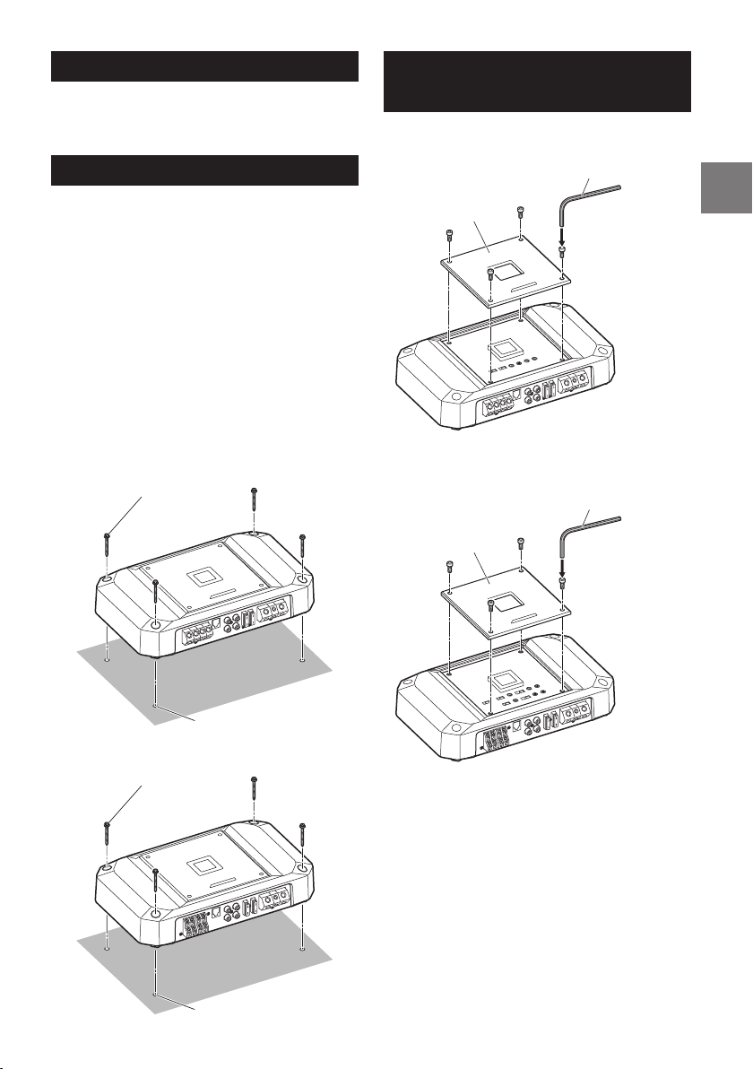
1. Using the amplifier as a template, mark the four
screw locations.
2. Make sure there are no objects behind the
surface that may become damaged during
drilling.
3. Drill the screw holes.
4. Position the R2-A75M/R2-A60F over the screw
holes, and secure with four self-tapping screws.
Self-Tapping Screws (× 4)
(included)
REMOVING THE TOP
COVER
To use the top inner panel, remove the top cover.
Hexagon wrench
(included)
Top cover
R2-A75M
Hexagon wrench
(included)
Top cover
Holes (× 4)
Self-Tapping Screws (× 4)
(included)
Holes (× 4)
R2-A75M
R2-A60F
R2-A60F
3-EN
Page 6
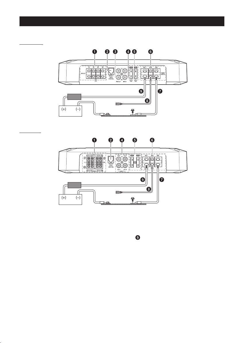
CONNECTIONS
Before making connections, be sure to turn the power off to all audio components.
R2-A75M
1
*
3, 4
*
1
*
R2-A60F
External Fuse*
External Fuse*
2
Vehicle’s chassisVehicle’s battery
2
3, 4
*
Vehicle’s chassisVehicle’s battery
*1 For details on the wires size to be used, refer to the supplied “Cautions on Power Supply Wires Connection” and
“Cautions on Power Supply Wires” (page 20), and then use the wire of the specified size.
*2 Be sure to add an External Fuse (e.g. Fuse Block, Circuit Breaker) with the battery lead as close as possible to the
battery’s positive (+) terminal. Add an external fuse with the same capacity, or a slightly larger capacity, as the sum total
of the fuse capacities of the amplifier.
For details on the fuse capacity of this machine, see “Battery Lead (
*3 Connect all equipment to the same ground point while keeping wire length as short as possible.
*4 To securely connect the ground lead, use an already installed screw.
)” (page 5).
To prevent external noise from entering the audio system
• Locate the unit and route the leads at least 10 cm (4”) away from the vehicle’s harness.
• Keep the battery power leads as far away from other leads as possible.
• Connect the ground lead securely to a bare metal spot (remove any paint or grease if necessary) of the
vehicle’s chassis.
• If you add an optional noise suppressor, connect it as far away from the unit as possible. Your Alpine
dealer carries various noise suppressors, contact them for further information.
• Your Alpine dealer knows best about noise prevention measures so consult your dealer for further
information.
4-EN
Page 7
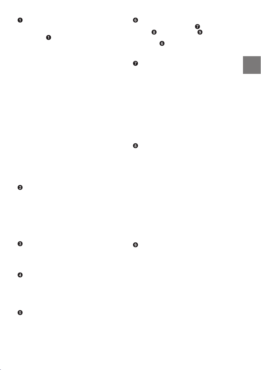
Speaker Output Terminals
Connect the Speaker Output Lead (+) / (–) using
the Hexagon hole screw of the Speaker Output
Terminals ( ).
• For details on how to connect, see “Cautions
on wire lead connections” (page 6).
Be sure to observe correct speaker output
connections and polarity in relation to the other
speakers in the system. Connect the positive
output to the positive speaker terminal and the
negative to negative.
About Subwoofer Input/Output (R2-A75M
only)
• The input is stereo but the output is monaural.
• Reversing subwoofer polarity (swapping
positive and negative connections to the
subwoofer) may be desirable in some
installations for optimum bass performance.
About Bridged Connections (R2-A60F only)
In the bridged mode, connect the left positive to
the positive terminal of the speaker and the
right negative to the negative terminal of the
speaker. Do not use the speaker (–) terminals as
a common lead between the left and right
channels.
NOTE:
• Do not connect the speaker (–) terminal to the
vehicle’s chassis.
Remote Bass Control (optional) (R2-A75M
only)
CH-3/4 Remote Level Control (optional)
(R2-A60F only)
Connect the Remote Bass Control Unit
RUX-KNOB.2 (sold separately) to adjust the
output level remotely. This is not to replace
appropriate gain level setting between the
amplifier and head unit.
Pre-Out Jacks (R2-A75M only)
These jacks provide a line level output. This is an
ideal output for driving a second subwoofer
amp. This output is full-range, and is not affected
by the crossover.
RCA Input Jacks
Connect these jacks to the line out leads on your
head unit using RCA extension cables or
Speaker-RCA Conversion cable (sold separately).
Be sure to observe correct channel connections;
Left to Left and Right to Right.
Fuse
R2-A75M .............................................................40 A × 2
R2-A60F...............................................................30 A × 2
USE THE CORRECT AMPERE RATING WHEN
REPLACING FUSES.
Failure to do so may result in fire or electric
shock.
Power Supply Terminal
Connect the Ground Lead ( ), Remote Turn-on
Lead ( ), and Battery Lead ( ) using the
Hexagon hole screw of the Power Supply
Terminal ( ).
• For details on how to connect, see “Cautions
on wire lead connections” (page 6).
Ground Lead (sold separately)
Connect this lead securely to a clean, bare metal
spot on the vehicle’s chassis. Verify this point to
be a true ground by checking for continuity
between that point and the negative (–)
terminal of the vehicle’s battery. Ground all your
audio components to the same point on the
chassis to prevent ground loops while keeping
wire length as short as possible.
• For details on the wires size to be used, refer to
the supplied “Cautions on Power Supply Wires
Connection” and “Cautions on Power Supply
Wires” (page 20), and then use the wire of
the specified size.
Remote Turn-On Lead (sold separately)
Connect this lead to the remote turn-on
(positive trigger, (+) 12 V only) lead of your head
unit. If a remote turn-on lead is not available, see
“CONNECTION CHECK LIST” section on
page 7 for alternative method.
• When connecting the speaker output leads of
the head unit to this unit with a Speaker-RCA
Conversion cable (sold separately), you do not
need to connect the remote turn-on lead,
owing to the “REMOTE SENSING” function of
this unit. However, the “REMOTE SENSING”
function may not work depending on the
signal source connected. In such a case,
connect the remote turn-on lead to an
incoming power supply cord (accessory
power) in the ACC position.
Battery Lead (sold separately)
Be sure to add an External Fuse (e.g. Fuse Block,
Circuit Breaker) with the battery lead as close as
possible to the battery’s positive (+) terminal.
This fuse will protect your vehicle’s electrical
system in case of a short circuit. See below for
appropriate fuse value requirement:
R2-A75M ....................................................................80 A
R2-A60F...................................................................... 60 A
• For details on the wires size to be used, refer to
the supplied “Cautions on Power Supply Wires
Connection” and “Cautions on Power Supply
Wires” (page 20), and then use the wire of
the specified size.
5-EN
Page 8
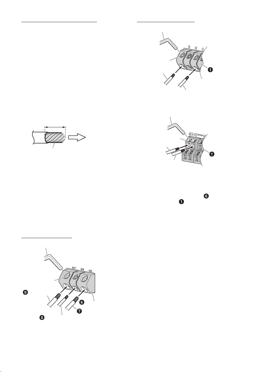
Cautions on wire lead connections
When using third-party wire cables (power supply
wire), use the supplied screws to simplify the
connection. Refer to the description below for the
proper procedure. If you are in doubt about how to
make this connection, consult your dealer.
1. Check the wire size.
• For details on the wires size to be used, refer to
the supplied “Cautions on Power Supply Wires
Connection” and “Cautions on Power Supply
Wires” (page 20), and then use the wire of
the specified size.
• If the wire gauge used is unknown, ask your
dealer.
2. Remove the insulation from the ends of the wire
leads by about 7 – 10 mm (9/32” – 13/32”).
7 – 10 mm
(9/32” – 13/32”)
Speaker Output Terminals
Hexagon Wrench (included)
Hexagon hole
screw
Speaker Output
Lead (+)
Speaker Output Lead (–)
Hexagon Wrench (included)
Speaker Output
Terminals
R2-A75M
Lead end side of
the product
Twist the tip of wire leads
NOTES:
• If length of the exposed wire is too short, a poor
connection may occur causing operation failure
or sound interruption.
• On the other hand, if the length is too long, an
electrical short-circuit may occur.
3. Tighten the hexagon hole screw with the
hexagon wrench (Large or Small) (included) to
secure the lead.
Before making this connection, use insulated
shrink tubing to cover any exposed wire
extending beyond the terminal.
Power Supply Terminal
Hexagon Wrench (included)
Hexagon hole
screw
Battery Lead
Power Supply Terminal
Ground Lead
Remote Turn-On Lead
Hexagon hole
screw
Speaker Output
Lead (+)
Speaker Output Lead (–)
Speaker Output
Terminals
R2-A60F
NOTES:
• Be sure to use the Hexagon hole screw attached
to the Power Supply Terminal ( ) or Speaker
Output Terminals ( ).
• For safety reasons, connect the battery leads last.
• To prevent disconnection of the leads or
dropping of the unit, do not use the cabling to
carry the unit.
6-EN
Page 9
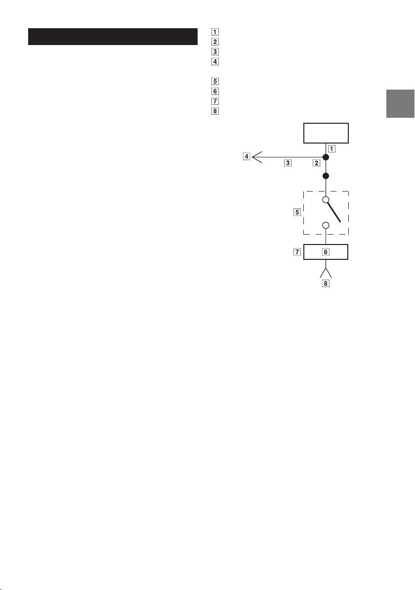
CONNECTION CHECK LIST
Please check your head unit for the conditions
listed below:
Remote Turn-On Lead
a. The head unit does not have a remote turn-on
or power antenna lead.
b. The head unit’s power antenna lead is activated
only when the radio is on (turns off in the tape
or CD Mode).
c. The head unit’s power antenna lead is logic level
output (+) 5 V, negative trigger (grounding
type), or cannot sustain (+) 12 V when
connected to other equipment in addition to
the vehicle’s power antenna.
If any of the above conditions exist, the remote
turn-on lead of your R2-A75M/R2-A60F must be
connected to a switched power source (ignition)
in the vehicle. Be sure to use a 3 A fuse as close
as possible to this ignition tap. Using this
connection method, the R2-A75M/R2-A60F will
turn on and stay on as long as the ignition
switch is on.
If this is objectionable, a SPST (Single Pole,
Single Throw) switch, in addition to the 3 A fuse
mentioned above, may be installed in-line on
the R2-A75M/R2-A60F turn-on lead. This switch
will then be used to turn on (and off) the
R2-A75M/R2-A60F. Therefore, the switch should
be mounted so that is accessible by the driver.
Make sure the switch is turned off when the
vehicle is not running. Otherwise, the amplifier
will remain on and drain the battery.
Blue/White
Power Antenna
Remote Turn-On Lead
To other Alpine component’s Remote Turn-On
Leads
SPST Switch (optional)
Fuse (3 A)
As close as possible to the vehicle’s ignition tap
Ignition Source
Amplifier
7-EN
Page 10
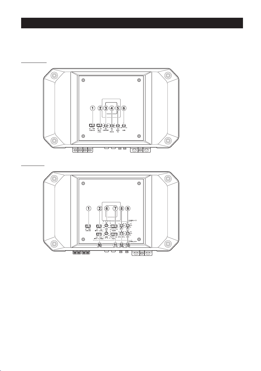
SWITCH SETTINGS
• Before switching each Selector Switch, turn off the power and insert a small screwdriver, etc.,
perpendicularly to the Switch.
• To use the top inner panel, remove the top cover. See “REMOVING THE TOP COVER” (page 3).
R2-A75M
(Top inner panel)
R2-A60F
8-EN
(Top inner panel)
Page 11
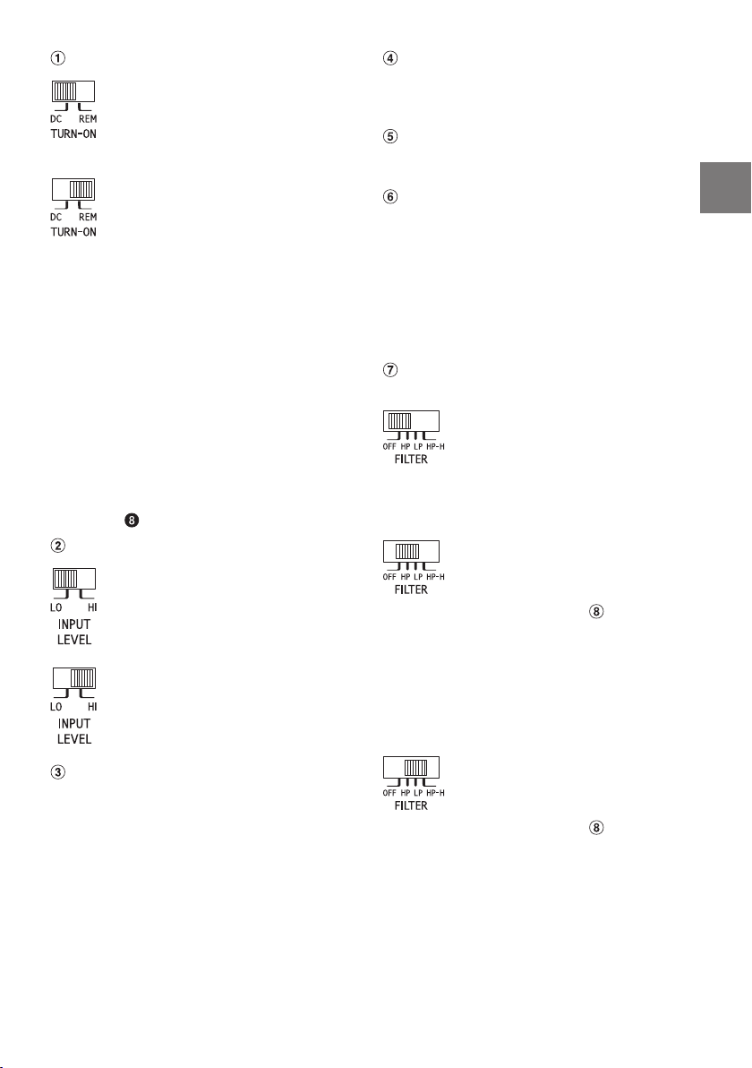
Auto Turn-on Switch
a) For the “DC” Input setting,
connecting the Remote Turn-On
Lead is not required due to the
“REMOTE SENSING” function of
this product.
b) However, the “REMOTE SENSING”
function may not work correctly
depending on the signal source
connected. In such a case,
connect the Remote Turn-On
Lead to an incoming power
supply cord (accessory power) in
the ACC position and switch to
the “REM” Input setting.
• The DC offset auto turn-on circuit was
designed to work with ONLY high level signals
(i.e., speaker level signals). These high level
signals usually come from the amplified
output of radios, head units, and amplifiers.
Because LO signal input (i.e., low level signals)
cannot turn on the amplifier, the REMOTE
trigger signal must be supplied and the REM
setting needs to be used for LO signal input.*
∗ For details on turning on the unit with the
ACC trigger signal, see the Remote Turn-On
) section (page 5).
Lead (
Input Level Switch
a) If input is via the head unit
pre-out line using an RCA
extension cable (sold separately),
set to “LO”.
b) If input is via the head unit
speaker line using a speaker-RCA
conversion cable (sold
separately), set to “HI”.
Crossover Frequency Adjustment Knob
(LP FILTER) (R2-A75M only)
Use this control to adjust the crossover
frequency between 50 Hz to 400 Hz.
Bass EQ Adjustment Knob (R2-A75M only)
Add a 50 Hz bass boost up to +12 dB to tune
your bass response.
Input Gain Adjustment Knob
Set the R2-A75M/R2-A60F input gain to the
minimum position. Using a dynamic CD as a
source, increase the head unit volume until the
output distorts. Then, reduce the volume 1 step
(or until the output is no longer distorted). Now,
increase the amplifier gain until the sound from
the speakers becomes distorted. Reduce the
gain slightly so the sound is no longer distorted
to achieve the optimum gain setting.
Filter Mode Selector Switch
(CHANNEL-1/2) (R2-A60F only)
a) Set to the “OFF” position when the
amplifier will be used for driving
full range speakers or when using
an external electronic crossover.
The full frequency bandwidth will
be output to the speakers with no
high or low frequency attenuation.
b) Set to the “HP” position when the
amplifier is used to drive a tweeter/
midrange system.
At this setting, Crossover Frequency
Adjustment Knob ( ) provides
adjustment between 50 Hz to 400
Hz. The frequencies below the
crossover point will be attenuated
at 12 dB/octave.
NOTE:
• In this case the maximum Bass EQ
boost level is reduced.
Subsonic Filter Adjustment Knob (R2-A75M
only)
The subsonic filter is for cutting ultra low
frequencies from the input signal before being
amplified. Frequencies lower than the specified
frequency are attenuated at 24 dB/octave.
This is desirable for several reasons:
– To protect speakers too small or not capable
of reproducing ultra low frequencies.
– To minimize power wasted from reproducing
inaudible sound.
– To protect subwoofers in vented enclosures
from over excursion below the tuning
frequency.
c) Set to the “LP” position when the
amplifier is used to drive a
subwoofer.
At this setting, Crossover Frequency
Adjustment Knob ( ) provides
adjustment between 50 Hz to 400
Hz. The frequencies above the
crossover point will be attenuated
at 12 dB/octave.
9-EN
Page 12
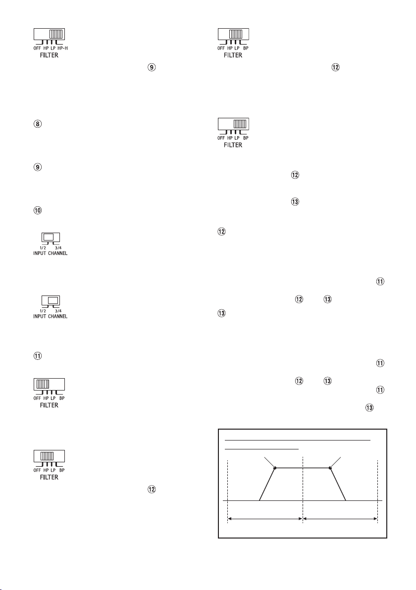
d) Set to the “HP-H” position when the
amplifier is used to drive a tweeter
system.
At this setting, Crossover Frequency
Adjustment Knob ( ) provides
adjustment between 400 Hz to 6
kHz. The frequencies below the
crossover point will be attenuated
at 12 dB/octave.
c) Set to the “LP” position when the
amplifier is used to drive a
subwoofer.
At this setting, Crossover Frequency
Adjustment Knob ( ) provides
adjustment between 50 Hz to 400
Hz. The frequencies above the
crossover point will be attenuated
at 12 dB/octave.
Crossover Frequency Adjustment Knob (HP/
LP FREQ.) (R2-A60F only)
Use this control to adjust the crossover
frequency between 50 Hz to 400 Hz.
Crossover Frequency Adjustment Knob (HP-H
FREQ.) (R2-A60F only)
Use this control to adjust the crossover
frequency between 400 Hz to 6 kHz.
Input Channel Selector Switch (CHANNEL-3/4)
(R2-A60F only)
a) This switch setting is for selecting
either 2-channel or 4-channel input
mode. When set to “1/2”, signal will
be copied from CH-1/2 and sent to
CH-3/4, eliminating the need for
Y-adapters.
b) Setting this switch to “3/4” will keep
both inputs, CH-1/2 and CH-3/4
independent.
A 4-channel source is required for
this mode.
Filter Mode Selector Switch
(CHANNEL-3/4) (R2-A60F only)
a) Set to the “OFF” position when the
amplifier will be used for driving
full range speakers or when using
an external electronic crossover.
The full frequency bandwidth will
be output to the speakers with no
high or low frequency attenuation.
b) Set to the “HP” position when the
amplifier is used to drive a tweeter/
midrange system.
At this setting, Crossover Frequency
Adjustment Knob ( ) provides
adjustment between 50 Hz to 400
Hz. The frequencies below the
crossover point will be attenuated
at 12 dB/octave.
d) Set to “BP” if the amplifier is used to
drive a midbass or midrange
speaker.
Frequencies lower than the
specified frequency set by
Crossover Frequency Adjustment
Knob ( ), and higher than the
frequency specified set by
Crossover Frequency Adjustment
Knob ( ), are attenuated at 12 dB/
octave.
Crossover Frequency Adjustment Knob (HP/
LP/BP-L FREQ.) (R2-A60F only)
Use this control to adjust the crossover
frequency between 50 Hz to 400 Hz.
NOTE:
• When the Crossover Mode Selector Switch (
is set to [BP], adjust the Crossover Frequency
Adjustment Knob ( ) and ( ).
Crossover Frequency Adjustment Knob (BP-H
FREQ.) (R2-A60F only)
Use this control to adjust the crossover
frequency between 400 Hz to 6 kHz.
NOTES:
• When the Crossover Mode Selector Switch (
is set to [BP], adjust the Crossover Frequency
Adjustment Knob ( ) and ( ).
• When the Crossover Mode Selector Switch ( )
is set to [HP] or [LP], adjustment of the
Crossover Frequency Adjustment Knob ( ) is
disabled.
Adjustment range on the Bandpass Filter
Crossover Frequency
[BP-L] [BP-H]
[BP-L] Adjustment range [BP-H] Adjustment range
50 Hz 400 Hz 6 kHz
)
)
10-EN
Page 13
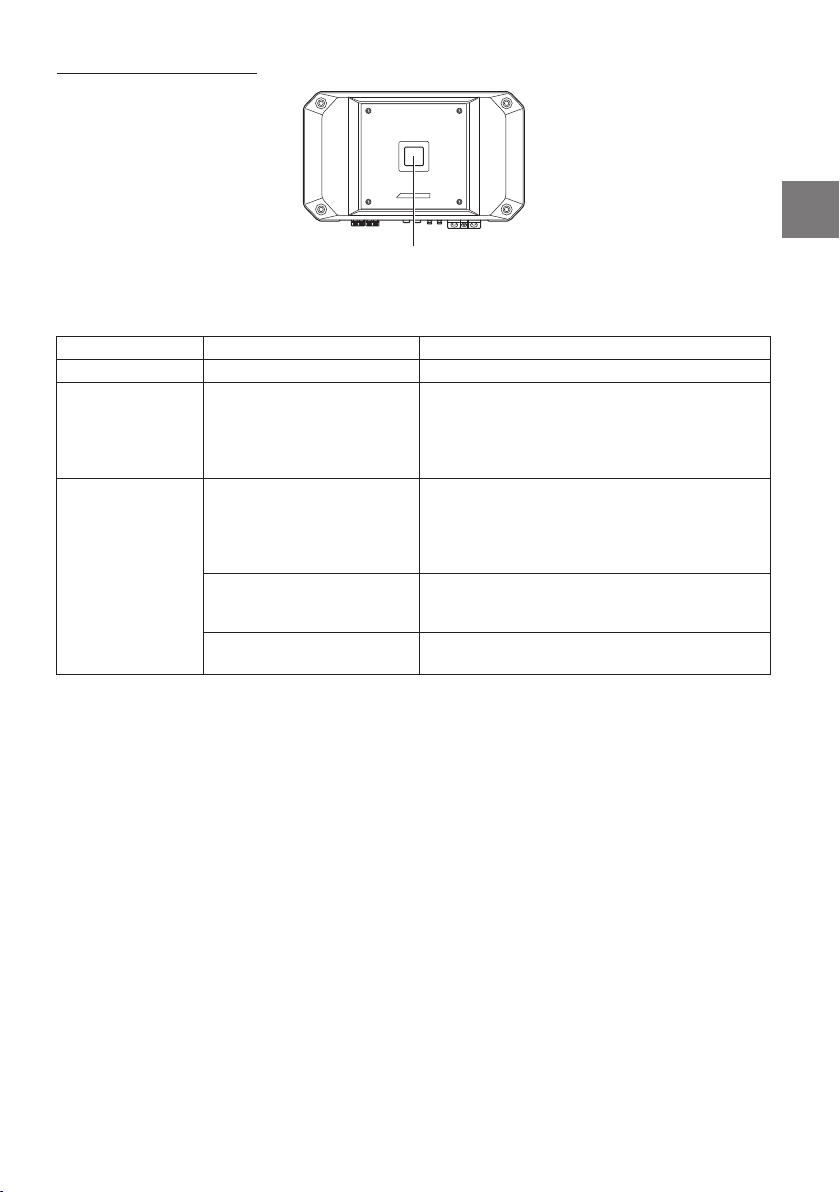
About Power Indicator
Power Indicator
Lights up when power is on.
Is off when power is off.
Indication color Status Solution
Blue Amplifier circuit is normal.
Red
(blinking)
Red Amplifier circuit is abnormal.
Operating temperature is
high.
An electrical short has
occurred, or supply current is
too high.
Operating temperature is too
high.
Power supply voltage is too
high.
Turn down the volume of the head unit (input
signal).
Decrease the vehicle’s interior temperature to a
normal level.
The indicator color changes to blue.
Turn off the power supply and eliminate the cause.
Then turn on the unit and verify that the indicator
color has changed to blue.
If it remains red, turn off the unit and consult your
dealer.
Decrease the vehicle’s interior temperature to a
normal level.
The indicator color changes to blue.
Use the correct power supply voltage.
The indicator color changes to blue.
11-EN
Page 14
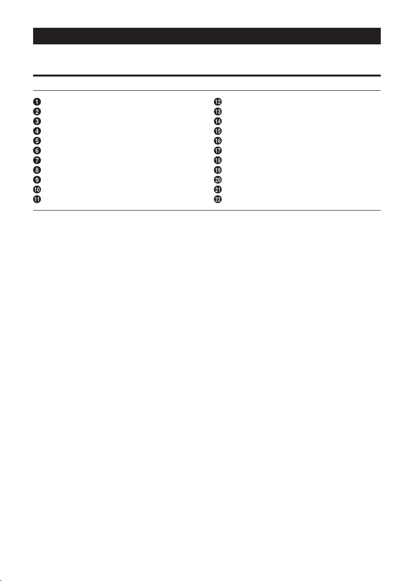
SYSTEM DIAGRAMS
Before making a connection, check the total number of impedance of the speaker connected to the unit. If
you have any questions, contact the nearest Alpine dealer.
Basic Connection Diagram for R2-A75M
Speaker Output Terminals
Remote Bass Control (optional)
Pre-Out Jacks
RCA Input Jacks
Fuse
Power Supply Terminal
Ground Lead (sold separately)
Remote Turn-On Lead (sold separately)
Battery Lead (sold separately)
Head Unit, etc.
Front Output
Rear Output
Subwoofer Output
Front Speakers
Rear Speaker
Subwoofer
Dual Voice Coil Subwoofer
RCA Extension Cable (sold separately)
Speaker-RCA Conversion Cable (sold separately)
Y-Adapter (sold separately)
Front Speakers (Tweeter)
Front Speakers (Midrange)
12-EN
Page 15
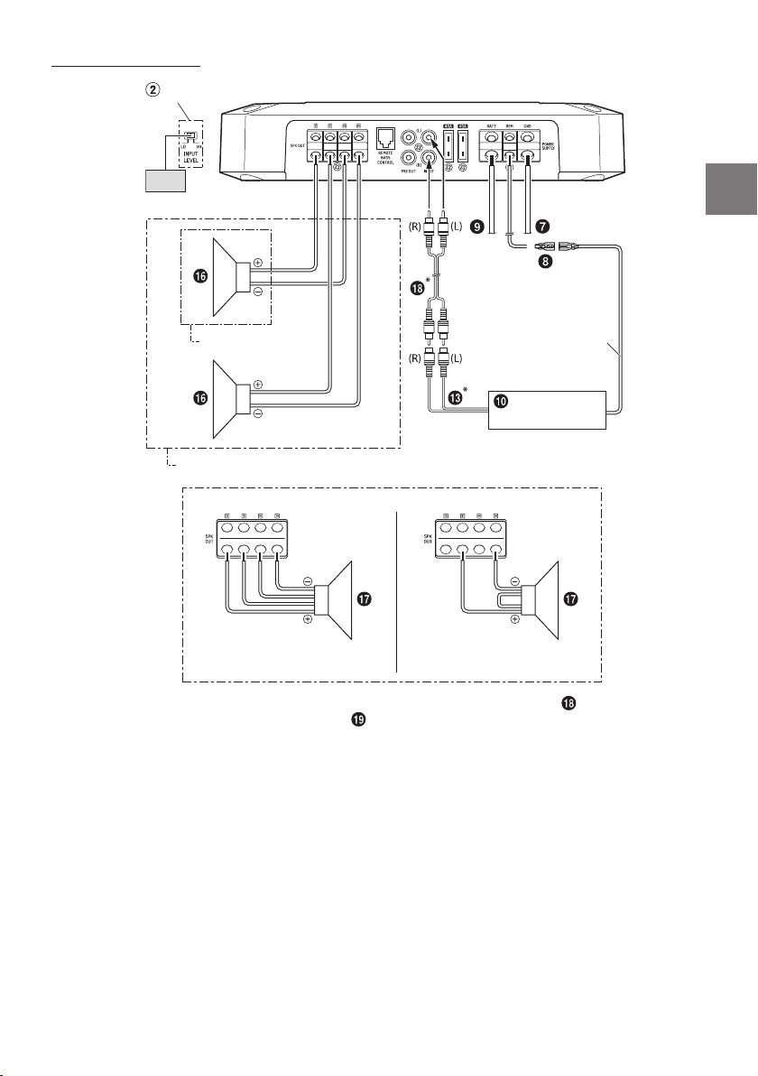
Subwoofer System
Input Level Switch
[LO]
(Top inner panel)
1 Subwoofer System
2 Subwoofer System (MONO)
Remote Turn-On Lead
Head Unit, etc.
Dual Voice Coil Subwoofer System
Parallel connection
Series connection
* If the connected head unit does not have an RCA Output and RCA Extension Cable ( ) cannot be used,
you can use the Speaker-RCA Conversion Cable ( ) (sold separately). For details on how to make a
connection, see “About Connecting to the Speaker Input Level System” (page 19).
• For the 2 Subwoofer System/Dual Voice Coil Subwoofer System, make sure that the minimum impedance
exceeds 2 Ω in total. In addition, the Power Output listed in the SPECIFICATIONS (page 21) is the
specification with the total impedance value.
13-EN
Page 16
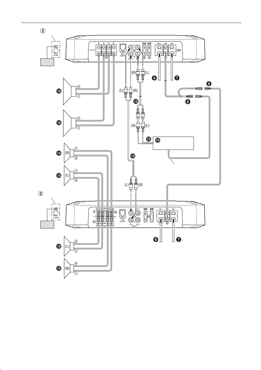
4 Speaker + Subwoofer / 2 Amplifier System (Connection example with R2-A60F)
Input Level Switch
[LO]
(Top inner panel)
Input Level Switch
[LO]
(Top inner panel)
R2-A75M
Head Unit, etc.
Remote Turn-On Lead
R2-A60F
• For details on the connection of R2-A60F, see “Basic Connection Diagram for R2-A60F” (page 15).
14-EN
Page 17
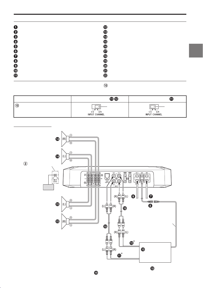
Basic Connection Diagram for R2-A60F
Speaker Output Terminals
Remote Bass Control (optional)
Pre-Out Jacks
RCA Input Jacks
Fuse
Power Supply Terminal
Ground Lead (sold separately)
Remote Turn-On Lead (sold separately)
Battery Lead (sold separately)
Head Unit, etc.
Front Output
For R2-A60F, change the Input Channel Selector Switch ( ) setting according to the number of channels of
the speaker input.
4-Channel Input: 2-Channel Input:
Input Channel Selector Switch
(CHANNEL-3/4)
Rear Output
Subwoofer Output
Front Speakers
Rear Speaker
Subwoofer
Dual Voice Coil Subwoofer
RCA Extension Cable (sold separately)
Speaker-RCA Conversion Cable (sold separately)
Y-Adapter (sold separately)
Front Speakers (Tweeter)
Front Speakers (Midrange)
3/4
1/2
4 Speaker System
Input Level Switch
[LO]
(Top inner panel)
Remote Turn-On Lead
Head Unit, etc.
* If the connected head unit does not have an RCA Output and RCA Extension Cable ( ) cannot be used,
you can use the Speaker-RCA Conversion Cable ( ) (sold separately). For details on how to make a
connection, see “About Connecting to the Speaker Input Level System” (page 19).
15-EN
Page 18
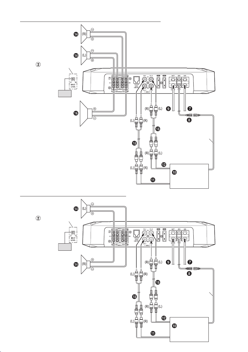
2 Speaker + Subwoofer System (Bridged Connections)
Input Level Switch
[LO]
(Top inner panel)
Remote Turn-On Lead
Head Unit, etc.
2 Speaker System (Bridged Connections)
Input Level Switch
[LO]
(Top inner panel)
16-EN
Remote Turn-On Lead
Head Unit, etc.
Page 19
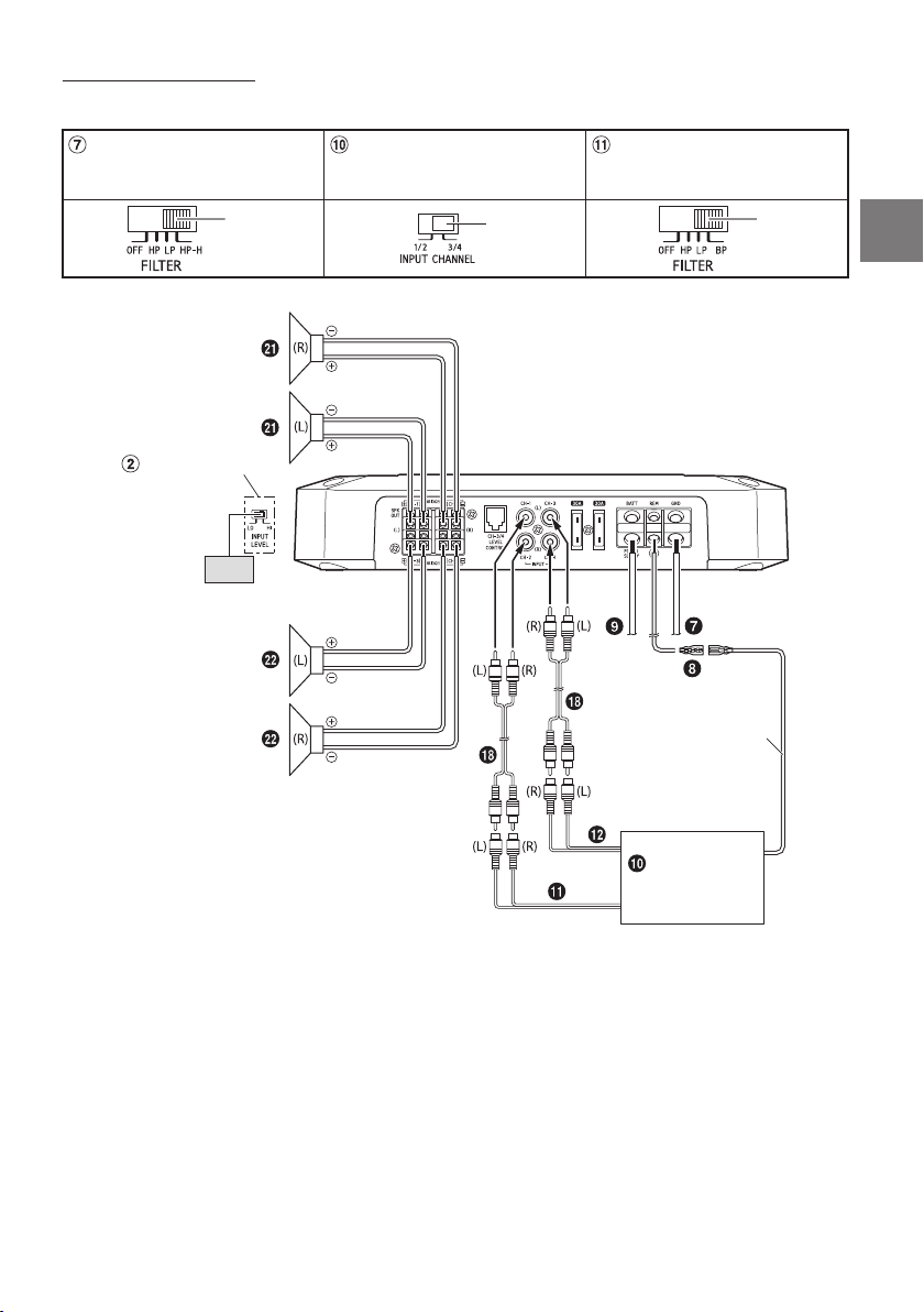
Front 2-Way System
When using the Front 2-Way System, set each switch as follows.
Crossover Mode Selector Switch
(CHANNEL-1/2)
HP-H
Input Level Switch
[LO]
(Top inner panel)
Input Channel Selector Switch
(CHANNEL-3/4)
3/4
Crossover Mode Selector Switch
(CHANNEL-3/4)
BP
Remote Turn-On Lead
Head Unit, etc.
17-EN
Page 20
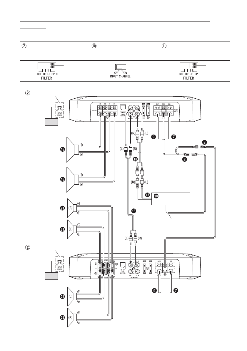
Front 2-Way + Subwoofer / 2 Amplifier System (Connection example with
R2-A75M)
When using the Front 2-Way + Subwoofer / 2 Amplifier System, set each switch as follows.
Crossover Mode Selector Switch
(CHANNEL-1/2)
HP-H
Input Level Switch
[LO]
(Top inner panel)
Input Channel Selector Switch
(CHANNEL-3/4)
1/2
Crossover Mode Selector Switch
(CHANNEL-3/4)
BP
R2-A75M
Head Unit, etc.
Remote Turn-On Lead
Input Level Switch
(Top inner panel)
18-EN
[LO]
R2-A60F
Page 21
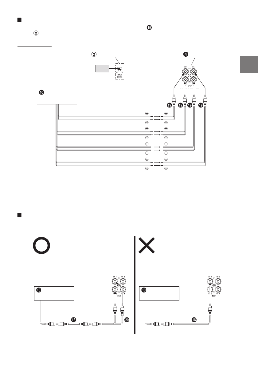
About Connecting to the Speaker Input Level System
When connecting by using the Speaker-RCA Conversion Cable ( ) (sold separately), switch the Input Level
Switch ( ) to “HI”.
e.g. R2-A60F
Input Level Switch
[HI]
Head Unit, etc.
Front Speaker output lead (L)
Front Speaker output lead (R)
Rear Speaker output lead (R)
Rear Speaker output lead (L)
RCA Input Jacks
• Do not mistake the Speaker Output Lead on the head unit side connected to this unit.
Front Speaker output (L)/(R) to CH1/CH2, Rear Speaker output (L)/(R) to CH3/CH4
• For the “Speaker Input Level System” setting, connecting the Remote Turn-On Lead is not required due to
the “REMOTE SENSING” function of this product. However, the “REMOTE SENSING” function may not work
depending on the signal source connected. In such a case, connect the Remote Turn-On Lead to an
incoming power supply cord (accessory power) in the ACC position.
Important Tips on Bridging an Amplifier
Low output will result if only one channel input is used. The Y-adapter is not required if a stereo/mono pair
line output is used to drive both inputs of the bridged amp.
Proper connection
Head Unit, etc. Head Unit, etc.
One signal
Improper connection
One signal
19-EN
Page 22
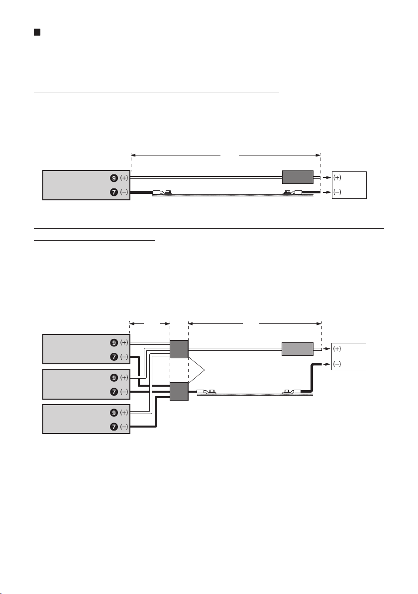
Cautions on Power Supply Wires
Use the specified wire size according to the total fuse capacity of the amplifier to be installed and the wire
length.
For details on the wire size to be used, refer to the supplied “Cautions on Power Supply Wires Connection”
and the following connection example.
Connection example when installing an amplifier alone
• When the wire length from the amplifier to the vehicle’s battery is (A)
Wire size used for (A): 4 AWG/21 mm2 (Max. length 8 m)
• External Fuse capacity: Make it equal to or larger than the fuse capacity of the amplifier
R2-A75M: equal to or larger than 80 A
R2-A60F: equal to or larger than 60 A
(A)
External Fuse
Amplifier
Vehicle’s chassis
Vehicle’s battery
Connection example when installing two amplifiers with a fuse capacity of 80 A
and one amplifier with 60 A
• When the wire length from each amplifier to the distribution block is 1 m
Wire size used for (B): 4 AWG/21 mm
• When the wire length from the distribution block to the vehicle’s battery is 5 m
Wire size used for (C): 1/0 AWG/53 mm2 or 4 AWG/21 mm2 x 2
• External Fuse capacity: Make it equal to or larger than total fuse capacity of the number of amplifiers
installed
80 A + 80 A + 60 A = equal to or larger than 220 A
Amplifier
(e.g. 80 A)
Amplifier
(e.g. 80 A)
Amplifier
(e.g. 60 A)
NOTE:
• If the length of the power and ground cables exceed 1 m, or if you connect more than one amplifier, a
distribution block should be used.
2
(B)
Distribution block
(C)
External Fuse
Vehicle’s battery
Vehicle’s chassis
20-EN
Page 23
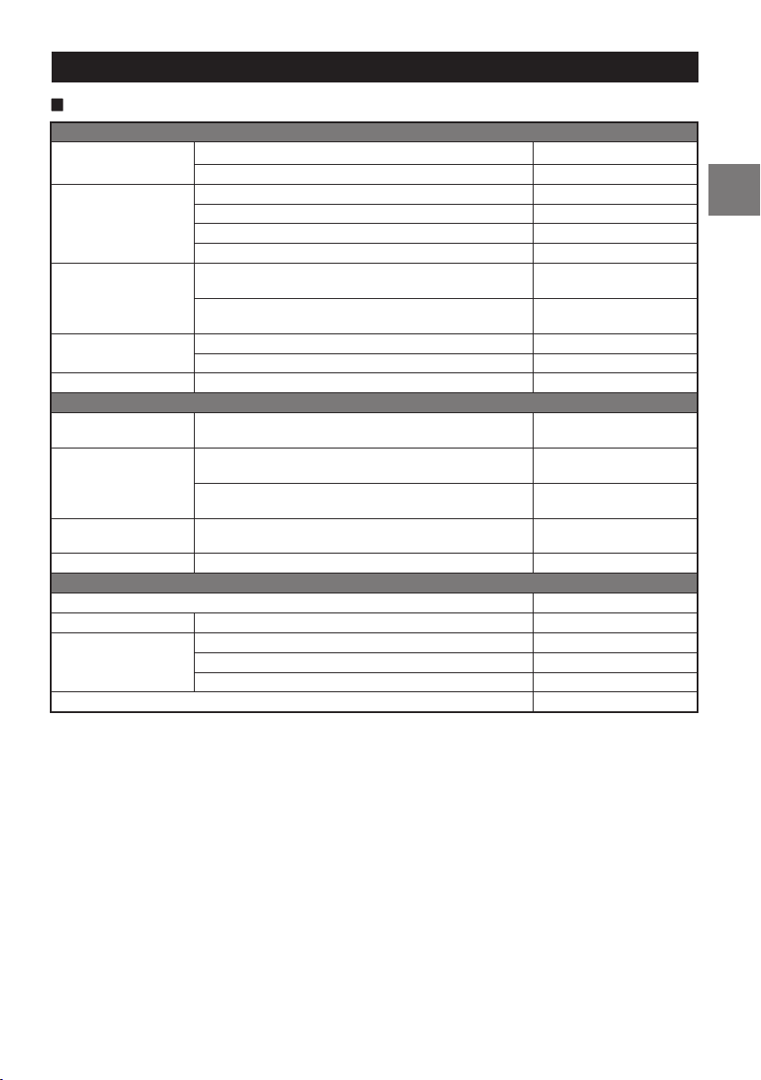
SPECIFICATIONS
R2-A75M
Performance
Power Output
THD+N
S/N Ratio
Frequency Response
Damping Factor Ref.: 10 W into 4 Ω at 100 Hz >250
Control
Input Sensitivity
Crossover
Equalizer Bass EQ (fc=50 Hz)
Remote Level* Linear Attenuation 0 to –20 dB
General
Input Impedance >10 kΩ
Preamp Output CH-1/2 Input Pass-through, Buffered 4 V max
Dimensions
Weight 3.5 kg (7 lb 10 oz)
* Requires optional RUX-KNOB.2.
NOTE:
• Specifications and design are subject to change without notice.
Per Channel, Ref.: 4 Ω, 14.4 V 500 W RMS × 1
Per Channel, Ref.: 2 Ω, 14.4 V 750 W RMS × 1
Ref.: 10 W into 4 Ω ≤0.04%
Ref.: 10 W into 2 Ω ≤0.06%
Ref.: Rated Power into 4 Ω ≤1.0%
Ref.: Rated Power into 2 Ω ≤1.0%
IHF A-wtd + AES-17
Ref.: 1 W into 4 Ω
IHF A-wtd + AES-17
Ref.: Rated Power into 4 Ω
+0/–3 dB, Ref.: 1 W into 4 Ω 10 Hz - 400 Hz
+0/–1 dB, Ref.: 1 W into 4 Ω 15 Hz - 325 Hz
RCA Input
Ref.: Rated Power into 4 Ω
Variable LPF
Variable Subsonic
Width 282 mm (11-1/8”)
Height 55 mm (2-3/16”)
Depth 165 mm (6-1/2”)
>75 dB
>102 dB
Hi: 0.4 - 10 V
Lo: 0.1 - 4.0 V
50 Hz - 400 Hz
(–24 dB/oct.)
8 Hz - 40 Hz
(–24 dB/oct.)
0 to +12 dB
(Variable)
21-EN
Page 24
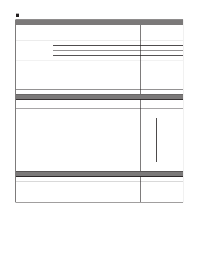
R2-A60F
Performance
Per Channel, Ref.: 4 Ω, 14.4 V 100 W RMS × 4
Power Output
THD+N
S/N Ratio
Frequency Response
Damping Factor Ref.: 10 W into 4 Ω at 100 Hz >100
Control
Input Select
Input Sensitivity
Crossover
Remote Level* Linear Attenuation
General
Input Impedance >10 kΩ
Dimensions
Weight 3.3 kg (7 lb 3 oz)
* Requires optional RUX-KNOB.2.
NOTE:
• Specifications and design are subject to change without notice.
Per Channel, Ref.: 2 Ω, 14.4 V 150 W RMS × 4
Bridged, Ref.: 4 Ω, 14.4 V 300 W RMS × 2
Ref.: 10 W into 4 Ω ≤0.04%
Ref.: 10 W into 2 Ω ≤0.06%
Ref.: Rated Power into 4 Ω ≤0.5%
Ref.: Rated Power into 2 Ω ≤1.0%
IHF A-wtd + AES-17
Ref.: 1 W into 4 Ω
IHF A-wtd + AES-17
Ref.: Rated Power into 4 Ω
+0/–3 dB, Ref.: 1 W into 4 Ω 10 Hz - 45 kHz
+0/–1 dB, Ref.: 1 W into 4 Ω 20 Hz - 20 kHz
Selectable Input Signal
Configuration (2ch/4ch Input)
RCA Input
Ref.: Rated Power into 4 Ω
Variable HPF/LPF/HPF-H CH-1/2
Variable HPF/LPF/BPF CH-3/4
Width 282 mm (11-1/8”)
Height 55 mm (2-3/16”)
Depth 165 mm (6-1/2”)
>80 dB
>100 dB
CH-3/4:
CH-1/2 or CH-3/4
Hi: 0.5 - 10 V
Lo: 0.2 - 4.0 V
HPF/LPF:
50 Hz - 400 Hz
(–12 dB/oct.)
HPF-H:
400 Hz - 6 kHz
HPF/LPF/BPF-L:
50 Hz - 400 Hz
BPF-H:
400 Hz - 6 kHz
(–12 dB/oct.)
CH-3/4:
0 to –20 dB
22-EN
Page 25
To customers/Hinweis an Kunden/A l’attention de l’utilisateur/
Información para los clientes/Informazioni per i clienti/
Till kunder
ENGLISH
Information on Disposal of Old Electrical and Electronic
Equipment and Battery (applicable for countries that
have adopted spearate waste collection systems)
If you want to dispose this product, do not mix it with
general household waste. There is a separate collection
system for used electronic products in accordance with
legislation that requires proper treatment, recovery and
recycling. Contact your local authority for details in
locating a recycle facility nearest to you. Proper recycling
and waste disposal will help conserve resources whist
preventing detrimental effects on our health and the
environment.
DEUTSCH
Informationen zur Entsorgung von Elektro- und
Elektronikgeräten und Batterien (anwendbar für
Länder, die ein separates Sammelsystem übernommen
haben)
Wenn Sie dieses Produkt entsorgen wollen, entsorgen Sie
dies nicht über den normalen Hausmüll. Es gibt ein
separates Sammelsystem für gebrauchte elektronische
Geräte in Einklang mit den Rechtsvorschriften, die eine
angemessene Behandlung, Verwertung und Recycling
erfordert. Kontaktieren Sie Ihre lokale Behörde für Details
bei der Suche nach einer Recycling-Anlage Ihrer Nähe.
Ordnungsgemäße Verwertung und Entsorgung trägt dazu
bei, Ressourcen zu schonen und schädliche Auswirkungen
auf unsere Gesundheit und die Umwelt zu verhindern.
FRANÇAIS
Information sur le traitement des Déchets Electriques
et Electroniques (DEEE), pour les pays ayant adoptés
un traitement séparés de ces déchets
Si vous possédez des appareils Electriques ou
Electroniques usagés, ne les jetez pas dans le système
général. Conformément à la Directive Européenne,
transposée dans votre pays, il existe un système séparé de
recyclage et de traitement de ces déchets. Veuillez
contacter l’administration locale afin de prendre
connaissance du lieu de recyclage et de traitement le plus
proche de chez vous. Ce système est destiné à protéger
l’environnement.
ESPAÑOL
Información sobre la eliminación de Viejos Equipos
Eléctricos y Electrónicos, así como Baterías (aplicable
en los países que han adoptado sistemas de recogida
selectiva de residuos)
Si desea deshacerse de este producto, no lo mezcle con los
residuos generales de su hogar. Existe un sistema de
recogida selectiva para aparatos electrónicos usados de
acuerdo a la legislación, que requiere un tratamiento
adecuado de recuperación y reciclado. Póngase en
contacto con las autoridades locales para obtener más
información sobre el punto de recogida y tratamiento más
cercano. El apropiado reciclado y eliminación de residuos
ayuda a conservar los recursos y a contribuir en la
prevención de los efectos negativos y perjudiciales sobre
nuestra salud y el medio ambiente.
ITALIANO
Avvertenze sullo smaltimento di dispositivi elettronici
guasti o usati e delle batterie (valido per quei paesi che
hanno adottato il sistema di raccolta differenziata)
In caso di smaltimento del prodotto, non gettarlo
assolutamente insieme ai rifiuti domestici. Esiste un
sistema di raccolta differenziata per prodotti elettronici
conforme alle leggi che regolano il trattamento, il deposito
e il riciclo. Contattare le autorità locali per ulteriori
informazioni e per trovare il punto di raccolta più vicino
alla vostra abitazione. Un corretto riciclo e un appropriato
smaltimento dei rifiuti contribuirà a conservare le risorse e
a prevenire effetti nocivi sia sulla salute che sull’ambiente.
SVENSKA
Information om återvinning av avfall från elektriska
och elektroniska produkter och batterier (tillämpligt
för länder som har infört system för återvinning och
sortering av avfall)
Om du vill slänga denna produkt, blanda den ej med
vanliga hushållssopor. Det finns ett separat direktiv för
elektronikåtervinning som kräver rätt hantering av
förbrukade produkter. Kontakta din kommun angående
information om var du kan lämna den för återvinning. Rätt
återvinning och sophantering sparar jordens resurser och
vår hälsa samt miljö.
Page 26
ALPS ALPINE NORTH AMERICA, INC.
1500 Atlantic Blvd,
33/4 Rama 9 road, Huay Kwang, Bangkok, 10310, Thailand
電話:03-5499-4531
Auburn Hills, Michigan 48326, U.S.A.
Phone 1-800-ALPINE-1 (1-800-257-4631)
Ohmstrasse 4, 85716 Unterschleissheim, Germany
ALPS ALPINE EUROPE GmbH
Phone: +49 (0) 89-32 42 640
For contact information on your respective country,
please visit www.alpine-europe.com.
ALPS ALPINE EUROPE GmbH
Aurora House, Deltic Avenue, Rooksley, Milton Keynes,
MK13 8LW, United Kingdom
ALPINE ELECTRONICS OF AUSTRALIA PTY., LTD.
Hallam Victoria 3803, Australia
ALPS ALPINE ASIA CO., LTD.
The 9th Towers, Tower B, 24th Floor, Unit TNB01-03,
アルパインマーケティング株式会社
〒145-0067 東京都大田区雪谷大塚町1番7号
Phone: 0345-313-1640
161-165 Princes Highway,
Phone 03-8787-1200
Phone +66 (2) 090 9596
Shenzhen Ketu Verpackungsprodukte Co., Ltd.
Building 2, Nan’an Industrial Zone, Hongxing community, Songgang street, Shenzhen, China 68-44781Z33-B (Y-A5)
 Loading...