

Page 1

Owner’s Manual
EN
DE
FR
PXE-C80-88
8 CHANNEL AUDIO PROCESSOR AMPLIFIER
ES
RU
Page 2

Page 3

ENGLISH
Contents
Instructions
Warning ..................................................................3
Points fo r Safe Use ... ................... ................ ..... 3
About the software license of the product ..........5
Preparation work...................................................6
Accessory List ... ................... ................... ........... 6
Connectio ns and Functions ................ ......... 7
Connectio ns and Functions ................ ......... 8
Pairing The Device.................................................9
Using the mobile app ............................................9
Using the PC application.......................................9
Computer Software ............................................ 10
Precautio ns installation .. ................... ................. 10
Computer Software Introduction ............10
Connecti on ........... ............... ............ ............... ......... 11
Connectio n Settings . ..................... ............... 11
File Setti ngs ...... ................... ................... ................. 11
Option Sett ing .............. ..................... ..................... 11
Firmware Update Settin gs .............. ........... 11
Restore F actory Settings ... ................... .......12
Shutdown d elay setting ..................... .........12
Language S ettings ................... ..................... 12
View Abo ut ................ ................... ................... 12
Encryptio n Settings . ..................... ..................... ...12
Master vol ume setting .............. ..................... .....13
Function Page Selection . ..................... ............... 13
Home Page ..................... ..................... ............. 14
Main Sour ce Selection .............. ............. 14
Main Source Attenuation Setting. .....14
Mix Source Selection...... ..................... ...14
Channel Se ttings. ..................... ............... 14
X-Over Settings........................................15
EQ .......... ............. ............... .............. ............. .......15
Customize the output channel
type ............ ................... ..................... ...15
Channel Mu te Setting.. ..................... .....16
EQ Adjust ment ................. ................... .....16
Equalizer S ettings...... ..................... .........16
Sync Setti ngs......... ................... ................. 17
Channel settings......................................17
X-Over sett ings......... ..................... ...........17
Preset soun d settings....... ..................... .17
TCR ........ ............. ............... ............ ............... .......17
Mix ....... ............. ............... ............ ............... .........1 8
Input mo de selection ... ................... .............18
Output mod e selection ...... ..................... .....18
Anti EQ .............. ....................... ..................... .....18
H.level inpu t channel type ............ .......19
Fixed the RT A data.. ..................... ...........19
EQ Adjust ment ................. ................... .....19
Equalizer se ttings ................... .................1 9
Signal gain .. ..................... ..................... .....19
Sensitivi ty.... ................... ................... .........19
AutoEQ .... ....................... ....................... .............19
Volume Adju stment ................ ...............19
Measureme nt.......... ..................... .............20
Tuning .... ................... ..................... .............21
Managing A mps........... ....................... .....23
Mobile Phone App ...............................................24
Overview .................... ..................... ..................... .....24
Setup ....... ............ ............... ............ ............... .....24
Connect .. .............. ............... ............. .............. ...24
Volume Ad justment .................. ................... .25
Measurem ent ....... ............... ............. .............. .25
Tuning ..... .............. ............. ............... ............ .....25
Managing Amps and Re connecting ...... .26
1-EN
Page 4

Wired Controller ................................................. 27
Startup Scr een . ..................... ..................... .....27
Master Volu me ................... ..................... .......27
Subwoofer Volume (SUB W) ......................27
Sound Effect Presets (PRESET) ..................27
Main Sourc e ........... ..................... ..................... 28
Main Sourc e Attenuation .. ..................... .....28
Mix Sourc e ........... ................... ................... .......28
Channel Se ttings ............ ..................... ...........2 9
Specifications...................................................... 31
Function Parameter............................................ 32
Open Source License .......................................... 33
2-EN
Page 5
Instructions
Warning
Points for Safe Use
• Please read this manual carefully before using the
machine and system components. This manual
contains instructions on h ow to use this product
safely and effect ively. If failure to follow the
instructions in this manual causes malfunctions,
Alpine will not assume any responsibility.
• This manual uses various icons to explai n how to
use this product safely, and reminds you to pay
attention to the dangers that may be caused by
improper connection and operation. The
meaning of these icons will be explained below. A
complete understanding of the meaning of these
icons is very important for the correct use of this
manual and this system.
Warn ing
• It is very dangerous to operate this system
while driving. The user should stop before
operating the software.
• Road conditions and l aws take precedence
over the information displayed on the map:
When driving, you should abide by actual
traffic restrictions and conditions.
• This software is specially designed for this
machine and cannot be used in combination
with other hardware.
Warn ing
This symbol indicates important
instructions. Failure to heed these
instructions can result in serious injury or
even death.
Do not use any features that will distract you
while driving
Any function that affects your concentration should
only be used aft er the car has come to a complete
stop. To use these functions, please park your
vehicle in a safe place first. Otherwise, an accident
may result.
Do not disassemble or m odify
Otherwise, it may cause an accident, fire or electric
shock.
The volume must be maintained at a level where
the noise outside the car ca n be heard while
driving
Inaudible emergency vehicle sirens and road
warning signals (train intersections, etc.) are very
dangerous and may cause accidents. In addition,
excessive volume may cause hearing loss.
This product is only suitable for cars with 12V
negative grounding
Otherwise, it may cause a fire and other accidents.
Small objects such as bolts or screws should be
kept out of the reach of childre n
Swallowing small objects may cause serious injury.
Once swallowed by mistake, please immediately
medical.
When replacing the fuse, you must choose a fu se
with the correc t ampere value
Otherwise, it may cause a fire or electric shock.
Do not block the ventilation holes or heat sink
Otherwise, it may cause internal heat build-up and
may cause a fire.
This product ca n only be used in 12V m obile
applications
If used in non-designed applications, it may cause
fire, electric shock or other injuries.
Make the correct connection
If it is not connected properly, it may cause fire or
product damage.
Before wiring, disconnect the cable from the
negative terminal of the battery
Otherwise, it may cause electric shock or injury due
to electrical short circuit.
3-EN
Page 6

Do not let the cable be entangled with
surrounding objects
Arrange the wires and cables in accordance with the
requirements of the manual to prevent them from
becomin g obstructiv e while drivin g. Cables or wi res
that obstruct or hang on the steering wheel, shift
lever, brake pedal, etc. are extremely dangerous.
Do not splice ca bles
Do not cut the cable insulation to supply power to
other equipment. Otherwise, the current carrying
capacity of the wire will be exceeded, resulting in
fire or electric shock.
Do not damag e the pipe or wiring when drilling
When drilling holes in the chassis for installation, be
careful not to touch, damage or obstruct the pipes,
fuel lines, fuel tanks or wires. If you don't pay
attention, it can cause fire.
Do not use bolts or nuts in b rakes or steering
systems for grounding connections
Never use bolts or nuts used in brakes or steering
systems (or any other safety-related systems) or fuel
tanks for installation or grounding connections. The
use of such parts will cause the car controller to fail,
resulting in fire and so on.
Do not install on the steering wheel o r gear lever,
etc., which may hinder the operation of the car
Otherwise, it will obstruct the front line of sight or
obstruct moving parts, etc., causing serious
accidents.
Do not to uch the prod uct while w orking
The temperature of the product is high when
working,and it may be scalded when touched.
Notice
This symbol indicates important
instructions. Failure to heed these
instructions may result in injury or major
property damage.
When there is a problem, please stop using it
immediate ly
Otherwise, it may cause personal injury or damage
to the product. Please return this product to an
authorized Alpine dealer or the nearest Alpine
service center for repair.
Ask professionals for wiring and installation
The wiring and installation of this product require
professional skills and experience. For safety
reasons, please contact the dealer where you
purchased the product for installation.
Use designated accessories and install securely
Make sure to use only designated accessories. The
use of non-designated parts may cause internal
damage to the device, or it may not be securely
installed in place. This can cause parts to loosen and
cause danger or product failure.
Recommended Screw fixing torque between
attachments BKT an d product: 37±5 N/cm
Screw hole may be damaged if using large torque.
Arrange the wires to avoid crimping or bei ng
squeezed by sharp metal edges
The arrangement of wires and cables should be far
away from moving parts (such as seat tracks) or
sharp edges or corners. This will avoid crimping and
damage to the wires. If the wiring passes through a
metal hole, a rubber gasket should be used to
prevent the wire insulation from being cut by the
edge of the metal hole.
Do not install in high humidity or dusty locations
Avoid installing the device in a location with high
humidity or dust. Moisture or dust invades the
device and can cause product failure.
4-EN
Page 7

Precautions
Product cle aning
Please use a dry soft cloth to clean the product
regularly. If the dirt is difficult to remove, soak a soft
cloth with water onl y. Any other solvent m ay
dissolve.
temperat ure
Before turning on the machine, please make sure
that the temperature in the car is between +60°C
and -20°C.
Maintain
If you encounter a problem, do not repair it yourself.
Please return this product to an authorized Alpine
dealer or the nearest Alpine service center for repair.
Installation location
This machine cannot be installed in any of the
following place s:
• Near direct sunlight and heat sources
• Places with high humidity and near water sources
•Dusty places
• Locations subject to severe vibration
About the software license of the product
The software installed in the product contains open-source software. See the following Alpine website for details
on the open source software.
[CN] https://www.alpine.com.cn/c/aftermarket_ oss/download/CSP_Series
[EN] https://www.alpine.com.cn/e/aftermarket_oss/download/CSP_Series
* Appropriate recycling channels should be adopted for the disposal of electronic products to reduce electronic
waste pollution.
5-EN
Page 8
Preparation work
Accessory List
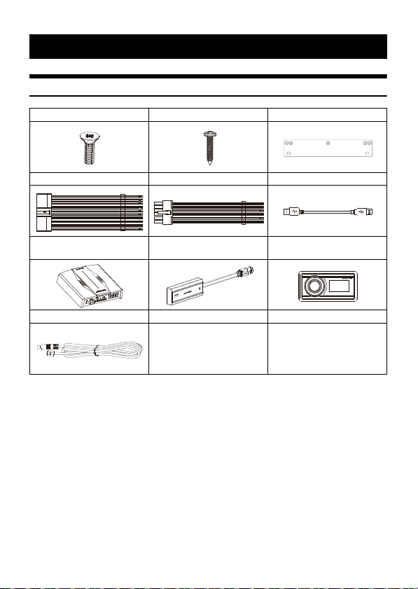
Machine Screw × 10 Self-tapping Screw × 4 Mounting Brackets × 2
20P Input Cable 12P Output Cable USB Cable
6-EN
Main Unit
Controller cable
External Bluetooth Module
(KCE-800BT)
Wired controller
(RUX-CSP1)
Page 9
Connections and Functions
'
0
2
%
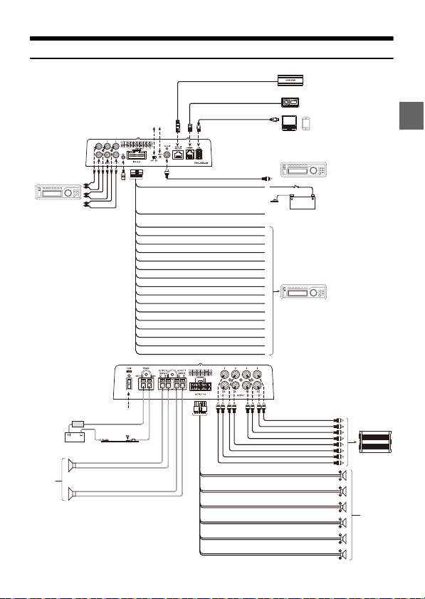
External Bluetooth
Car audio player
(Sold separately)
ACC (Red) Ignition key
Battery
To External Power Amplifier etc.
REMO (Yellow/Red)
Car audio player (Sold separately)
High Level IN1+ (White)
High Level IN1- (White/Black)
High Level IN2+ (Blue)
High Level IN2- (Blue/White)
High Level IN3+ (Yellow)
High Level IN3- (Yellow/White)
High Level IN4+ (Purple)
High Level I N4- (Purple/ White)
High Level IN5+ (Gray)
External Fuse
External Power
Amplifier (Sold
separately)
Speakers
PC Mobile player
Car audio player (Sold separa tely)
Controller
High Level IN5- (Gray/White)
High Level IN6+ (Pink)
High Level IN6- (Pink/White)
High Level IN7+ (Orange)
High Level I N7- (Orange/ White)
High Level IN8+ (Green)
High Level IN8- (Green/White)
Vehicle’s battery
Vehicle’s chassis
Speakers
Subwoofer
Speaker OUT 1 + (White)
Speaker OUT 1 - (White/Black )
Speaker OUT 2+ (Blue)
Speaker OUT 2 - (Blue/White)
Speaker OUT 3+ (Yellow)
Speaker OUT 3- (Yellow/White)
Speaker OUT 4 + (Purple)
Speaker OUT 4- (Purple/White)
Speaker OUT 5+ (Gray)
Speaker OUT 5- (Gray/White)
Speaker OUT 6+ (Red)
Speaker OUT 6- (Red/White)
USB cable (included)
7-EN
Page 10

Connections and Functions
RCA Audio Input Jacks
3 groups of RCA audio signal input, which can
be connected to the RCA audio signal output of
car audio player.
Externa l Mic Input Jack
Connect to the ex ternal microphone (Sold
separately) for Auto EQ on your PC.
Switched Power Lead (Ignition)
Connect this lead to an open terminal on the
vehicle’s fuse box or another unused power
source that provides(+)12V only when the
ignition is turned on or in the accessory
position.
Remote Turn-On Lead
Connect this lead to the remote turn-on le ad of
your am plifier etc.
~ High Level Input Leads
Connect to the high-level output of the car
audio player.
Input Select Switch
When the switch is pulled to the “ACC”
terminal, ACC starts the machine; when it is
pulled to the “HOST” terminal, the machine is
started by the high level input signal H1-/H1+.
Power Indicator Light
Coaxial Input Jack
Connect the car audio coaxial cable, switch the
audio source of the machine to the digital
signal input, and play the coaxial digital signal.
To prevent external noise from entering the audio system.
• The installation position of the machine and the wiring arrangement should be at least 10cm away from
the automobile wiring harness.
• Try to keep the battery power cord away from other wires.
• Securely connect the ground wire to the bare metal contacts of the car chassis (remove any paint, dirt or
grease if necessar y).
• If you want to attach an optional noise suppressor, please try to keep it away from the machine when
connecting. Your Alpine dealer has various types of noise suppressors, please contact them for details.
• Your Alpine dealer is proficient in noise prevention methods, please consult your dealer for details.
Externa l Bluetooth Connector
After the connection is successful, the
Bluetooth is always on.
Contro ller Connector
Connect the controller.
USB Connector
It can be connec ted to a computer via a USB
cable for detailed tuning operations and
settings.
And it can be connected with mobile player as
USB audio (DAC).
Car Audio Player ( Sold separately)
Connect the car audio player.
Fus e
Insert one 40A fuse.
Power Supply Terminal
Connect the car battery.
CH7-8 Speaker Output Terminals
The amplifier outputs are connected to the
subwoofers.
CH1-6 Speaker Output Leads
The amplifier outputs are connected to the
speaker.
Pre-Out Jacks
4 groups of RCA audio signal output, which can
be connected to external power amplifiers.
External Power Amplifier (Sold
separately)
Connect external power amplifiers.
8-EN
Page 11

Pairing The Device
1 Open the setti ngs menu of the smart device.
2 Go to t he Bluetooth settings a nd make sure it is turne d on.
3 Scan for devices.
4 The tablet or phone will find DSP-HD-XXXXXX.Click to connect to it.
Note:
• The light on the Bluetooth adapter will flash until a device has been paired. Once a device is paired it will
remain steady.
• Only one Blue tooth-compatible dev ice can be paired, and two Bluetooth-compatible devices cannot be
connected at the same time.
Using the mobile app
• The following are the mobile phone requirements for using the application: iOS 10 or higher
• On your smartphone ,open the Apple App store and download and install the application.
Using the PC application
System requirements
The following are the system requirements for running the PC viewer.
• Operating system: Windows 10, Windows 11
• CPU: 2.9GHz or higher
• Memory card: 1GB or higher
• Hard Disk: 512M B or more free space
• Computer screen resolution: 2560 × 1440 or hig her
Note:
• The PC viewer will not operate properly on PC systems running an operating system other than those listed in
the system requirements.
• You can download the latest PC viewer software from the Alpine website.
9-EN
Page 12
Computer Software
Precautions installation
• The software can only be used unde r the Microsoft® Windows® operating system.
Operating system: Windows 10, Windows 11
CPU: 2.9GHz o r higher
Memory card: 1GB or higher
Hard Disk: 512M B or more free space
Computer screen resolution: 2560 × 1440 or higher
• Before connecting the PXE-C80-88 machine to the computer, please install the PXE-C80_C60 computer
software correctly.
• After installing the PXE-C80_C60 software, you can tune and set the PXE-C80-88 machine on the computer.
* This function is mainly for manufacturers and distributors.
Computer Software Introduction
1 The h ost is powe red on.
2 Connect one end of the USB cable to the
“USB” port of the host, and connect the
other end to the USB port of the computer.
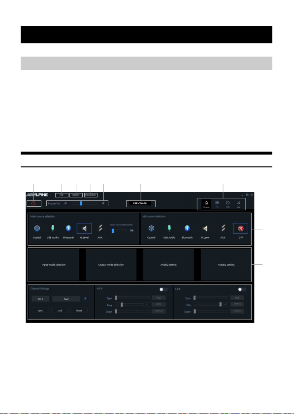
3 Double-click the PXE-C80_C60 software icon
to open the software.
10-EN
Onl ine switch.
Load or save the tuning file.
Sele ct the function setting.
Encr yption and decryption of tuning data.
Adjust th e total volume.
Display the model name.
Function page selection.
E diting area of functio n page.
Page 13
Connection
Setting items:
Connection
Setting content:
Connection/disco nnected
Connection Settings
1 Connect the USB cable and open the
software, it will automatically go online.
After the connection is successful, the
connection icon will show green [ ].
2 After online, click the connection icon to
disconnect. When not online, the connec tion
icon will display red [ ], and click the
connection icon again to go online again.
File Settings
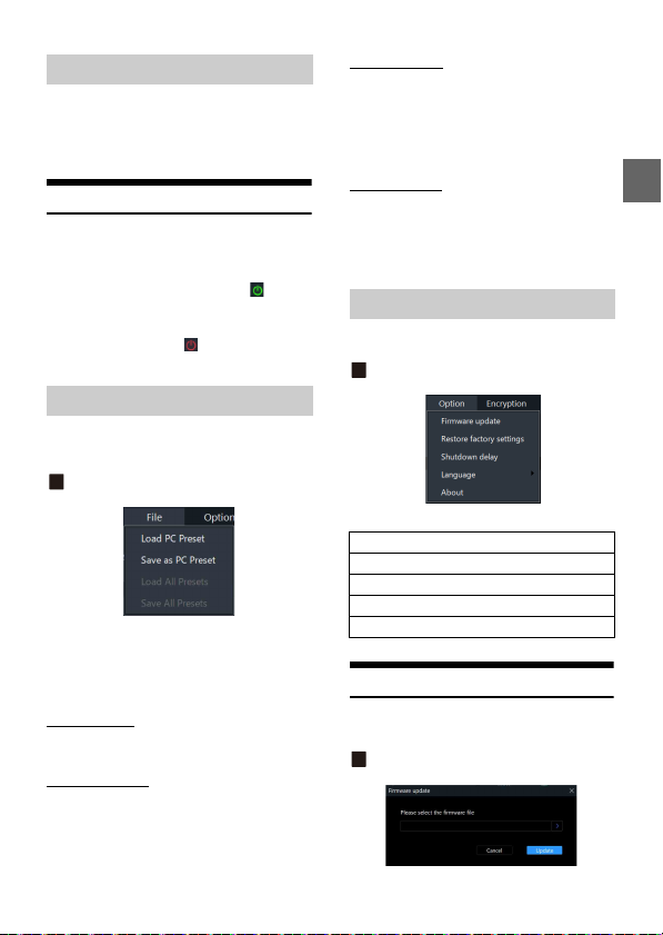
Click [File] to enter the loading or saving scene file
page.
Load or save presets file page
Setting items:
File
Setting content:
Load PC Preset/Save as PC Preset/Load All Presets/
Save All Presets
Load PC Preset
The scene file previously saved on the computer can
be loaded as the current machine working scene.
Save as PC Preset
The current machine work scene file can be saved to
the computer for later recall.
Load All Presets
Load the files of the entire machine previously saved
on the computer to the machine (including the
current working scene, machine preset scene,
output channel configur ation data, etc.), and copy
all the machine data that has been debugged to the
currently connected machine.
Save All Presets
Save all data on the current online machine as a
computer file (including the current working scene,
machine preset scene, output channel configuration
data, etc.) for later recall when the whole machine is
copied.
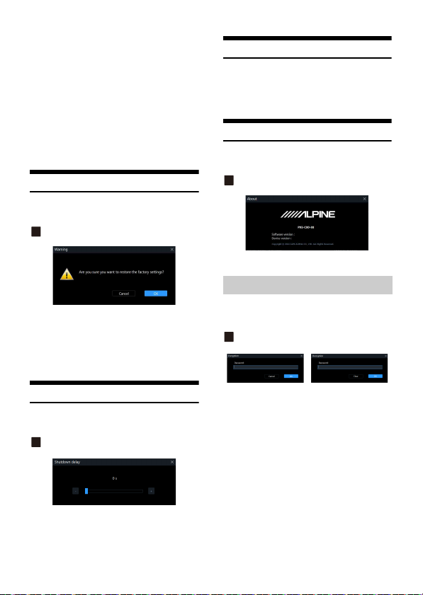
Option Setting
Click [Option] to enter the setting page.
Setting page
<Setting item>
Firmware update
Restore factory settings
Shutdown delay
Language
About
Firmware Update Settings
Select [Firmware Update] from the options page to
enter the firmware update setti ng page.
Firmware update pa ge
11-EN
Page 14
Setting item:
Firmware update
1 Click the “>” button to selec t the upgrade
file.
2 Click the “Update” button to upgrade the
firmware. The upgrade progress reac hes
100%, indicating that the firmware upgrade
is successful.
3 Click the “OK” button to exit the firmware
update. Af ter the upd ate, the mac hine will
automatically restart to work.
Restore Factory Settings
Select [Restore Factory Setting s] from the options
page to enter the factory reset page.
Restore factory settings pa ge
Setting item:
Restore factory settings
1 Click the “OK” button to restore all th e data
set in the machine to the factory default
state.
Language Settings
Setting item:
Language
Setting content:
English
View About
Select [About] from the options page to enter the
about page.
About page
You can view the version number.
Encryption Settings
Click [Encryption] to enter the encryption page, and
click [Decryption] to enter the decry ption page.
Encryption/Decr yption page
Shutdown delay setting
Select [Shutdown Delay] from the options pag e to
enter the shutdown delay setting page.
Shutdown delay page
Setting item:
Shutdown delay
Setting content:
0~255s (initial valu e: 0s)
12-EN
Setting items:
Encryption/D ecryption
1 Encryption: Enter the password to encrypt
the tunin g data.
2 Decr yption: You can enter a pa ssword to
decrypt or clear data to EQ default data.
• Encryption of EQ frequency, Q value, gai n, delay,
channel, phase equalizer and other tuning data.
• Encryption only encrypts a single group of audio
data currently in use, not all data of the whole
machine.
• The encrypted sound data can be stored as preset
sound effects or computer files, and copying and
transmission will not affect the encr ypted state.
Page 15
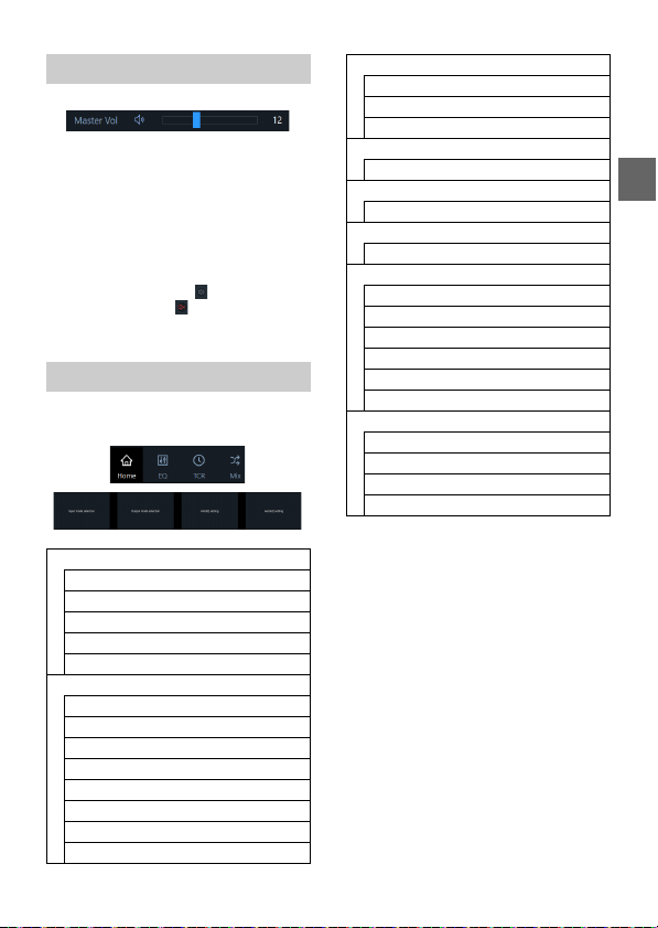
Master volume setting
Setting item:
Master volum e
Setting content:
0~35 (initial value: 12)
1 You can adjust the total volume by pressing
and holding the left mouse b utton, dragging
the volum e fader left or right, or scro lling the
mouse wheel.
2 Click the main volume [ ] button to set the
total volu me mute [ ], clic k again to ca ncel
the mute (i t will automatic ally cancel the
mute when the main volume is adjusted).
Function Page Selection
The function page ca n be switched.
<Setting item>
Home Page
Main source selection
Main source attenuation setting
Mix source selection
Channel settings
X-Over settings
EQ
Channel mute
Sync settings
EQ adjustment
Equalizer settings
Type selec tion
Channel settings
X-Over settings
Preset sound settings
TCR
Delay adjustment
Delay group selection
Delay v alue disp lay window
Mix
Combined frequency volume adjustment
Input mode selection
Input mode selection
Ouput mode selection
Ouput mode selection
Anti EQ
Type s electi on
Fixed
EQ adjustment
Equalizer settings
Signal gain
Sensitivity
AutoEQ
Volume Adjustment
Measurement
Tuning
Managing
13-EN
Page 16
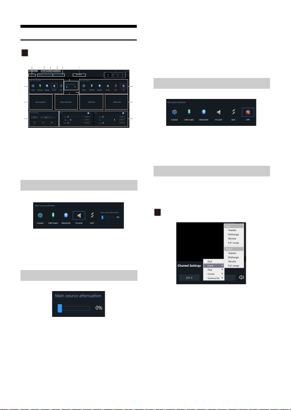
Home Page
Home Page
Setting content:
0% to 100% (default 0%)
Note:
When the current audio source mode is selected,
the audio source mode can no longer be
superimposed, otherwise the Mix source is invalid.
Mix Source Selection
Setting items:
Home Page
Setting content:
Main source selection/Main source attenuation/
Mix source selection/Channel settings/
X-Over settings
Main Source Selection
Setting items:
Main source selection
Setting content:
Coaxial/USB Audio/Bluetooth/Hi.Level/AUX
Main Source Attenuation Setting
You can press and hold the left button of the mouse
to move the fader left or right or scroll the mouse
wheel, or press the up and down keys of the
keyboard to set the attenuation. The Mix source is
equivalent to mixing. The greater the attenuation of
the main sound source, the lower the main volume,
adjustable value: 0%~100%.
Setting items:
Main source attenuation
14-EN
Setting items:
Mix source selection
Setting content:
Coaxial/USB Audio/Bluetooth/Hi.Level/AUX/OFF
Channel Settings
Custom output channel type.
You can configure your favorite channel type
according to your ho bby.
Output type custom page
1 Click the channel type custom box.
2 Select the output channel type in the pop-up
window. Set the output type in the output
type setting dialog box. There are tweeter,
midrange, woofer and full-range options in
the Front; tweeter, midrange, woofer and
full-range options are available in the Rear ;
Front Center, Rear Center, F/C-Tweeter, R/Ctweeter options are available in the Center;
L-subwoofer, R-subwoofer and subwoofer
options are available in the Subwoofer.
Page 17
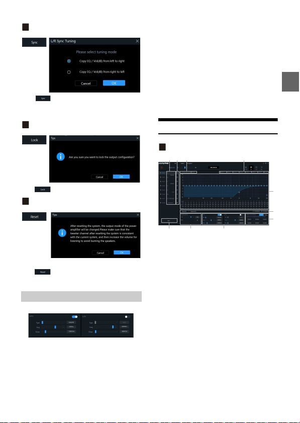
Sync settings page
Click [ ], The optional sync is “Copy EQ/Vol(dB)
from left to right” or “Copy EQ/Vol(dB) from right to
left”.
Lock settings page
2 Frequency setting: The frequency can be
adjusted by directly inputting the value,
scrolling the mouse wheel, the up and down
keys on the keyboard, or cl icking “-” or “+”.
Adjustable range: 20Hz~ 20000Hz.
3 Slope setting: -6dB/Oct, -12dB/Oct, -18dB/
Oct, -24dB/Oct, -30dB/Oct, -36dB/Oct, -42dB/
Oct, -48dB/ Oct is optional.
Note:
When the slope is -6 dB/Oct, the type is displayed as
“Null”.
EQ
EQ page
Click[ ],It will lock all the output channel type.
Reset settings page
Click[ ],It will clear all the output channel type
to Null.
X-Over Setting s
Setting items:
X-Over settings
Setting content:
Type/Frequency/Slope
1 Type settings: Link-Ril, Bessel and Butter-W.
Setting items:
EQ/Channel Settings/X-Over settings/Preset sound
settings
Setting content:
Channel mute/Sync settings/EQ adjustment/
Equalizer settings/Channel display selection
button/Channel s ettings/X-Over setting s/Preset
sound settings
Custom ize the output channel type.
Mu te button.
EQ Gain step selection.
Channel display selection button.
EQ editing and display area.
Eq ualizer settings.
Sync setti ngs button.
Cha nnel settings.
X-O ver settings.
Preset sound settings.
15-EN
Page 18
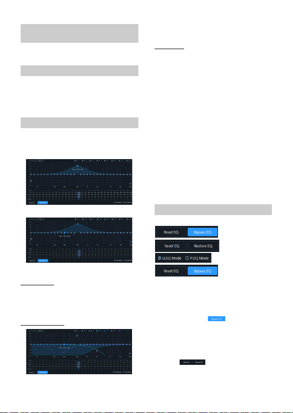
Customize the output channel
P. EG pa g e
G.EQ page
type
Refer to “Output type custom page” (page14 ).
Channel Mute Setting
Setting items:
Channel mute
Setting content:
Mute/off
EQ Adjustment
The output has 31 bands of EQ adjustable, and there
are two interfaces of graphic equalization and
parametric equalization.
Click the channel display selection button to display
the curve of the channel.
EQ settings
1 Select the output channel to be adjusted.
2 When the mouse moves to the serial numb er
position, hold down, drag up an d down to
adjust the equalizer gain, drag left and right
to adjust the equalizer frequency; when the
mouse moves to the left and right blue
boxes, hold down and drag to adjust the
equalizer Q value. You can also set the
frequency, Q value and gain by directly
inputting the value, scrolling the mouse
wheel, and the up and down keys on the
keyboard.
Adjustable frequency range: 20Hz ~20kHz;
Adjustable range of Q value: 0.404~2 8.852;
Gain adjustable range: -12.0 dB ~+12.0 dB.
Note:
The gain is adjustable in the graphic equalization
interface, and the frequency and Q value are not
adjustable. In the parameter equalization interface,
the frequency, Q value and gain are adjustable.
Equalizer Settings
EQ Gain step
Setting items:
EQ Gain ste p
Setting content:
0.1 (initial setting)/ 0.5/1
EQ curve display
16-EN
1 When there is EQ ad justment, the direct
equalization button appears.
2 Through Equalization: When th e current
channel equalizer is turned on, this bu tton
will be displayed [ ], click [Through
Equalization ] or the through dot to make all
equalizers of the current channel inac tive
(through).
3 After clicking the “Yes” button, the button
will be restored to the [Restore Balance ]
state [ ]. Then click [Restore EQ]
and all equalizers of the current chann el will
return to the last activated state.
Page 19
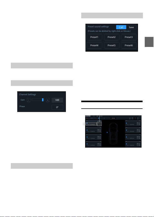
4 Click [Reset EQ], the p arameters of all
equalizers of the current channel retu rn to
the initial state.
5 Click [G.EQ Mode] to pop up a warning box
“Confirm P.EQ to G.EQ mode?”, press OK to
switch to [G.EQ Mode], click [P.EQ Mode] to
pop up a warning box “Confirm G.EQ to P.EQ
mode?”, press OK to confirm Switch [P.EQ
Mode]. In the parametric equalization mode,
the frequency, Q value and gain are
adjustable, while in the graphic equalizer
mode, the frequency and Q value are fixed,
and only the equalizer gain can b e adjusted.
Sync Settings
Refer to “Sync settings page” (page 15).
Channel settings
Setting items:
Preset sound settings
Setting content:
Gain/phase
1 Gain setting: The gain can be adjusted by
directly inputting the value, scrolling the
mouse wheel, the up and down keys on the
keyboard, or clicking “-” or “+”. Adjustable
range : -60dB~ 6dB.
2 Phase setting: norma l phase or reverse
phase switch.
X-Over settings
Refer to “X-Over Settings” (page 15).
Preset sound settings
Setting items:
Preset sound settings
Setting content:
Call/Save/Delete
1 Click [Call] to recall the pre -stored sound
effects.
2 Click [Save] to store the a djusted sound
effect dat a.
3 Click the right mouse button to delete the
preset sound settings.
TCR
De lay adjustment.
Delay group selection.
Delay value display window.
Setting items:
Delay set ting
Setting content:
Delay/Delay group
1 Delay adjustment: The delay can be adjusted
by directly inputting the value, scrolling the
mouse wheel or the up and down keys on the
keyboard.
2 Delay group: select the delay group, and the
channels with the same delay group can be
adjusted together.
17-EN
Page 20
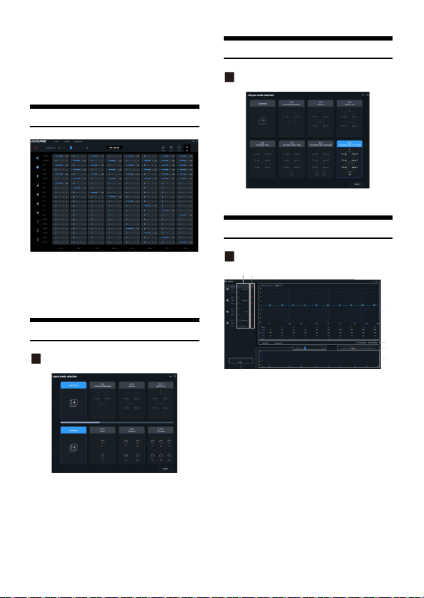
3 The delay units are ms (milliseconds), inch
(inches) and cm (centimeters).
Delay range: 0.000~20.000 milliseconds;
0~692 cm;
0~273 inches.
Mix
Output mode selection
Output mode selection page
Refer to “Input mode selection page” (page 18).
Anti EQ
After the PXE-C80-88 machin e sets the sound source
signal into the audio processor, it is divided into the
volume of each output channel, and the purpose of
mixing and mixing can be achieved by adjusting the
volume of each so und source in the channel.
Input mode selection
Input mode selec tion page
1 Select the des ired channel type.
2 Click the [Enter] button to configure the
channel type. At this time, the input channel
type is fixed and cannot be configured.
3 Select Customized to clear all input channel
types. At this time, you can customize the
input channel types.
18-EN
AntiEQ page
Setting items:
Anti EQ
Setting content:
Fixed/EQ adjustment/Equalizer setting/Save/
Signal gain/Sensitivity
Hi.Level input channel type.
Fixed the R TA data.
EQ editing and display area.
Eq ualizer settings.
Save the AntiEQ data.
Si gnal gain.
Sensitivity.
RTA data.
Page 21
H.level input channel type
Figure 1
Refer to “Output type custom page” (page14 ).
Fixed the RTA data
1 Default is Fixed [ ], There is no RTA data.
2 Click one channe l Unfixed [ ], be gin to
display RTA data.
3 10 bands of EQ adjustable to make the RTA
data is flat.
EQ Adjustment
Refer to “EQ Adjustment” (page 16).
Equalizer settings
Refer to “Equalizer Settings” (page 16).
Signal gain
Hold down the mouse and push the fader left and
right to adjust the signal gain.
Sensitivity
There are high, medium and low options. The higher
the sensitivity, the more sensitive the frequency
spectrum jumps.
AutoEQ
The PC and amp will connect automatically.
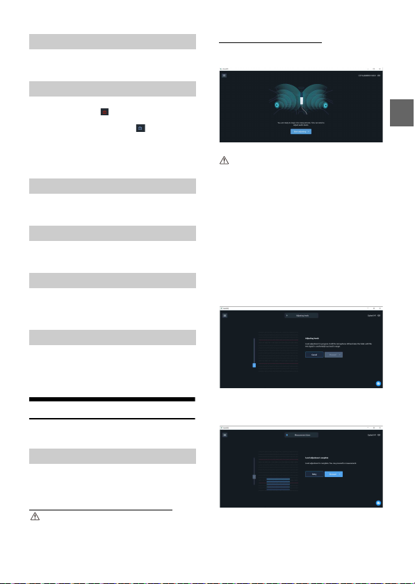
Volume adjustment process
Upon connecting to a new amp, AutoEQ will prompt
you to start adjusting the volume level.
Important:
Make sure the microphone is connected to the amp.
Hold the microphone in the center of the cabin
about one foot from the center console.
Click the button to proceed when you are ready.
You will hear the frequency sweep (“whoopwhoop”) playing at a low volume.
Use the volume slider on the screen to gradually
raise the volume until the input level rises to the
middle of the volume monitor.
AutoEQ will automatically stop playing the signal
after it detects a good level for a few seconds.
With level adjustment complete, the app will
prompt you to proceed to the next step:
measurement.
Figure 2 - The volume adjustment screen showing
the starting volume for the volume adjustment
process.
Volume Adjustment
Before measurement, the application will help you
set an ideal volume.
Neutralize tone controls and processes
Important:
Be sure at this point to neutralize any tone controls
and turn off any sound processes which are
downstream from the amp.
Figure 3 - The volume adjustment screen showing
the end result of volume adjustment.
The slider has been raised and the detected volume
is optimal.
19-EN
Page 22
Measurement
This section explains the measurement portion of
AutoEQ.
Microphone movement
Correct microphone movement during sound
measurement is critical to getting a good result from
AutoEQ. Please read this section carefully.
1 Overview
To make a measurement, you will move the
microphone through the space of the cabin while
AutoEQ plays a frequency sweep (“whoop-whoop”
sound).
The key is to move the microphone constantly and
consistently so that all of the space in the cabin is
evenly covered during measurement.
This is important, so we will explain it in detail.
2 Measurement points
One AutoEQ measurement consists of at least 200
measurement points. That is, the frequency sweep
(“whoop-whoop”) will be played 200 times in order
to measure the cabin’s sound.
The exact point in space where the microphone is
when it hears one frequency sweep is a
measurement point. The sound was measured at
that point.
The goal of microphone movement is to space these
measurement points as evenly as possible in the
frontal space of the car cabin.
3 Range of movement
Spaces through which you should move the
microphone include:
• The space above the dashboard.
• The space in front of the driver and passenger, as
low as the front of their shins (going slightly into
the foot wells) and as high as the ceiling.
4 What to avoid
When moving the microphone for a measurement:
• Do not stop moving the micro phone at all,
including for individual measurement points.
Constant movement is best.
• Do not go deep into the foot well spaces in the
measurement.
Perform measurement
When you are ready, click the button to begin
measurement.
A countdown will begin on the screen, and then the
measurement process will begin.
For the duration of the measurement, move the
microphone through the cabin of the car as
described in the previous section.
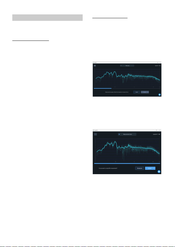
During measurement, the result of each sweep will
be displayed on the screen with a faint curve and
the average will be shown with a strong curve.
Figure 4 - The measurement screen showing a
measurement in progress.
The progress of the entire measurement will be
shown in a progress bar at the bottom of the screen.
The app will confirm when measurement is
completed.
Figure 5 - The measurement screen showing a
measurement that has been completed.
If you see no obvious problems with t he
measurement, you can accept it. If not, choose
“remeasure” to retry measurement.
20-EN
Page 23
Tuning
With measurement complete, you are ready to tune
the sound in the vehicle.
Tuning screen
This section is an introduc tion to the tuning screen.
It will cover the controls shown on the screen
without discussing procedure.
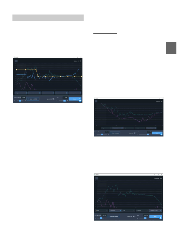
Figure 6 - The tuning screen with its default options
shown.
1 Side Pa nel Controls
These are the controls available outside of the main
graph area:
EQ Gain Offs et - This setting adjusts the boost and
cut of the EQ. This will be the first s tep in your tuning
process.
Reset to Default - This button resets everything on
this tuning screen to defaults.
Bypass EQ - This toggle allows you to A/B test the
sound with the EQ on and off.
Level - This slider controls the volume of the music
source.
2 Graph Curves
These are the curves shown in the main graph area.
The display of each one can be toggled on and off.
Target (yellow) - This is the curve which you will
manipulate to tune the system. AutoEQ will match
your system’s sound to this curve.
Measurement (dark teal) - This is the measured
APVD of your car’s system.
EQ (blue) - This is the correction curve AutoEQ will
apply in order to achieve your target curve.
Predicted (g ray) - This curve shows what the
predicted result from your target curve will be.
It will vary slightly from the target (yellow) curve, or
may be hidden behind it if AutoEQ is going to hit
your target exactly.
Distortion & Noise (mag enta) - This curve shows
the distortion and noise that were present during
your measurement.
Tuning Process
This section covers the standard procedure using
the tuning screen to create your EQ.
1 Check the Distortion & Noise Level
Before proceeding, we must check the Distortion &
Noise curve relative to the Measurement curve. To
make this easier, you may turn off display of all other
curves.
Where the Distortion & Noise curve comes too close
to the Measurement curve, that means there is too
much noise to rely on this measurement in that
frequency range. The Distortion & Noise curve
should be at least 10 dB below the M easurement
curve. If it is 6 dB or closer, that frequency range of
the measurement is unreliable.
Figure 7 - The tuning screen showing an
unacceptable high amount of noise.
It is expected that the Distortion & Noise curve will
approach the Measurement curve in the very low
frequency ranges. This will be in the frequency
range where ambient noise overpowers the system’s
capabilities. This is not a problem.
Figure 8 - The tuning screen sho wing a good noise
level, well below the measurement curve.
21-EN
Page 24
2 Adjust the EQ Gain O ffset
This setting will define the amount of boost and cut
AutoEQ w ill use.
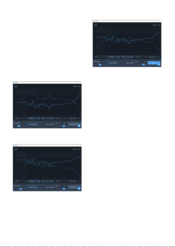
When adjusting EQ Gain Offset, it is best to turn on
the display of only the Measurement and EQ curves
in the graph area. This way, you can clearly see the
boost/cut areas.
•Boosted areas are the frequency ranges where
the EQ curve is above the Measurement curve.
•Cut areas are the frequency ranges where the EQ
curve is below the Measurement curve.
Use the slider to raise or lower the EQ Gain Offset
until there is an equal amount of boost and cut
across the graph.
Bad of fset sampl e Figure 9, Fig ure 10.
Figure 9 - The tuning screen showing an EQ G ain
Offset with too much cut. The EQ curve is entirely
below the Measurement curve.
Figure 10 - The tuning screen showing an EQ Gain
Offset with too much boost. The EQ curve is entirely
above the Measurement curve.
Good offset sample Figure 11.
Figure 11 - The tuning screen showing an EQ Gain
Offset that is good. It is balanced between cut and
boost.
3 Play reference a udio
If you want to play reference aud io while tuning, you
can start now. You can play audio from a music
player app on your PC, or you can send audio into
the amp from a completely separate input. Both will
work for real-time tuning.
4 Adjus t the Target Curve
Enable the display of the Target curve. (Displaying
other curves is optional.) This is the yellow curve
with control points which you can set to define your
desired outcome. Each control point is represented
as a node (white dot) on the curve.
Moving the control points - To move a control
point, simply drag it to the desired location. You can
move it side to side or up and down.
Adding a control point - To add a control point,
double-tap on the Target curve where you want to
create the new point. Then, drag that point to adjust
its position.
Deleting a control point - To delete a control point,
double-top on it. You will have an option to delete
that control point, or to cancel deletion.
As you modify the target c urve, AutoEQ will update
the EQ curve and send it to th e amp so you can hear
your result. There is a delay of a few seconds from
when you make an adjustment to when you hear it
from the system.
5 Storin g the EQ Curve
When you are done adjusting your target curve, you
can click the Store button to finalize the EQ curve on
the amp.
The EQ data is now saved on the amp.
22-EN
Page 25

Managing Amps
This sect ion covers how to manage saved am ps in
AutoEQ and how to reconnect to an amp you have
already worked on.
Reconnect to an amp
To reconnect to an amp you have worked on
previously, you must have that amp connected to
your PC via USB. The amp will appear in the Recently
connected list. To work on this amp, simply click on
its name.
Rename an amp
It is strongly recommended to give an amp a name
that is easy to remember. To rename an amp from
the Recently connected amps li st, click on the threedot menu icon on the right side of its name. Choose
“Edit.”
You can now rename the amp by changing the
name in the text field. The original name of the amp
will always be saved and shown in the amp info.
Remove an amp
To remove an amp from th e Recently connected list,
tap on the three-dot menu icon on th e right side of
its name. Choose “Edit.”
Click the button at the bottom of the menu to
remove the amp from your app.
23-EN
Page 26
Mobile Phone App
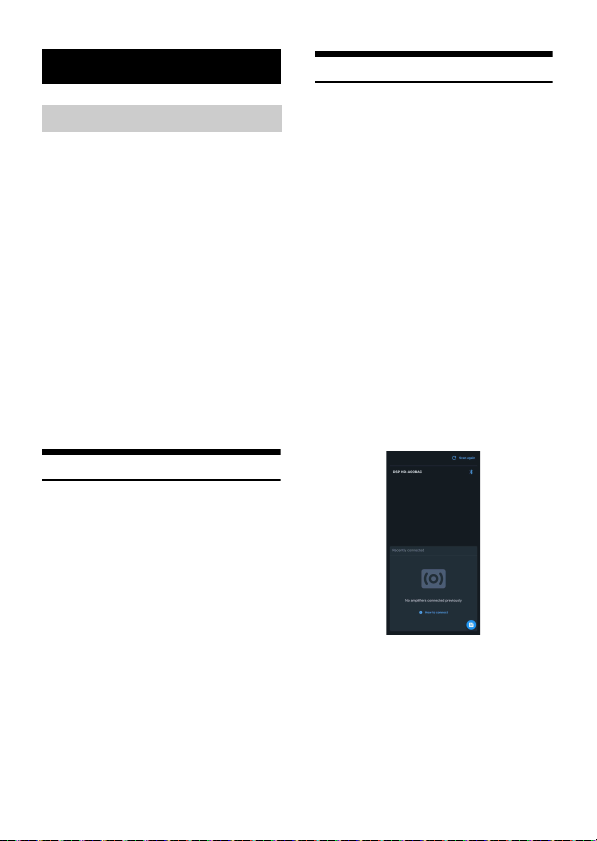
Figure 1
Overview
This manual explains how to use the Alpine AutoEQ
app on an iPhone to perform equalization.
Here is an overview of the process:
1 Setup
A list of required software and hardware.
2 Connect
Connect the iPhone app to the Alpine amp.
3 Volume adjustment
The app will assist you in setting the right volume
for measuremen t.
4 Measurement
You will move the iPhone throughout the cabin i n a
specific way while the amp plays frequency sweeps.
This measures the sound in the cabin.
5 Tuning
Once you have an accurate measurement, you can
tune the system using the graphical interface.
Setup
This sect ion covers the r equired hardw are and
software for using Alpine AutoEQ.
1 Hardware
Necessary hardware includes:
•Alpine amp
• An iPhone with access to the App Store
2 Software
The Alpine AutoEQ app is available from the App
Store. Open the App Store and search for
“PXE-C80_C60.” Be sure to select the app published
by Alpine Electronics.
Connect
Follow the instructions below to connect the Alpine
AutoEQ app to the amp.
1 Tu rn o n th e am p
Power on the Alpine amp. Make sure its Bluetooth
dongle is plugged in.
2 Bluetooth Settings on iPhone
From the iPhone’s home screen, open the Settings
app.
Tap on Bluetooth to enter the Bluetooth settings.
In the list of available devices, you will see the Alpine
amp. It will have a name that starts with “DSP HD…”. Tap on this option to connect your phone to the
amp.
3 Open the app a nd connect
From the iPhone's home screen, open the Alpine
AutoEQ a pp.
When the app opens, it will scan for Alpine amps.
In the upper portion of the screen, it will show new
amps you have not connected to.
The Recently connected panel in the lower part of
the screen shows amps you have connected to
previously.
Tap on the amp you want to connect to.
24-EN
Page 27
Volu me Adjustment
Refer to AutoEQ Volume Adjustment in PC side.
(page 19)
Tuning
Refer to AutoEQ Measurement in PC side. (page 21)
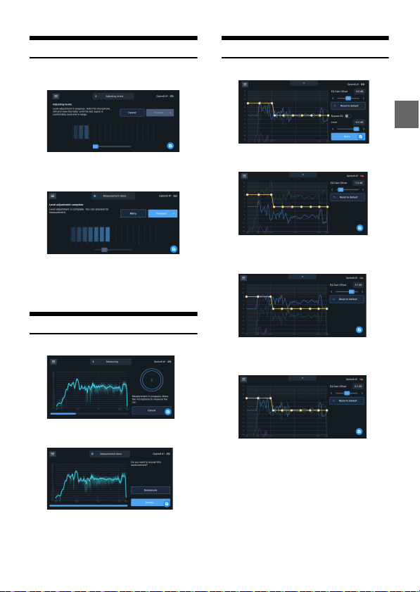
Figure 2 - The volume adjustment screen showing
the starting volume for the volume adjustme nt
process (horizontal orientation).
Figure 3 - The volume adjustment screen showing
the end result of volume adjustment.
The slider has been raised and the detected volume
is optimal. (Horizontal orientation.)
Measurement
Refer to AutoEQ Measurement in PC side. (page 20)
Figure 4 - The measurement screen showing a
measurement in progress.
Figure 5 - The measurement screen showing a
measurement that has been completed.
Figure 6 - The tuning screen with its default options
shown.
Figure 7 - The tuning screen showing an EQ Gai n
Offset with too much cut. The EQ curve is entirely
below the Measurement curve.
Figure 8 - The tuning screen showing an EQ Gai n
Offset with too much boost. The EQ curve is entirely
above the Measurement curve.
Figure 9 - The tuning screen showing an EQ Gai n
Offset that is good. It is balanced between cut and
boost.
25-EN
Page 28
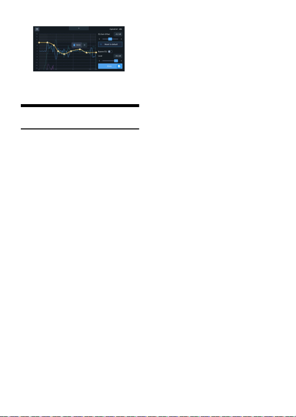
Figure 10 - An example of the tuning screen
showing a customized EQ curve with the option
shown to delete a control point.
Managing Amps and Reconnecting
Refer to Aut oEQ Managing Amps in PC side.
(page 23)
26-EN
Page 29
Wired Controller
Figure 1
Figure 2-1
Figure 2-2
Figure 3
Figure 4-1
Connect the wired controller (RUX-CSP1) to the DSP
correctly, and ensure that it starts normally before
use.
Startup Screen
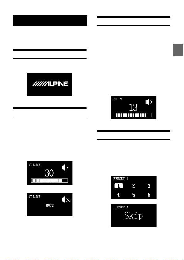
After the wired controller is started, the dynamic
startup screen appears, as shown in Figure 1.
Master Volume
After it is started, enter the main interface of the
wired controller-Master Volume Interface, as shown
in Figure 2-1. Turn the button to adjust the master
volume. Turning it clockwise can increase the
volume, while turning it counterclockwise will
decrease the volume. The adjustment range is from
0 to 35. In addition, pressing the master volum e
interface of the wired cont roller briefly can mute the
DSP. The mute interface is as shown in Figure 2-2.
Subwoofer Volume (SUB W)
Press and hold the button in the main interface for
1~4 seconds to enter the subwoofer volume (SUB
W) interface, as shown in Figure 3. Turn the button
of the wired controller to adjust the subwoofer
volume. Turning it clockwise can increase the
volume, while turning it counterclockwise will
decrease the volume (Adjustment range: 0~15).
When the volume is turned to the desired volu me,
press the button briefly to determine the selec ted
volume, and then return to the main volume
interface directly.
Note:
If the wired controller is not operated for about
4 seconds, it will exit from the interface to the main
interface (Master Volume Interface).
Sound Effect Presets (PRESET)
Press and hold the button in the main interface for
over 4 seconds to enter the sound effect presets
interface. And then turning the button to move the
cursor to the sound array “1~6” or enter the “Skip”
page, as shown in Figure 4-1. The number after
PRESET refers to the sound effect data currently
used by the DSP.
27-EN
Page 30
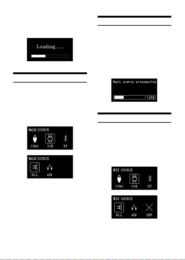
When the cursor moves to a number, press the
Figure 4-2
Figure 5
Figure 6
Figure 7-1
button briefly to load the sound effect presets, as
shown in Figure 4-2. After the data is loaded, it will
exit from this interface to the main interf ace (Master
Volume Interf ace).
Main Source
Turn the button of the wired controller in the “Skip”
interface to enter the main source interface, as
shown in Figure 5. Turn the button to select the
main sound source: COAX (Digital), USB, BT
(Bluetooth), Hi.L (High Level), or AUX (Low Level),
and press the button briefly to confirm the main
source selection mode. If no operation is performed
for about 4 seconds, it will exit from the interface to
the main interface (Master Volume Interface).
Main Source Attenuation
Press the button briefly to select the COAX (Digital),
USB, BT (Bluetooth), Hi.L (High Level), or AUX (Low
Level) mode to enter the interface of adjusting the
main source attenuation, as shown in Figure 6. Turn
the button to adjust the main source attenuation
level, clockwise is to increase the attenuation level,
while turning it counterclockwise will decrease the
attenuation level. The range of attenuation is
0~100%. If no opera tion is performed for about 4
seconds, it will exit from the interface to the main
interface (Master Volume Interface).
Mix Source
After pressing the button to select the main source
attenuation, you can enter the mix sound source
interface, as shown in Figure 7-1. Turn the button to
select the mix sound source: COAX (Digital), USB, BT
(Bluetooth), Hi.L (High Level), AUX (Low Level) or
OFF. And press the button briefly to confirm the mix
source mode. If no operation is performed for about
4 seconds, it will exit from the interface to the main
interface (Master Volume Interface).
28-EN
Page 31
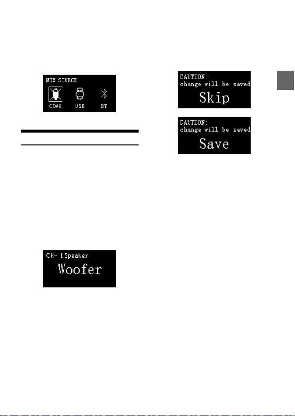
Note:
Figure 7-2
Figure 8-1
Figure 8-2
When a sound source is selected, it cannot then be
selected again as the mix sound source; doing so
causes t he mix sound source to be invalid, as sh own
in Figure 7-2. If no operation is performed for about
4 seconds, it will exit from the interface to the main
interface (Master Volume Interface).
Channel Settings
Press the button briefly to select the COAX (Digital),
USB, BT (Bluetooth), Hi.L (High Level), AUX (Low
Level) or OFF mode to enter the channel settings
interface, as shown in Figure 8-1. The output type of
channel 1 sp eaker can be se lected by turning the
button in the following order: Full-range, Tweeter,
Woofer, Subwoofer, and M id-range. After selection,
press the button briefly to confirm the channel typ e.
And if CH-1 is synchronized to the Tweeter type, it
will be displayed. Then turn the button to the right
to select the speaker type in the order of Woofer
Subwoofer Mid-rang, and turn the button to the
left for Full-rang. At the same time, press the button
briefly can also be directly switched to 2~8 channel,
and the corresponding channel settings.
When the wire controller is in the channel 8 setting
interface, press the button briefly to enter the
CAUTION page, as shown in Figure 8-2. Turn the
button can choose to save or skip, and press it
briefly to determine the selection. Afte r the
selection is complete, it will automatically exit from
the interface to th e main interface.
29-EN
Page 32

Information on the disposal of waste electrical and electronic equipment and batteries (applicable to
countries that adopt a garbage collecti on system)
If you want to dispose of this product, do not mix it with general ho usehold waste. In accordance with
regulations that require proper disposal, recycling and recycling, there is a separate collection system for waste
electronic products. Please contact your local authori ties to find the location of the recycling facility closest to
you. Proper recycling and waste disposal help conserve resources while preventing harmful effects on human
health and the environment.
30-EN
Page 33
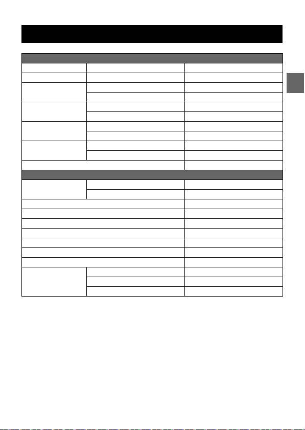
Specifications
Perfo rmanc e
Power Output Rated: 4Ω, 14.4V, 10%TH D CH1-6: 50W, CH7-8: 150W
RCA Output Rated: 10kΩ, 14.4V, 0.1%THD CH1-8: 4Vrms
THD+N High level: 2Vrms into 4Ω ≤0.1%
S/N High level: 40k-AES17+A-weighted ≥80dB
Input Voltage High level 26Vpp
Output Voltage High level CH 1-6: 40Vpp, CH7-8: 70Vpp
Frequency Response 20Hz~40kHz
General
Input Impedance High level >50kΩ
System Sampling Rate 192kHz/32bit
Operating Voltage 9~16V
Operating Temperature -20°C~+60°C
BACK UP CURRENT (12.6V) ≤3mA
REM Start Input High level (H1-/H1+), ACC optional
REM Start Output 12V (0.2A)
Weight 2.4kg
Dimensions Length 225mm
RCA: 2Vrms into 10kΩ ≤0.06%
RCA: 40k-AES17+A-weighted ≥95dB
RCA 11Vpp
RCA 4Vrms
RCA >50kΩ
Width 220.5mm
Height 54mm
31-EN
Page 34

Function Parameter
Inputs 8ch High-level
Outputs 8ch High-level
Output Channel Signal Gain Range: -60dB~+6dB
Output Signal Equalizer Type: Parametric / Graphic Equalizer
Anti EQ S ignal Equalize r Type: Parametr ic / Graphic Equ alizer
Output Signal Divider Each output channel is equipped with multi-order high and low pass
Output Phase Normal phase or reverse phase (0° or 180°)
Output Delay 0.000~20.000ms, 0~692cm, 0~273inch
Preset Sound Effects 6 sound data presets
6ch RCA
Coaxial Digital Signal
Bluetoot h Audio
USB Audio (DAC)
8ch RCA
Frequency: 20Hz~20kHz (1Hz step s)
Q value: 0.404~28 .852
Gain: -12.0dB~+12.0dB (0.1dB steps)
Frequency: 20Hz~20kHz (1Hz step s)
Q value: 0.404~28 .852
Gain: -12.0dB~+12.0dB (0.1dB steps)
indepe ndent filters,
Filter type: Link-Ril, Bessel, Butter-W
Filter crossover point: 20Hz~20kHz (1Hz steps)
Filter slope: -6dB/Oct~-48dB/Oct
32-EN
Page 35

Open Source License
Apache Lice nse
Version 2.0, January 2004
http://www.apache.org /licenses/
TERMS AND CONDITIONS FOR USE, REPRODUCTION, AND DISTRIBUTION
1. Definitions.
“License” shall mean the terms and condi tions for use, reproduction, and distr ibution as defined by
Sections 1 through 9 of this document.
“Licensor” shall mean the copyright owner or entit y authorized by the copyrig ht owner that is granting
the License.
“Legal Entit y” s hall mean the union of th e acting entity and a ll other entities that co ntrol, are controlled
by, or are under common control with that entity. For the purposes of this definition, “control” means (i)
the power, direct or indirec t, to cause the direction or mana gement of such entity, whether by contra ct
or otherwise, or (ii) ownership of fifty percent (50%) or more of the outstanding shares, or (iii) beneficial
ownership of such entity.
“You” (or “Your”) shall mean an individual or Legal Entity exercising permissions granted by this License.
“Source” form shall mean the preferred form for making modificat ions, including but not limite d to
software source code, documentation source, and configuration files.
“Object” form shall mean any form resulting from mechanical transformation or translation of a Source
form, including but not limited to compiled object code, generated documentation, and conversions
to other media types.
“Work” shall mean the work of authorshi p, whether in Source or Object form, made available under the
License, as indicated by a copyright notice that is included in or attached to the work (an example is
provided in the Appen dix below).
“Derivative Works” shall mean any work, whether in Source or Object form, that is based on (or derived
from) the Work and for which the editorial revisions, annotations, elaborations, or other modifications
represent, as a whole, an original work of authorship. For the purposes of this License, Derivative Works
shall not include work s that remain separable from, or merely link (or bind by nam e) to the interfaces
of, the Work and Derivative Works thereof.
33-EN
Page 36

“Contribution” shall mean any work of authorship, including the original version of the Work and any
modification s or additions to that Work or Derivativ e Work s thereof, that is intentionall y submitted to
Licensor for incl usion in the Work by the copyright ow ner or by an individual or Lega l Entity authorized
to submit on behalf of the copyrig ht owner. For the purposes of this definition, “submitted” means any
form of electronic, verbal, or written communication sent to the Licensor or its representatives,
including but not limited to communication on electronic mailing lists, source code control systems,
and issue tracking systems that are managed by, or on behalf of, the Licensor for the purpose of
discussing and improving the Work, but excluding communication that is conspicuously marked or
otherwise designated in writ ing by the copyright owner as “Not a Cont ribution.”
“Contributor” shall mean Licensor and any individual or Legal Entity on behalf of whom a Contribution
has been received by Licensor and subsequently incorporated within the Work.
2. Grant of C opyright License.
Subject to the terms and conditions of this License, each Contributor hereby grants to You a perpetual,
worldwide, non-exclusive, no-charge, royalty-free, irrevocable copyright license to reproduce, prepare
Derivative Works of, publicly display, publicly perform, sublicense, and distribute the Work and such
Derivative Works in Source or Object form.
3. Grant of Patent License.
Subject to the terms and conditions of this License, each Contributor hereby grants to You a perpetual,
worldwide, non-exclusive, no-charge, royalty-free, irrevocable (except as stated in this section) patent
license to make, have made, use, offer to sell, sell, import, and otherwise transfer the Work, where such
license applies only to those patent claims licensable by such Contributor that are necessarily infringed
by their Contribution(s) alone or by combination of their Contribution(s) with the Work to which such
Contributio n(s) was submitted. If You institute paten t litigation against any enti ty (including a crossclaim or counterclaim in a lawsuit) alleging that the Work or a Contribution incorporated within the
Work constitutes direc t or contributory patent in fringement, then any patent licen ses granted to Yo u
under this License for that Work shall terminate as of the date such litigation is filed.
4. Redistribution.
You may reproduce and distribute copies of the Work or Derivative Works thereof in any medium, with
or without m odifications, and in Sou rce or Object form, prov ided that You meet the following
conditions:
(a) You must give any other recipients of the Work or Derivative Works a copy of this License; and
(b) You must cause any modified files to carry prominent notices stating that You changed the files; and
(c) You must retain, in the Source form of any De rivative Works that Yo u distribute, all copyright, patent,
trademark, and attribution notices from the Source form of the Work, excluding those notices that do
not pertain to any part of the Derivative Works; and
34-EN
Page 37

(d) If the Work includes a “NOTICE” text file as part of its distribution, then any Derivative Works that You
distribute must include a readable copy of the attribution notices contained within such NOTICE file,
excluding those notices that do not pertain to any part of the Derivative Works, in at least one of the
following places: within a NOTICE text file distributed as part of the Derivative Works; within the Source
form or documentati on, if provided along with the Derivative Works; or, within a dis play generated by
the Derivative Works, if and wherever such third-party notices normally appear. The contents of the
NOTICE file are for informational purposes only and do not modify the License. You may add Your own
attribution notices within Derivative Works that You distribute, alongside or as an addendum to the
NOTICE text from the Work, provided that such additional attribution notices cannot be construed as
modifying the License.
You may add Your own copyright st atement to Your modifications and may provide additional or
different license te rms and conditions for use, reproducti on, or distribution of Your modifications, or for
any such Derivative Works as a whole, provided Your use, reproduction, and distribution of the Work
otherwise complies with the conditions stated in this License.
5. Submissi on of Contributions.
Unless You explicitly state otherwise, any Contribution intentionally submitted for inclusion in the Work
by You to the Licensor shall be under the terms and conditions of this License, without any additional
terms or conditions. Notwithstanding the above, nothing herein shall supersede or modify the terms of
any separate license agreement you may have executed with Licensor regarding such Contributions.
6. Trademarks.
This License does not grant permission to use the trade names, trademarks, service marks, or product
names of the Licensor, except as required for reasonable an d customary use in describing the origin of
the Work and reproducing the content of the NOTICE file.
7. Disclaimer of Warranty.
Unless required by applicable law or agreed to in writing, License or provides the Work (and each
Contributor prov ides its Contributi ons) on an “AS IS” BASIS, WITHOUT WARRANTIES OR CONDITIONS OF
ANY KIND, either express or implied, including, without limitation, any warranties or conditions of
TITLE, NON-INFRINGEMENT, MERCHANTABILITY, or FITNESS FOR A PARTICULAR PURPOSE. You are solely
responsible for deter mining the appropriateness of using or redistributing t he Work and assume any
risks associated with Your exercise of permissions under this License.
8. Limitation of Liability.
In no event and under no legal the ory, whether in tort (including negligence) , contract, or other wise,
unless required by applicable law (such as deliberate and grossly negligent acts) or agreed to in writing,
shall any Contributor be liable to You for damages, including any direct, indirect, special, incidental, or
consequential damages of any character arising as a result of this License or out of the use or inability
to use the Work (including but not limited to damages for loss of goodwill, work stoppage, computer
failure or malfunction, or any and all other commercial damages or losses), even if such Contributor has
been advised of the possibility of such damages.
35-EN
Page 38

9. Accepting Warrant y or Additional Liabi lity.
While redistributing the Work or Derivative Works thereof, You may choose to offer, and charge a fee
for, acceptance of suppor t, warranty, indemnity, or oth er liability obligations and/o r rights consiste nt
with this License. However, in accepting such obligations, You may act only on Your own behalf and on
Your sole responsibility, not on beh alf of any other Contributor, and only if You agree to indemnify,
defend, and hold each Contributo r harmless for any liability incurred by, or claims asserted against,
such Contributor by reason of your accepting any such warranty or additional liability.
END OF TERMS AND CONDITIONS
APPENDIX: How to apply the Apache License to your work.
To apply the Apache License to your work, attach the following boilerplate notice, with the fields
enclosed by brackets “[]” replaced with your own identifying information. (Don’t include the brackets!)
The text should be enclosed in the appropriate comment syntax for the file format. We also
recommend that a file or class name and description of purpose be included on the same “printed
page” as the copyright notice for easier identification within third-party archives.
Copyright [yy yy] [name of copyright ow ner]
Licensed under the Apache License, Version 2.0 (the “License”);
you may not use this file except in compliance with the License.
You may obtain a copy of the License at
http://www.apache.org/li censes/LICENSE-2.0
Unless required by applicable law or agreed to in writing, software
distributed under the License is distributed on an “AS IS” BASIS,
WITHOUT WARRANTIES OR CONDITIONS OF ANY KIND, either express or implied.
See the License for the specific language governing permissions and
limitations under the License.
36-EN
Page 39

The MIT License
===============
Copyright (c) 2016-2017 ZeroMQ community
Copyright (c) 2016 VOCA AS / Harald Nøkland
Copyright (c) 2009-2011 250bpm s.r.o.
Copyright (c) 2011 Botond Ballo
Copyright (c) 2007-2009 iMatix Corporation
Permission is h ereby granted, free of charge, to any person obtaining a copy of this soft ware and
associated documentation files (the “Software”), to deal in the Software without restriction, including
without limitat ion the rights to use, copy, modify, merge, publish, distribute, subl icense, and/or sell
copies of the Software, and to permit persons to whom the Software is furnished to do so, subject to
the following conditions:
The above copyright noti ce and this permission notice shal l be included in all copies or substanti al
portions of the Software.
THE SOFTWARE IS PROVIDED “AS IS”, WITHOUT WARRANTY OF ANY KIND, EXPRESS OR IMPLIED,
INCLUDING BUT NOT LIMITED TO THE WARRANTIES OF MERCHANTABILITY, FITNESS FOR A PARTICULAR
PURPOSE AND NONINFRINGEMENT. IN NO EVENT SHALL THE AUTHORS OR COPYRIGHT HOLDERS BE
LIABLE FOR ANY CLAIM, DAMAGES OR OTHER LIABILITY, WHETHER IN AN ACTION OF CONTRACT, TORT
OR OTHERWISE, ARISING FROM, OUT OF OR IN CONNECTION WITH THE SOFTWARE OR TH E USE OR
OTHER DEALINGS IN THE SOFTWARE.
37-EN
Page 40
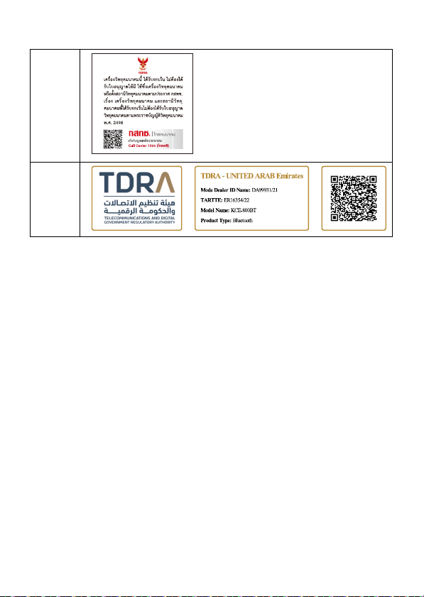
About the Rules of Blueto oth Electromagnetic Radiation R egulation
Thailan d
UAE
38-EN
Page 41

USA/
FCC Statement:
This device complies with Part 15 of the FCC Rules. Operation is subject to the following two conditions: (1) this device may
not cause harmful interference, and (2) this device must accept any interference received, including interference that may
cause undesired operation. Changes or modifications to this unit not expressly approved by the party responsible for
compliance could void the user’s authority to operate the equipment.
NOTE: This equipment has been tested and found to comply with the limits for a Class B digital device, pursuant to Part 15
of the FCC Rules. These limits are designed to provide reasonable protection against harmful interference in a residential
installation. This equipment generates uses and can radiate radio frequency energy and, if not installed and used in
accordance with the instructions, may cause harmful interference to radio communications. However, there is no guarantee
that interference will not occur in a particular installation. If this equipment does cause harmful interference to radio or
television reception, which can be determined by turning the equipment off and on, the user is encouraged to try to correct
the interference by one or more of the following measures:
-- Reorient or relocate the receiving antenna.
-- Increase the separation between the equipment and receiver.
-- Connect the equipment into an outlet on a circuit different from that to which the receiver is connected.
-- Consult the dealer or an experienced radio/TV technician for help.
This device and its antenna(s) must not be co-located or operation in conjunction with any other antenna or
transmitter.Radiation Exposure StatementThe device has been evaluated to meet general RF exposure requirement in
portable exposure condition without restriction.
ISED Statement:
-English: This device complies with Industry Canada license‐exempt RSS standard(s). Operation is subject to the following
two conditions: (1) This device may not cause interference, and (2) This device must accept any interference, including
interference that may cause undesired operation of the device.
The digital apparatus complies with Canadian CAN ICES‐3 (B)/NMB‐3(B).
‐ French: Le présentappareilestconforme aux CNR d'Industrie Canada applicables aux appareils
radio exempts de licence. L'exploitationestautorisée aux deux conditions suivantes: (1) l'appareil ne doit pas produire de
brouillage, et (2) l'utilisateur de l'appareildoit accepter tout brouillageradioélectriquesubi, mêmesi le brouillageest
susceptible d'encompromettre le fonctionnement.
l'appareil numérique du ciem conforme canadien peut ‐ 3 (b) / nmb ‐ 3 (b).
This device meets the exemption from the routine evaluation limits in section 2.5 of RSS 102 and compliance with RSS 102
RF exposure, users can obtain Canadian information on RF exposure and compliance.
cet appareil est conforme à l'exemption des limites d'évaluation courante dans la section 2.5 du cnr - 102 et conformité
avec rss 102 de l'exposition aux rf, les utilisateurs peuvent obtenir des données canadiennes sur l'exposition aux champs rf
et la conformité.
This equipment complies with Canada radiation exposure limits set forth for an uncontrolled environment.
Cet équipement est conforme aux limites d'exposition aux rayonnements du Canada établies pour un environnement
non contrÙlé.
The device has been evaluated to meet general RF exposure requirement. This equipment should be installed and operated
with minimum distance 0mm between the radiator & your body.
L'appareil a été évalué pour répondre aux exigences générales d'exposition aux RF. Cet équipement doit être
installéet utilisé avec une distance minimale de 0 mm entrele radiateur et votre corps.
Canada
Function Operation Frequency Range Max Output Power Operation temperature
Bluetooth 2.402 GHz~2.480GHz 3.80dBm -2 0°C~+60°C
39-EN
Page 42
40-EN
Page 43

ALPS ALPINE NORTH AMERICA, INC.
1500 Atlantic BIvd,
Auburn Hills, Michigan 48326, U.S.A.
Phone 1-800-ALPINE-1 (1-800-257- 4631)
ALPS ALPINE EUROPE GmbH
Ohmstrasse 4.85716 U nterschleissheim, Ge rmany
Phone: +49 (0) 89-32 42 640
For contact information on your respective country,
please visit www.alpine- europe.com.
ALPS ALPINE EUROPE GmbH
Aurora House, Deltic Avenue, Rooksley, Milton Keynes,
MK13 8LW, United Kingdom
Phone: 0345-313-16 40
ALPINE ELECTRONICS OF AUSTRALIA PTY., LTD.
161-165 Princes Highway,
Hallam Victoria 3803, Australia
Phone 03-8787-12 00
㼷崣歏㶩 ⚥㕂剣ꣳⰖ
7 28
010-65660308
ALPS ALPINE ASIA CO., LTD.
The 9th Towers, Tower B, 24th Floor, Unit TNBO 1-03,
33/4 Rama 9 road, Huay Kwang, Bangkok, 10310, Thailand
〒 145-0067 東京都大田区雪谷大塚町 1 番 7 号
Phone +66 (2) 090 9596
アルパインマーケティング株式会社
電話 : 03-5499-4531
ALPINE ELECTRONICS MAR KETING, INC.
1-7, Yukigaya-otsukamachi, Ota -ku, Tokyo, 145-0067, Japan
Designed by ALPINE China
68-47236Z06-A(A6)
 Loading...