

Page 1
Mobile Multimedia Station
TM
IVA-D901
R
EN
FR
ALPINE ELECTRONICS MARKETING, INC.
1-1-8 Nishi Gotanda,
Shinagawa-ku,
Tokyo 141-0031, Japan
Phone 03-5496-8231
ALPINE ELECTRONICS OF AMERICA, INC.
19145 Gramercy Place, Torrance,
California 90501, U.S.A.
Phone 1-800-ALPINE-1 (1-800-257-4631)
ALPINE ELECTRONICS OF CANADA, INC.
7300 Warden Ave., Suite 203, Markham,
Ontario L3R 9Z6, Canada
Phone 1-800-ALPINE-1 (1-800-257-4631)
Yamagata Printing Co., Ltd.
2-6-34, Takashima, Nishi-ku,
Yokohama, Kanagawa, Japan
DIGITAL VIDEO
• OWNER'S MANUAL
Please read before using this equipment.
• MODE D'EMPLOI
Veuillez lire avant d'utiliser cet appareil.
• MANUAL DE OPERACIÓN
Léalo antes de utilizar este equipo.
ALPINE ELECTRONICS OF AUSTRALIA PTY. LTD.
6-8 Fiveways Boulevarde Keysborough,
Victoria 3173, Australia
Phone 03-9769-0000
ALPINE ELECTRONICS GmbH
Frankfurter Ring 117,
80807 München, Germany
Phone 089-32 42 640
ALPINE ELECTRONICS OF U.K. LTD.
Fletchamstead Highway, Coventry CV4 9TW, U.K.
Alpine House
Phone 0870-33 33 763
ALPINE ELECTRONICS FRANCE S.A.R.L.
(RCS PONTOISE B 338 101 280)
98, Rue de la Belle Etoile, Z.I. Paris Nord Il,
B.P. 50016, 95945 Roissy Charles de Gaulle
ALPINE ELECTRONICS DE ESPAÑA, S.A.
01013 Vitoria (Alava)-APDO 133, Spain
Cedex, France
Phone 01-48638989
ALPINE ITALIA S.p.A.
Viale C. Colombo 8, 20090 Trezzano
Sul Naviglio (MI), Italy
Phone 02-484781
Portal de Gamarra 36, Pabellón, 32
Phone 945-283588
Designed by ALPINE Japan
Printed in Japan (Y)
68-00323Z60-A
ES
ES
IT
SE
Page 2
CHM-S630CHA-S634
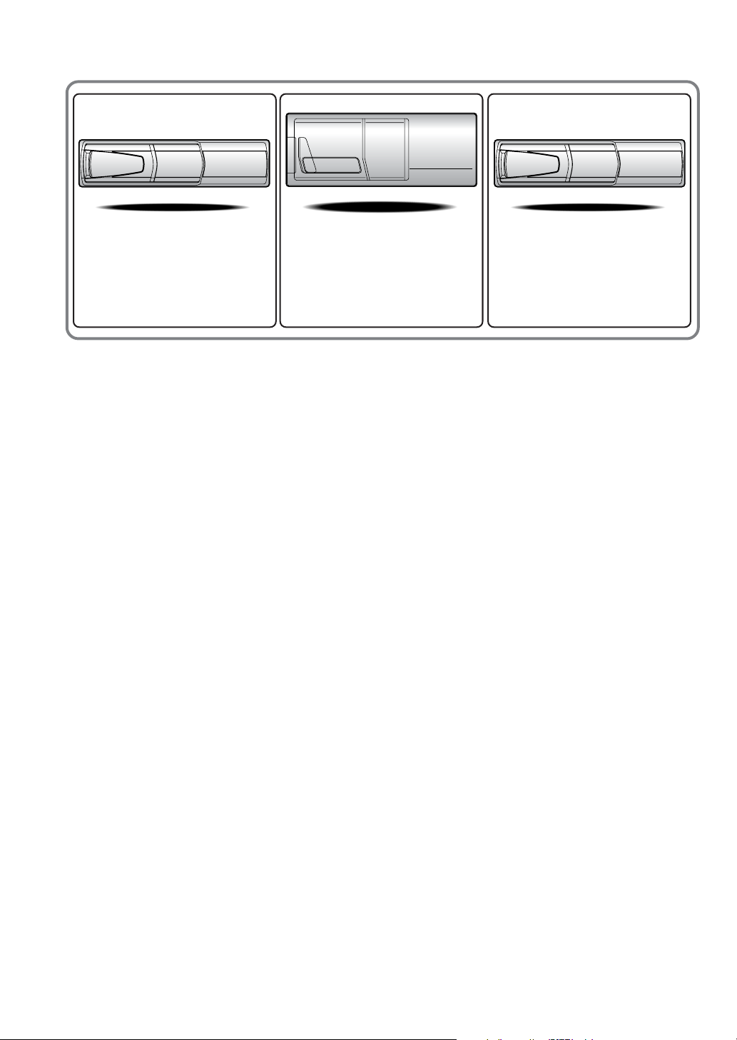
• CD changer for IVA-D901.
•
Changeur CD pour
• Cambiador de CD para IVA-D901.
IVA-D901
.
CHA-1214
• CD changer for IVA-D901.
•
Changeur CD pour
• Cambiador de CD para IVA-D901.
IVA-D901
.
Alpine CD Changers Give You More!
More musical selections, more versatility, more convenience.
The CHA-S634 is a high-performance 6-disc changer with a new M DAC, CD-R/RW PLAY BACK, MP3
PLAY BACK and CD TEXT. The CHA-1214 Ai-NET model holds 12 discs, and the CHM-S630 M-Bus
model is a super-compact 6-disc changer with a CD-R/RW PLAY BACK.
Changeurs de CD Alpine : vous avez le choix!
Plus de sélections musicales, plus de souplesse, plus de confort.
Le modèle CHA-S634 est un changeur 6 disques ultra performant équipé des nouvelles fonctions M DAC,
CD-R/RW PLAY BACK, MP3 PLAY BACK et CD TEXT. Le modèle CHA-1214 Ai-NET contient 12
disques. Le modèle CHM-S630 M-Bus est un changeur 6 disques super compact doté de la fonction CD-R/
RW PLAY BACK.
¡Los cambiadores Alpine de CD le ofrecen más!
Más selecciones musicales, más versatilidad y más ventajas.
CHA-S634 es un cambiador de seis discos de alto rendimiento con nuevo M DAC, CD-R/RW PLAY BACK,
MP3 PLAY BACK y CD TEXT. El modelo CHA-1214 Ai-NET alberga 12 discos y el modelo CHM-S630
M-Bus es un cambiador de seis discos de tamaño reducido con un CD-R/RW PLAY BACK.
Page 3

ENGLISH
Contents
Operating Instructions
WARNING
WARNING .................................................. 4
CAUTION ................................................... 4
PRECAUTIONS ......................................... 5
Discs playable on this unit ...................... 6
Getting Started
Basic Operation................................................. 8
Turning Power On or Off .................................. 9
Detaching and Attaching the Front Panel ......... 9
Initial System Start-Up ..................................... 9
Raising/Lowering the Monitor.......................... 9
Selecting the Monitor Opening Angle ............ 10
Adjusting the Monitor Viewing Angle ............ 10
Moving the Monitor to be Flat ........................ 10
Adjusting the Volume/Balance (Between
Left and Right)/Fader (Between Front
and Rear)/Defeat ....................................... 10
Lowering Volume Quickly .............................. 10
Radio
Listening to the Radio ..................................... 11
Manual Storing of Station Presets .................. 11
Automatic Memory of Station Presets ............ 11
Tuning to Preset Stations ................................ 11
CD/MP3
Playback .......................................................... 12
Repeat Play ..................................................... 12
M.I.X. (Random Play) .................................... 13
Selecting Folders (concerning MP3) .............. 13
About MP3 ...................................................... 13
DVD/Video CD
Playing DVD/Video CD ................................. 14
To display the DVD mode screen ................ 15
If a menu screen appears .............................. 16
Stopping Playback (PRE STOP)..................... 16
Stopping Playback .......................................... 16
Fast-forwarding/Fast-reversing ....................... 17
Finding the Beginnings of Chapters or Tracks ...
Playing Still Frames (Pausing) ....................... 17
Frame-by-frame Playback............................... 17
Slow Motion Playback .................................... 17
Chapter/Track/Title Repeat Playback ............. 17
Searching by Title Number (DVD only) ......... 18
Searching Directly by Chapter or
Track Number ........................................... 18
Switching the Angle (DVD only) ................... 18
Switching the Audio Tracks ............................ 18
Switching the Subtitles (Subtitle Language)
(DVD only) .............................................. 19
Switching from the disc menu ..................... 19
Displaying the Disc Status for DVD............... 19
Displaying the Disc Status for Video CD ....... 19
Sound Setting
Setting the MX mode ...................................... 20
Setting the Bass Engine .................................. 21
Setting the Bass Control ............................... 21
Setting the Treble Control ............................ 21
About the Time Correction .......................... 22
Bass Focus.................................................... 22
Time Correction ........................................... 23
Adjusting the Built-in Crossover ................. 23
Subwoofer On and Off .................................... 23
Other Useful Features
Titling Radio Stations/Discs ........................... 24
Displaying the Title List ................................. 24
Setting of Scrolling ......................................... 25
Rear Entertainment Function .......................... 25
Switching the function of the remote sensor ...
Blackout Mode On and Off............................. 26
Demonstration ................................................. 26
Switching Display Modes ............................... 26
Displaying the Spectrum Analyzer ................. 27
Switching the Visual Source Only
(Simul Function) ....................................... 27
17
25
1-EN
Page 4

Setup
DVD Setup
DVD Setup Operation ..................................... 28
Changing the language setting ........................ 28
Setting of the Menu Language ........................ 28
Setting of the Audio Language ....................... 28
Setting of the Subtitle Language ..................... 29
Changing the Country Code Setting ............... 29
Setting the Rating Level (Parental Lock)........ 29
Changing the Digital Output Setting .............. 30
Setting the Digital Output ............................... 31
Setting the TV Screen Setting ......................... 31
GENERAL Setup
General Setup Operation ................................. 31
Setting Automatic Opening/Closing of the
Monitor ...................................................... 32
Setting Visual Mode ........................................ 32
Playing MP3 Data ........................................... 32
Sound (Beep) Guide Function ........................ 32
Displaying the Time........................................ 32
Setting the Time .............................................. 32
Setting Daylight Saving Time ......................... 32
Switching the Incoming Calls of the
Telephone .................................................. 32
SYSTEM Setup
System Setup Operation.................................. 33
Navigation Interruption and Adjusting its
Volume ...................................................... 33
Setting the Navigation Mode .......................... 33
Setting the AUX Mode .................................... 33
Name External Equipment to be Displayed .... 34
Setting of the Rear Camera ............................. 34
Setting of the External Monitor Output .......... 34
Setting the External Device Interrupt Mode ... 34
Setting the Interrupt Icon Display ................... 34
Optical Digital Input Selection for an External
Audio Processor ........................................ 34
DISPLAY Setup
Display Setup Operation ................................. 35
Illumination Control ....................................... 35
Adjusting Brightness....................................... 35
Adjusting Tint of Picture ................................ 35
Adjusting Color of Picture .............................. 35
Switching Background Textures ..................... 35
Setting Automatic Background Textures ........ 35
Navigation System (Optional)
Controlling the Navigation System (Optional) ... 36
Auxiliary Device (Optional)
Operating Auxiliary Devices (Optional) ......... 36
Changer (Optional)
Controlling CD Changer (Optional) ............... 37
Multi-Changer Selection (Optional) ............... 38
XM Radio (Optional)
Receiving XM Channels with the XM Receiver
(Optional) .................................................. 38
Tuning in to Categorized Programs ................ 39
Changing the Display...................................... 39
Checking the XM Radio ID Number .............. 39
Storing XM Channel Presets........................... 39
Receiving Stored XM Channels...................... 39
Displaying the Category/Channel Name
Title List ............................................................
MobileHub™ Link (Optional)
About MobileHub™ Link (Optional) ............. 40
Telephone Reception ....................................... 41
Calling
Calling by using the Speed Dial ................... 41
Dial call ........................................................ 41
Calling by the address book ......................... 42
Calling by the outgoing / incoming / absent
incoming history........................................ 42
SMS (Short Message Service) Operation
Receiving a Short Message .......................... 42
Sending a standardized sentence .................. 43
40
2-EN
Page 5

External Audio Processor (Optional)
Adjustment Procedure for Dolby Surround .... 44
Setting the Speakers ........................................ 45
Set MX Mode of the External Audio Processor ....
X-OVER Adjustment ...................................... 46
Performing Time Correction Manually (TCR)/
Swithing the Phase .................................... 46
Graphic Equalizer Adjustments ...................... 47
Parametric Equalizer Adjustments .................. 47
BASS COMP. Setting ..................................... 48
Bass Focus ...................................................... 48
Speaker Setup ................................................. 48
Setting of Dolby 5.1ch .................................... 49
Adjusting the acoustic image ....................... 49
Mixing bass sound to the rear channel ......... 49
Achieving powerful high volume sound ...... 49
Adjusting the speaker levels......................... 50
Adjusting the DVD Level ............................... 50
Storing Settings in the Memory ...................... 50
Getting out the Preset Memory ....................... 50
Using the ProLogic II Mode ........................... 51
Linear PCM Setting ........................................ 51
Installation and Connections
45
WARNING
WARNING ................................................67
CAUTION ................................................. 67
PRECAUTIONS ....................................... 67
Installation ...................................................... 68
Connections (IVA-D901 Wiring Diagram) ..... 71
System Example ............................................. 73
LIMITED WARRANTY
Remote Control
Operating for the IVA-D901 ........................... 52
Operating the DVD player/DVD changer
(sold separately) ........................................ 54
Operating the Navigation (sold separately) .... 55
Operating a separately sold TV monitor ...... 55
Battery Replacement ....................................... 56
Notes on Using the Remote Control ............... 56
Information
About DVDs ................................................... 57
Terminology .................................................... 58
List of Language Codes .................................. 59
List of Country Codes ..................................... 60
In Case of Difficulty ....................................... 62
Specifications .................................................. 66
3-EN
Page 6
Operating Instructions
USE THE CORRECT AMPERE RATING WHEN REPLACING
WARNING
FUSES.
Failure to do so may result in fire or electric shock.
WARNING
This symbol means important instructions.
Failure to heed them can result in serious
injury or death.
INSTALL THE PRODUCT CORRECTLY SO THAT THE
DRIVER CANNOT WATCH TV/VIDEO UNLESS THE VEHICLE
IS STOPPED AND THE EMERGENCY BRAKE IS APPLIED.
It is dangerous (and illegal in many states) for the driver to watch
TV/Video while driving a vehicle. Installing this product
incorrectly enables the driver to watch TV/Video while driving.
This may cause a distraction, preventing the driver from looking
ahead, thus causing an accident. The driver or other people could
be severely injured.
DO NOT WATCH VIDEO WHILE DRIVING.
Watching the video may distract the driver from looking ahead of
the vehicle and cause an accident.
DO NOT OPERATE ANY FUNCTION THAT TAKES YOUR
ATTENTION AWAY FROM SAFELY DRIVING YOUR
VEHICLE.
Any function that requires your prolonged attention should only
be performed after coming to a complete stop. Always stop the
vehicle in a safe location before performing these functions.
Failure to do so may result in an accident.
KEEP THE VOLUME AT A LEVEL WHERE YOU CAN STILL
HEAR OUTSIDE NOISE WHILE DRIVING.
Failure to do so may result in an accident.
MINIMIZE DISPLAY VIEWING WHILE DRIVING.
Viewing the display may distract the driver from looking ahead of
the vehicle and cause an accident.
DO NOT BLOCK VENTS OR RADIATOR PANELS.
Doing so may cause heat to build up inside and may result in fire.
USE THIS PRODUCT FOR MOBILE 12V APPLICATIONS.
Use for other than its designed application may result in fire,
electric shock or other injury.
DO NOT PLACE HANDS, FINGERS OR FOREIGN OBJECTS
IN INSERTION SLOTS OR GAPS.
Doing so may result in personal injury or damage to the product.
CAUTION
This symbol means important instructions.
Failure to heed them can result in injury or
material property damage.
HALT USE IMMEDIATELY IF A PROBLEM APPEARS.
Failure to do so may cause personal injury or damage to the
product. Return it to your authorized Alpine dealer or the nearest
Alpine Service Center for repairing.
DO NOT MIX NEW BATTERIES WITH OLD BATTERIES.
INSERT WITH THE CORRECT BATTERY POLARITY.
When inserting the batteries, be sure to observe proper polarity (+
and –) as instructed. Rupture or chemical leakage from the
battery may cause fire or personal injury.
KEEP FINGERS AWAY WHILE THE MOTORIZED FRONT
PANEL OR MOVING MONITOR IS IN MOTION.
Failure to do so may result in personal injury or damage to the
product.
DO NOT DISASSEMBLE OR ALTER.
Doing so may result in an accident, fire or electric shock.
USE ONLY IN CARS WITH A 12 VOLT NEGATIVE GROUND.
(Check with your dealer if you are not sure.) Failure to do so may
result in fire, etc.
KEEP SMALL OBJECTS SUCH AS BATTERIES OUT OF THE
REACH OF CHILDREN.
Swallowing them may result in serious injury. If swallowed,
consult a physician immediately.
4-EN
Page 7
PRECAUTIONS
Product Cleaning
Use a soft dry cloth for periodic cleaning of the product. For
more severe stains, please dampen the cloth with water only.
Anything else has the chance of dissolving the paint or damaging
the plastic.
Temperature
Be sure the temperature inside the vehicle is between +45°C
(+113°F) and 0°C (+32°F) before turning your unit on.
Moisture Condensation
You may notice the disc playback sound wavering due to
condensation. If this happens, remove the disc from the player
and wait about an hour for the moisture to evaporate.
Damaged Disc
Do not attempt to play cracked, warped, or damaged discs.
Playing a bad disc could severely damage the playback
mechanism.
Maintenance
If you have problems, do not attempt to repair the unit yourself.
Return it to your Alpine dealer or the nearest Alpine Service
Station for servicing.
Never Attempt the Following
Do not grip or pull out the disc while it is being pulled back into
the player by the automatic reloading mechanism.
Do not attempt to insert a disc into the unit when the unit power
is off.
Irregular Shaped Discs
Be sure to use round shaped discs only for this unit and never use
any special shaped discs.
Use of special shaped discs may cause damage to the mechanism.
Installation Location
Make sure the IVA-D901 will not be installed in a location
subjected to:
•Direct sun and heat
•High humidity and water
•Excessive dust
•Excessive vibrations
Correct Handling
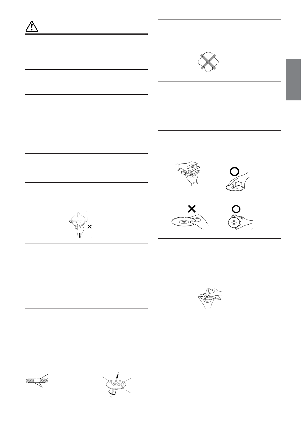
Do not drop the disc while handling. Hold the disc so you will
not leave fingerprints on the surface. Do not affix tape, paper, or
gummed labels to the disc. Do not write on the disc.
CORRECT
INCORRECT CORRECT
Inserting Discs
Your player accepts only one disc at a time for playback. Do not
attempt to load more than one disc.
Make sure the label side is facing up when you insert the disc.
Your player will automatically eject any disc that is inserted
incorrectly. If the player continues to eject a correctly inserted
disc, push the RESET switch with a pointed object such as a
ballpoint pen.
Playing a disc while driving on a very bumpy road may result in
skips, but this will not scratch the disc or damage the player.
New Discs
As a protective measure to prevent the disc from jamming, the
DVD player will automatically eject discs with irregular surfaces
or inserted incorrectly. When a new disc is inserted into the
player and ejected after initial loading, using your finger, feel
around the inside of the center hole and outside edge of the disc.
If you feel any small bumps or irregularities, this could inhibit
proper loading of the disc. To remove the bumps, rub the inside
edge of the hole and outside edge of the disc with a ball-point pen
or other such instrument, then insert the disc again.
New
Disc
Outside
(Bumps)
Bumps
Center Hole
Center Hole
Disc Cleaning
Fingerprints, dust, or soil on the surface of the disc could cause
the DVD player to skip. For routine cleaning, wipe the playing
surface with a clean, soft cloth from the center of the disc to the
outer edge. If the surface is heavily soiled, dampen a clean, soft
cloth in a solution of mild neutral detergent before cleaning the
disc.
Continued
5-EN
Page 8
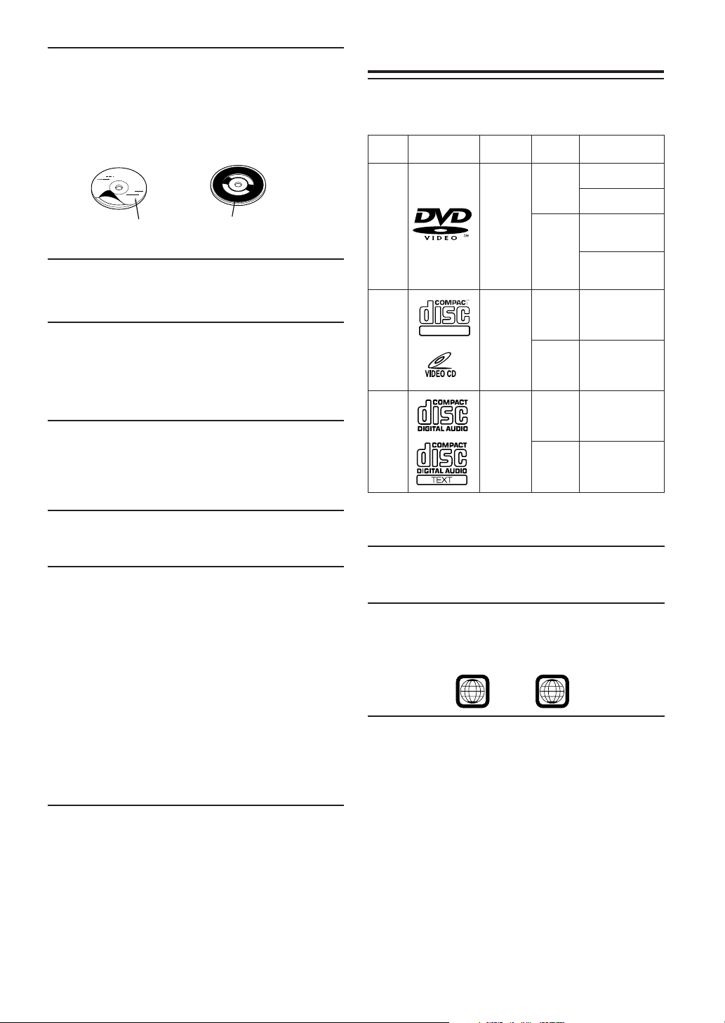
Disc Accessories
There are various accessories available on the market for
protecting the disc surface and improving sound quality.
However, most of them will influence the thickness and/or
diameter of the disc. Using such accessories can cause
operational problems. We recommend not using these accessories
on discs played in Alpine DVD players.
Disc StabilizerTransparent Sheet
Handling the Detachable Front Panel
• Do not expose to rain or water.
• Do not drop or subject to shock.
• After turning the system off, a slight ghost of the image will
remain temporarily. This is an effect peculiar to LCD
technology and is normal.
• In cold temperature conditions, the screen may lose contrast
temporarily. After a short warm-up period, it will return to
normal.
Alpine products equipped with the Ai-NET bus, connected to the
IVA-D901, can be operated from the IVA-D901. Depending on
the products connected, the functions and displays will vary. For
details, consult your Alpine dealer.
Discs playable on this unit
Playable Discs
The discs listed below can be played on this unit.
Max.
playing time
One-sided disc
Approx. 4 hours
Two-sided disc
Approx. 8 hours
One-sided disc
Approx.
80 Minutes
Two-sided disc
Approx.
160 Minutes
Approx.
74 Minutes
Approx.
20 Minutes
Approx.
74 Minutes
Approx.
20 Minutes
DVD
Video
Video
CD
Music
CD
Mark
(logo)
DIGITAL VIDEO
Recorded
content
Audio
+
Video
(Moving
pictures)
Audio
+
Video
(Moving
pictures)
Audio
Disc
size
12 cm*
8 cm
12 cm
8 cm
12 cm
8 cm
(CD
single)
Remove the anti-theft cover when you drive. This prevents the
cover from falling off the unit and interfering with the safe
operation of the vehicle.
Operation of some of the functions of this unit is very complex.
Because of this, it was deemed necessary to place these functions
into a special screen. This will restrict operation of these
functions to times when the vehicle is parked. This ensures the
focus of the driver's attention will be on the road and not on the
IVA-D901. This has been done for the safety of the driver and
passengers.
Title Input and Audio Processor Adjustments cannot be made if
the car is moving. The car must be parked and the parking brake
must be engaged for the procedure described in the Owner's
Manual to be valid. The warning "CAN'T OPERATE WHILE
DRIVING," will be displayed if any attempts are made to
perform these operations while driving.
This operation is the same as when selecting sources using the
remote control. When the car is parked, the selection is made as
described in the Owner's Manual.
* Two-layer DVD disc compatible
Discs that cannot be played
DVD-ROMs, DVD-RAMs, DVD+Rs, DVD + RWs, CD-ROMs
(excluding MP3 files), photo CDs, etc.
DVD region number (playable region number)
This DVD head unit will play back any disc whose region
number is 1 (or All). DVDs with a region number other than
those listed below, cannot be played on this DVD player.
1
ALL
Video CDs
This DVD head unit is compatible with playback control (PBC)
compatible video CDs (version 2.0).
“PBC” is a function by which you can use menu screens recorded
on the disc to find the scene you want to watch and view various
types of information in dialog style.
6-EN
Page 9

Using compact discs (CD/CD-R/CD-RW)
If you use unspecified compact discs, correct performance cannot
be guaranteed.
You can play CD-Rs (CD-Recordable)/CD-RWs (CD-ReWritable)
which have been recorded only on audio devices. You can also
play CD-Rs/CD-RWs containing MP3 formatted audio files.
•Some of the following Discs may not play on this unit:
Flawed Discs, Discs with fingerprints, Discs exposed to
extreme temperatures or sunlight (e.g., left in the car or this
unit), Discs recorded under unstable conditions, Discs on
which a recording failed or a re-recording was attempted,
copy-protected CDs which do not conform to the audio CD
industry standard.
•Use discs with MP3 files written in the format compliant with
ISO 9660 level 1 or level 2. For details, see pages 13 and 14.
To customers using CD-R/CD-RW
• If a CD-R/CD-RW cannot be played back, make sure the last
recording session was closed (finalized).
•Finalize the CD-R/CD-RW if necessary, and attempt playback
again.
Tips for making your own CDs
The IVA-D901 plays DVD Video, Video CD, Audio CD and has a
built in MP3 decoder.
The following information is designed to help you create your
own music CDs (either Audio CD or MP3 encoded CD-R/RW
files).
What is the difference between an Audio and MP3 CD?
An Audio CD is the same format as the commercial CDs you buy
in the store (also known as CD-DA). MP3 (MPEG Audio Layer
3) is a data file that uses a compression scheme to reduce the size
of the music file.*
Hybrid Audio CD and Data (MP3) CD-R/RW discs:
The IVA-D901 can read either sector on the disc. Choose
MixDisc CD to play the CD audio section or MixDisc MP3 to
play the MP3 section.*
Multisession CD-R/RW:
Once a recording has been stopped, this is considered one
session. If the disc is not closed (finalized), additional data may
be added. Once this additional data has been recorded, this
becomes a “multisession” CD. The IVA-D901 can only read
multisession DATA Formatted discs (MP3 files - Not Audio CD
files).
MP3 ID3 Tag Information:
The IVA-D901 read and displays MP3 ID3v1 tag information.
MP3 files created with ID3v2 tag information can be played back
but the tag info cannot be read or displayed.
Properly formatted MP3 Discs:
Use ISO-9660 formatting to insure proper playback. You may use
standard ISO naming Level 1 (8.3 DOS standard), Level 2 (32
characters) or Joliet, (Windows or Macintosh long filenames) file
naming conventions.*
*Please consult the Owner’s manual for additional information.
On handling Compact Discs (CD/CD-R/CD-RW)
•Do not touch the surface.
•Do not expose the disc to direct sunlight.
•Do not affix stickers or labels and do not write on the
surface.
•Clean the disc when it is dusty.
•Make sure that there are no bumps around the disc.
•Do not use commercially available disc accessories.
Do not leave the disc in the car or the unit for a long time.
Never expose the disc to direct sunlight.
Heat and humidity may damage the disc and you may not be able
to play it again.
Using DVD-Rs/DVD-RWs
•This unit is compatible only with discs recorded in the DVDVideo mode.
Discs recorded in the DVD-VR mode cannot be played back.
•Note that discs not finalized (processed to enable to play on
playback-only DVD players) cannot be played on this DVD
player.
•Some discs may not play back, depending on the recording
device. (This unit has a copy protection function. Discs copied
illegally will not be played back. Some files recorded by a
software using an improper recording system may be
recognized as illegally copied.)
• In the following cases, the disc may not play on this unit:
discs recorded by certain DVD recorders, certain irregular
discs, flawed discs, dirty discs, when the pickup lens of this
DVD player is dirty, or when moisture condensation has
occurred inside the unit.
•Be sure to follow all cautions included with your DVD-Rs/
DVD-RWs discs.
•Do not put stickers, seals, or tape on the label side of DVD-Rs/
DVD-RWs.
•Compared to the regular discs, DVD-Rs/DVD-RWs are more
affected by heat, moisture, and direct sunlight. If left in a car,
etc., damage may occur and it might not play on this unit.
Disc terminology
Title
If titles are programmed for the DVD, these are the largest units
of division of the information recorded on the disc.
Chapter
Each Title may also be divided into smaller divisions called
Chapters. These can be specific scenes or musical selections.
* This product incorporates copyright protection technology that is
protected by method claims of certain U.S. patents and other
intellectual property rights owned by Macrovision Corporation and
other rights owners. Use of this copyright protection technology
must be authorized by Macrovision Corporation, and is intended
for home and other limited viewing uses only unless otherwise
authorized by Macrovision Corporation. Reverse engineering or
disassembly is prohibited.
* Manufactured under license from Dolby Laboratories. “Dolby,”
“Pro Logic” and the double-D symbol are trademarks of Dolby
Laboratories. Confidential unpublished works. ©1992-1997
Dolby Laboratories. All rights reserved.
* “DTS” and “DTS2.0 + Digital Out” are trademarks of Digital
Theater Systems, inc.
7-EN
Page 10
Getting Started
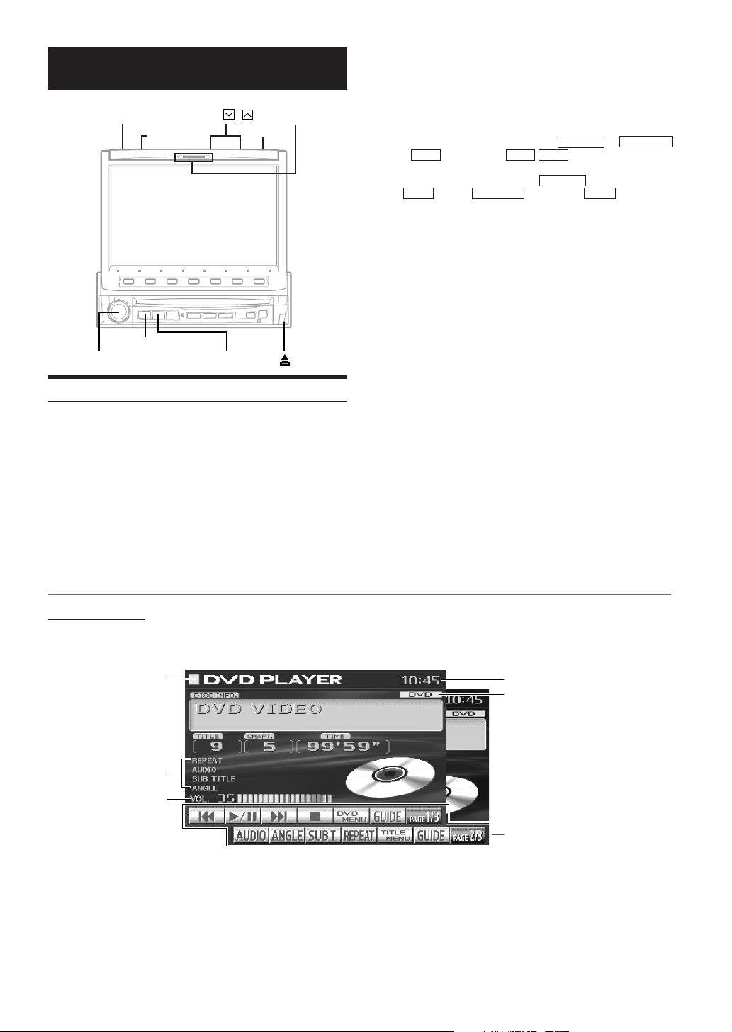
Action indicator
,
OPEN/CLOSE
FLAT/SLIDE
SOURCE/POWER
Rotary encoder
Basic Operation
This section describes the basic operation of the DVD. These
operations also apply to the other sources.
Press SOURCE/POWER on the unit to turn the
1
power on.
TILT
MUTE
WIDE/DISP.
Press SOURCE/POWER.
3
The display shows the main menu screen.
Turn the Rotary encoder and select "DVD
4
PLAYER" from the main menu.
• If an optional DVD player or DVD Changer is connected and
its power is on, the display shows " EXT.DVD or DVD CHG
, AUX2 " instead of " AUX1 AUX2 ."
• If both the optional DVD player and DVD Changer are
connected, the display shows " EXT.DVD " instead of "
AUX1 ", and " DVD CHG " instead of " AUX2 ".
Press the Rotary encoder to execute the
5
selection.
The DVD player mode screen is displayed.
(The DVD disc is played back.)
• If PAGE 1/2 or PAGE 1/3 appears in the Function Guide
menu, there are additional functions available for the selected
source. Access these functions by pressing 7.
Press SOURCE/POWER again to select another
6
source.
Tip
The action indicator always lights up except for the following cases.
• Blinks when the monitor opens or closes.
• Blinks when the answer phone has a message. (Only
when Mobile Hub (CXA-B200NK) is connected.)
• Does not light up when the Illumination Control (Dimmer)
is set to ON.
Press OPEN/CLOSE to open the monitor.
2
The unit beeps 3 times and raises the monitor. The
opening screen appears on the monitor.
DVD Mode Screen
Selected Source
*Working State indicator
Volume Level
*
Tip
1Press and hold WIDE/DISP. for more than 2 seconds.
The working indicator display in the mode main screen is
switched to the spectrum analyzer display.
2Press and hold again WIDE/DISP. for more than 2 seconds to
return to the working indicator display.
Current Time
Shows the audio disc or video
disc currently playing
(During MP3 playback, shows the
sampling rate and the bit rate of
the MP3 file when it was made.)
The Function Guide displays the
labels for each of the Function
buttons. These labels will change
depending upon the functions for
the selected source.
8-EN
Page 11
Compatibility with Factory Steering Wheel Radio
Controls
If your vehicle has steering wheel controls for the radio,
an optional steering wheel control interface may be
available to connect to your Alpine radio. For details,
contact your Alpine dealer.
Turning Power On or Off
Some of this unit's functions cannot be performed while the vehicle is
in motion. Be sure to stop your vehicle in a safe location and apply the
parking brake, before attempting these operations.
Press SOURCE/POWER to turn on the unit.
1
The opening screen appears automatically.
•
The unit can be turned on by pressing any button on the unit
except the FLAT/SLIDE, OPEN/CLOSE , TILT and
c (Eject).
Press and hold SOURCE/POWER for at least 2
2
seconds to turn off the unit.
• The IVA-D901 draws minimal current even when its power switch
is turned off. If the switched power (ignition) lead of the IVA-D901
is connected directly to the positive (+) post of the vehicle's battery,
the battery may be discharged. If this lead is unswitched, it must be
disconnected from the battery post should the vehicle be left unused
for an extended period of time.
An SPST (Single-Pole, Single-Throw) switch (sold separately) can
be added to simplify this procedure. Then, you can simply place it
in the OFF position when you leave the vehicle. Turn the SPST
switch back ON before using the IVA-D901. For connecting the
SPST switch, refer to the "Connection Diagram of SPST switch"
(page 70).
• Some operation of the unit cannot be performed while the vehicle is
in motion. In this case, be sure to first stop your vehicle and apply
the parking brake, then perform the operation.
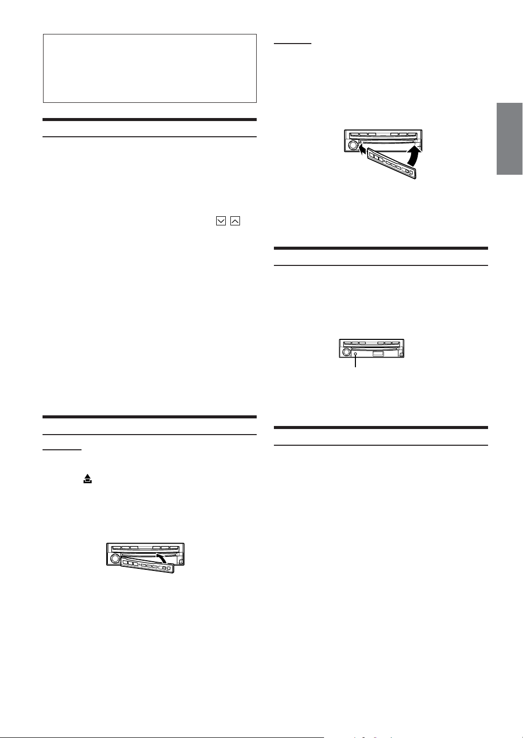
Detaching and Attaching the Front Panel
Detaching
Turn off the unit power.
1
Press (Release) at the lower right side until the
2
front panel pops out.
Grasp the right side of the front panel, lift it up
3
slightly then pull it out.
• The front panel may become hot in normal usage (especially the
connector terminals on the back of the front panel.) This is not a
malfunction.
•To protect the front panel, place it in the supplied carrying case.
Attaching
Insert the left side of the front panel into the main
1
unit. Align the groove on the front panel with the
projections on the main unit.
Push the right side of the front panel until it locks
2
firmly into the main unit.
1
• Before attaching the front panel, make sure that there is no dirt or
dust on the connector terminals and no foreign object between the
front panel and the main unit.
•Attach the front panel carefully, holding the sides of the front panel
to avoid pushing buttons by mistake.
2
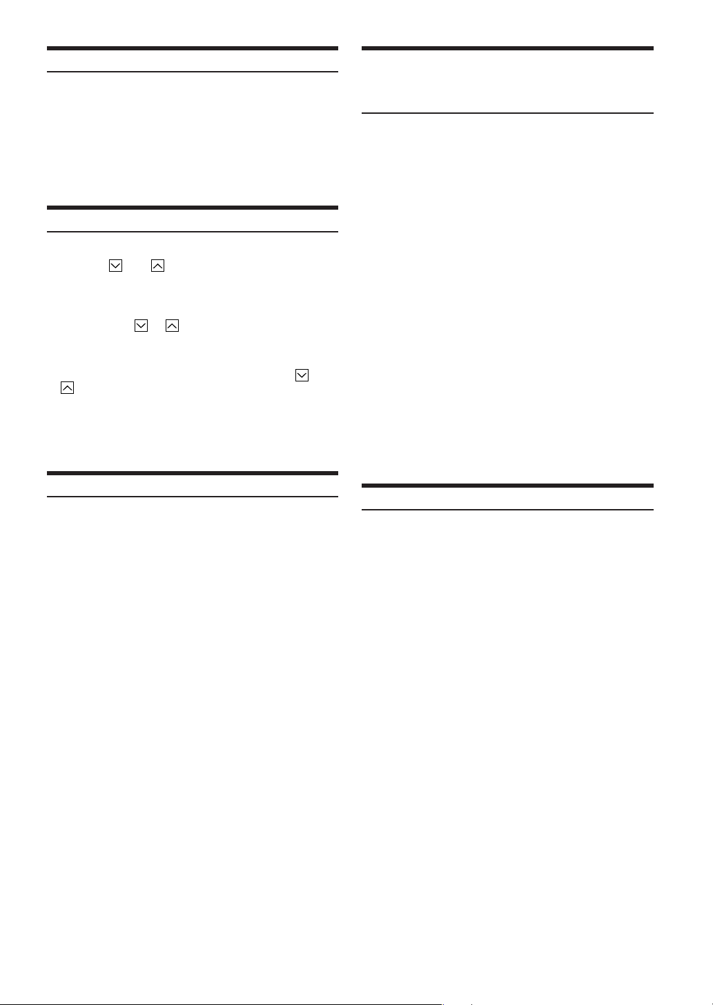
Initial System Start-Up
Immediately after installing or applying power to the unit, it should be
initialized. To do this, first, remove the detachable front panel. Behind
the front panel, to the left of the connector, there is a small hole.
Using a pencil or other pointed object, press the reset switch mounted
behind this hole to complete the initialization procedure.
RESET switch
• Any of the buttons does not function while the monitor is closing by
reset.
Raising/Lowering the Monitor
Press OPEN/CLOSE.
The unit beeps 3 times and raises (or lowers) the monitor
automatically.
• The IVA-D901 is a precision device. With gentle handling, its
unique capabilities can be enjoyed for a long time.
• If the monitor touches an obstacle while it is being raised (or
lowered), the unit will stop raising (or lowering) the monitor
immediately. Should this occur, remove the obstacle and press
OPEN/CLOSE again to lower the monitor.
• When the movable monitor is opened, do not place any object on
the monitor and be careful not to bump or apply any pressure to
the monitor while it is open. This can cause damage to the
mechanism.
•In low ambient temperature conditions, the display may be dark for
a short period of time immediately after the power is turned on.
Once the LCD has warmed up, the display returns to normal.
•For your safety, some operation of the unit cannot be performed
while the vehicle is in motion. In this case, first stop the vehicle
and engage the parking brake, then perform the operation.
• Operation of the remote control (pages 52-55) can be carried out
even while the monitor screen is closed.
9-EN
Page 12
Selecting the Monitor Opening Angle
The monitor opening angle can be set in 2 positions.
Press and hold FLAT/SLIDE for at least 2 seconds
while the monitor is being raised.
Each press changes the monitor angle back or forth.
• When the back-and-force adjustment of the monitor is interrupted
by something cutting in, the monitor functions only opening or
closing.
Adjusting the Monitor Viewing Angle
Adjust the monitor's angle for better visibility.
Press TILT and to adjust the monitor's angle so
the screen will be in the best viewing position.
Pressing the buttons produces a beep and changes the
screen angle between 40 and 105 degrees.
• By pressing TILT or and holding, the angle changes
continuously.
• If the monitor touches an obstacle while the angle is being adjusted
the unit stops the screen immediately.
Should this happen, remove the obstacle and press TILT or
again.
• The screen color will vary when viewed at certain angles. Adjust
the screen angle for the best viewing position.
• If the voltage of the vehicle's battery power is low, the screen may
blink when the screen angle is changed. This is normal and not a
malfunction.
Moving the Monitor to be Flat
When you want to operate some function on the car (air conditioner,
etc.) which is hidden by the raised monitor, use this function.
Press FLAT/SLIDE.
1
The monitor moves to the flat position.
Press FLAT/SLIDE again.
2
The monitor returns to the previous angle.
• The monitor returns to the previous angle from being flat after 10
seconds.
• If an excessive force is added to the monitor when the monitor is
flat, putting an object on the back of the monitor for example, it
may cause a malfunction.
Adjusting the Volume/Balance (Between Left
and Right)/Fader (Between Front and Rear)/
Defeat
Press the Rotary encoder repeatedly until the
1
mode you wish to adjust is obtained.
Each press changes the modes as follows:
VOL. → NAV.* → SUB W.* → BAL. → FAD. → DEFEAT →
VOL.
*NAV. (page 33) and SUBW. (page 23) cannot be adjusted
while they are set to OFF.
Volume: 0 - 35
Balance: L15 - R15
Fader: F15 - R15
Subwoofer: 0 - 15
NAV. MIX: 0 - 15
DEFEAT: ON/OFF
The volume level can be adjusted at any time by just
turning the Rotary encoder.
Turn the Rotary encoder to set to the desired
2
sound within 5 seconds after selecting the mode.
By setting Defeat ON, previously adjusted settings of
BASS and TREBLE will return to the factory defaults, but
MX will be turned off.
• If the Rotary encoder is not turned or pressed within 5 seconds
after selecting the Balance, Fader, Defeat and Subwoofer mode, the
unit automatically defaults back to the Volume mode.
Lowering Volume Quickly
Activating this function will instantly lower the volume level by 20
dB.
Press MUTE to activate the MUTE mode.
The audio level decreases by about 20 dB.
Pressing MUTE again brings the audio back to its previous
level.
10-EN
Page 13
Radio
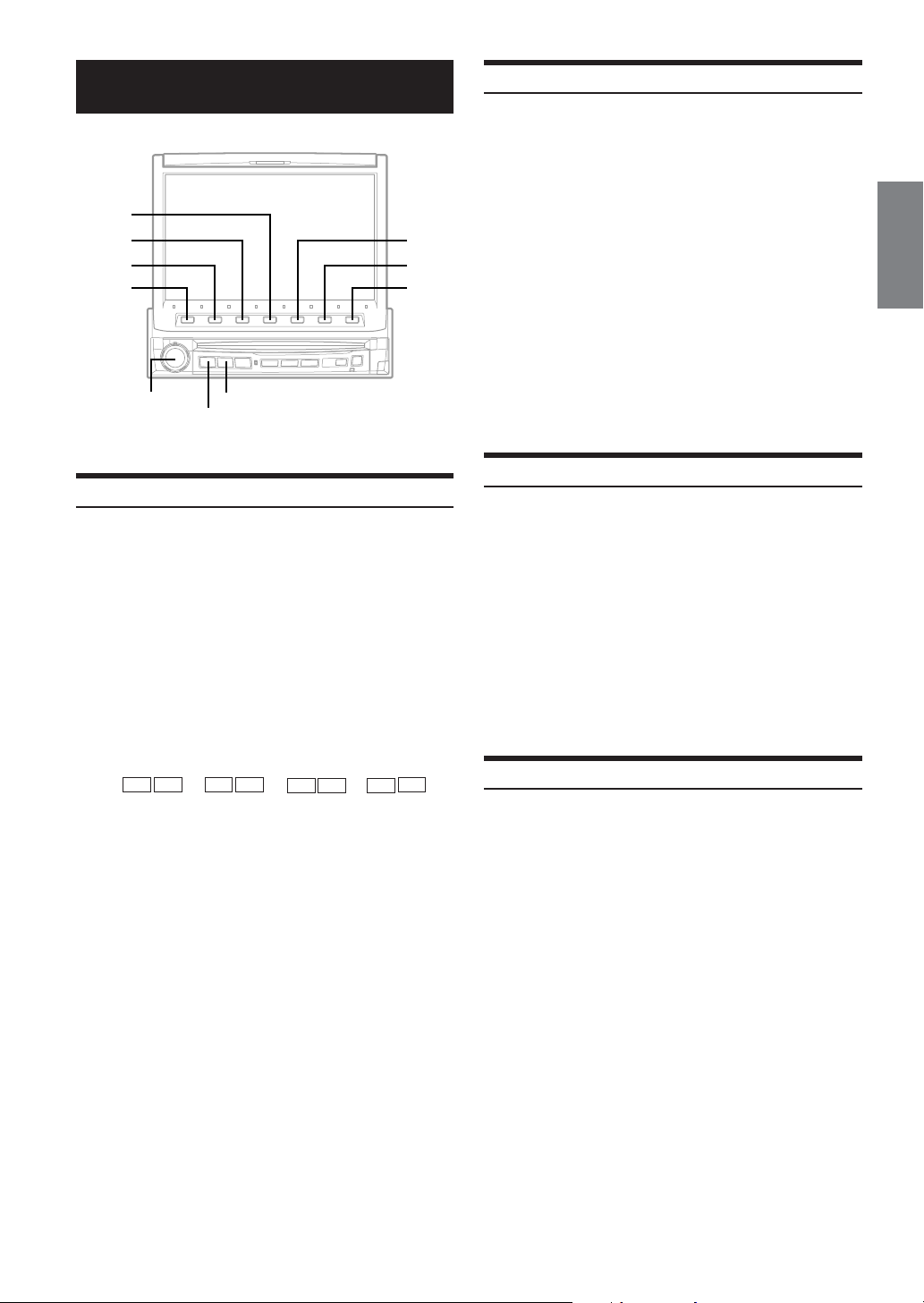
4
3
2
1
Rotary encoder
SOURCE/POWER
Listening to the Radio
Press SOURCE/POWER.
1
The main menu screen appears.
Turn the Rotary encoder to select "RADIO," then
2
press the Rotary encoder.
The radio mode is activated and the display changes to
the Radio Mode screen.
Press BAND to select the desired radio band.
3
Each press changes the bands as follows:
FM1 → FM2 → AM → FM1
Press 2 (TUNE) to choose the tuning mode.
4
Each press changes the function modes for the buttons
1 and 3 as follows:
Distance → Local → Manual → Distance
gg
• There are two modes you can select for auto tuning, DX and
Press 1 (() or 3 ()) to change the radio
5
frequency downward or upward respectively.
When the button is pressed and held, the frequency
changes continuously until the button is released.
• When a stereo FM station is tuned in, the STEREO indicator
appears in the display.
ff
g
f
gg
ff
Local:
- DX (Distance) mode (with DX SEEK indicator ON);
Both strong and weak stations will be tuned in.
- Local mode (with SEEK indicator ON);
Only strong stations will be tuned in.
The initial setting is DX.
BAND
g g
g
g g
f (f (
f (
f (f (
))
)
))
gg
g
gg
ff
f
ff
Manual Storing of Station Presets
Tune in a desired radio station you wish to store in
1
the preset memory by manual or automatic seek
tuning.
Press 7 (PAGE 1/2).
2
Press and hold any one of the Function buttons 1
3
5
6
7
(P. SET1) through 6 (P. SET6) for at least 2
seconds.
The selected station is stored.
Repeat the procedure to store up to 5 other
4
stations onto the same band.
To use this procedure for other bands, simply select the
band desired and repeat the procedure.
A total of 18 stations can be stored in the preset memory
(6 stations for each band; FM1, FM2, AM).
• If a preset memory has already been set in the same Function
button, it will be cleared and the new station will be memorized.
Automatic Memory of Station Presets
The tuner can automatically seek and store 6 strong stations in the
selected band in order of signal strength.
Press BAND in the radio mode to select the
1
desired radio band.
Press 6 (A.MEMO).
2
The tuner automatically seeks and stores 6 strong stations
into 1 (P. SET1) to 6 (P.SET6) in order of signal strength.
When the automatic storing has been completed, the
tuner goes to the station stored in 1 (P. SET1).
• If no stations are stored, the tuner will return to the original station
you were listening to before the automatic storing procedure
began.
Tuning to Preset Stations
You can tune in the preset stations in memory on each band using the
Function buttons.
Press BAND in the radio mode to choose the
1
desired radio band.
Press 1 (P. SET1) through 6 (P. SET6) that has
2
your desired preset station in memory.
The preset station is received.
11-EN
Page 14
CD/MP3
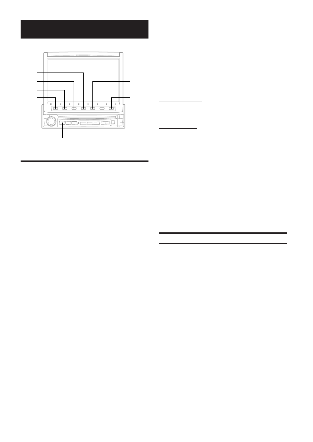
4
3
2
1
SOURCE/POWER
Playback
Press SOURCE/POWER to display the main menu
1
screen.
Turn the Rotary encoder and select the DVD
2
player mode. Then, press the Rotary encoder to
execute the selection.
The display shows the DVD player mode screen.
When a CD/MP3 is inserted into the DISC SLOT of the
IVA-D901, with the label side facing up, the unit starts to
play the CD/MP3.
- During CD play:
On the upper line of the DISC INFO (Disc Information),
the Track TEXT* is displayed.
On the lower line, the input title is displayed. When no
title is input, the DISC TEXT* is displayed.
* When a CD TEXT is inserted.
- During MP3 play:
On the upper line of the DISC INFO (Disc Information),
the file name is displayed at first, then the track name is
displayed if ID3TAG information is contained.
On the lower line, the folder name is displayed at first,
then the artist name and the album name is displayed if
ID3TAG information is contained.
- When an optional Alpine CD player is connected,
inserting a CD into the optional CD player starts
playback automatically.
- When an optional Alpine MD player is connected to the
IVA-D901, you can control the player from the IVA-D901.
(When the MDA-5051 is connected, MDs can be played
back only.)
cRotary encoder
Press 1 ( g) or 3 ( f) to select the desired
3
track (file).
Returning to the beginning of the current track (file):
Press 1 ( g).
Fast backward :
Press and hold 1 ( g).
Advancing to the beginning of the next track (file) :
Press 3 ( f).
5
7
Fast forward :
Press and hold 3 ( f).
To pause playback
Press 2 ( -/J).
Pressing 2 ( -/J) again will resume playback.
To e ject the disc
Press c.
If you use an optional CD player, press the eject button on the
optional CD player.
• The IVA-D901 models include a built-in MP3 unit. You can play
CD-ROMs, CD-Rs, and CD-RWs containing MP3 files on this unit.
Use the format compliant with ISO 9660 level 1 or level 2.
Fo r further information about playing or storing MP3 files, refer to
pages 13 and 14 before using the unit.
• The unit can play discs containing both audio data and MP3 data.
• The MP3 indicator is lit during MP3 playback.
• The track display for CD audio data playback is the track numbers
recorded on the disc.
• Three-inch (8cm) CD's can be used.
• "Playing MP3 Data" is mentioned on page 32 "GENERAL Setup".
• When an MP3 disc is played, it sometimes takes a few moment
until it starts.
Repeat Play
Press 4 (REPEAT) to play back repeatedly the track
being played.
The track (file) will be played repeatedly.
Press 4 (REPEAT) again and select OFF to deactivate the
repeat play.
*
CD: REPEAT →
MP3: REPEAT →
→ (off) → REPEAT
*
1
If a CD Changer or an MP3 compatible CD changer is connected
and the REPEAT ALL mode is selected, the unit repeatedly plays
back all tracks (files) on the disc selected.
*
2
Only files in a folder are repeatedly played back.
1
REPEAT ALL → (off) → REPEAT
*
2
REPEAT FOLDER →
*
1
REPEAT ALL
12-EN
Page 15

M.I.X. (Random Play)
About MP3
Press 5 (M.I.X.) in the play or pause mode.
The tracks (files) on the disc will be played back in a random
sequence.
To cancel M.I.X. play, press 5 (M.I.X.) again.
*
CD: M.I.X. →
*
MP3:
*
1
If a CD Changer equipped with the M.I.X. ALL function is
connected, M.I.X. ALL will also be selectable.
In this mode, the tracks on all the CDs in the current magazine will
be included in the random playback sequence.
*
2
If an MP3 compatible CD changer is connected, all files in a disc
are played back in random sequence, and playback shifts to the
next disc.
•To select the M.I.X. FOLDER mode:
(Only files in a folder are played back in random sequence. )
Press 5 (M.I.X.) after REPEAT FOLDER is selected.
The M.I.X. FOLDER mode is selected.
To cancel the M.I.X.FOLDER mode:
Press 4 (REPEAT) to cancel the REPEAT FOLDER.
The M.I.X. FOLDER mode is also canceled.
2
M.I.X. → (off) → M.I.X.
1
M.I.X. ALL → (off) → M.I.X.
Selecting Folders (concerning MP3)
During MP3 play, press 7 (PAGE 1/2).
1
The Function Guide display changes.
Press 1 (; F. DN) or 3 ( F. UP :) to select the
2
folder.
CAUTION
Except for personal enjoyment, duplicating audio data (including
MP3 data) or distributing, transferring, or copying it, whether for
free or for a fee, without the permission of the copyright holder is
strictly prohibited by the Copyright Act and by international treaty.
What is MP3?
MP3, whose official name is “MPEG-1 Audio Layer 3,” is a
compression standard prescribed by the ISO, the International
Standardization Organization and MPEG which is a joint
activity institution of the IEC.
MP3 files contain compressed audio data. MP3 encoding is
capable of compressing the audio data at extremely high
ratios shrinking music files by as much as one-tenth their
original size. This is achieved while still maintaining near CD
quality. The MP3 format realizes such high compression ratios
by eliminating the sounds that are either inaudible to the
human ear or masked by other sounds.
Method for creating MP3 files
The software used to create MP3 files is widely sold or free
from various sources. For details on creating MP3 files, refer to
the user's manual for that software.
The MP3 files that can be played back by this device have the
file extension “mp3.” Files with no extension can not be played
back.
Supported playback sampling rates and bit rates
Sampling rates: 32 kHz - 48 kHz, bit rates: 32 - 320 kbps
Note that for sampling rates such as 22.05 kHz, this device
may not display correctly.
ID3 tags
This device supports ID3 tag v1.
If ID3 tag data is in an MP3 file, this device can display the
title (track title), artist name, and album name ID3 tag data.
This device can only display single-byte alphanumeric
characters and the underscore.
Producing MP3 discs
MP3 files are prepared, then written to a CD-R or CD-RW
using CD-R writing software. A disc can hold a maximum of
255 files, and 255 folders.
Media supported
The media that this device can play back are CD-ROMs, CDRs, and CD-RWs.
Corresponding File Systems
This device supports discs formatted with ISO9660 Level 1 or
Level 2.
Under the ISO9660 standard,
there are some restrictions to remember.
The maximum nested folder depth is 8 (including the root
directory). File/folder names are limited to 31 characters
(except the extension).
Valid characters for folder/file names are letters A-Z (all
caps), numbers 0-9, and ‘_’ (underscore).
This device also can play back discs in Joliet, and other
standards that conform to ISO9660. However, sometimes the
file names, folder names, etc., are not displayed correctly.
Continued
13-EN
Page 16
Formats supported
This device supports CD-ROM XA, Mixed Mode CD,
Enhanced CD (CD-Extra) and Multi-Session.
This device cannot correctly play back discs recorded with
Track At Once or packet writing.
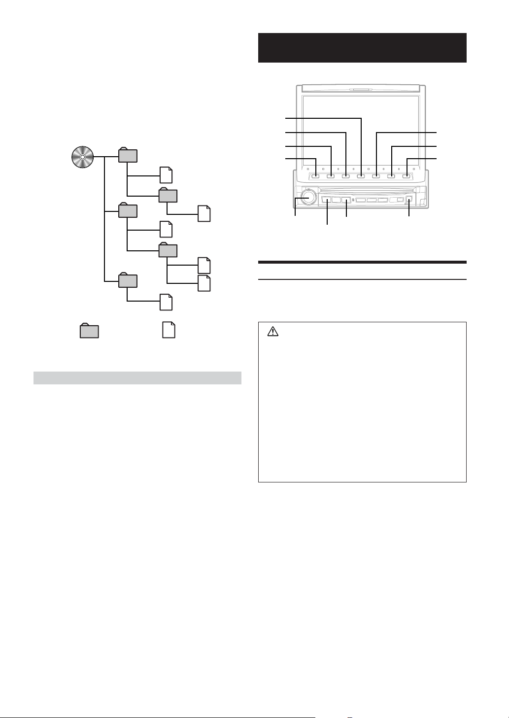
Order of tracks
The unit plays the files in the order that the writing software
writes them. Therefore, the playing order may not be the same
as the order you input. The playback order of the folders and
files is as follows. However, the folder and file playback order
differs from the folder no. and file no. indicated on the display.
1
1
2
3
3
4
5
6
2
4
5
DVD/Video CD
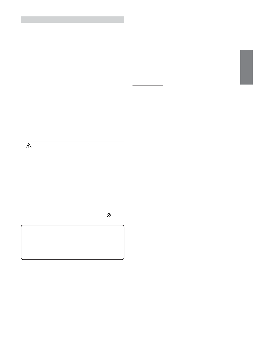
4
3
2
1
Rotary encoder
SOURCE/POWER
V.SEL
c
Playing DVD/Video CD
IVA-D901 has a built-in DVD player. When an optional Alpine DVD/
video CD/CD player (or DVD changer) is connected to the IVAD901, you can control it from the IVA-D901.
5
6
7
Folder MP3 File
Ter minology
Bit rate
This is the “sound” compression rate specified for encoding. The
higher the bit rate, the higher the sound quality, but also the larger
the files.
Sampling rate
This value shows how many times per second the data is sampled
(recorded). For example, music CDs use a sampling rate of 44.1
kHz, so the sound level is sampled (recorded) 44,100 times per
second. The higher the sampling rate, the higher the sound quality,
but also the larger the volume of data.
Encoding
Converting music CDs, WAVE (AIFF) files, and other sound files
into the specified audio compression format.
ID3 tag
Song information such as track titles, artist names, album names,
etc., written into MP3 files.
WARNING
It is dangerous (and illegal in many states) for the
driver to watch the TV/Video while driving the
vehicle. The driver may be distracted from looking
ahead and an accident could occur.
Install the IVA-D901 correctly so that the driver
cannot watch TV/Video unless the vehicle is
stopped and the emergency brake is applied.
If the IVA-D901 is not installed correctly, the driver
will be able to watch the TV/Video while driving the
vehicle and may be distracted from looking ahead
causing an accident. The driver or other people
could be severely injured.
14-EN
Page 17
To display the DVD mode screen
To watch a video source, your vehicle must be parked with the
ignition key in the ACC or ON position. To do this, follow the
procedure below.
1. Push the foot brake to bring your vehicle to a complete
stop at a safe location. Engage the parking brake.
2. Keep pushing the foot brake and release the parking
brake once then engage it again.
3. While the parking brake is being engaged the second
time, release the foot brake.
•For automatic transmission vehicles, place the transmission lever
in the Park position.
Now, the locking system for the DVD mode operation has been
released. Engaging the parking brake can reactivate the DVD mode,
as long as the car's ignition has not been turned off. It is not
necessary to repeat the above procedure (1 through 3), of “To display
the DVD mode screen.”
Each time the ignition is turned OFF, perform the procedure of “To
display the DVD mode screen.”
• If you try to activate the auxiliary device while driving, the display
will show the warning-PICTURE OFF FOR YOUR SAFETY.
Caution
• Not all functions will operate for every DVD. See
the individual DVD’s instructions for details on
the features supported.
• Fingerprints on a disc may adversely affect
playback. If a problem occurs, remove the disc
and check for fingerprints on the playback side.
Clean the disc if necessary.
• If you switch the power or Ignition Key OFF or
change sources during playback, playback will
continue where you left off when you resume
playback.
• If you try to perform an invalid operation (based
on the type of disc being played), the following
mark is displayed on the monitor screen:
Press SOURCE/POWER to display the main menu
1
screen.
Turn the Rotary encoder and select DVD PLAYER
2
from the menu. Then, press the Rotary encoder
to execute the selection.
The display shows the DVD player mode screen.
Insert a disc with the label side facing up. The unit starts
to play the disc. The display shows the Function Guide.
When an optional Alpine DVD player is connected:
Insert a disc into the DVD/video CD/CD player, the player
starts playing.
To eject the disc
Press c.
•Press 6 (GUIDE) during DVD/Video CD playback to turn on or
off the Function Guide display.
In the ON position:
The Function Guide display will always be shown.
In the OFF position:
The Function Guide display will disappear after approx. 5
seconds if no button is pressed.
If you want to display the Function Guide screen again, press
any one of the Function buttons.
• When the Function Guide display is ON, you cannot switch the
display mode by pressing and holding WIDE/DISP for at least 2
seconds.
• The reverse side of a double-sided DVD will not be played
automatically.
Remove the disc, turn it over, and reinsert it.
• DO NOT insert discs containing maps for the navigation system.
Doing so could result in damage.
• When video CDs to which titles are input are inserted, the list of
the titles can be displayed to select a desired disc (Displaying the
title list, pages 24 and 25). A DVD disc cannot be titled. "DVD
VIDEO" is displayed at the title list.
• Refer also to "DVD Setup" (pages 28 to 31).
•Play Position Memory Function
Even if you turn power off or switch the Ignition
Key to OFF during playback or change the
source, playback will continue from the point
where playback stopped when the power is
turned ON again.
Continued
15-EN
Page 18
If a menu screen appears
On DVDs and Video CDs with playback control (PBC), menu
screens may appear automatically. If this happens, perform
the operation described below to start playback.
DVD menu
1Press 7(PAGE 1/3) twice.
The Function Guide is switched.
2 Use 1('), 2(.), 3(/) or 4(;) to select the desired
item, then press 5(ENTER).
•For some discs it is possible to select items directly from the menu
screen using the number buttons (“0” to “9”) on the supplied
remote control. Then, press ENTER.
Video CD menu
Use the number buttons (“0” to “9”) on the supplied
remote control to select the desired number. Then, press
ENTER.
When the PBC function is set to OFF, the menu screen is
not displayed. In this case, set the PBC function to ON.
Operation from the remote control:
Press MENU.
Each pressing switches PBC ON and OFF.
Operation from the main unit button:
1 When the Video CD mode is selected, press 5(PBC).
Each pressing switches PBC ON and OFF.
2Press 1 ( g ) or 3 ( f ) to select a menu item.
To check the disc working status during play
1Press V.SEL when your vehicle stops.
Each pressing switches the visual source.
The menu screen of the DVD mode is displayed.
Then disc working status can be checked.
2Press V. SEL again to return DVD screen.
Each pressing switches the visual source.
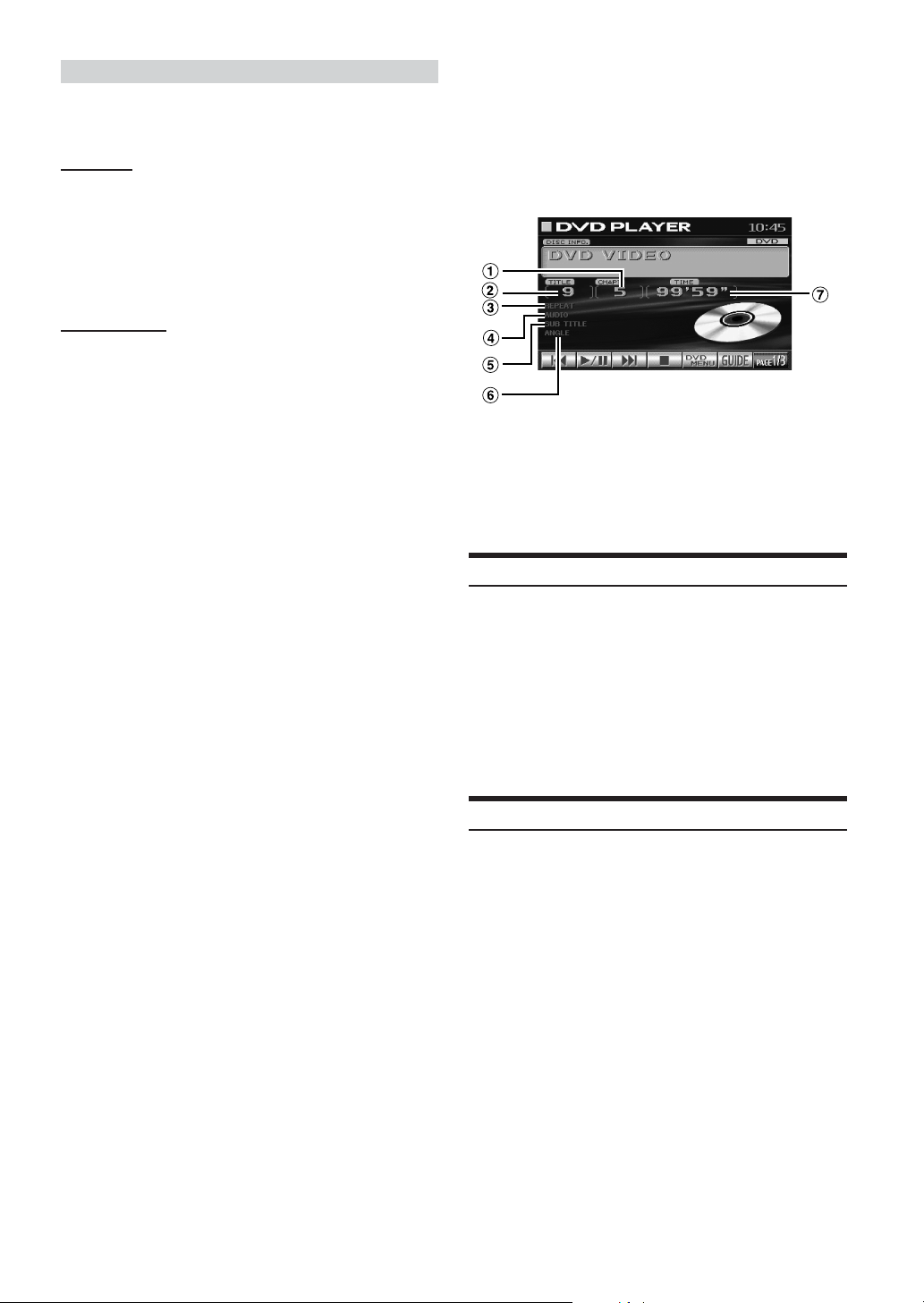
< ex. DVD display >
1 Current chapter number
2 Current title number
3 Repeat setting (Default setting-disc repeat)
4 Current audio stream
5 Current subtitle language
6 Current angle number
7 Elapsed playing time of current chapter
Stopping Playback (PRE STOP)
In some discs, the DVD menu screen can be displayed.
Operation from the remote control:
Press MENU, or press and hold TITLE for more than 2
seconds.
Operation from the main unit buttons I:
1 When DVD mode is selected, press 5 (DVD MENU).
The Function Guide is switched.
2Press 1 ('), 2 (.), 3 (/), 4 (;) or 5(ENTER) to
set the item.
Operation from the main unit buttons II:
1 When DVD mode is selected, press 7 (PAGE 1/3).
The Function Guide is switched.
2Press 5 (TITLE MENU).
3Press 1 ('), 2 (.), 3 (/), 4 (;) or
5 (ENTER) to set the item.
• By pressing 6 (DVD RETURN), the screen returns to
the previous one.
Press the stop button during playback to stop playback. That position
is stored in the memory.
Press 4 ( L ) once during playback.
1
“PRE STOP” is displayed.
Press 2 ( :/J ) in the PRE STOP mode.
2
Playback starts from the position at which it was stopped.
•For some discs, the position at which playback was stopped may
not be accurate.
Stopping Playback
Press 4 ( L ) twice or press once for more than 2
seconds during playback.
“STOP” is displayed, and playback stops.
•Playback stops even when L on the supplied remote control is
pressed for more than 2 seconds.
•Playback starts from the beginning when 2 ( :/J ) is pressed
while playback is stopped.
16-EN
Page 19
Fast-forwarding/Fast-reversing
Slow Motion Playback
During playback, press and hold 1 ( g ) (fast-
1
reverse) or 3 ( f ) (fast-forward).
When pressed for more than 1 second, the disc is
forwarded/reversed at double speed.
When held in 5 more seconds, the disc is forwarded/
reversed at 8 times the normal speed.
Release 1 ( g ) or 3 ( f ) to return to normal
2
playback.
• No sound or subtitles are played during fast-forwarding/fastreversing.
•For DVDs and video CDs with playback control (PBC), the menu
screen may reappear during fast-forwarding/fast-reversing.
Finding the Beginnings of Chapters or Tracks
During playback, press 1 ( g ) or 3 ( f ).
The chapter/track switches each time the button is pressed,
and playback of the selected chapter/track starts.
f : Press this to start playback from the beginning of
the following chapter or track.
g : Press this to start playback from the beginning of
the current chapter or track.
• Some DVDs do not have chapters.
Supplementary explanation
“Chapters” are divisions of movies or musical selections
on DVDs.
“Tra cks” are divisions of movies or musical selections on
video and music CDs.
When 3 ( f ) is pressed and held in while in the
1
pause mode, the 1/8th speed slow motion playback
mode is set.
When held in for 5 more seconds, the slow motion
speed switches to 1/2 the normal speed.
Release 3 ( f ) to pause, and press 2 ( :/J ) to
2
playback.
• No sound is played during slow motion playback.
•Reverse slow motion playback is not available.
•1/2, 1/8 are approximate speeds. The actual speed differs from disc
to disc.
Chapter/Track/Title Repeat Playback
Use this function to play the disc’s titles, chapters or tracks
repeatedly.
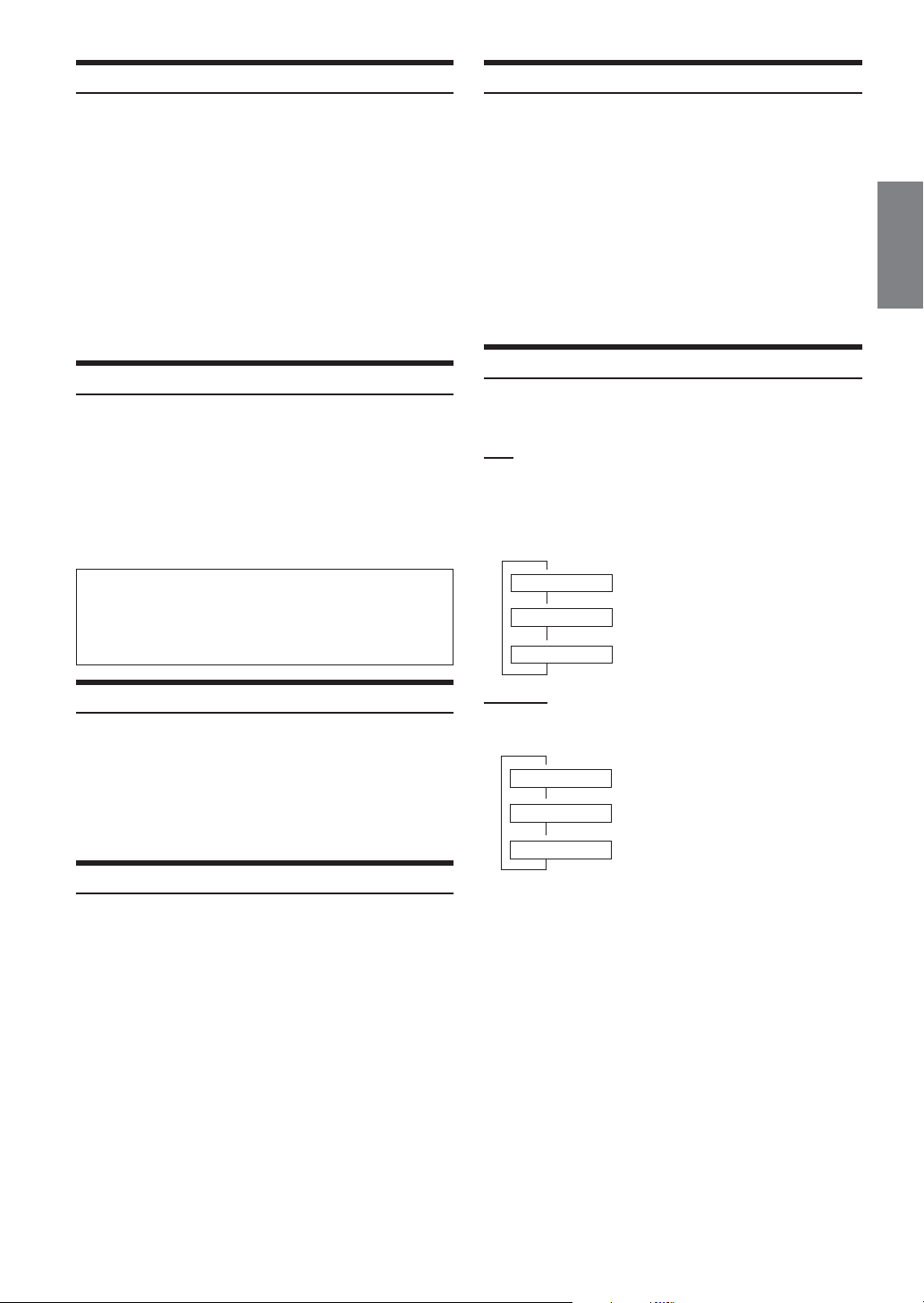
DVD
During playback, press 7 (PAGE 1/3).
1
Press 4 (REPEAT) on the main unit.
2
The repeat mode switches each time the button is
pressed.
9
REPEAT The chapter is played repeatedly.
9
REPEAT TITLE The title is played repeatedly.
9
REPEAT OFF The playback returns to normal mode.
Playing Still Frames (Pausing)
During playback, press 2 ( :/J ) once.
1
Press 2 ( :/J ) to resume playback.
2
• No sound is played during the still frame mode.
• The image or sound may stop temporarily when playback starts
from the pause mode. This is not a malfunction.
Frame-by-frame Playback
In the pause mode, press 3 ( f ).
1
The picture advances by one frame each time the button
is pressed.
Press 2 ( :/J ) to return to normal mode.
2
• No sound is played during frame-by-frame playback.
Video CD
During playback, press 4 (REPEAT) on the main unit.
The repeat mode switches each time the button is pressed.
9
REPEAT The track is played repeatedly.
9
REPEAT ALL The disc is played repeatedly.
9
REPEAT OFF The playback returns to normal mode.
• The track/disc repeat modes cannot be used on video CDs with
playback control (PBC). Follow the operation below to turn PBC
to OFF.
Operation from the remote control:
Press MENU.
Each press switches between PBC ON and OFF.
Operation from the main unit button:
1 When the Video CD mode is selected, press 5(PBC).
Each press switches between PBC ON and OFF.
2Press 1 ( g ) or 3 ( f ) to select a menu item.
•For some discs it is not possible to switch the repeat mode.
17-EN
Page 20

Searching by Title Number (DVD only)
Use this function to easily find positions on the DVD using the
DVD’s titles.
When the playback stops, input the number of the
1
title you want to play using the number buttons
(“0” to “9”) on the supplied remote control.
• This function cannot be used on discs on which no title
numbers are recorded.
•Press DEL. to delete the last digit in the title number. Press
and hold DEL. for at least 2 seconds to clear all title
numbers.
•Press RTN to cancel the title search mode and resume normal
playback.
• The playback starts automatically for two digit title numbers
even if ENTER in procedure 2 is not pressed.
•Playback starts from the beginning of the chapter/track
number in the state of PRE STOP.
• Some disc may not accept any operation.
Press ENTER.
2
Playback starts from the selected title number.
• If the track number is a 2-digit number, playback starts
automatically even if ENTER is not pressed in step 2.
• If the chapter number is a 3-digit number, playback starts
automatically even if ENTER is not pressed in step 2.
•Press DEL. to delete the last digit in the chapter/track number.
Press and hold DEL. for at least 2 seconds to clear “Chapter” and
“Track” numbers.
•Press RTN to cancel the chapter/track search mode and resume
normal playback.
•With video discs containing playback control (PBC), the
“searching directly by track number” function is not available
while PBC is ON. Follow the operation below to turn PBC to OFF.
Operation from the remote control:
Press MENU.
Each press switches between PBC ON and PBC OFF.
Operation from the main unit button:
1 When the Video CD mode is selected, press 5 (PBC).
Each press switches between PBC ON and PBC OFF.
2Press 1 ( g ) or 3 ( f ) to select a menu item.
• If the chapter/track number is known, you can search directly using
the number buttons (“0” to “9”) during playback mode, PRE
STOP mode, etc.
Switching the Angle (DVD only)
Searching Directly by Chapter or Track
Number
Use this function to easily move to the beginnings of the chapters or
tracks on the disc.
Press 5 (DVD MENU) except when playback
1
stops.
DVD menu screen is displayed.
Press 7 (PAGE 1/3) twice.
2
The Function Guide is switched.
Press 1 (') through 4 (;) to select a chapter or
3
a track to be played.
Press 5 (ENTER).
4
Playback starts from the selected chapter or track.
• While the DVD title menu is displayed also by pressing 5 (TITLE
MENU), in some disc, either 5 (DVD MENU) or 5 (TITLE
MENU) may not be effective for it.
• This function cannot be used on discs on which no chapter
numbers are recorded.
Operation from the remote control
Except during the stop mode, input the number of
1
the chapter or track you want to play using the
number buttons (“0” to “9”).
Press ENTER.
2
Playback starts from the selected chapter or track.
On DVDs in which scenes have been filmed from multiple angles, the
angle can be switched during playback.
During playback, 7 (PAGE 1/3).
1
Press 2 (ANGLE).
2
The angle switches between the angles recorded on the
disc each time the button is pressed.
• Some time may be required for the angle to change.
•Depending on the disc, the angle may switch in one of two ways.
- Seamless: The angle switches smoothly.
- Non-seamless: When the angle is switched, a still picture is
displayed first, after which the angle switches.
Switching the Audio Tracks
DVDs can have up to 8 different audio tracks. These alternate tracks
can be switched during playback.
During playback, 7 (PAGE 1/3).
1
Press 1 (AUDIO).
2
The sound switches between the alternate audio tracks
recorded on the disc each time the button is pressed.
• The alternate track selected becomes the default setting every time
the power is turned on or the disc is replaced. If the disc does not
include that track, the disc’s default language is selected instead.
• Not all discs will allow changing the alternate audio tracks during
playback. In these cases, select audio tracks from the DVDs menu.
• There may be a delay before the selected alternate track begins to
play.
• Video CDs with multiplex audio
During playback, press AUDIO on the supplied remote
control.
The left and right channels will be output as shown in the figure
below, each time the button is pressed.
LL RR LR
18-EN
Page 21

Switching the Subtitles (Subtitle Language)
(DVD only)
With DVDs on which multiple subtitle languages are recorded, the
subtitle language can be switched during playback; moreover,
subtitles can be hidden.
During playback, press 7 (PAGE 1/3).
1
Press 3 (SUB.T).
2
The subtitle switches between the languages recorded on the
disc each time the button is pressed; moreover, the subtitle is
turned OFF.
• There may be a delay before the selected subtitle appears.
• Not all discs will allow changing the subtitles during playback. In
these cases, select subtitles from the DVDs menu.
• The subtitle language selected becomes the default setting every
time the power is turned on or the disc is replaced. If the disc does
not include that language, the disc’s default language is selected
instead.
•For some discs, the subtitles will be displayed even when this is set
to off.
Switching from the disc menu
For some discs, the audio language, angle and subtitles can
be switched from the disc menu.
Operation from the remote control
1Press MENU or press and hold TITLE (for at least 2
seconds), select the item, then press ENTER.
2 Use the Joystick to select the language or angle, then
press ENTER.
(For some discs, they can be selected using the
number buttons (“0” to “9”) while the language or the
angle menu is displayed.)
Operation from the main unit buttons I:
1 When DVD mode is selected, press 5(DVD MENU).
The Function Guide is switched.
2Press 1 ('), 2 (.), 3 (/), 4 (;) or 5 (ENTER) to
set the item.
Operation from the main unit buttons II:
1 When DVD mode is selected, press 7(PAGE 1/3).
The Function Guide is switched.
2Press the 5 (TITLE MENU).
3Press 1 ('), 2 (.), 3 (/), 4 (;) or 5 (ENTER) to
set the item.
• By pressing 6 (DVD RETURN), the screen returns to the
previous one.
Displaying the Disc Status for DVD
Use the procedure described below to display the status (title number,
chapter number, etc.) of the currently playing DVD on the monitor
screen.
During playback, press any one of the function
1
buttons 1~7.
The Function Guide is displayed.
Press and hold 6 (GUIDE) for more than 2
2
seconds.
The playback status is displayed.
The display returns to the previous one in 10 seconds.
Displaying the Disc Status for Video CD
Use the procedure described below to obtain an on-screen display of
the status (track number, etc.) of the currently playing video CD.
During playback, press any one of the function
1
buttons 1~7.
The Function Guide is displayed.
Press and hold 6 (GUIDE) for more than 2
2
seconds.
The playback status is displayed.
The display returns to the previous one in 10 seconds.
19-EN
Page 22
Sound Setting
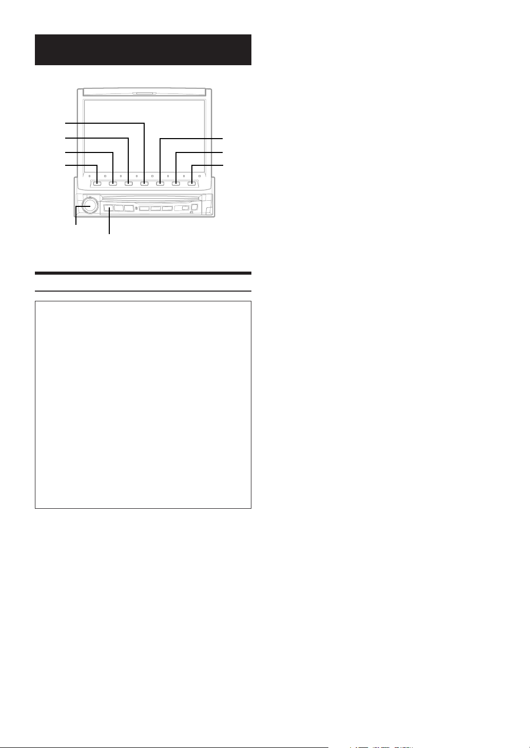
4
3
2
1
Rotary encoder
SOURCE/POWER
Setting the MX mode
To display the Audio processor mode screen:
To watch a video source, your vehicle must be parked with
the ignition key in the ACC or ON position. To do this, follow
the procedure below.
1. Bring your vehicle to a complete stop at a safe
location. Engage the parking brake.
2. Keep pushing the foot brake and release the parking
brake once then engage it again.
3. When the parking brake is engaged for the second
time, release the foot brake.
•For automatic transmission vehicles, place the transmission
lever in the Park position.
Now, the locking system for the Audio processor mode
operation has been released. Engaging the parking brake
can reactivate the Audio processor mode, as long as the
car's ignition has not been turned off. It is not necessary to
repeat the above procedure (1 through 3), of “To display
the Audio processor mode screen.”
Each time the ignition is turned OFF, perform the procedure
of “To display the Audio processor mode screen.”
MX (Media Xpander) makes vocals or instruments sound distinct
regardless of the music source. The radio, CD, and MP3, will be able
to reproduce the music clearly even in cars with a lot of road noise.
Press SOURCE/POWER.
1
The main menu is displayed.
Press 4 (A.PROC).
2
A.PROC (Audio processor) list screen is displayed.
Turn the Rotary encoder to select “Media
3
Xpander.”
OFF: MX mode is canceled for all music sources.
ON: The selected MX mode is turned on.
5
6
7
After pressing 2 (ON), press 3 (SETUP).
4
MX list screen is displayed.
Turn the Rotary encoder to select your desired
5
MX mode.
The screen shows the *Function Guide.
*Displays the function assigned for each button.
Press the Function button to switch the setting.
6
The level of the audio source can be adjusted. It is after
switching the audio source that the MX mode is applied.
MX CD (OFF, CD1 to 3)
The large quantity of uncompressed CD data is
processed to reproduce the sound with more clarity.
MX MP3 (OFF, MP3 1 to 3)/MX XM (OFF, XM1 to 3) /MX
MD (OFF, MD1 to 3)
This corrects information that was omitted at the time of
compression. This reproduces a well-balanced sound
close to the original.
MX FM (OFF, FM1 to 3)
The medium to high frequencies become more clear, and
produces well balanced sound in all the bands.
MX DVD (OFF, MOVIE 1 to 2)
The dialog portion of the video is reproduced more
clearly.
(DVD MUSIC)
This disk contains a large quantity of data such as a
music clip. MX uses this data to reproduce the sound
accurately.
MX AUX 1 to 3 (OFF, MP3, MOVIE, MUSIC)
Choose the MX mode (MP3, MUSIC, or MOVIE) that
corresponds to the media connected.
By pressing 7 (RETURN) , return to the previous
7
screen.
• When OFF is selected, MX effect of each MX mode will be off.
• Each music source, such as radio, CD and MP3 can have its own
MX setting.
• XM, MD is displayed only when each product is connected.
•AUX is displayed when an external input device is connected and
LEVEL LOW or LEVEL HIGH is selected in "Setting the AUX
mode" (page 33).
• MX mode does not function for AM radio when MX is ON.
• If the unit is connected to an audio processor with the MX function,
such as PXA-H700, etc., the MX processing can be applied to the
audio processor. In this case the audio processor needs to be
adjusted. For details, refer to the Owner’s Manual of the audio
processor.
20-EN
Page 23
Setting the Bass Engine
The following steps 1 to 7 are common operations to each
“Setting item” of bass engine Setup. Refer to each section for
details.
• The settings of the bass level will be individually memorized for
each source (FM, AM, XM, CD, etc.) until the setting is changed.
Once you set Bass frequency and Bass Band Width for one of
sources (FM, AM, XM, CD, etc.), this setting becomes effective for
all those sources. Depending on the connected devices, some
functions and display indications do not work.
• This function is inoperable when DEFEAT is ON.
1 Press SOURCE/POWER.
The main menu screen is displayed.
2 Press 4 (A.PROC).
A.PROC (Audio processor) list screen is displayed.
3 Tur n the Rotary encoder to select “bass engine.”
4 Press 1 (SETUP) .
The bass engine list screen is displayed.
5 Tur n the Rotary encoder to select your desired
sound setting.
The screen shows the *Function Guide.
*Displays the function assigned for each button.
Setting items
BASS ↔ TREBLE ↔ BASS FOCUS ↔ TIME
CORRECTION ↔ CROSSOVER
6 Press the Function button to switch the setting.
7 Press 7 (RETURN) .
The screen returns to the previous one.
Setting the Bass Control
Setting item: BASS
Setting contents: FREQ.DN / UP / LEVEL DN / UP / WIDTH DN /
UP
You can change the bass frequency emphasis to create your own tonal
preference.
Setting the bass center frequency:
Press 1 (FREQ. ;DN) or 2 (FREQ. UP :) to select the
desired bass center frequency.
Setting the Treble Control
Setting item: TREBLE
Setting contents: FREQ.DN / UP / LEVEL DN / UP
You can change the treble frequency emphasis to create your own
tonal preference.
Setting the treble center frequency:
Press 1 (FREQ. ;DN) or 2 (FREQ. UP :) to select the
desired treble center frequency.
10kHz ? 12.5kHz ? 15.0kHz ? 17.5kHz
Emphasizes the displayed treble frequency ranges.
Setting the treble level:
Press 3 (LEVEL ;DN) or 4 (LEVEL UP :) to select the
desired treble level (–7 - +7).
You can emphasize the treble frequency.
• The settings of the treble level will be individually memorized for
each source (FM, AM, XM, CD, etc.) until the setting is changed.
Once you set the treble frequency for one of sources (FM, AM, XM,
CD, etc.), this setting becomes effective for all those sources.
Depending on the connected devices, some functions and display
indications do not work.
• This function is inoperable when DEFEAT is ON.
60Hz ? 70Hz ? 80Hz ? 90Hz ?
100Hz ? 130Hz ? 150Hz ? 180Hz
Emphasizes the displayed bass frequency ranges.
Setting the bass Level:
Press 3 (LEVEL ;DN) or 4 (LEVEL UP :) to select the
desired bass Level (-7 – +7).
You can emphasize or weaken the bass frequency.
Setting the bass Band Width (Q-Factor):
Press 5 (WIDTH ;DN) or 6 (WIDTH UP :) button to select
the desired bass Band Width.
Q 1 ? Q 2 ? Q 3 ? Q 4
(Narrow)'
Changes the bass boost band width to wide or narrow. A wide
setting will boost a wide range of frequencies above and
below the center frequency. A narrower setting will boost only
frequencies near the center frequency.
⋅⋅⋅⋅⋅⋅⋅⋅⋅⋅⋅⋅⋅⋅⋅⋅⋅⋅⋅⋅⋅⋅⋅⋅⋅⋅⋅⋅
;(Wide)
21-EN
Page 24
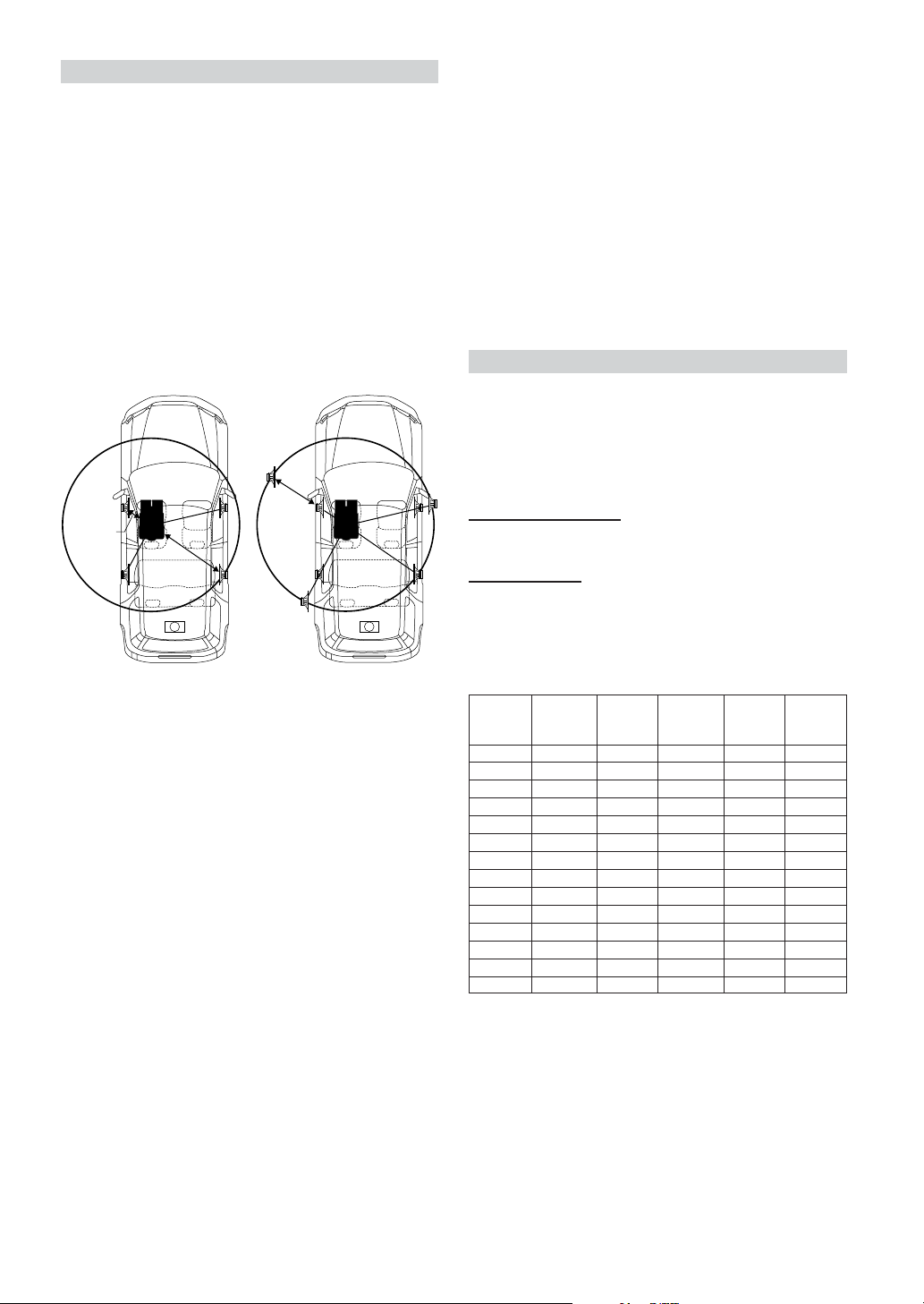
About the Time Correction
The distance between the listener and the speakers in a car vary
widely due to the special conditions of the mobile environment. This
difference in the distances from the speakers to the listener creates a
shift in the sounds image and frequency characteristics. This is caused
by the time delay between the sound reaching the listener’s right
versus left ear.
To correct this, the IVA-D901 is able to delay the audio signal to the
speakers closest to the listener. This effectively creates a perception of
increased distance for those speakers. The listener can be placed at an
equal distance between the left and right speakers for optimum
staging.
The adjustment will be made for each speaker in a step of 0.1 ms.
Example 1. Listening Position: Front Left Seat
Adjust the time correction level of the front left speaker to a
high value and the rear right to zero or a low value.
5.1ms
0.5m
2.25m
∗
∗
Example 2. Listening Position: All Seats
Adjust the time correction level of each speaker to almost the
same level.
Sit in the listening position (driver’s seat, etc.) and
1
measure the distance (in meters) between your
head and the various speakers.
Calculate the difference between the distance to
2
the farthest speaker and the other speakers.
L = (distance to farthest speaker) – (distance to other
speakers)
Divide the distances calculated for the speakers by
3
the speed of sound (343 m/s (765 mph) at 20˚C).
These values are the time correction values for the
different speakers.
Bass Focus
Setting item: BASS FOCUS
Setting contents: TIME DN / UP / FRONT / LEFT / RIGHT /
REAR
The time difference between the front-rear/left-right speakers, can be
adjusted at the same time. With an initial delay of 0.1 ms for each of
the 0 to 99 steps, audible time correction can be done.
Selecting the speaker:
Select the speaker among 3 (FRONT) through 6 (REAR).
Setting the step:
Press 1 (TIME ;DN) or 2 (TIME UP:) to set the step.
• Any manual time correction adjustments will also affect
corrections made for bass focus.
Tips
*
Subwoofer speaker
You cannot change the time correction value for the
subwoofer, but you can set the subwoofer's apparent position
to the front by adjusting the time correction value of the front
and rear speakers.
For details, refer to the “Tips” on page 23.
Here we calculate the time correction value for the front left
speaker in the diagram above.
Conditions:
Farthest Speaker – listening position: 2.25 m (88-9/16")
Front left speaker – listening position: 0.5 m (19-11/16")
Calculation: L = 2.25 m – 0.5 m = 1.75 m (68-7/8")
Time correction = 1.75 ÷ 343** × 1000 = 5.1 (ms)
** Speed of sound: 343 m/s (765 mph) at 20˚C
The sound is not balanced because the distance between the
listening position and the various speakers is different.
The difference in distance between the front left speaker and
the rear right speaker is 1.75 m (68-7/8").
Time correction eliminates the differences in the time required
for the sound to reach the listening position.
The time of the front left speaker is corrected by 5.1 ms so that
its sound reaches the listening position at the same time as the
sound of other speakers.
In other words, giving the front left speaker a time correction
value of 5.1 ms makes it seem as if the distance to the front left
speaker is the same as the distance to the farthest speaker.
Time Difference Table
Number
of Steps
0 0.0 14 1.4 28 2.8
1 0.1 15 1.5 29 2.9
2 0.2 16 1.6 30 3.0
3 0.3 17 1.7 31 3.1
4 0.4 18 1.8 32 3.2
5 0.5 19 1.9 33 3.3
6 0.6 20 2.0 34 3.4
7 0.7 21 2.1 35 3.5
8 0.8 22 2.2 36 3.6
9 0.9 23 2.3 37 3.7
10 1.0 24 2.4 38 3.8
11 1.1 25 2.5 39 3.9
12 1.2 26 2.6 40 - 98 4.0 - 9.8
13 1.3 27 2.7 99 9.9
Time
Difference
(ms)
Number of
Steps
Time
Difference
(ms)
Number of
Steps
Time
Difference
(ms)
22-EN
Page 25
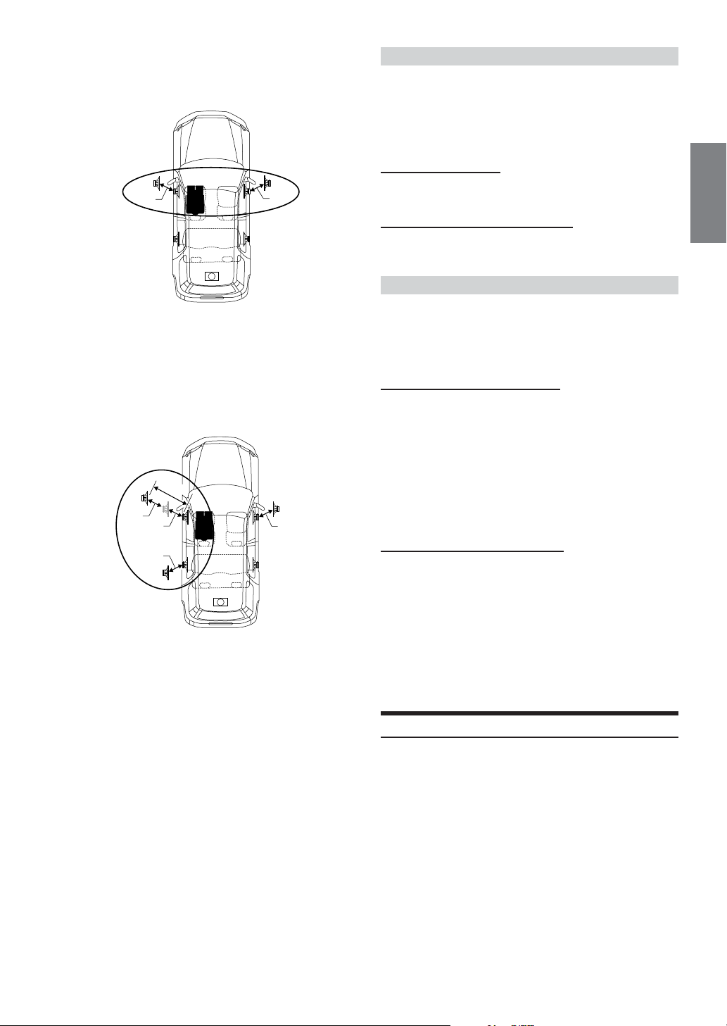
Example of Bass Focus Setting
1After entering corrections for the front (left and right)
speakers in STEP 15, the time difference is 1.5 ms for
both front-left and front-right speakers.
1.5ms
∗
1.5ms
Time Correction
Setting item: TIME CORRECTION
Setting contents: TIME DN/UP/FRONT-LEFT/FRONT-RIGHT/
REAR-LEFT/REAR-RIGHT
Before performing the following procedures, refer to “About the
Time Correction” (page 22).
Selecting the speaker:
Select the speaker among 3 (FRONT-LEFT) through
6 (REAR-RIGHT).
Adjusting the time correction value:
Press 1 (TIME ;DN) or 2 (TIME UP:) to adjust the time
correction value (0.0 to 9.9).
Adjusting the Built-in Crossover
2After entering corrections for the left (front and rear)
speakers in STEP 15, the time difference becomes 3.0
ms** for the front left speaker and 1.5 ms for the left
rear speaker.
** Because the time difference was already set to 1.5 ms for the
front left speaker in STEP 1, the additional correction in
STEP 15 makes the time difference of the front left speaker 3.0
ms.
3.0ms
1.5ms
1.5ms
1.5ms
∗
Tips
*
Subwoofer speaker
Delay (turn the rotary encoder) the audio signal to the front
(left and right) speakers to make the apparent position of the
subwoofer to be at the front. In doing this, the apparent
position between the front (left and right) speakers and
subwoofer will appear equal to the driver. After performing
above, you can change the positions of left and right speakers
by delaying the time.
1.5ms
Setting item: CROSSOVER
Setting contents: LPF DN / UP / HPF DN / UP
The High and Low Pass Filters on this unit can be adjusted to
suit your personal taste.
LPF (Setting the Low Pass Filter):
Press 1 (LPF ;DN) or 2 (LPF UP:) to adjust LPF.
FLAT (OFF) ↔ 80Hz ↔ 120Hz ↔ 160Hz
Outputs all frequencies lower than that selected according to
your preference.
(Only available when using the subwoofer output from this
unit.)
• When the subwoofer output of this unit is turned OFF, LPF and
phase are deactivated.
HPF (Setting the High Pass Filter):
Press 3 (HPF ;DN) or 4 (HPF UP:) to adjust HPF.
FLAT (OFF) ↔ 80Hz ↔ 120Hz ↔ 160Hz
Outputs all frequencies higher than that selected according to
your preference.
• If HPF, LPF, bass control and treble control are all set to ON,
depending on the bass control and treble control settings, you may
not be able to reinforce the sound effect.
• Except when the HPF and LPF is turned OFF, the subwoofer is in
monaural mode.
Subwoofer On and Off
1 Press SOURCE/POWER.
The main menu is displayed.
2 Press 4 (A.PROC).
The A.PROC (Audio processor) list screen is displayed.
3 Tur n the Rotary encoder to select
“SUBWOOFER.”
4 Press the Function button to select your desired
setting.
OFF: Subwoofer output is off.
0°: Subwoofer output is on, and the phase is 0°.
180°: Subwoofer output is on, and the phase is 180°.
23-EN
Page 26
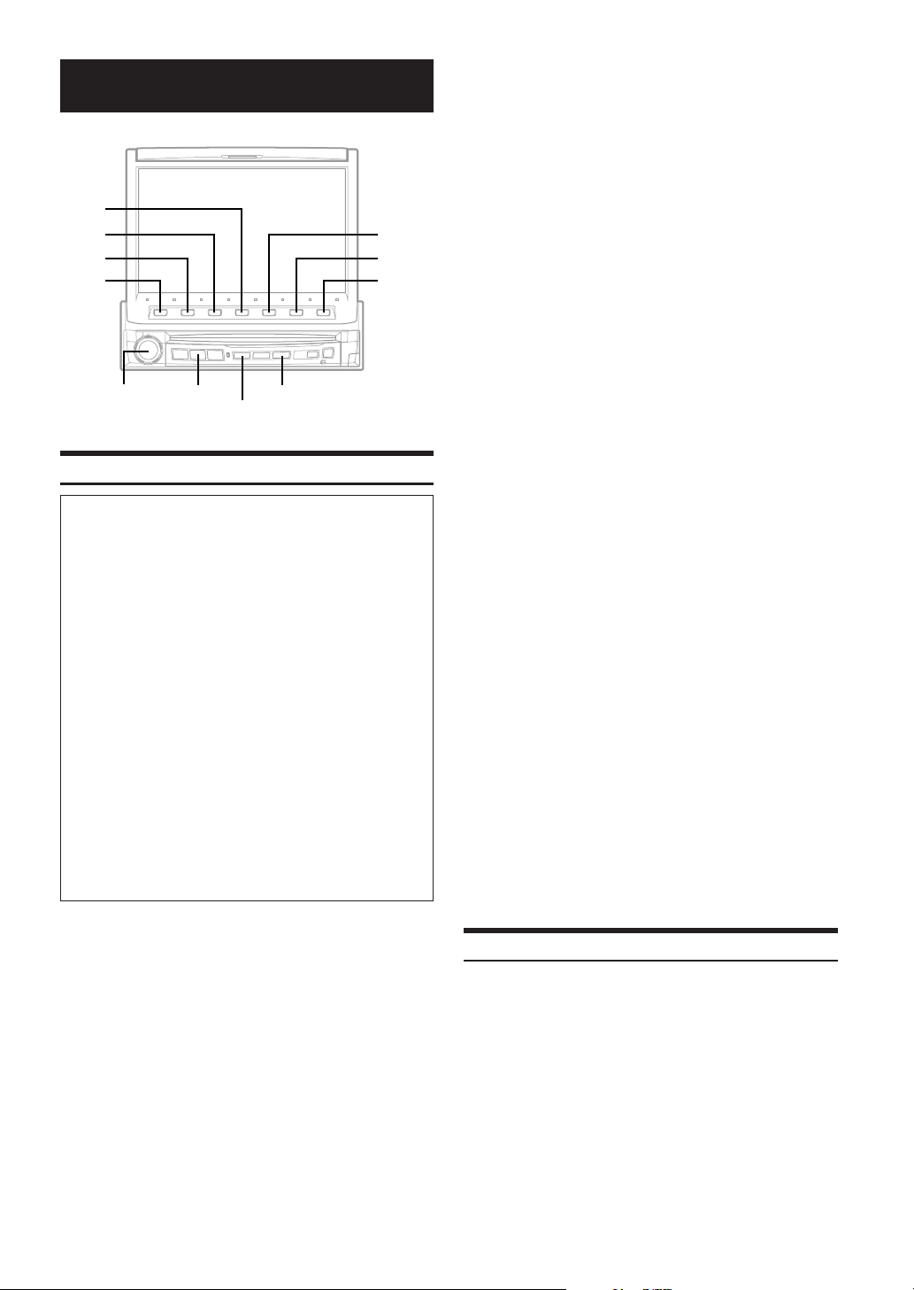
Other Useful Features
4
3
2
1
Rotary encoder
BAND
LIST/INPUT
REAR
Titling Radio Stations/Discs
To display the Title Inputting screen:
To watch a video source, your vehicle must be parked with
the ignition key in the ACC or ON position. To do this, follow
the procedure below.
1. Bring your vehicle to a complete stop at a safe
location. Engage the parking brake.
2. Keep pushing the foot brake and release the parking
brake once then engage it again.
3. When the parking brake is engaged for the second
time, release the foot brake.
•For automatic transmission vehicles, place the transmission
lever in the Park position.
Now, the locking system for the Title Inputting mode
operation has been released. Engaging the parking brake
can reactivate the Title Inputting mode, as long as the car's
ignition has not been turned off. It is not necessary to
repeat the above procedure (1 through 3), of “To display
the Title Inputting mode screen.”
Each time the ignition is turned OFF, perform the procedure
of “To display the Title Inputting mode screen.”
•Trying to access this screen while driving will display the
warning-CAN'T OPERATE WHILE DRIVING.
You can title radio stations and Discs (CD, Video CD). This manual
describes how to title radio stations.
(You cannot title MP3 discs, except in an MP3 compatible CD
changer.)
Activate the radio mode.
1
Tune in a radio station you wish to title.
Press and hold LIST/INPUT for at least 2
2
seconds.
The Title Inputting screen appears in the display and
characters are displayed at the bottom menu.
5
6
7
Turn the Rotary encoder and select the desired
3
character for the first position.
To change between upper case, lower case, numeral and
symbol, press 3 (A/1). Each press changes the bottom
menu.
When the character for the first position has been
4
selected, press the Rotary encoder.
The first character has been memorized at the first
position. See "notes at the right" on this page.
Repeat steps 3 and 4 to enter the rest of
5
characters.
You can input up to 16 characters for titling one radio
station (or Disc).
When titling has been completed, press
6
6 (WRITE) to store the title in memory.
The display changes to the Radio mode.
To title other stations (or disc), repeat this
procedure. You can title up to 100 (max.) stations
and CDs combined. The input titles will be
displayed when a station (or Disc) titled is
selected.
• If the memory capacity for radio station titles is full and if you
attempt to title a new station, the oldest title will be erased to make
room for the new one. To delete a title, select the title you want to
delete, then select "SPC" (space) and press 6 (WRITE).
• When 1 (; BACK) or 2 (NEXT :) is pressed, the cursor moves
to the left or right on the input titles.
• If an incorrect character has been entered, select "SPC" (space)
and input a new character or press 5 (DELETE) to delete the
previous character. Press 4 (CLEAR) while inputting the titles to
erase all the characters you have input.
•Pressing 7 (RETURN) in the Title Input mode changes the
display back to the previous display.
• When the memory is full, "FULL DATA" is displayed for 2 seconds.
If the new title is input to the full memory, the title input at first is
deleted and the newly input title is memorized.
•You can title the VIDEO CD/CD while it is in optional DVD player
or DVD changer. The title you entered is displayed in the
"Displaying the Title List" (pages 24 and 25).
(Do not operate while driving. Stop the car, then use this
operation.)
• Immediately after inputting titles or changing the settings
of Setup mode or Display mode (while the system is
inputting the titles or data automatically) do not turn the
ignition key (engine key) to OFF.
Otherwise, the title may not be written, or the settings may
not be changed.
Displaying the Title List
The titled radio programs or discs can be displayed in the list. As for
CD TEXT disc, the disc name, track name, etc., are displayed.
During MP3 play, the folder names and file names are displayed. It is
easy to tune in to the desired radio program or to play the desired
disc.
(In Radio mode for example)
In the Radio mode, press LIST/INPUT.
1
The STATION TITLE LIST display appears.
Turn the Rotary encoder to move the cursor to
2
your desired title.
24-EN
Page 27

Press the Rotary encoder.
3
The selected title starts to play, and the screen returns to
the Radio mode.
To display the folder list or the file list of MP3 disc
1Press 6 (NEXT :) while the disc title list is displayed.
The folder title list of the selected disc is displayed.
2Turn the Rotary encoder to select the desired folder.
3Press 6 (NEXT :) to display the file (track) list of the
selected folder.
To return to the previous screen, press 5 (; BACK).
4Turn the Rotary encoder to select the desired file
(track).
5Press the Rotary encoder. The selected title is played
back.
• By pressing 1 (DISC), Disc Title list display appears.
• By pressing 3 (XM), XM's Category list appears (only with an
XM receiver connected).
• If the disc is not titled, the display shows "NO TITLE." If no disc is
loaded, the display shows "NO DISC."
•Pressing LIST/INPUT or 7 (RETURN) while the disc title list is
displayed, returns to the previous screen.
•To directly go to the preset radio station list screen, press
2 (RADIO). Then, press BAND to change the radio band.
Setting of Scrolling
When the discs are titled, the list of the titled can be scrolled.
CD text, folder name, file name and ID3 tag also be able to be
scrolled.
During play of the disc, press 6 (SCROLL) for
1
more than 2 seconds.
AUTO scroll mode starts and the disc titles and the track
titles are continuously scrolled one after the other.
By pressing 6 (SCROLL) for more than 2
2
seconds, AUTO scroll is canceled.
By pressing 6 (SCROLL) after AUTO scroll is canceled,
disc titles and track titles are simultaneously scrolled
once.
When a track reaches to its end, the list is scrolled once.
Description of "Title" and "Text":
Title: This unit allows you to title (name) Discs (page 24).
Text: Some CDs have pre-recorded text information for
the CD/track names etc.
• Depending on the character styles, characters may not be
displayed correctly.
•Text can only be displayed on CD changers that are enabled with
CD TEXT.
• If both the disc and track titles are unavailable, the display will
show "NO TITLE."
Rear Entertainment Function
The rear entertainment function independently routes different
sources to the front and the rear inside a car. For example, while
listening to the radio or other audio source in the front, DVD can be
enjoyed in the rear with the optional rear monitor and headphones.
Press SOURCE/POWER.
1
The main menu is displayed.
Press 3 (R.SEL).
2
Rear Select display appears.
• The REAR button also switches the screen to the Rear Select display.
• This function cannot be used when MONITOR OUT 1 or 2 is set to
OFF in the SYSTEM SETUP.
Press 1 (REAR 1) or 2 (REAR 2).
3
When only one external monitor is connected, “REAR” is
displayed.
REAR 1: The external monitor connected to AUX OUT1.
REAR 2: The external monitor connected to AUX OUT2.
Turn the Rotary encoder to select your desired
4
source (the auxiliary intput or built-in DVD).
•
If this item is set to “INFO. DISP”, the rear entertainment function will be off.
• When the “Setting the AUX Mode” (page 33) is set to OFF, the
auxiliary source is not displayed.
• When TV is selected in AUX IN 3 MODE, TV is displayed.
• When FRONT LINK is selected, the same pictures with the front
main source screen are output. The sound is not output.
Press the Rotary encoder.
5
The selected source for REAR 1 and REAR 2 is displayed
respectively.
Switching the function of the remote sensor
For the remote control operation, the remote sensor of the external
unit (monitor, etc.) can be switched as you prefer.
Press REAR for more than 2 seconds.
6
It enters to the monitor switching mode in which the prior
remote control can be selected.
Press REAR.
7
Each time it is pressed, the external monitor which has a
priority to the remote control operation is changed. The
icon indicator (REAR 1 or REAR 2)* of the selected
monitor is displayed.
REAR1: The remote sensor of the external monitor
REAR2: The remote sensor of the external monitor
* When only one external monitor is connected and the output
The monitor switching mode is canceled by pressing
REAR for more than 2 seconds.
• When the remote sensor on the external monitor is effective,
pressing sound (beep sound) does not come out.
• When there is an external interruption, the external interruption
icon is prior to the others.
• When you watch the built-in DVD in IVA-D901 (front monitor) and
in the rear monitor, the On Screen display of the rear monitor
(PLAY, PAUSE, FAST FWD, etc.) is not displayed.
connected to AUX OUT1 is effective, and the
remote control can operate only the source
selected for the terminals.
connected to AUX OUT2 is effective, and the
remote control can operate only the source
selected for the terminals.
is set to ON, the REAR icon indicator is displayed. (See
“Setting of the External Monitor Output,” page 34.)
Continued
25-EN
Page 28
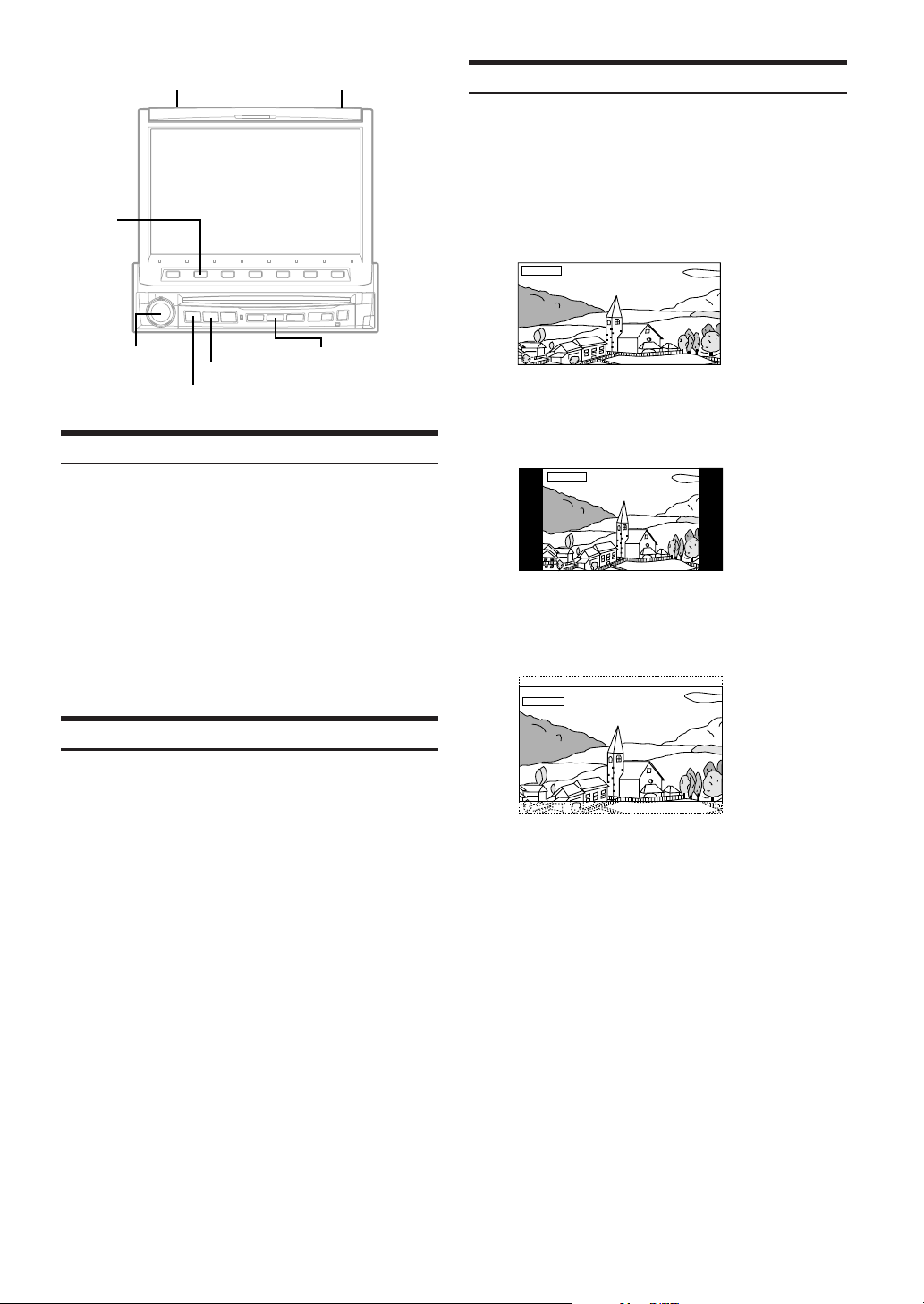
DEMO
2
MUTE/DISP. OFF
Switching Display Modes
After carrying out the steps 1 to 3 of "To display the DVD mode
Screen" explained on page 28, perform the operation described below.
Press and hold WIDE/DISP for at least 2 seconds in
the visual source.
Each press changes the display modes as follows:
MODE 1 → MODE 2 → MODE 3 → MODE 1
(WIDE) (NORMAL) (CINEMA) (WIDE)
MODE1
Rotary encoder
WIDE/DISP.
SOURCE/POWER
SPE.ANA.
Blackout Mode On and Off
When Blackout mode is turned on, the display will turn off to reduce
power consumption.
This additional power enhances the sound quality.
Press and hold MUTE/DISP. OFF for at least 2
seconds to start the blackout mode.
By doing so the display will turn off.
• If any button on the unit is pressed during Blackout mode, the
function will be displayed for 5 seconds to show the operation
before returning to Blackout mode.
To cancel Blackout mode, press and hold MUTE/DISP. OFF for
at least 2 seconds.
Demonstration
This unit has a Demonstration feature which simulates the display
functions.
Press and hold DEMO for at least 2 seconds.
1
Each press toggle between DEMO ON and DEMO OFF.
Press and hold DEMO for at least 2 seconds to
2
return to normal operation.
In Mode 1 (Wide), the monitor displays a normal picture wider
to fit in a wide-screen monitor by evenly stretching out the
picture horizontally.
MODE2
In Mode 2 (Normal), the monitor displays a normal picture at
the center of the screen with a vertical black band at each
side.
MODE3
In Mode 3 (Cinema), the monitor displays a normal picture by
stretching out the picture horizontally and vertically. This mode
is good for displaying a cinema type picture at the 16 : 9 ratio.
26-EN
Page 29
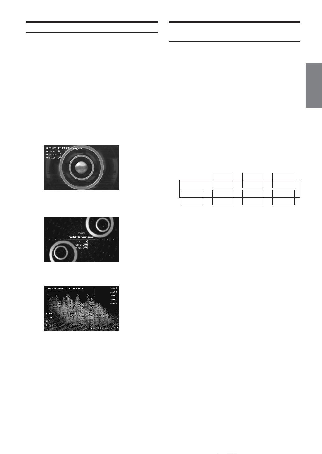
Displaying the Spectrum Analyzer
Depending on the external audio processor connected to the unit, this
function may not work properly.
When one of the sources except for the video
1
source is selected, press SPE.ANA. to turn on the
spectrum analyzer mode.
Each time you press SPE.ANA, the spectrum
2
analyzer modes change.
SCAN ; MODE 1 ; MODE 2 ; MODE 3 ; SCAN
There are three modes, select your desired mode to
match the music being played.
Mode 1:
This mode emphasizes the rhythmical bass sound and
gives an image of vivid low frequencies.
Mode 2:
This mode is suitable to vocal song music.
Switching the Visual Source Only
(Simul Function)
You can watch the video portion of another source while listening to
the current source.
•After carrying out the steps 1 to 3 of "To display the DVD mode
Screen" explained on page 28, perform the operation described
below.
Press SOURCE/POWER.
1
The main menu appears on the display.
Press 2 (V. SEL) to select the video portion.
2
Turn the Rotary encoder and select your desired
3
video source.
When "INFO.DISP" is selected, the main display shows
playing disc (DVD, Video CD) status or auxiliary intput
(AUX, TV, etc.) status.
If the spectrum analyzer has been set in "Displaying
Spectrum Analyzer (page 27)", the spectrum analyzer
mode display appears here.
(Example)
Picture DVD
---
INFO.DISP
Voice DVD DVD DVD
CAMERA
DVD DVD DVD DVD
NAV. AUX3 AUX2
////
AUX1
∗
Mode 3:
This mode can be used for any genre of music.
SCAN Display
It displays mode1 to mode 3 repeatedly.
To deactivate the spectrum analyzer mode, press
3
SPE.ANA. for at least 2 seconds.
* If a DVD player is connected, you can receive the DVD picture/
sound.
DVD player (DVA-5205) or DVD changer (DHA-S680) is
connected:
Press and hold V.OUT on the remote control supplied with the
DVD player or DVD changer for more than 2 seconds. The picture
and sound of the DVD will be output.
The DVA-5210 is connected:
Press V.OUT on the remote control (included with the DVA-5210)
to output DVD picture/sound.
• The Simul function cannot be used when the Audio source is in the
navigation mode.
• By pressing V.SEL for more than 2 seconds, the Simul function is
canceled. (Even if 2 (V. SEL) of the function button is pressed for
more than 2 seconds, it is not canceled.)
Press the Rotary encoder to execute the
4
selection.
27-EN
Page 30
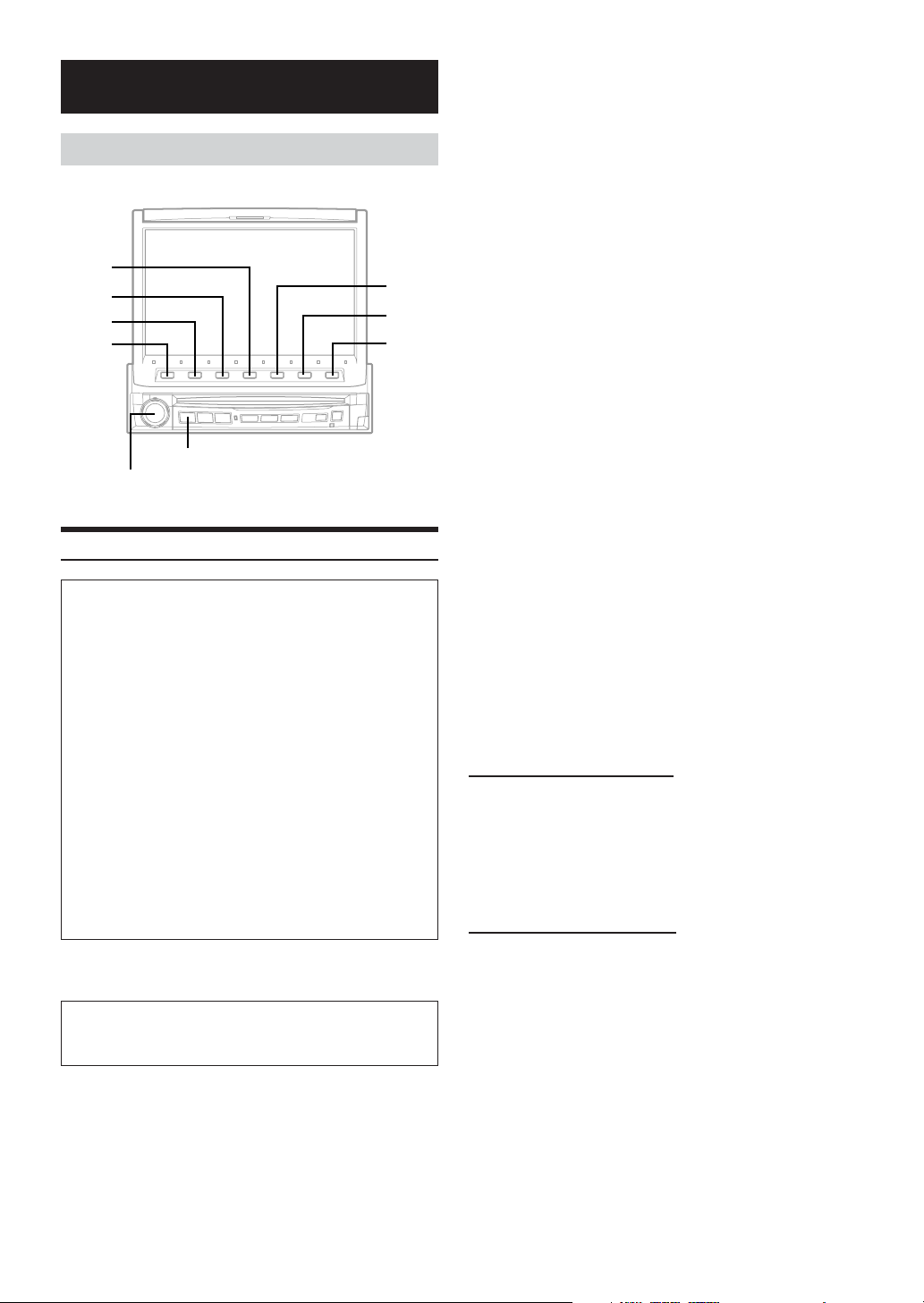
Setup
DVD Setup
4
3
2
1
Turn the Rotary encoder to select your desired
4
setting item.
The screen shows the ∗Function Guide.
*Displays the function assigned for each button (the Function
buttons).
Setting items:
MENU LANGUAGE ↔ AUDIO LANGUAGE ↔
SUB T. LANGUAGE ↔ COUNTRY CODE ↔ PARENTAL ↔
DIGITAL OUT MODE ↔ OPT. OUT ↔ TV SCREEN
Press the Function buttons to switch the setting.
5
Press 7 (RETURN).
5
6
7
6
The screen returns to the previous one.
•With the DVD screen displayed, pressing and rotating the rotary
encoder will adjust the volume level.
•Immediately after inputting titles or changing the settings of DVD
mode (while the system is inputting the titles or data automatically)
do not turn the ignition key (engine key) to OFF.
Otherwise, a title may not be written, or the settings may not be
changed.
SOURCE/POWER
Rotary encoder
DVD Setup Operation
To display the DVD mode screen:
To watch a video source, your vehicle must be parked with
the ignition key in the ACC or ON position. To do this, follow
the procedure below.
1. Bring your vehicle to a complete stop at a safe
location. Engage the parking brake.
2. Keep pushing the foot brake and release the parking
brake once then engage it again.
3. When the parking brake is engaged for the second
time, release the foot brake.
•For automatic transmission vehicles, place the transmission
lever in the Park position.
Now, the locking system for the DVD mode operation has
been released. Engaging the parking brake can reactivate
the DVD mode, as long as the car's ignition has not been
turned off. It is not necessary to repeat the above
procedure (1 through 3), of “To display the DVD mode
screen.”
Each time the ignition is turned OFF, perform the procedure
of “To display the DVD mode screen.”
Before setup operation below, select the DVD PLAYER mode.
If a disc is inserted into this unit, make sure to take it out.
The following steps 1 to 6 are common operations to each
“Setting item” of DVD Setup. Refer to each section for
details.
Changing the language setting
The audio language, subtitle language and menu language can be set
according to your preferences.
Once set, this becomes the default language. This function is
convenient when you always want to listen in English. (The language
setting is not effective on some discs. If not, the default language is
set from the factory.)
• When the settings are changed, the old settings are
overwritten. Make a note of the current settings
before making changes. The settings are not cleared
even when the vehicle’s battery is disconnected.
•To temporarily change the language of the current
disc, either do so from the DVD menu or by using the
operation described in the section “Switching
the audio tracks” (page 18).
• If the disc does not include the selected language, the disc’s default
language is set.
Setting of the Menu Language
Setting item: MENU LANGUAGE
Setting contents: AUTO / ENGLISH / GERMAN/FRENCH /
JAPAN / CODE
Set the language used for the menus (title menu, etc.).
• When “AUTO” is selected, the primary menu language among the
recorded ones is played.
Setting of the Audio Language
Setting item: AUDIO LANGUAGE
Setting contents: AUTO/ ENGLISH / GERMAN / FRENCH /
JAPAN / CODE
Set the audio language produced from the speakers.
• When “AUTO” is selected, the primary audio language among the
recorded ones is played.
1 Press SOURCE/POWER.
The main menu is displayed.
Press 6 (SETUP).
2
The Setup mode screen appears.
Turn the Rotary encoder to select “DVD,” then
3
press the Rotary encoder.
The DVD list is displayed.
28-EN
Page 31

Setting of the Subtitle Language
Setting item: SUB T. LANGUAGE
Setting contents: AUTO / ENGLISH / GERMAN / FRENCH /
JAPAN / CODE
Set the language of the subtitles displayed on the screen.
• When “AUTO” is selected, the primary subtitle language among
the recorded ones is played.
To play in a language other than those displayed
1Press 6 (CODE) of the Function buttons.
Number input box is displayed.
2Turn the Rotary encoder to input the first digit of the
language number.
As for the language number, refer to “List of language
codes” (page 59).
3Press the Rotary encoder to enter the first digit
number.
4 Repeat steps 2 and 3 to input a 4 digit language
number, then press 6 (ENTER) to memorize the
number.
Changing the Country Code Setting
Setting item: COUNTRY CODE
Setting content: CODE
Set the country code when setting the rating level (Parental lock).
• When the settings are changed, the old settings are overwritten.
Make a note of the current settings before making changes. The
settings are not cleared even when the vehicle’s battery is
disconnected.
1Press 6 (CODE) .
Number input box is displayed.
2Turn the Rotary encoder to input the first digit of the
country number.
As for the country number, refer to “List of Country
Codes” (page 60).
3Press the Rotary encoder to enter the first digit.
4 Repeat steps 2 and 3 to input a 4 digit country code,
then press 6 (ENTER) to memorize the code.
1Press 1 (P-WORD).
Number input box is displayed.
2Press 0 to 9 on the supplied remote control to input the
password.
The initial number is 1111.
Input a 4 digit pass word.
Input numbers are displayed as “∗”.
3Press 1 (ENTER) to memorize the number.
The PARENTAL screen appears.
Set the rating level of PARENTAL
4Turn the Rotary encoder to select PARENTAL LEVEL.
5Press 1 (;DN) or 2 (UP :) to select the rating level
(1 to 8).
Select “8” to cancel the parental lock or if you do not
want to set a rating level. The smaller the number, the
higher the rating level.
6Press 7 (RETURN) to return to the previous screen.
Changing the password
4Turn the Rotary encoder to select PASSWORD
CHANGE.
5Press 1 (P-WORD).
6Turn the Rotary encoder to input numbers, then press
the Rotary encoder to enter a new 4 digit pass word.
•Keep a note of the number somewhere safe in case you should
forget it.
7Press 1 (ENTER) to memorize the number.
8Press 7 (RETURN) to return the previous screen.
Changing the rating level temporarily
Some discs may request that you change the rating level set
in the default settings during playback. In this case, the
message appears on the monitor screen “PARENTAL LEVEL
CHANGE OK? <YES/NO>.”
If this screen appears, change the level as follows:
• To change parental level and play, press 2 (
• To play without changing the parental level, press 4 (L).
(When 4 (L) is pressed, playback will be at the parental
level set with “Setting the Rating Level (Parental Lock)” )
::
:/
::
JJ
J).
JJ
Setting the Rating Level (Parental Lock)
Setting item: PARENTAL
Setting content: P-WORD
Use this function to restrict the viewing of movies to children of
appropriate age levels only.
• When the settings are changed, the old settings are overwritten.
Make a note of the current settings before making changes. Then
settings are not cleared even when the vehicle’s battery is
disconnected.
• On unrated DVDs, playback will not be restricted even if the rating
level is set.
• Once set, this rating level remains in memory until changed. To
enable playback of discs of higher rating levels or to cancel the
parental lock, the setting must be changed.
• Not all DVDs provide a Parental Lock feature. If you are unsure
about a DVD, play it first to confirm. Do not leave DVDs
accessible to young children for whom you deem them
inappropriate.
Continued
29-EN
Page 32
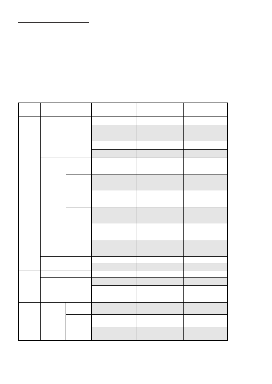
Changing the Digital Output Setting
Use the following procedure to set the digital audio signal output from
the IVA-D901.
Setting item: DIGITAL OUT MODE
Setting contents: AUTO / LPCM
AUTO: The digital output is switched automatically according
to the type of audio signals being played.
Be sure to select “AUTO” when you want to connect a
digital audio processor and play Dolby Digital audio.
“AUTO” is the factory setting.
LPCM: The audio signals recorded on the disc are converted
to 48 kHz/16 bit (for DVDs) or 44.1 kHz (for video CDs
and CDs) linear PCM audio signals for output.
Audio output/Optical digital audio output
Disc Audio recording
format
DVD
Dolby Digital
Linear PCM
MPEG2
Video CD
CD
MP3
MPEG
Audio
Layer3
Bit Rate:
32kbps
320kbps
MPEG1
Linear PCM
~
DTS
48kHz/16bit
48kHz/20bit
48kHz/24bit
96kHz/16bit
96kHz/20bit
96kHz/24bit
DTS
32kHz/16bit
44.1kHz/16bit
48kHz/16bit
Digital output
setting
AUTO
LPCM
AUTO
LPCM
AUTO
or
LPCM
AUTO
or
LPCM
AUTO
or
LPCM
AUTO
or
LPCM
AUTO
or
LPCM
AUTO
or
LPCM
AUTO or LPCM
AUTO or LPCM
AUTO or LPCM
AUTO
LPCM
AUTO or LPCM
AUTO or LPCM
AUTO or LPCM
Optical digital audio output
(when a digital audio
processor is connected)
DTS Elementary Stream
LPCM Encode
2ch Down mix
(48kHz/16bit)
Dolby Digital
LPCM (48kHz/16bit)
LPCM (48kHz/16bit)
LPCM (48kHz/16bit)
LPCM (48kHz/16bit)
LPCM (48kHz/16bit)
LPCM (48kHz/16bit)
LPCM (48kHz/16bit)
LPCM (48kHz/16bit)
LPCM (44.1kHz)
LPCM (44.1kHz)
DTS Elementary Stream
LPCM Encode
2ch Down mix
(44.1kHz/16bit)
LPCM Encode
2ch
(32kHz/16bit)
LPCM Encode
2ch
(44.1kHz/16bit)
LPCM Encode
2ch
(48kHz/16bit)
Analog audio
output (Ai-NET,
RCA output)
OK
OK
OK
OK
OK
OK
OK
OK
OK
OK
OK
OK
OK
OK
OK
OK
OK
OK
30-EN
Page 33
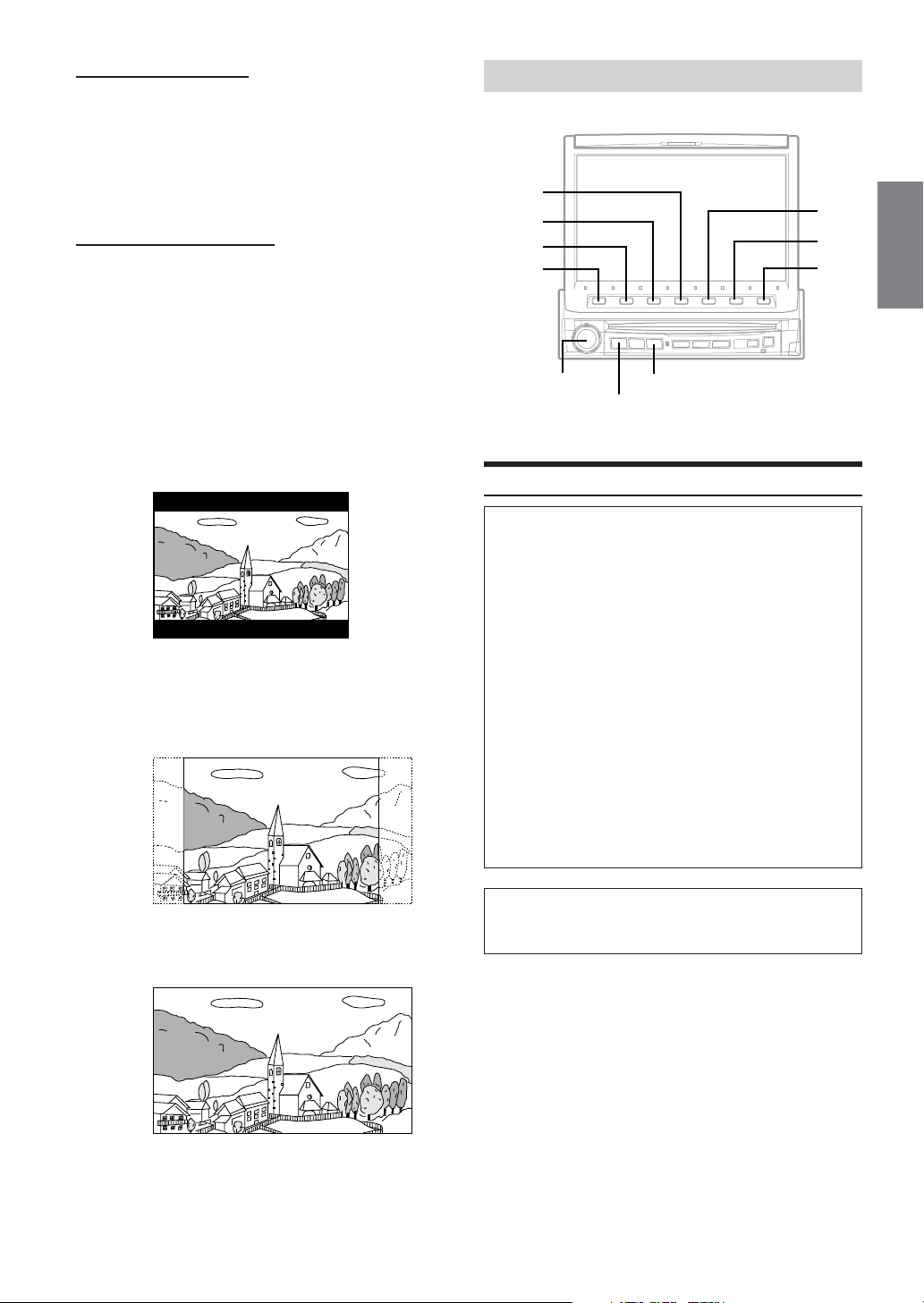
Setting the Digital Output
To connect an audio processor using the optical digital output, set to
“ON” by the following procedure.
Setting item: OPT.OUT
Setting contents: OFF / ON
•Afterwards, set ACC to OFF once, then turn it ON again. The
setting of Digital Output is decided.
Setting the TV Screen Setting
Use the procedure described below to set the output screen according
to the type of TV monitor (rear monitor) being used.
Setting item: TV SCREEN
Setting contents: 4:3 LB / 4:3 PS/ 16:9
•For some discs, the picture may not be set to the selected screen
size. (For details, refer to the explanation on the disc’s jacket.)
4:3 LB:
Select this when connected to a conventional 4:3 size (normal
TV aspect ratio) monitor. There may be black stripes visible at
the top and bottom of the screen (when playing a 16 : 9 size
movie). The width of these stripes will depend upon the
original aspect ratio of the theatrical release of the movie.
4:3 PS:
Select this when connected to a conventional 4:3 size monitor.
The picture will fill the entire TV screen. However, due to the
mismatch in aspect ratio, parts of the movie at the extreme left
and right sides will not be visible (when playing a
16 : 9 size movie).
GENERAL Setup
4
3
2
1
Rotary encoder
SOURCE/POWER
General Setup Operation
To display the General mode screen:
To watch a video source, your vehicle must be parked with
the ignition key in the ACC or ON position. To do this, follow
the procedure below.
1. Bring your vehicle to a complete stop at a safe
location. Engage the parking brake.
2. Keep pushing the foot brake and release the parking
brake once then engage it again.
3. When the parking brake is engaged for the second
time, release the foot brake.
•For automatic transmission vehicles, place the
transmission lever in the Park position.
Now, the locking system for the General mode operation
has been released. Engaging the parking brake can
reactivate the General mode, as long as the car's ignition
has not been turned off. It is not necessary to repeat the
above procedure (1 through 3), of “To display the General
mode screen.”
Each time the ignition is turned OFF, perform the procedure
of “To display the General mode screen.”
V.SEL
5
6
7
16:9:
Select this when connected to a wide screen TV. This is the
factory setting.
The following steps 1 to 6 are common operations to each
“Setting item” of GENERAL Setup. Refer to each section for
details.
1 Press SOURCE/POWER.
The main menu is displayed.
Press 6 (SETUP).
2
The Setup mode screen appears.
Turn the Rotary encoder to select “GENERAL,”
3
then press the Rotary encoder.
The GENERAL list is displayed.
Continued
31-EN
Page 34
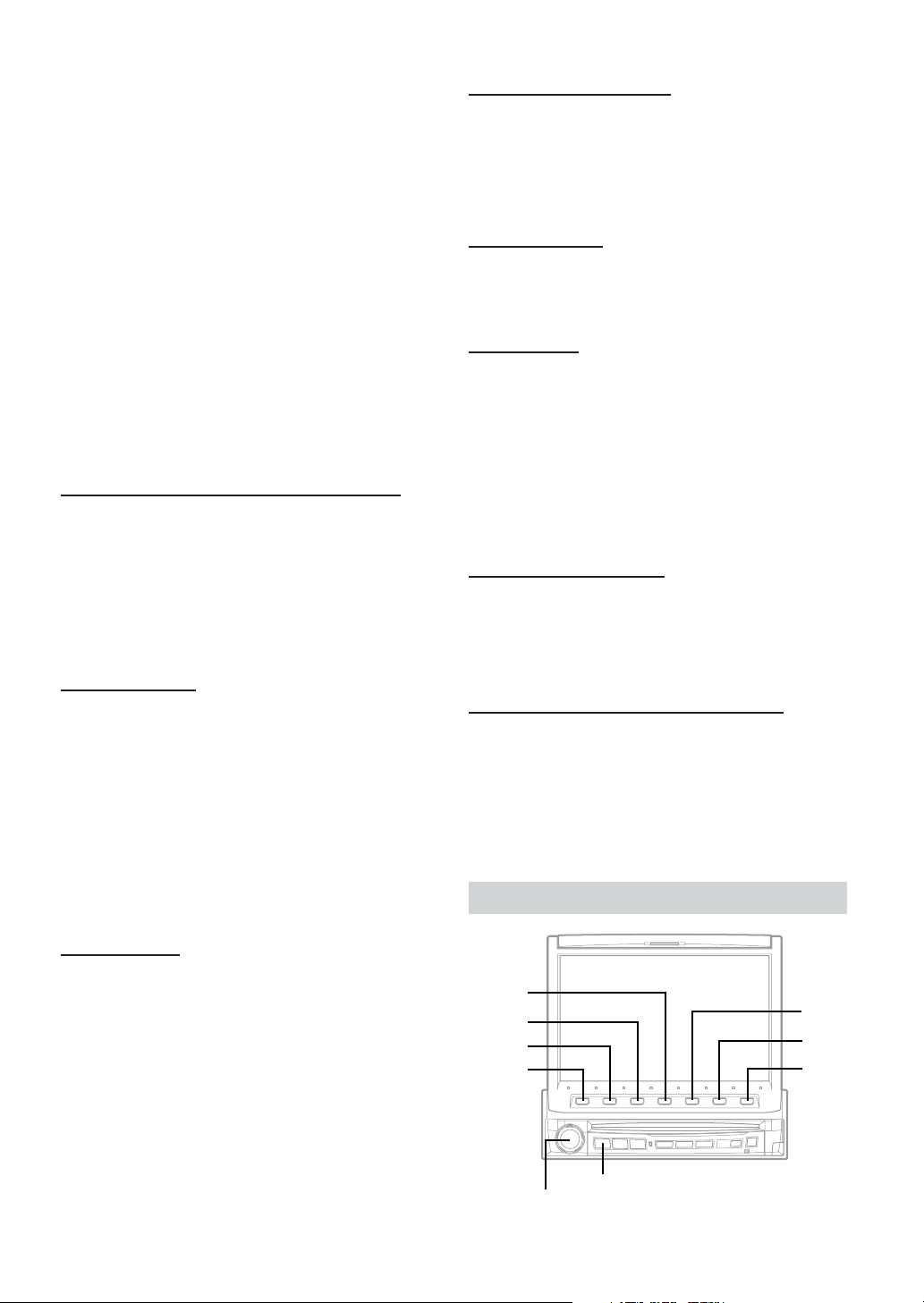
Turn the Rotary encoder to select your desired
4
setting item.
The screen shows the ∗Function Guide.
*Displays the function assigned for each button (the Function
buttons).
Setting items:
MONITOR OPEN/CLOSE ↔ V.SEL KEY ↔ MULTI
SESSION PLAY ↔ BEEP ↔ CLOCK ↔ CLOCK ADJUST
↔ DAYLIGHT SAVING TIME ↔ ∗PHONE RECEIVE
*Displayed only when Mobile Hub (CXA-B200NK) is
connected.
Press the Function buttons to switch the setting.
5
Press 7 (RETURN).
6
The screen returns to the previous one.
•With the General screen displayed, pressing and rotating the rotary
encoder can adjust the volume level.
•Immediately after inputting titles or changing the settings of
General Mode (While the system is inputting the titles or data
automatically) do not turn the ignition key (engine key) to OFF.
Otherwise, the title may not be written, or the settings may not be
changed.
Setting Automatic Opening/Closing of the Monitor
Setting item: MONITOR OPEN / CLOSE
Setting content: MANUAL / FULL / CLOSE
MANUAL: The monitor is manually opened or closed by
FULL: The monitor automatically opens or closes when
CLOSE: The monitor automatically closes when the ignition
pressing OPEN/CLOSE.
the ignition key is turned to the "ACC" or "ON"
position.
key is turned OFF.
Setting Visual Mode
Setting item: V.SEL KEY
Setting content: NAV. / V.SEL
You can display the screen of the preset item by just pressing the
V. SEL button on the IVA-D901.
NAV.: Pressing V.SEL directly switches to the navigation
screen.
V. SEL:Each press of V. SEL switches the modes:
<ex.>
SOURCE DISPLAY → AUX1 → AUX2 → AUX3
→ Navigation → CAMERA → SOURCE DISPLAY
• This operation cannot be carried out when NAV. IN, CAMERA IN
and AUX IN 1 to 3 in the SYSTEM list screen are set to off.
Sound (Beep) Guide Function
Setting item: BEEP
Setting content: OFF / ON
ON: Activate the Sound Guide mode.
OFF: Deactivate the Sound Guide mode. The sound guide
beep will not be produced when a button on the unit is
pressed.
Displaying the Time
Setting item: CLOCK
Setting content: OFF / ON
The clock display is turned off or on respectively.
Setting the Time
Setting item: CLOCK ADJUST
Setting content: HOUR DN / UP / MINUTE DN / UP / TIME RESET
HOUR DN / UP: Adjust the hour.
MINUTE DN / UP: Adjust the minute.
TIME RESET: When it is pressed at “:less than 30,” the
minute will be “:00”; at “: more than 30,”
the hour advances.
• The clock adjusting mode is canceled when the power is turned off,
when 7 (RETURN) is pressed, or when another item of
GENERAL SETUP is selected.
Setting Daylight Saving Time
Setting item: DAYLIGHT SAVING TIME
Setting content: OFF / ON
ON: Place the Summer Time mode ON. The time advances
by one hour.
OFF: Return to the ordinary time.
Switching the Incoming Calls of the Telephone
Setting item: PHONE RECEIVE
Setting content: AUTO / MANUAL
This operation can be carried out only when a cellular phone and
Mobile Hub (CXA-B200NK) is connected.
• The incoming call can be switched to Automatic Calling or Manual
Calling.
SYSTEM Setup
Playing MP3 Data
Setting item: MULTI SESSION PLAY
Setting content: CD / MP3
When using discs containing both audio data and MP3 data.
CD: Plays only the audio data on discs containing both audio
data and MP3 data.
MP3: Playes only the MP3 files on discs containing both audio
data and MP3 data.
• When an MP3 CD changer is used, both the audio data and the
MP3 data will be played.
32-EN
4
3
2
1
SOURCE/POWER
Rotary encoder
5
6
7
Page 35
System Setup Operation
To display the System mode screen:
To watch a video source, your vehicle must be parked with
the ignition key in the ACC or ON position. To do this, follow
the procedure below.
1. Brake to bring your vehicle to a complete stop at a
safe location. Engage the parking brake.
2. Keep pushing the foot brake and release the parking
brake once then engage it again.
3. When the parking brake is engaged for the second
time, release the foot brake.
•For automatic transmission vehicles, place the transmission
lever in the Park position.
Now, the locking system for the System mode operation has
been released. Engaging the parking brake can reactivate
the System mode, as long as the car's ignition has not been
turned off. It is not necessary to repeat the above
procedure (1 through 3), of “To display the System mode
screen.”
Each time the ignition is turned OFF, perform the procedure
of “To display the System mode screen.”
The following steps 1 to 6 are common operations to each
“Setting item” of SYSTEM Setup. Refer to each section for
details.
Press SOURCE/POWER.
1
The main menu is displayed.
Press 6 (SETUP).
2
The Setup mode screen appears.
Turn the Rotary encoder to select “SYSTEM,”
3
then press the Rotary encoder.
The SYSTEM list is displayed.
Turn the Rotary encoder to select your desired
4
setting item.
The screen shows the ∗Function Guide.
*Displays the function assigned for each button (the Function
buttons).
Setting items:
NAV.MIX ↔ NAV.IN ↔ AUX IN1 ↔ AUX IN2 ↔ AUX IN3
↔ AUX IN1 MODE ↔ AUX IN2 MODE ↔ AUX IN3 MODE
↔ CAMERA IN ↔ MONITOR OUT1 ↔ MONITOR OUT2
↔ IN-INT MUTE ↔ IN-INT ICON ↔ A.PROC TYPE
Press the function buttons to switch the setting.
5
Press 7 (RETURN).
6
The screen returns to the previous one.
•With the System screen displayed, pressing and rotating the rotary
encoder will adjust the volume level.
•Immediately after inputting titles or changing the settings of
System Mode (While the system is inputting the titles or data
automatically) do not turn the ignition key (engine key) to OFF.
Otherwise, a title may not be written, or the settings may not be
changed.
Navigation Interruption and Adjusting its Volume
Setting item: NAV.MIX
Setting content: OFF / ON
With an Alpine navigation system connected to the IVA-D901, the
voice guidance of the navigation system will be mixed with the radio
or CD play. You can adjust the volume level of the voice guidance.
OFF: The navigation interruption mode is turned off.
ON: The navigation interruption mode is on.
1) After setting it to ON, press the Rotary encoder to select
NAV.MIX mode.
VOL. → NAV. → SUB W. → BAL. → FAD. → DEFEAT →
VOL.
2) Turn the Rotary encoder to adjust the volume (0 to 15) of
the navigation voice.
• The audio volume during the navigation guide can be set by
adjusting the audio volume while the navigation guide continues.
When the navigation guide finishes, the previous audio volume and
the previous screen are restored. For exception, if the navigation
cuts in when the audio volume is lower than the setting level, the
audio volume during the navigation guide is reset the current
listening volume. (When the navigation guide cuts in, the audio
volume does not increase.)
• This setting is effective when NAV.IN of SYSTEM list screen is ON.
• When PXA-H510 or PXA-H900 is connected, NAV.MIX value set in
this unit does not affect PXA-H510 or PXA-H900.
Setting the Navigation Mode
When you connect an optional navigation equipment, set it to ON.
Setting item: NAV. IN
Setting contents: OFF / ON
ON: Navigation source is displayed.
OFF: Navigation source is not displayed. The settings
related to the navigation can not be changed from this
unit.
Setting the AUX Mode
Setting item: AUX IN 1, 2, 3
Setting content: OFF / LEVEL LOW / HIGH
OFF: AUX source is not displayed.
LEVEL LOW/HIGH:
The sound volume from the external equipment can be
adjusted. When LOW or HIGH is selected, AUX source
will be ON.
• OFF is not displayed when the optional DVD player or DVD
changer is connected.
• When OFF is selected, the settings related to AUX can not be
changed from this unit (except for “Name external equipment to be
displayed” page 34).
• When either DVD player or DVD changer is connected to AUX IN
1, DVD is displayed on the screen. When both of them are
connected, DVD is displayed for AUX IN 1 and DVD CHG is
displayed for AUX IN 2.
Continued
33-EN
Page 36
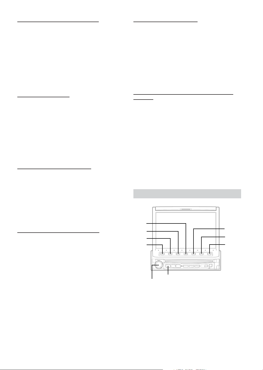
Name External Equipment to be Displayed
When more than one external device is connected, you can name each
(up to 3) as you like.
Setting items: AUX IN 1 to 3 MODE
Setting contents: AUX / VCR / GAME 1,2 / TV
• The selected source name is displayed instead of AUX source
name. When a source is selected, the Function Guide of AUX mode
appears.
• Only AUX IN 3 MODE can be named “TV.” When AUX mode is
selected, “TV” is displayed as the source name and the Function
Guide of TV mode appears.
• Only when an Alpine TV tuner is connected, can you operate the
displayed function guide from this unit.
Setting of the Rear Camera
When the rear camera is connected, rear pictures are output on the
screen.
Setting item: CAMERA IN
Setting contents: OFF/ON
ON: Even if the shift lever is not set to reverse (R), the rear
pictures are output by pressing V.SEL and selecting
the CAMERA source.
OFF: The rear pictures are not output.
• By shifting to reverse (R), the rear pictures are output.
This function is effective when the reverse wire is properly
connected.
Setting of the External Monitor Output
Set it to ON when you use the rear entertainment function (page 25).
Setting items: MONITOR OUT 1, 2
Setting contents: OFF / ON
ON: By setting the connected external monitor to ON, the
remote control will be usable.
OFF: When either MONITOR OUT 1 or 2 is set to OFF, only
one monitor can be set by the rear enter function.
When both MONITOR OUT 1 and 2 are set to OFF,
R.SEL in the Function Guide displayed in the main
menu cannot be used.
Setting the External Device Interrupt Mode
Setting item: IN-INT MUTE
Setting content: OFF / ON
If an Alpine Ai-NET Auxiliary Input Adapter (KCA-801B) is
connected to the IVA-D901, an Auxiliary Source will be allowed to
interrupt the current audio source. For example, you can listen to a
portable MP3 player through your car audio system even with a CD
changer connected and playing. The CD changer will automatically
mute when switched to the AUX Input. For further details on how to
use the Alpine KCA-801B, see your authorized Alpine dealer.
OFF: The volume level can be adjusted in Interrupt mode.
ON: Sound will not be output.
• The auxiliary device being connected must have an Interrupt wire
with a negative trigger for this function to operate automatically.
Otherwise, a separate switch needs to be added to switch it
manually.
Setting the Interrupt Icon Display
Setting item: IN-INT ICON
Setting content: INT / TEL
The unit can display the icon of an external device, such as a
telephone, whenever a phone call comes in to tell you there is a phone
call.
INT: The INT icon appears on the display.
TEL: When the external device (telephone) sends the
interrupt signal, the telephone icon appears on the
display.
• TEL icon on this setting is not related to TEL Link Operation
(pages 40 - 43).
Optical Digital Input Selection for an External Audio
Processor
Make sure “OPT.OUT” is ON in “Setting the Digital Output” (page
31) before switching this setting.
Setting item: A.PROC TYPE
Setting contents: PXA-H510 / OTHER
OTHER:
When connecting any audio processor via an optical
digital cable except the PXA-H510.
Connect the optical digital input connector with the
connector for the Head unit.
PXA-H510:
When connecting PXA-H510.
Connect the optical digital input connector with the
connector for the DVD.
•Afterwards, set ACC to OFF once, then turn it ON again. The
setting of optical digital input switch is decided.
DISPLAY Setup
4
3
2
1
SOURCE/POWER
Rotary encoder
5
6
7
34-EN
Page 37
Display Setup Operation
To display the Display mode screen:
To watch a video source, your vehicle must be parked with
the ignition key in the ACC or ON position. To do this, follow
the procedure below.
1. Bring your vehicle to a complete stop at a safe
location. Engage the parking brake.
2. Keep pushing the foot brake and release the parking
brake once then engage it again.
3. When the parking brake is engaged for the second
time, release the foot brake.
•For automatic transmission vehicles, place the transmission
lever in the Park position.
Now, the locking system for the Display mode operation has
been released. Engaging the parking brake can reactivate
the Display mode, as long as the car's ignition has not been
turned off. It is not necessary to repeat the above procedure
(1 through 3), of “To display the Display mode screen.”
Each time the ignition is turned OFF, perform the procedure
of “To display the Display mode screen.”
The following steps 1 to 6 are common operations to each
“Setting item” of DISPLAY Setup. Refer to each section for
details.
Press SOURCE/POWER.
1
The main menu is displayed.
Press 6 (SETUP).
2
The Setup mode screen appears.
Turn the Rotary encoder to select “DISPLAY,”
3
then press the Rotary encoder.
The DISPLAY list is displayed.
Turn the Rotary encoder to select your desired
4
setting item.
The screen shows the ∗Function Guide.
*Displays the function assigned for each button (the Function
buttons).
Setting items:
DIMMER ↔ BRIGHT ↔ TINT ↔ COLOR ↔ BACK GND
↔ AUTO BACK GND
Press the function buttons to switch the setting.
5
Press 7 (RETURN).
6
The screen returns to the previous one.
•With the Display screen displayed, pressing and rotating the rotary
encoder can adjust the volume level.
•Immediately after inputting titles or changing the settings of
Display Mode (While the system is inputting the titles or data
automatically) do not turn the ignition key (engine key) to OFF.
Otherwise, a title may not be written, or the settings may not be
changed.
Illumination Control
Setting item: DIMMER
Setting content: OFF / ON / AUTO
The back light (fluorescent light) built in the liquid crystal panel is
switched to the brightness of the car inside to be easy to be seen.
OFF: Deactivate Auto Dimmer mode to keep the
background illumination of the monitor bright.
ON: Keep the background illumination of the monitor dark.
AUTO: Adjust the brightness of the background illumination
of the monitor automatically to the brightness of the
car inside.
Adjusting Brightness
Setting item: BRIGHT
Setting content: DARK / ±0 / LIGHT
DARK / LIGHT:
Press 1 (; DARK) to make the picture darker or press
3 (LIGHT :) to make the picture brighter. You can
adjust the brightness between MIN (–15) and MAX
(+15). When it reaches the minimum or maximum point,
the display shows "MIN" or "MAX" respectively.
±0: To quickly set to the center position, press 2 (±0).
Adjusting Tint of Picture
Setting item: TINT
Setting content: GRN. / ±0 / RED
Tint adjustment can be made only in the navigation, DVD, AUX1,
AUX2 and AUX3 modes.
Tint adjustment cannot be made if a Navigation system with the RGB
feature is connected.
GRN / RED: Press 1 (; GRN) to adjust green and press
3 (RED :) to adjust red.
Adjust the color from G15 to R15. “G MAX” or “R MAX” is
displayed at the maximum of each color.
±0: To quickly set to the center position, press 2 (±0).
Adjusting Color of Picture
Setting item: COLOR
Setting content: THIN / ±0 / THICK
Color adjustment can be made only in the navigation, DVD, AUX1,
AUX2 and AUX3 modes.
Color adjustment cannot be made if a Navigation system with the
RGB feature is connected.
THIN / THICK:
Press 1 (; THIN) or 3 (THICK :) to make the color of
the picture brighter or darker respectively to get your
desired color. You can adjust the color between MIN (–
15) and MAX (+15). When it reaches the minimum or
maximum point, the display shows "MIN" or "MAX"
respectively.
±0: To quickly set to the center position, press 2 (±0).
Switching Background Textures
Setting item: BACK GND
Setting content: MODE1(LIGHT) / MODE2(WATER) /
MODE3(WOOD) / MODE4(SKY) / MODE5(TIME) / MODE6(WIREFRAME)
You have a choice of 6 different background textures preset at the
factory. Select them following the procedure below.
Setting Automatic Background Textures
Setting item: AUTO BACK GND
Setting content: OFF / ON
Turn on the Automatic Background Texture Scroll to automatically
change background texture. The background texture will change each
time the ignition key is turned off and turned back on again (6 textures).
ON: Tu rn on the Auto Background Texture Scroll mode.
The background textures will scroll when the ignition key
is turned off once and turned back on again as follows:
LIGHT → WATER → WOOD → SKY → TIME →
WIRE-FRAME → LIGHT
OFF: Tu rn off the Auto Background Texture Scroll mode.
35-EN
Page 38
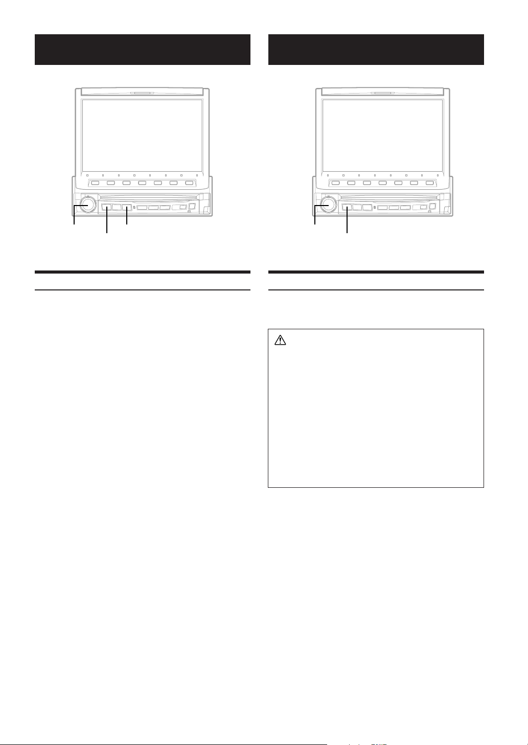
Navigation System (Optional)
Auxiliary Device (Optional)
Rotary encoder
SOURCE/POWER
V.SEL
Controlling the Navigation System (Optional)
If an optional Alpine Navigation System is connected to the IVAD901, some of its functions can be controlled from the IVA-D901.
Press SOURCE/POWER.
1
The main menu screen appears on the display.
Turn the Rotary encoder and select "NAV.", then
2
press the Rotary encoder to execute the
selection.
The Function Guide display changes to show the same
button names as those for the remote control supplied.
• When V. SEL is pressed while the Navigation selection mode is
being selected in “Setting Visual Mode” (refer to page 32), the
navigation mode will be directly activated.
• If the Navigation mode menu is not displayed on the main menu
screen, set NAV. IN to on by following "Setting the navigation
mode" (page 33).
• If you use the buttons displayed, you can control the navigation
system from IVA-D901 in the similar way to the remote control
operation.
Fo r operation, refer to the Owner's Manual for your navigation
system.
• Depending on the navigation system connected to this unit, some
functions and displays may vary.
• When the Navigation System is on, the audio and visual navigation
cuts in.
Rotary encoder
SOURCE/POWER
Operating Auxiliary Devices (Optional)
To operate your devices connected to the AUX terminals on the rear
panel of IVA-D901, follow the procedure described below.
WARN ING
It is dangerous (and illegal in many states) for the driver to
watch the TV/Video while driving the vehicle. The driver
may be distracted from looking ahead and an accident
could occur.
Install the IVA-D901 correctly so that the driver cannot
watch TV/Video unless the vehicle is stopped and the
emergency brake is applied.
If the IVA-D901 is not installed correctly, the driver will be
able to watch the TV/Video while driving the vehicle and
may be distracted from looking ahead and cause an
accident. The driver or other people could be severely
injured.
36-EN
Page 39
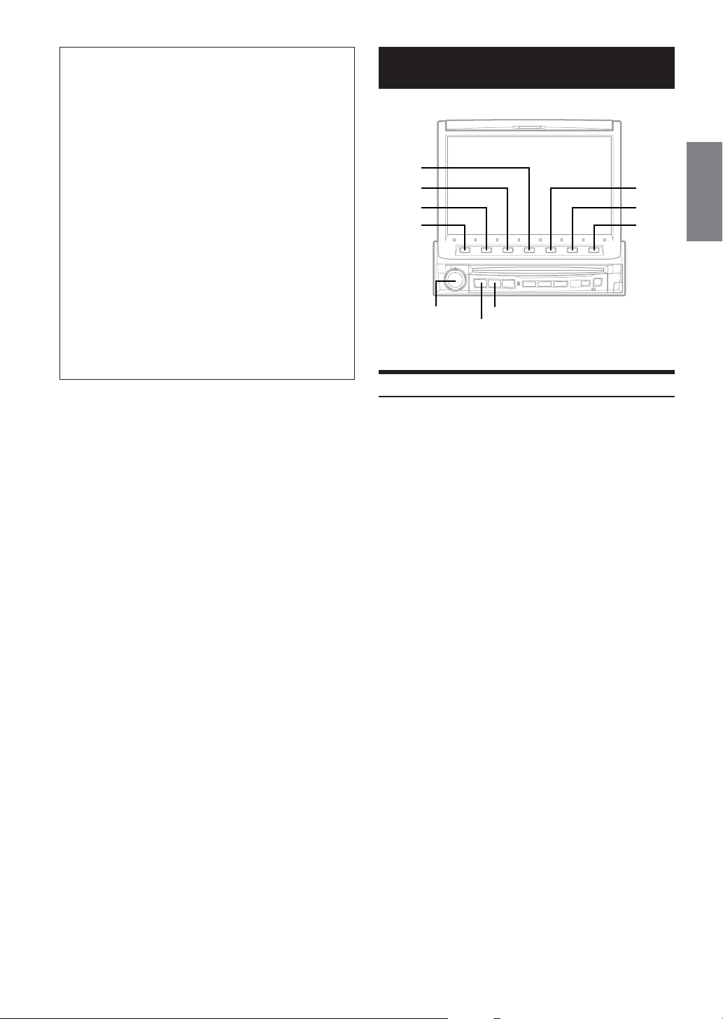
To activate your auxiliary devices:
To watch a video source, your vehicle must be parked with
the ignition key in the ACC or ON position. To do this, follow
the procedure below.
1. Bring your vehicle to a complete stop at a safe
location. Engage the parking brake.
2. Keep pushing the foot brake and release the parking
brake once then engage it again.
3. When the parking brake is engaged for the second
time, release the foot brake.
•For automatic transmission vehicles, place the transmission
lever in the Park position.
Now, the locking system for the AUX mode operation has
been released. Engaging the parking brake can reactivate
the AUX mode, as long as the car's ignition has not been
turned off. It is not necessary to repeat the above
procedure (1 through 3), of “To activate your auxiliary
devices.”
Each time the ignition is turned OFF, perform the procedure
of “To activate your auxiliary devices.”
• If you try to activate the auxiliary device while driving, the
display will show the warning-PICTURE OFF FOR YOUR
SAFETY.
Press SOURCE/POWER.
1
The main menu screen appears on the display.
Turn the Rotary encoder and select “AUX,” then
2
press the Rotary encoder to execute the
selection.
• If the AUX mode is not displayed on the main menu, set AUX IN to
LEVEL LOW or HIGH by following "Setting the AUX mode" (page
33).
Changer (Optional)
4
3
2
1
Rotary encoder
SOURCE/POWER
BAND
Controlling CD Changer (Optional)
An optional 6-disc or 12-disc CD Changer may be connected to the
IVA-D901 if it is Ai-NET compatible. With a CD Changer connected
to the Ai-NET input of the IVA-D901, the CD Changer will be
controllable from the IVA-D901.
If you connect a changer compatible with MP3, you can play CD-
ROMs, CD-Rs, and CD-RWs containing MP3 files on the IVA-D901.
Using the KCA-400C (the Multi-Changer Switching device) multiple
changers can be controlled by the IVA-D901.
See the Multi-Changer Selection section for selecting the CD
Changers (page 38).
Press SOURCE/POWER to display the main
1
menu.
Turn the Rotary encoder to select "CD CHG,"
2
then press the Rotary encoder.
The display changes to the CD changer mode screen.
When a 6 Disc CD Changer is connected;
3
1Press 7 (PAGE 1/2).
The Function Guide display changes.
2Press the Function buttons to select your desired disc
loaded.
The Function buttons 1 (DISC1) through 6 (DISC6)
select the discs from the first disc to 6th disc.
When an MP3 compatible CD changer is connected;
1Press 7 (PAGE 1/3) twice to change the Function
Guide display.
2Press the Function buttons to select your desired disc
among the loaded ones.
The Function buttons 1 (DISC1) through 6 (DISC6)
select the discs from the first disc to 6th disc.
5
6
7
Continued
37-EN
Page 40
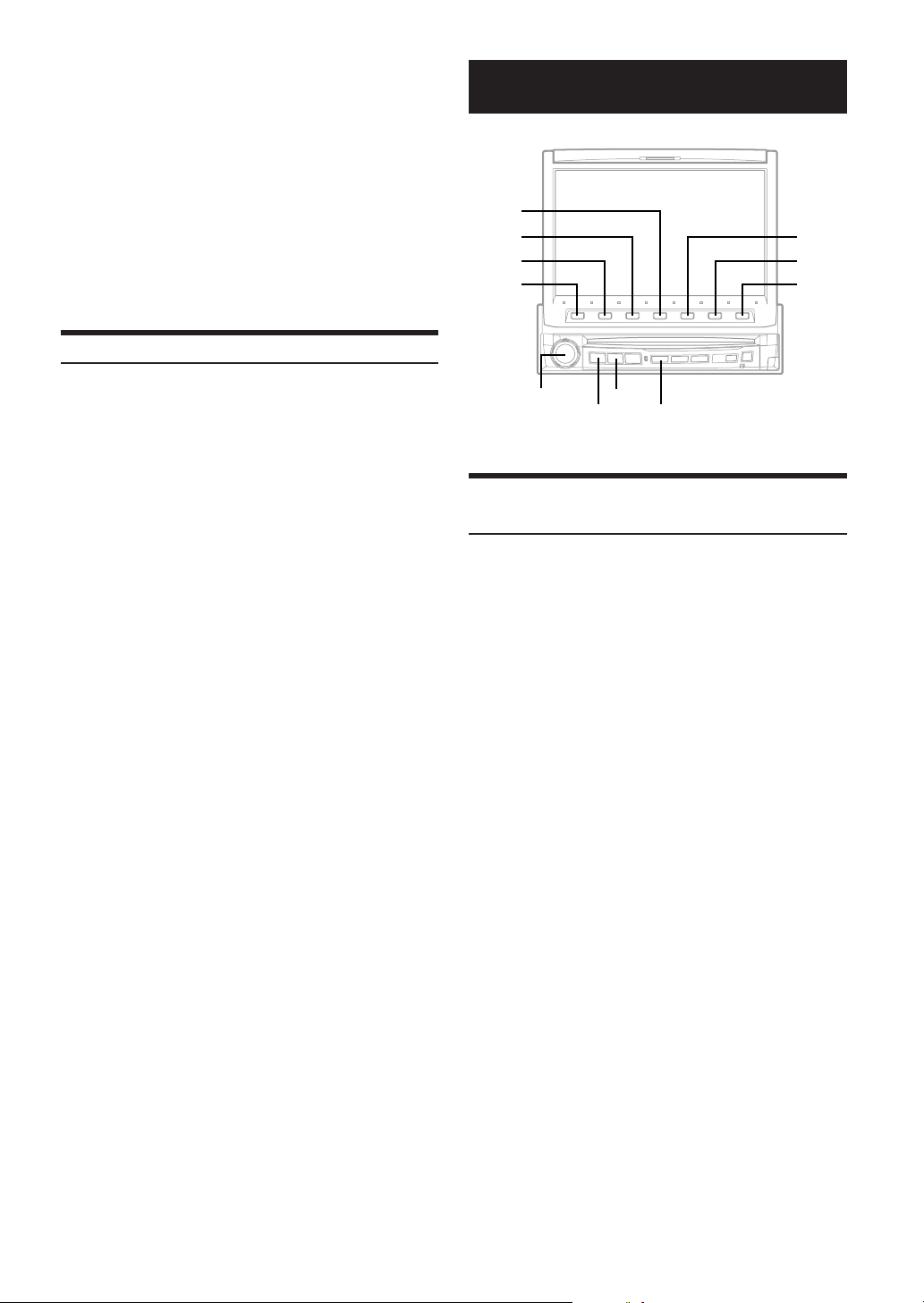
When a 12-Disc CD Changer is connected;
You can select the disc numbers 1 to 6 in the same manner as
for 6-disc Changer.
Press 7 (PAGE 1/3) twice to select the disc numbers 7
to 12.
The Function Guide display changes and now the
Function buttons 1-6 represent disc numbers 7-12.
•After selecting the desired disc, you can operate in the same way as
for the CD player. For details, see the CD/MP3 section.
•Press BAND to switch the Disc mode in the CD/DVD/Changer
mode.
• When an MP3 compatible CD changer is connected, the unit can
play discs containing both audio data and MP3 data.
• The DVD changer (optional) is controllable from the IVA-D901 as
well as the CD changer.
Multi-Changer Selection (Optional)
XM Radio (Optional)
4
3
2
1
5
6
7
Alpine's Ai-NET system will support up to 6 CD Changers. When
operating two or more changers, the KCA-400C (Multi-Changer
Switching device) must be used. If you use 1 Switching device, you
can connect up to 4 CD Changers. If you use 2 Switching devices,
you can connect up to 6 CD Changers. When using KCA-410C
(Versatile Link Terminal), you can connect two changers only.
Press SOURCE/POWER to display the main
1
menu.
Turn the Rotary encoder to select a desired
2
changer.
The display shows the selected CD changer mode
screen.
• When one KCA-400C is connected to the changer, "Changer
1-4" is displayed in the main menu. When two KCA-400Cs
are connected to the changer, "Changer 1-6" is displayed in
the main menu. When one KCA-410C is connected to the
changer, "Changer 1-2" is displayed in the main menu.
•In Changer mode, you can select the next changer (connected
changers only) by pressing BAND on the unit or on the
remote.
•You cannot operate this function in the Title display or Title
Inputting display.
To operate the selected changer, see "CD/MP3"
3
section.
•To operate the selected changer, see “CD/MP3”(pages 12-
13).
Rotary encoder
SOURCE/POWER
BAND
LIST/INPUT
Receiving XM Channels with the XM
Receiver (Optional)
XM Satellite Radio* is the next generation of audio entertainment,
with up to 100 brand-new digital channels. For a small monthly fee,
subscribers can hear crystal-clear music, sports, news and talk, coastto-coast via satellite. For more information, visit XM’s website at
www.xmradio.com or call 1-800-852-9696.
An optional XM Satellite Radio Receiver (TUA-T021XM) and an
optional XM Antenna may be connected to the IVA-D901. With an
XM Receiver connected to the Ai-NET input of the IVA-D901, the
XM Receiver will be controllable from the IVA-D901.
* XM and its corresponding logos are trademarks of XM
Satellite Radio Inc.
• The controls on the IVA-D901 for XM Receiver operation are
operative only when an XM Receiver is connected.
Press SOURCE/POWER.
1
The main menu is displayed.
Turn the Rotary encoder to select “XM,” then
2
press the Rotary encoder.
Press BAND to select XM1, XM2 or XM3.
3
Press 2 (NO./NAME) to select the channel
4
number tuning.
Each time it is pressed, the tuning mode is changed.
channel number tuning ↔ channel name tuning
Press 1 (; CH NO. DN) or 3 (CH NO. UP :) to
5
select the desired channel. Holding either button
down will change channels continuously.
When you select the channel name tuning in step 4, press
1 (; CH NAME DN) or 3 (CH NAME UP :) to select a
channel name.
38-EN
Page 41
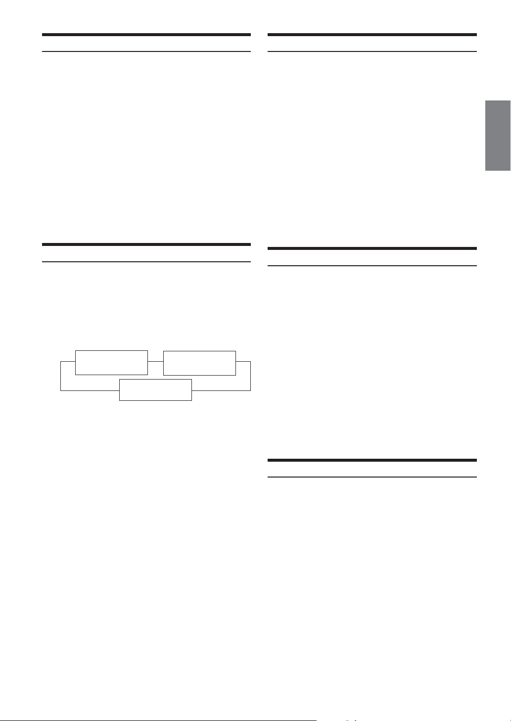
Tuning in to Categorized Programs
Checking the XM Radio ID Number
You can listen to programs categorized to the same group one after
another.
In XM mode, press 4 (CAT).
1
The category of the current program is displayed.
Press 2(CH/CAT) to select the category tuning.
2
Each time it is pressed, the tuning mode is changed.
Channel number tuning ↔ Category tuning
While the category name is displayed, press 1
3
(;CAT DN) or 3 (CAT UP :) to select a desired
category.
The selected category is tuned.
• When you select Channel number tuning in step 2, press the
1 (;CH DN) or 3 (CH UP :) button to select a channel
number.
• If the desired category program is not found, the selected category
is displayed for 5 seconds, then the receiving program is restored.
Changing the Display
Text information, such as the channel name, artist name/feature, and
song/program title, is available with each XM channel. The unit can
display this text information as explained below.
In XM mode, press 5 (TITLE).
Each time you press this button, the display changes as shown
below.
Channel name/ Title name/
--
Category display Artist name display
Information display
*1Channel number, category, title name, etc., are displayed in
one screen.
• By pressing 5 (TITLE) for more than 2 seconds during each
display mode above, the Auxiliary Data Field appears.
/
1
*
You need to provide XM with the unique XM Radio ID number for
your XM Radio Receiver in order to subscribe to XM's programming.
This number is an 8 character alphanumeric number that is printed on
a label directly on the XM Receiver.
It can also be displayed on the screen of the IVA-D901 in the
following way.
While receiving XM1/XM2 or XM3, press 1 (; CH
1
NO. DN) or 3 (CH NO. UP :) to select channel
“0.”
The unit displays the ID number.
2
To cancel the ID number display, set the channel to
3
other than “0.”
•You cannot use “O,” “S,” “ I,” or “F” for the ID Number.
•You can check your ID number printed on the label on the package
of your XM Satellite Radio Receiver (TUA-T021XM).
Storing XM Channel Presets
Press BAND to select the desired band (XM1,XM2
1
or XM3) you want to store.
Press 7 (PAGE 1/2).
2
The Function Guide is switched.
After tuning in the desired channel, press and hold
3
(for at least 2 seconds) any one of the Preset
buttons (1 through 6) into which you want to
store the channel. The selected channel is stored.
Repeat the procedure to store up to 5 other
4
channels onto the same band.
To use this procedure for other bands, simply select the
desired band and repeat the procedure.
A total of 18 channels can be stored in the preset memory
(6 channels for each band; XM1, XM2 and XM3).
• If you store a channel in a preset already being used, the current
channel will be replaced with the new one.
Receiving Stored XM Channels
Press BAND to select the desired band (XM1, XM2
1
or XM3).
Press 7 (PAGE 1/2).
2
The Function Guide is switched.
Press the Channel Preset button that has your
3
desired satellite channel in memory.
39-EN
Page 42
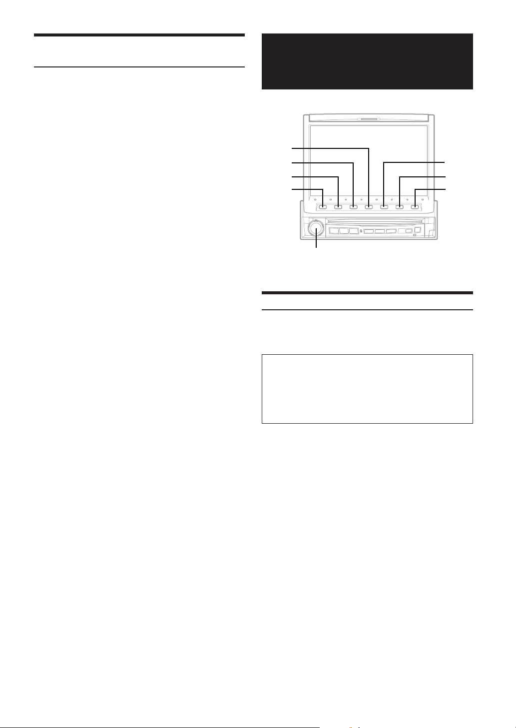
Displaying the Category/Channel Name Title
List
MobileHub™ Link
In XM mode, press LIST/INPUT.
1
The category title list is displayed.
Turn the Rotary encoder to move the cursor to
2
the desired category.
Press the Rotary encoder.
3
The lowest channel in the selected category is tuned.
To display the channel name list
1 While the title List is displayed in step 2 above, press
6 (NEXT :).
The channel name in the selected category is switched
to the list display.
By pressing 5 (; BACK), the display returns to the
previous category title list.
2Turn the Rotary encoder to select the desired channel
name.
3Press the Rotary encoder.
The selected channel name program is tuned.
(Optional)
4
3
2
1
Rotary encoder
About MobileHub™ Link (Optional)
Connect a separately sold junction box and a portable telephone
(available from Nokia) to control the incoming and outgoing calls of
the portable telephone.
CAUTION
• Even with hands-free operation, a driver can be distracted
during telephone operation or receiving a call. For the
sake of safety, drivers are requested to refrain from
operating the telephone while driving.
• For the sake of safety, operations other than incoming
calls and Speed-Dial outgoing calls cannot be used.
5
6
7
40-EN
• If a portable telephone is connected, its address book, incoming
and outgoing history, short message history and standardized
sentences are downloaded to the junction box.
Please refer to the instruction manual of the junction box.
• When a portable telephone is not connected, “NO PHONE” is
displayed for at least 5 seconds, then the mode returns to the
original source mode.
• When the portable telephone is taken off the junction box during an
incoming or outgoing call, or during a hands-free call, the call will
be treated as an ordinary one by the portable telephone.
• When there is an incoming call while the power of IVA-D901 is
OFF, the power of IVA-D901 will turn ON automatically for a
hands-free call.
• Even if the power of the portable telephone is OFF, when IVAD901 is set to the telephone mode, the power of the portable
telephone will be turned ON.
• Even if the ACC power of the vehicle is turned OFF (the engine is
stopped) during a hands-free call, the call is not disconnected, and
an ordinary call by the portable telephone is possible.
• If there is an incoming call during operation (except an outgoing
call or talking), operation mode will end and switch to the
incoming or talking mode.
• An outgoing call from a portable telephone is also possible.
However, you cannot perform different operations at the same time
from a portable telephone and IVA-D901 as malfunction can result.
Page 43

•With a junction box connected outgoing, incoming, and sending
history will also be recorded in the portable telephone.
• While telephoning, Time Correction is set to normal (0.0ms) and
DEFEAT is also set to ON. When the call has finished, the unit
returns to the setting which you previously set.
• The telephone volume can be adjusted from the IVA-D901. The
volume you set during the call is memorized, and is automatically
applied again on the next call.
Telephone Reception
When this unit receives a call, the screen is
1
switched to RINGING display of Telephone mode.
When AUTO call (setting of AUTO/MANUAL call
2
page 32) is selected, CONNECT display appears
and this unit enters AUTO call mode in 3 seconds
after receiving.
To cut the call, press 2 ( ). Or the call is
3
automatically cut in 5 seconds after finishing.
The screen returns to the previous source mode.
To input any number or symbol during call:
1Press 3 (TENKEY MODE) in the CONNECT display.
The DIAL Sending display appears.
2Turn the Rotary encoder to select your desired
Number or symbol, then press the Rotary encoder to
enter it.
3Press 7 (RETURN) to return the previous screen.
Calling
Calling by using the Speed Dial
You can place a call by retrieving one of the telephone numbers
registered in No. 1 to 9 of the address book.
Press the Rotary encoder for more than 2
1
seconds.
The Speed Dial display appears.
Press the desired function button.
2
If the telephone numbers have been registered in No.6 to
9, press 6 (6 - 9).
The Function Guide is switched to the function buttons 1
(6) to 4 (9).
Press 1 ( ) to start call.
3
To cut the call, press 2 ( ). Or the call is
4
automatically cut in 5 seconds after finishing.
• If no telephone number is registered in the selected function button,
"NO PRESET" is displayed for 5 seconds.
Press 7 (RETURN) to return to the Telephone menu display.
• When 1 (SPEED DIAL) is pressed in the Telephone menu
display, the Speed Dial display appears.
• By pressing your desired function button for more than 2 seconds
in step 2, you can start call directly.
Dial call
Input the telephone number using the dial.
Press and hold the Rotary encoder for more than
1
2 seconds.
The Speed Dial display appears.
Press 7 (RETURN).
2
The Telephone menu display appears.
Press 4 (DIRECT CALL).
3
The Direct Call display appears.
Turn the Rotary encoder to select the desired
4
number, then press the Rotary encoder to enter
the first digit.
;BACK or NEXT:: The cursor on the input number
DELETE: Deletes a blank space or a number.
Press 1 (CALL) to start call.
5
• The call is cut in 5 seconds after "NO NETWORK COVERAGE" is
displayed. Or press 2 ( ) to cut the call.
To listen to the answer-phone or to input numbers:
1In the CONNECT display, press 3 (TENKEY MODE).
The Dial Sending display appears.
2Turn the Rotary encoder to select your desired
Number or symbol, then press the Rotary encoder to
enter it.
3Press the 7 (RETURN) button to return to the previous
screen.
To cut the call, press 2 ( ). Or the call is
6
automatically cut in 5 seconds after finishing.
The screen returns to the previous source mode.
• If 7 (RETURN) is pressed in 5 seconds after the call is cut, the
Telephone menu display appears.
• When the call is cut, pressing 1 ( ) dials the number again.
moves left or right.
Pressing more than 2 seconds
deletes all input numbers.
Continued
41-EN
Page 44

Calling by the address book
From your vehicle, call from the address book registered in the
portable telephone.
Press and hold the Rotary encoder for more than
1
2 seconds.
The Speed Dial display appears.
Press 7 (RETURN).
2
The Telephone menu display appears.
Press 2 (PHONE BOOK).
3
The Phone Book display appears.
Turn the Rotary encoder to select a receiver,
4
then press the Rotary encoder .
The Select display appears.
• By pressing 1 (ALPHABET DN) or 2 (ALPHABET UP),
the names are listed in alphabteical order.
• If no data is in the PHONE BOOK, "NO MEMORY" is
displayed.
Press 7 (RETURN) to return to the Telephone menu display.
Press 1 ( ) to place the call.
5
To cut the call, press 2 ( ). Or the call is
6
automatically cut in 5 seconds after finishing.
Calling by the outgoing / incoming /
absent incoming history
You can place a call to one of the last 999 calls by the outgoing/
incoming/absent incoming history.
Press and hold the Rotary encoder for more than
1
2 seconds.
The Speed Dial display appears.
Press 7 (RETURN).
2
The Telephone menu display appears.
Press 3 (CALL LOG).
3
The Call log display appears.
Press either 1 (DIALED NUM.), 2 (MISSED
4
CALLS) or 3 (RECEIVE CALLS).
DIALED NUM.: Outgoing history list display
MISSED CALLS: Absent incoming history list display
RECEIVE CALLS: Incoming history list display
• If no history is registered to any of the lists, NO MEMORY is
displayed.
To return to Telephone menu display, press 7 (RETURN).
Turn the Rotary encoder to select a receiver, then
5
press the Rotary encoder.
The Select display appears.
Press 1 ( ) to start call.
6
To cut the call, press 2 ( ). Or the call is
7
automatically cut in 5 seconds after finishing.
SMS (Short Message Service) Operation
You can receive messages, show the contents of messages, and send
standardized sentences.
When a message is received, an icon is indicated on the display.
Receiving a Short Message
Press the Rotary encoder for more than 2
1
seconds.
The Speed Dial display appears.
Press 7 (RETURN).
2
The Telephone menu display appears.
Press 5 (SMS READ).
3
The SMS Read display appears.
Turn the Rotary encoder to select one of the
4
received message.
Press the Rotary encoder.
5
The SMS Inbox display appears.
The contents of the received message is displayed up to
140 letters.
REPLY: Replies to the sender by return mail.
USE NUMBER: Replies to the sender by phone. The
RETURN: Returns to the SMS Read display.
• When the unit receives a message, the new reception icon appears.
Standardized sentences can be selected
in the display (refer to “Sending a
Standardized Sentence,” page 43).
Select display appears. Place a call by
pressing 1 ( ).
42-EN
Page 45

Sending a standardized sentence
You can select a standardized sentence when you send a mail.
Press and hold the Rotary encoder for more than
1
2 seconds.
The Speed Dial display appears.
Press 7 (RETURN).
2
The Telephone menu display appears.
Pres the 6 (SMS WRITE).
3
The Standardized sentences are displayed.
Turn the Rotary encoder to select your desired
4
sentence.
Press the Rotary encoder.
5
The Send menu display appears.
Press either 1 (PHONE BOOK) to 3 (DIRECT
6
CALL) of the Function Guide to select the address.
To send from the PHONE BOOK or the CALL LOG
In the phone book display or the call log display,
7
turn the Rotary encoder to select the address.
Then press the Rotary encoder to enter it.
The select display appears.
Press 1 ( ) to send.
8
The SMS send display appears, and the mail is sent.
To send from the DIRECT CALL
In the direct call display, turn the Rotary encoder
7
to select the number. Then press the Rotary
encoder to enter it.
Press 1 (CALL).
8
The SMS send display appears and the mail is sent.
•To reply by REPLY of “SMS (Short Message Service) Operation”
(page 42), press 6 (SEND) on the Send menu display to send.
• If TEL mode is canceled by power off, etc., in the middle of making
a short message, the unfinished message is not saved.
43-EN
Page 46
External Audio Processor
(Optional)
When an external audio processor is connected to this unit, you can
operate it from this unit. Some audio processors may not be operated.
When PXA-H510 or PXA-H900 is connected, some of the operations
may not be performed from this unit. In this case, operate them in the
connected product. Explanations below is the case when PXA-H700
or PXA-H701 is connected for example.
Refer also to the operating instructions of the connected audio
processor.
• While your car is running, only A.PROC list is displayed. Carry
out the operation related to any setting while your car stops.
• The adjustments or settings performed on the connected audio
processor cannot be operated properly from this unit.
To display the Audio processor mode screen:
To watch a video source, your vehicle must be parked with
the ignition key in the ACC or ON position. To do this, follow
the procedure below.
1. Bring your vehicle to a complete stop at a safe
location. Engage the parking brake.
2. Keep pushing the foot brake and release the parking
brake once then engage it again.
3. When the parking brake is engaged for the second
time, release the foot brake.
•For automatic transmission vehicles, place the transmission
lever in the Park position.
Now, the locking system for the Audio processor mode
operation has been released. Engaging the parking brake
can reactivate the Audio processor mode, as long as the
car's ignition has not been turned off. It is not necessary to
repeat the above procedure (1 through 3), of “To display
the Audio processor mode screen.”
Each time the ignition is turned OFF, perform the procedure
of “To display the Audio processor mode screen.”
Adjustment Procedure for Dolby Surround
Make the adjustments described below in order to reproduce Dolby
Digital and DTS sound with greater accuracy.
Adjustment procedure
Speaker setup (page 48)
1
(Turning the speakers to be used on and off and
setting their response)
B
Adjusting the speaker levels (page 50)
2
(Adjusting the signal output level to the various
speakers)
B
Mixing bass sound to the rear channel (page
49)
3
(Achieving smooth sound in the rear seat by mixing
the front audio signals with the rear speaker signals)
B
Adjusting the acoustic image (page 49)
(Adjusting the acoustic image to achieve a sound as
4
if the center speaker were directly in front of the
listener)
B
Achieving powerful high volume sound (page
49)
5
(Achieving energetic sound with even greater power,
like the sound in a movie theater)
44-EN
B
Adjusting the DVD level (page 50)
6
(Adjust the volume (signal level) in the Dolby Digital,
Pro Logic II, DTS and PCM modes.)
B
Storing settings in the memory (page 50)
(Storing all the settings and adjustments made on the
7
IVA-D901 (not only the above settings/adjusts) in the
memory)
In case of combining the Automatic adjustments etc.
We recommend to make the Automatic adjustments before the Dolby
Surround adjustments.
Page 47
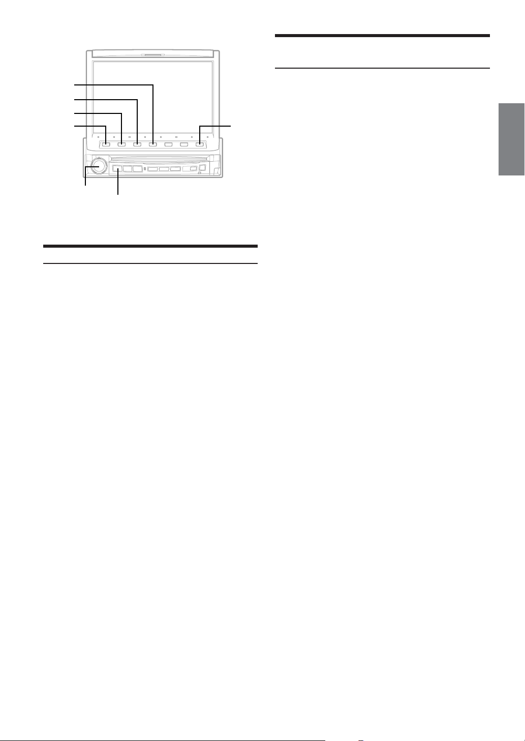
Set MX Mode of the External Audio
Processor
4
3
2
1
Rotary encoder
SOURCE/POWER
7
Setting the Speakers
Check that defeat mode is off.
1
Press SOURCE/POWER.
2
The main menu is displayed.
Press 4 (A.PROC).
3
The A.PROC (Audio processor) list display appears.
Turn the Rotary encoder to select SPEAKER
4
SELECT.
The Function Guide changes.
Press 1 (SETUP).
5
The SPEAKER SELECT list display appears.
Turn the Rotary encoder to select a speaker to
6
be set.
The Function Guide changes.
Press the function button to set the selected
7
speaker.
FRONT1: OFF/FULL (Full Range)/TW (Tweeter)
FRONT2: OFF/ON
REAR: OFF/ON
CENTER/SUBW.:
• Set the speaker which is not connected to OFF.
• Settings above can be carried out even when the speaker is set to
OFF in “Speaker Setup.”
•In order to protect the speakers, if Tweeter is selected in Front 1,
there is no filter OFF (slope OFF) setting for H.P.F.
Fo r the same reason, the subwoofer low pass filter cannot be
turned off (the slope cannot be set to “OFF”).
•To use the subwoofer in MONO with PXA-H700 or PXA-H701
connected, connect the subwoofer to the subwoofer output terminal
of PXA-H700 or PXA-H701.
CENTER OFF/ON
SUB W. (Subwoofer) OFF/MONO/STEREO
Before performing the operations below, set MX (Media Xpander)
mode of the external audio processor to “AUTO.”
Check that defeat mode is off.
1
Press SOURCE/POWER.
2
The main menu is displayed.
Press 4 (A.PROC).
3
The A.PROC (Audio processor) list display appears.
Turn the Rotary encoder to select “Media
4
Xpander.”
The Function Guide changes.
Press 2 (ON), then press 3 (SETUP).
5
The MX list display appears.
OFF: To cancel MX mode for all music sources
Turn the Rotary encoder to select your desired
6
MX mode.
The screen shows the *Function Guide.
* Displays the function assigned for each button.
Press the Function button to switch the setting.
7
The level of the audio source can be adjusted. It is after
switching the audio source that the MX mode is applied.
MX CD (OFF, CD 1 to 3)
CD mode processes a large quantity of data. This data is
used to reproduce the sound cleanly by making use of the
data quantity.
MX MP3 (OFF, MP3 1 to 3) / MX XM (OFF, XM 1 to 3) / MX
MD (OFF, MD 1 to 3)
This corrects information that was omitted at the time of
compression. This reproduces a well-balanced sound close to
the original.
MX FM (OFF, FM 1 to 3)
The medium to high frequencies become more clear, and
produces well balanced sound in all the bands.
MX DVD (OFF, MOVIE 1 to 2)
The dialog portion of the video is reproduced more clearly.
(DVD MUSIC)
This disk contains a large quantity of data such as music clip.
MX uses this data to reproduce the sound accurately.
MX AUX 1 to 3 (OFF, MP3, MOVIE, MUSIC)
Choose the MX mode (MP3, MUSIC, or MOVIE) that
corresponds to the media connected.
To return to the previous display, press 7 (RETURN).
Press the function button to set the MX mode.
8
• The contents of MX set here is reflected to PXA-H700 or PXAH701.
• When OFF is selected, MX effect of each MX mode will be OFF.
• Each music source, such as radio, CD, and MP3 can have its own
MX setting.
• MX mode does not function when MX is ON for AM radio.
• XM, MD or AUX is displayed only when each product is connected.
Continued
45-EN
Page 48
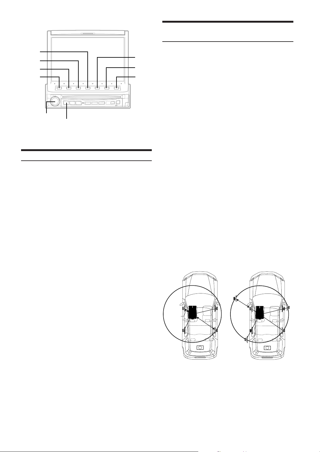
Performing Time Correction Manually (TCR)/
Swithing the Phase
4
3
2
1
Rotary encoder
SOURCE/POWER
5
6
7
X-OVER Adjustment
Check that defeat mode is off.
1
Press SOURCE/POWER.
2
The main menu is displayed.
Press 4 (A.PROC).
3
A.PROC (Audio processor) list display appears.
Turn the Rotary encoder to select “X-OVER.”
4
Press 1 (SETUP L/R) or 2 (SETUP L+R).
5
X-OVER adjustment display appears.
L/R: Different adjustment values can be set for the left
and right channels.
L+R: Sets the same adjustment values for the left and
right channels.
Turn the Rotary encoder to select the speaker to
6
be set.
Press the function button to adjust the selected
7
speaker.
FREQ. ;DN/UP:: Adjust the H.P.F. or L.P.F. cutoff
SLOPE ;DN/UP:: Adjust the H.P.F. or L.P.F. slope.
LEVEL ;DN/UP:: Adjust the level.
Repeat steps 6 and 7 to adjust other channels.
8
Press 7 (RETURN) to return to the previous
9
display.
• When the speaker is set to the “OFF” mode, X-OVER for that
speaker cannot be set. Refer to “Setting the Speakers” (page 45).
• Check the playback frequencies of the connected speakers before
adjusting.
•In order to protect the speakers, there is no OFF setting for the
subwoofer low pass filter (the slope remains the same).
• Even if Tweeter is selected for FRONT 1, the filter OFF (slope
OFF) of the H.P.F. can be set. If the slope is set to OFF, speakers
may be damaged. Take care with this setting.
frequency.
The adjustable bands differ
according to the channel (speaker).
Because of the particular conditions inside the vehicle, there can be
major differences in the distances between the various speakers and
the listening position. It is possible to calculate the optimum
correction values and eliminate the time error at the listening position
yourself using this function. You can also use this function to switch
the phase.
Check that Defeat mode is off.
1
Sit in the listening position (the driver’s seat, for
2
example) and measure the distance (in meters)
between your head and the various speakers.
Calculate the difference in distance between the
3
farthest speaker and the other speakers.
L = (distance of farthest speaker)
– (distance of other speakers)
Divide the distances calculated for the different
4
speakers by the speed of sound (343 m/s
temperature 20°C).
This value is the time correction value for the various
speakers.
Concrete examples
Calculating the time correction value for the front left speaker
on the diagram below.
Conditions:
Distance between farthest speaker and listening position:
2.25 m (88-3/4")
Distance between front left speaker and listening position:
0.5 m (20")
Calculation:
L = 2.25 m (88-3/4") – 0.5 m (20")= 1.75 m (68-3/4")
Compensation time = 1.75 ÷ 343 x 1000 = 5.1 (ms)
In other words, setting the time correction value for the front
left speaker to 5.1 (ms) sets a virtual distance matching the
distance to the farthest speaker.
5.1ms
0.5m
2.25m
The sound is uneven
because the distance
between the listening
position and the different
speakers is different.
The difference in the
distance between the front
left and rear right speakers
is 1.75 meters (68-3/4").
Time correction eliminates
the difference between the
time required for the sound
from the different speakers
to reach the listening
position.
Setting the time correction of
the front left speaker to 5.1
ms makes it possible to
coordinate the distance from
the listening position to the
speaker.
46-EN
Page 49

Press SOURCE/POWER.
5
The main menu is displayed.
Press 4 (A.PROC).
6
A.PROC (Audio processor) list display appears.
Turn the Rotary encoder to select "TCR/PHASE".
7
The Function Guide changes.
Press 1 (SETUP L/R) or 2 (SETUP L+R).
8
TCR/PHASE adjustment display appears.
L/R: Different adjustment values can be set for the left
and right channels.
L+R: Sets the same adjustment values for the left and right
channels.
Turn the Rotary encoder to select a speaker to
9
be set.
Press the 1 (TIME ; DN) or 2 (TIME UP :) to
10
adjust the time revision value (1 step = 0.05 ms).
Press 3 (0°) or 4 (180°) to switch phase.
11
Repeat steps 9 to 11 to adjust other channels.
12
Press 7 (RETURN) to return to the previous
13
display.
• When the speaker is set to the “OFF” mode, the TCR for that
speaker cannot be set. Refer to “Setting the Speakers” (page 45).
• The adjustment value for FRONT2 which is adjusted in time
correction, is also applied to the front speakers in “Bass Focus”
(page 48).
•
The adjustment (AUTO TCR) cannot be automatically set on this unit.
Graphic Equalizer Adjustments
The graphic equalizer allows you to modify the sound using 31 bands
each for the front (left and right), rear (left and right) and center
speakers. An additional 10 bands are available for the subwoofer. This
allows you to customize the sound to suit your taste.
Check that the Defeat mode is off.
1
Press SOURCE/POWER.
2
The main menu is displayed.
Press 4 (A.PROC).
3
The A.PROC (Audio processor) list display appears.
Turn the Rotary encoder to select "G.EQ
4
(Graphic EQ)".
The Function Guide changes.
Press 2 (ON), then press 3 (SETUP L/R) or 4
5
(SETUP L+R).
G.EQ adjustment display appears.
L/R: Different adjustment values can be set for the left
and right channels.
L+R: Sets the same adjustment values for the left and
right channels.
When you do not adjust it, set to OFF.
Press the function button of your desired speaker
6
(channel).
The Function Guide changes.
Turn the Rotary encoder to select a frequency to
7
be adjusted.
Press 1 (LEVEL; DN) or 2 (LEVEL UP :) to
8
adjust the level.
Press 7 (RETURN) to return to the Function Guide in
step 6.
Repeat steps 6 to 8 to adjust other frequencies.
9
• When the speaker is set to the “OFF” mode, the graphic equalizer
for that speaker cannot be set. Refer to “Setting the Speakers”
(page 45).
• Check the playable frequency ranges of the connected speakers
before making the equalizer adjustments. If the speaker’s playable
frequency range is 55 Hz to 30 kHz, for example, adjusting the 40
Hz or 20 Hz band has no effect. Additionally, you may overload
and damage the speakers.
• When graphic EQ is adjusted, the adjustment for parametric EQ
becomes ineffective.
Parametric Equalizer Adjustments
The frequency bands of the graphic equalizer are fixed. This makes it
very difficult to correct for undesired peaks and dips at specific
frequencies. The parametric equalizer’s center frequency can be tuned
to these specific frequencies. Then, the bandwidth (Q) and level are
fine-tuned, independently, to make the necessary corrections. The
parametric equalizer function is an advanced tool for serious
audiophiles.
Check that Defeat mode is off.
1
Press SOURCE/POWER.
2
The main menu is displayed.
Press 4 (A.PROC).
3
The A.PROC (Audio processor) list display appears.
Turn the Rotary encoder to select "P.EQ
4
(Parametric EQ)".
The Function Guide changes.
Press 2 (ON), then press 3 (SETUP L/R) or 4
5
(SETUP L+R).
P. EQ adjustment display appears.
L/R: Different adjustment values can be set for the left
and right channels.
L+R: Sets the same adjustment values for the left and
right channels.
When you do not adjust it, set to OFF.
Press the function button of your desired speaker
6
(channel).
The Function Guide changes.
Turn the Rotary encoder to select a frequency to
7
be adjusted.
Press the function button to adjust as follows.
8
FREQ. ;DN or UP :: Selects the frequency.
LEVEL ;DN or UP :: Adjusts the level.
WIDTH ;DN or UP :: Adjust the band width.
Press RETURN to return to the function guide in step 6.
Repeat steps 6 to 8 to adjust other bands.
9
• When the speaker is set to the “OFF” mode, the parametric
equalizer for that speaker cannot be set. Refer to “Setting the
Speakers” (page 45).
• It is not possible to adjust the frequencies of adjacent bands within
7 steps.
• Check the playable frequency ranges of the connected speakers
before making the equalizer adjustments. If the speaker's playable
frequency range is 55 Hz to 30 kHz, for example, adjusting the 40
Hz or 20 Hz band has no effect. Additionally, you may overload
and damage the speakers.
• When the parametric EQ is adjusted, the adjustment for graphic
EQ becomes ineffective.
47-EN
Page 50
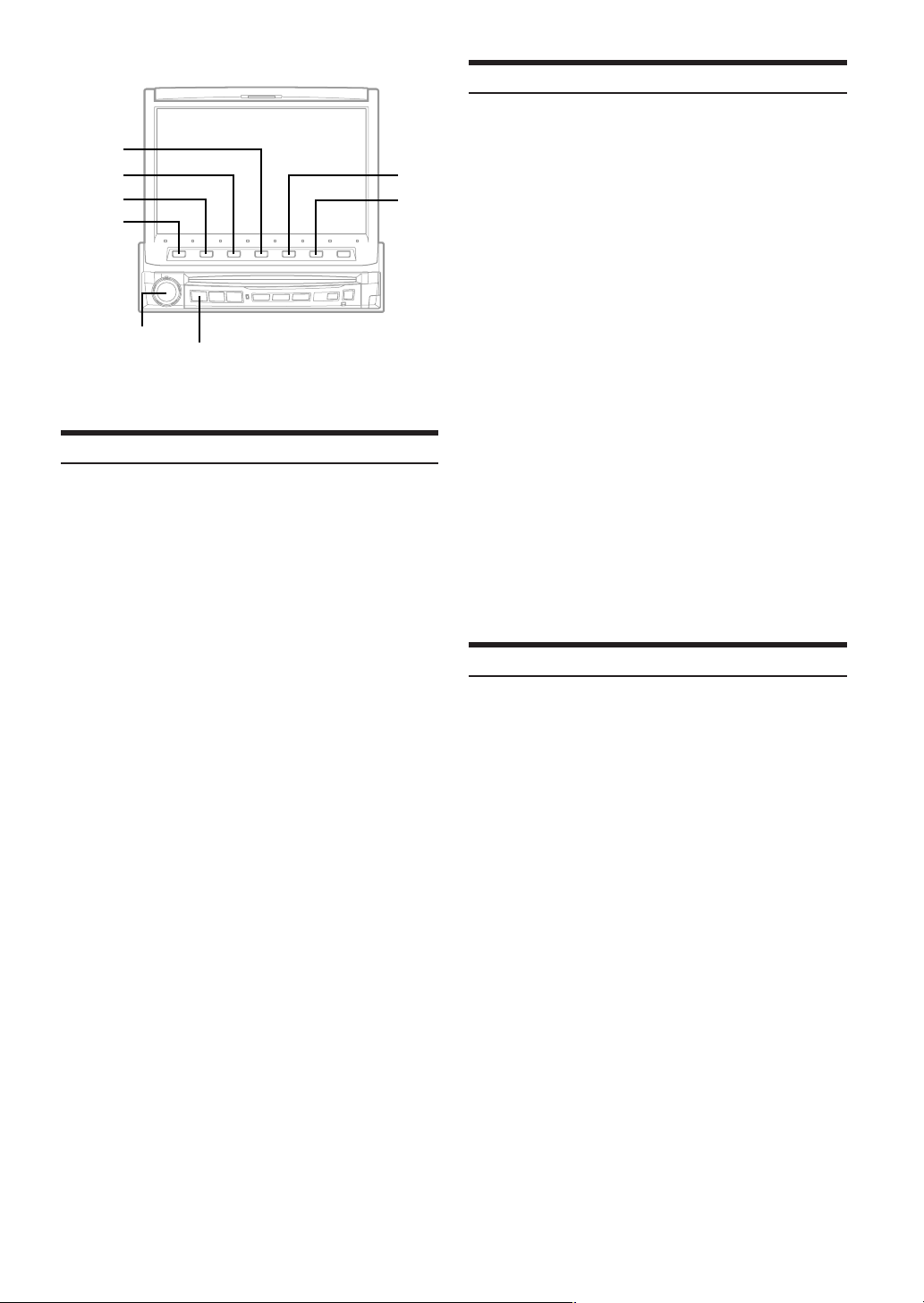
4
3
2
1
Rotary encoder
SOURCE/POWER
BASS COMP. Setting
The sound of low frequencies can be adjusted to suit your tastes.
Check that the Defeat mode is off.
1
Press SOURCE/POWER.
2
The main menu is displayed.
Press 4 (A.PROC).
3
The A.PROC (Audio processor) list display appears.
Turn the Rotary encoder to select “BASS SOUND
4
CONT.”.
The Function Guide changes.
Press 1 (SETUP).
5
Bass Sound list display appears.
Turn the Rotary encoder to select “BASS COMP”.
6
The Function Guide changes.
Press the function button of your desired mode.
7
As the bass level increases in order of MODE1 - 3, you
can enjoy listening to powerful sound.
When you do not adjust any of them, set to OFF.
48-EN
Bass Focus
The time difference between the front-rear/left-right speakers, can be
adjusted a pair at a time. Audible time correction can be made from
0.00 ms to 20.00 ms in 201 steps (0 to 2.00).
5
6
Check that the Defeat mode is off.
1
Press SOURCE/POWER.
2
The main menu is displayed.
Press 4 (A.PROC).
3
The A.PROC (Audio processor) list display appears.
Turn the Rotary encoder to select “BASS SOUND
4
CONT.”.
The Function Guide changes.
Press 1 (SETUP).
5
The Bass Sound Cont list display appears.
Turn the Rotary encoder to select “BASS
6
FOCUS.”
The Function Guide changes.
Press 3 (FRONT), 4 (LEFT), 5 (RIGHT) and 6
7
(REAR) to select the front, rear, left and right
speakers.
Press 1 (TIME ; DN) or 2 (TIME UP :) to set
8
the step of front/rear and left/right.
For setting another channel (speaker), repeat steps
9
7 and 8.
• The setting mode in Bass Focus is reflected in the time correction.
Speaker Setup
The PXA-H700 can be set according to the playable frequency range
of your speakers.
Check the playable frequency range of the speakers (not including the
subwoofer) before performing this operation to verify whether the
speakers can play low frequencies (of about 80 Hz or less).
•Avoid stopping, pausing, switching the disc, cueing, fastforwarding or switching the audio channel of this unit while
making this adjustment. The setting is canceled if Decode mode is
switched.
Check that Defeat mode is off.
1
Press SOURCE/POWER.
2
The main menu is displayed.
Press 4 (A.PROC).
3
The A.PROC (Audio processor) list display appears.
Turn the Rotary encoder to select “SPEAKER
4
SETUP”.
Press 1 (SETUP).
5
The SPEAKER SETUP list display appears.
Turn the Rotary encoder to select a speaker.
6
Press the function button to select a speaker frequency.
7
∗
1
OFF
: When no speaker is connected.
SMALL: When a speaker that cannot play low
LARGE
∗1: It is not possible to set the front speakers to “OFF”.
∗2: If the front speakers are set to “SMALL”, the rear and
frequencies (80 Hz or less) is connected.
∗
2
: When a speaker that can play low frequencies
(80 Hz or less) is connected.
center speakers cannot be set to “LARGE.”
Page 51

• Subwoofer can be set to “ON” or “OFF” only.
• If the center speaker is turned “OFF,” the center channel's audio
signals are added to the audio signals output from the front
speakers.
• If you set the speaker response to “OFF,” also set the speaker
setting to “OFF.” (page 45.)
•Perform the setup for all the speakers (“Front,” “Center,” “Rear”
and “Subwoofer”). If not, the sound may not be balanced.
• When center is set to “OFF,” the setting is ineffective even if center
is set with this function.
• Through changing the settings on each speaker, a change in the
output of the other speakers may occur due to the setting
requirements.
• When using the PRO LOGIC II, if the rear speaker is set to
“LARGE”, then there will be no output from the subwoofer.
Setting of Dolby 5.1ch
Check that Defeat mode is off.
1
Press SOURCE/POWER.
2
The main menu is displayed.
Press 4 (A.PROC).
3
The A.PROC (Audio processor) list display appears.
Turn the Rotary encoder to select “DOLBY 5.1CH
4
SETUP.”
The Function Guide changes.
Press 1 (SETUP).
5
The DOLBY 5.1CH SETUP list display appears.
Set the items below as you desire.
Adjusting the acoustic image
In most installations, the center speaker must be placed directly
between the front passenger and driver. Using this function, the center
channel information is distributed to the left and right speakers. This
creates an acoustic image simulating a center speaker directly in front
of each listener. Adjusting the center width in PL II MUSIC (see
“Using the Pro Logic II mode,” page 51), makes this function
ineffective.
•Avoid stopping, pausing, switching the disc, cueing, fastforwarding or switching the audio channel of this unit while
making this adjustment. The setting is canceled if the Decode mode
is switched.
1Turn the Rotary encoder to select BI-PHANTOM.
2Press 2 (ON).
By pressing 1 (OFF), BI-PHANTOM is set to OFF.
3Press 3 (LEVEL ; DN) or 4 (LEVEL UP :) to adjust
the level.
The level can be adjusted within the range of -5 to +5.
The higher the level, the more the position of the center
speaker is shifted to the sides.
• This adjustment is effective when the setting of the center speaker
to SMALL or LARGE in the speaker setup settings.
• This adjustment is ineffective when the speaker is set to CENTER
OFF in “Setting the Speaker” (page 45).
Mixing bass sound to the rear channel
This function mixes the front channel audio signals to the audio
signals output from the rear speakers, improving the sound in the
vehicle’s rear seat.
•Avoid stopping, pausing, switching the disc, cueing, fastforwarding or switching the audio channel of this unit while
making this adjustment. The setting is canceled if the Decode mode
is switched.
1Turn the Rotary encoder to select REAR MIX.
2Press 2 (ON).
By pressing 1 (OFF), REAR MIX is set to OFF.
3Press 3 (LEVEL ;DN) or 4 (LEVEL UP :) to adjust
the level.
The level can adjusted in five steps: –6, –3, 0, +3 and
+6. The higher the level, the more bass is output from
the rear speakers. (The effect differs according to the
software (DVD, etc.).)
• This adjustment is ineffective when the rear speaker setup setting is
set to “OFF.”
•For linear PCM signals, the voice is output from the rear speaker
regardless of the REAR FILL and REAR MIX setting.
Achieving powerful high volume sound
With Dolby Digital, the dynamic range is compressed so that
powerful sound can be achieved at regular volume levels. This
compression can be canceled to achieve an energetic sound with even
greater power, like the sound in a movie theater.
This function works only in the Dolby Digital mode.
1Turn the Rotary encoder to select LISTENING MODE.
2Press 1 (STD) or 2 (MAX).
STD: For powerful sound at regular volume levels
MAX: For powerful sound at high volumes
•Keep the volume to a level at which sounds outside the vehicle can
still be heard.
Continued
49-EN
Page 52
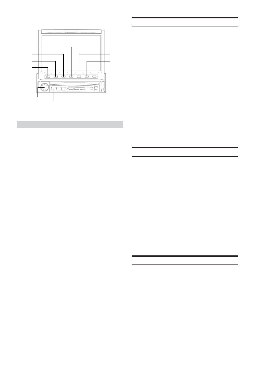
4
3
2
1
Rotary encoder
SOURCE/POWER
5
6
Adjusting the speaker levels
The test tones help to make the volume adjustments of the different
speakers. When levels are equal, a strong sense of presence can be
heard from the different speakers at the listening position.
•Avoid stopping, pausing, switching the disc, cueing, fastforwarding or switching the audio channel of this unit while
making this adjustment. The setting is canceled if the decode mode
is switched.
1Turn the Rotary encoder to select OUTPUT LEVEL.
2Press 1 (AUTO).
Test tone output is repeated for each of the different
speaker channels. They will be repeated in the order
shown below.
If no operation is performed for 2 seconds, the channel
switches to the next channel.
Left → Center → Right → Right Surround →
Left surround → Left
3 While the test tones are being produced from the
speakers, press 2 (LEVEL ; DN) or 3 (LEVEL UP
:) to adjust so that the volume of the different speakers
is equal.
• The adjustment range for the different speakers is
–10 dB - +10 dB.
• Adjust based on the front speakers.
• If a speaker is set to off mode, that speaker’s level adjustment
cannot be made.
Refer to “Speaker Setup” (page 48).
Adjusting the DVD Level
The volume (signal level) for Dolby Digital, Dolby PL II, DTS and
PCM modes can be set.
•Avoid stopping, pausing, switching the disc, cueing, fastforwarding or switching the audio channel of this unit while
making this adjustment. The setting is canceled if the Decode mode
is switched.
Check that Defeat mode is off.
1
Press SOURCE/POWER.
2
The main menu is displayed.
Press 4 (A.PROC).
3
The A.PROC (Audio processor) list display appears.
Turn the Rotary encoder to select “DVD LEVEL.”
4
Press 1 (SETUP).
5
The DVD LEVEL list display appears.
Turn the Rotary encoder to select a mode to be
6
adjusted.
Press 1 (LEVEL ;DN) or 2 (LEVEL UP :) to
7
adjust the level.
The level can be adjusted in the range of –5 to +5.
Storing Settings in the Memory
Adjustment or setting contents can be stored.
Contents that can be stored vary depends on the audio processor used.
Check that Defeat mode is off.
1
Press SOURCE/POWER.
2
The main menu is displayed.
Press 4 (A.PROC).
3
The A.PROC (Audio processor) list display appears.
Turn the Rotary encoder to select “PRESET
4
MEMORY.”
The Function Guide changes.
Press one of 1 (P. SET1) to 6 (P.SET6) for more
5
than 2 seconds.
The setting contents are stored.
• The stored contents will not be deleted even when the battery
power cord is detached.
Getting out the Preset Memory
50-EN
Check that Defeat mode is off.
1
Press SOURCE/POWER.
2
The main menu is displayed.
Press 4 (A.PROC).
3
The A.PROC (Audio processor) list display appears.
Turn the Rotary encoder to select “PRESET
4
MEMORY.”
The Function Guide changes.
Press one of 1 (P. SET1) to 6 (P.SET6) to select
5
the preset memory you want to get out.
• It takes a few moment to get out the preset memory.
Page 53

Using the ProLogic II Mode
Pro Logic processing can be conducted on the music signals recorded
on two channels to achieve Dolby Pro Logic II surround sound. For
two-channel Dolby Digital and DTS signals, there is also a “REAR
FILL” function for outputting the signals of the front channel to the
rear channel.
Check that Defeat mode is off.
1
Press SOURCE/POWER.
2
The main menu is displayed.
Press 4 (A.PROC).
3
The A.PROC (Audio processor) list display appears.
Turn the Rotary encoder to select “DOLBY PL II.”
4
The Function Guide changes.
Press 1 (SETUP).
5
The DOLBY PL II adjustment display appears.
Turn the Rotary encoder to select DOLBY PL II.
6
Press the function button to select your desired
7
mode.
PL II MOVIE:
Suits the stereo TV shows and all programs
encoded in Dolby Surround. It improves the sound
field directivity to near that of discrete 5.1-channel
sound.
PL II MUSIC:
Can be used for all stereo music recordings, and
provides a wide, deep sound field.
REAR FILL:
Depending on the input signals, the sound may only
be output from the front speakers. In this case, the
"REAR FILL" function can be used to output signals
from the rear speakers as well.
OFF: Turns DOLBY PL II function to OFF.
If PL II MUSIC is selected, the center width can be adjusted
with following operations.
This function offers the optimum vocal position by adjusting
the center channel position between the center speaker and
the L/R speaker. (The adjustments established in “Adjusting
the acoustic image” (page 49) are ineffective while this
function is activated.)
1Turn the Rotary encoder to select CENTER WIDTH
CONT.
The Function Guide changes.
2Press 2 (ON).
By pressing 1 (OFF), the CENTER WIDTH CONT
function is turned to OFF.
3Press 3 (LEVEL ;DN) or 4 (LEVEL UP :) to adjust
the level.
The level can be adjusted between 0 to 7. When the
level increases, the center channel position moves from
the center speaker position to both sides.
• This adjustment is effective when the setting of the center
speaker is SMALL or LARGE in the speaker setup settings.
•Avoid stopping, pausing, switching the disc, cueing, fastforwarding or switching the audio channel of this unit while
making this adjustment. The setting is canceled if the Decode mode
is switched.
• This adjustment is ineffective when the speaker is set to CENTER
OFF in “Setting the Speaker” (page 45).
• This function only works with two-channel signals. This operation
is ineffective when 5.1-channel DTS or Dolby Digital signals are
input.
• If the setting of REAR FILL is made when REAR MIX is ON, sound
is unchanged in the rear fill setting because REAR MIX is given
priority during 2 channel decoder other than linear PCM.
•For linear PCM signals, the voice is output from the rear speaker
regardless of the REAR FILL and REAR MIX setting.
Linear PCM Setting
The output when playing discs recorded in linear PCM can be set to 2
or 3 channels.
Check that Defeat mode is off.
1
Press SOURCE/POWER.
2
The main menu is displayed.
Press 4 (A.PROC).
3
A.PROC (Audio processor) list display appears.
Turn the Rotary encoder to select "PCM MODE".
4
The Function Guide changes.
Press 1 (2CH) or 2 (3CH).
5
2CH: 2ch output (L/R)
3CH: 3ch output (L/R/CENTER)
• This adjustment is ineffective when the speaker is set to CENTER
OFF in “Setting the Speaker” (page 45).
51-EN
Page 54
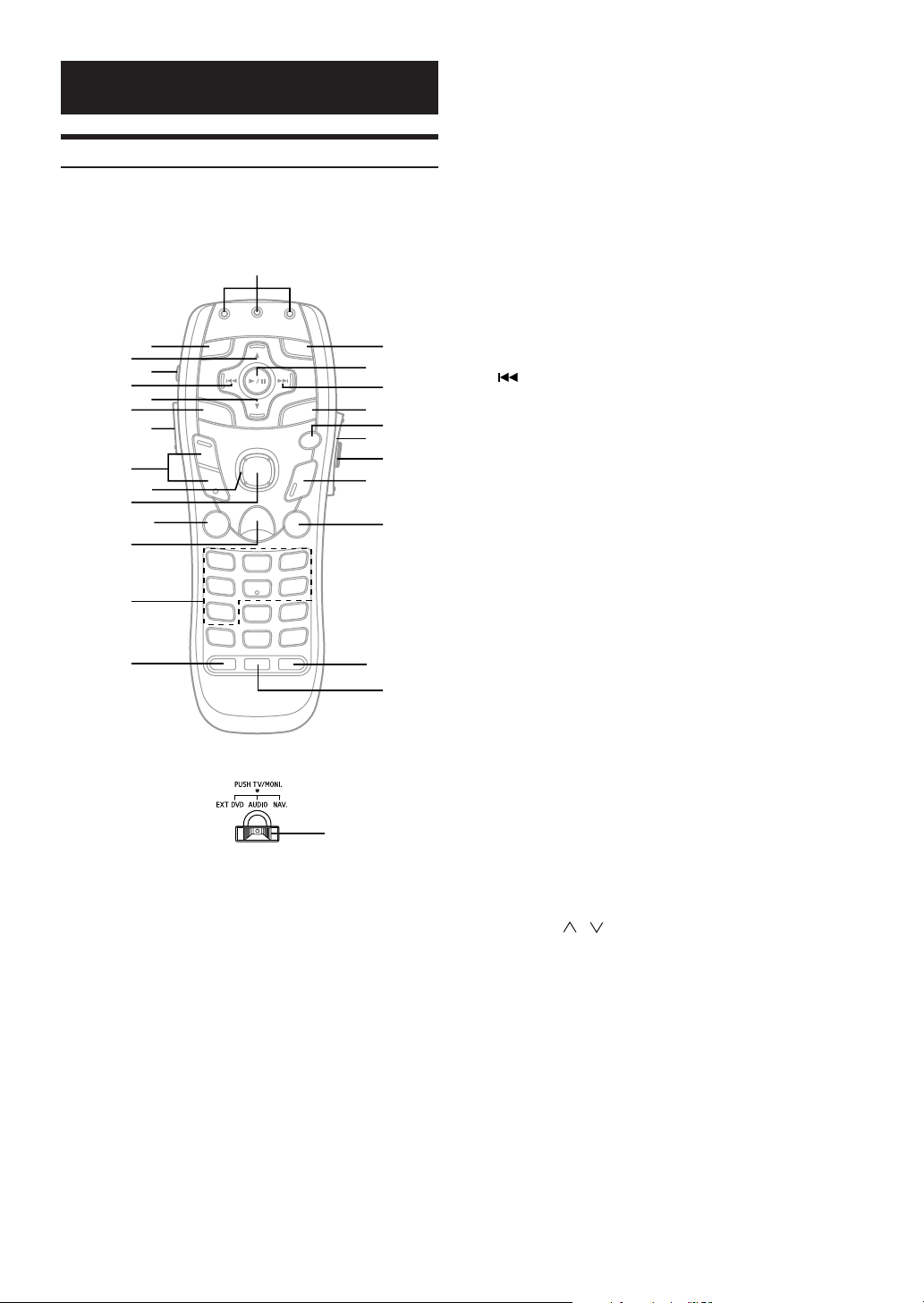
Remote Control
Operating for the IVA-D901
Set the mode selector switch to “AUDIO” to perform operations on
the IVA-D901.
1
3
5
7
9
"
$
%
&
2
4
6
8
!
#
=
(Rear of the Remote Control)
;
/
-
+
)
<
:
.
,
~
(
1 AUDIO/NAV./EXT DVD Transmission Indicator
When the mode selector switch is switched, the
transmission indicators for the various modes light for
several seconds.
2 A.PROC Button
Press the button to call the audio processor list.
3 , Button
Radio mode: Selects, in ascending order, stations
programmed into the radio's presets.
MP3 mode: Folder Select (UP) Button to selects the
folder.
CD Changer mode:
DISC Select (UP) Button selects a disc in
ascending order.
4 POWER Button
Turns the power on/off.
5 Button
Radio mode: SEEK (DN) Button
CD/Changer mode:
Press the button to go back to the
beginning of the current track. Press and
hold to fast reverse.
MP3 mode: Press the button to go back to the
beginning of the current file.
DVD/Video CD:
Move to the desired position on the disc.
During playback, press and hold for more
than 1 second to reverse the disc at double
speed. Hold for more than 5 seconds to
reverse the disc at 8 times the normal
speed.
6 9 Button
Radio mode: Selects, in descending order, stations
programmed into the radio's presets.
MP3 mode: Folder Select (DN) Button selects the
folder.
CD Changer mode:
DISC Select (DN) Button selects a disc in
descending order.
7 V. SEL Button
Switches the screen when the unit is used in combination
with a separately sold monitor, etc. (Simul function)
By pressing the button for more than 2 seconds, Simul
function is canceled.
8 LIGHT Button
Lights the indicator.
9 VOLUME / Button
Increase or decreases the volume level.
! Joystick
Selects an item displayed in the screen.
" ENTER Button
Enters the selected item.
# MUTE Button
Lowers the volume by 20 dB instantly. Press the button
again to cancel.
By pressing the button for more than 2 seconds, the
monitor opens or closes.
52-EN
Page 55

$ MENU/SETUP Button
DVD mode: Shows the menu display.
Video CD mode:
Tur ns PBC ON or OFF. (for Video CD with
PBC functions)
By pressing it more than 2 seconds, Setup list display
appears.
% Numeric Keypad
The functions displayed in the Function Guide of the main
menu are assigned to 1 to 7 buttons.
& AUDIO Button
DVD mode:Switches audio.
( SUB T. Button
DVD mode:Switches the subtitle.
) ANGLE Button
DVD mode:Switches the angle of the picture.
~ RTN Button
DVD/Video CD (PBC ON) mode:Returns to the previous
display. (Does not return in some discs.)
+ DISP/TOP.M Button
DVD/Video CD mode:
Shows playback status.
DVD mode: By pressing more than 2 seconds, shows
the menu display.
, REAR Button
Point the remote control to the remote control sensor of
the IVA-D901, and press and hold for at least 2 seconds
to switch the remote control sensor.
To switch to the other remote control sensor, press REAR
pointing to the remote control sensor of the currently
selected external product.
- TILT / Button
Adjusts the angle of the movable audio display.
The angle moves continuously by keeping it pressed.
. L Button
Performs stop.
/ SOURCE Button
Selects the audio source.
: Button
Radio mode: SEEK (UP) Button
CD changer mode:
Press the button to advance to the
beginning of the next track. Press and hold
to fast forward.
MP3 mode: Press the button to advance to the
beginning of the next file.
DVD/Video CD:
• Move to the desired position on the disc.
• During playback, press and hold for
more than 1 second to forward the disc
at double speed. Hold for more than 5
seconds to forward the disc at 8 times
the normal speed.
• When pressed and held in while in the
pause mode, the disc is played in slow
motion at 1/8th the normal speed. When
held in for 5 more seconds, the slow
motion speed switches to 1/2 the normal
speed.
• The picture is forwarded by one frame
each time the button is pressed in the
pause mode.
; Button
Radio mode: Chooses the tuning mode.
By pressing it more than 2 seconds,
Automatic Memory will be operated.
Disc mode: Switches between play and pause.
< BAND Button
Radio mode: Changes the band.
CD/Changer mode:
Switches the disc mode.
= MODE Change Switch
Sets to “AUDIO” to operate the IVA-D901.
Sets to “EXT DVD” to operate a separately sold DVD
product.
Sets to “NAV.” to operate a separately sold navigation
product.
When pressed, the mode switches to the TV mode.
Operate while the transmission indicator is flashing.
53-EN
Page 56
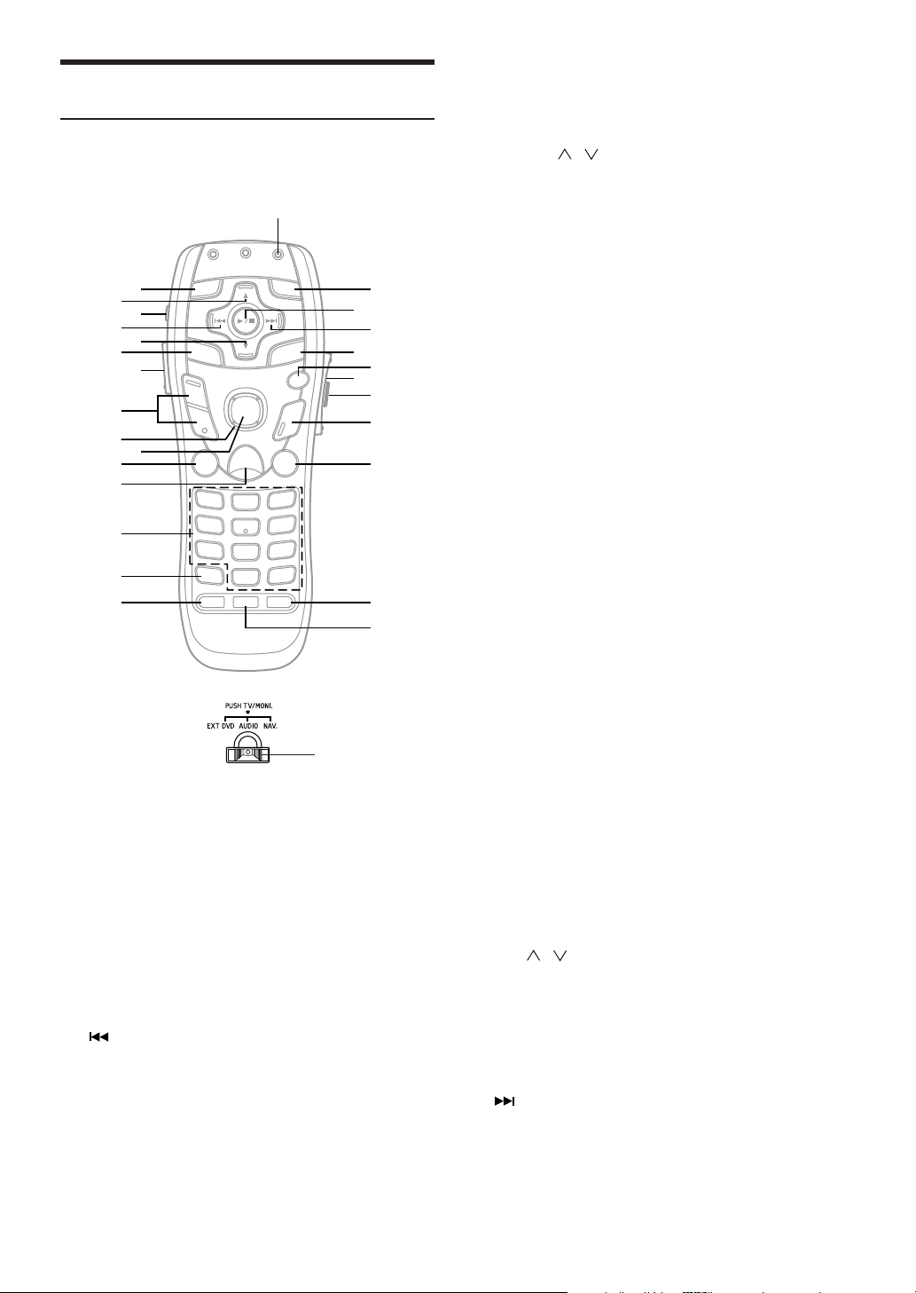
Operating the DVD player/DVD changer
(sold separately)
Set the mode selector switch to the “EXT DVD” side to operate a
separately sold DVD player or DVD changer.
1
2
3
4
5
6
7
8
9
!
"
#
$
%
&
(
>
(Rear of the Remote Control)
1 EXT DVD Transmission Indicator
If the mode switch is switched to the EXT DVD side, the
transmission indicator flashes for few seconds.
2 A.PROC Button
Calls the external audio processor mode.
3 , Button
Disc no. up (Only for DVD changer)
4 POWER Button
Press and hold for at least 5 seconds to switch the NTSC/
PAL.
5 Button
Starts playback from the beginning of the current chapter
or track.
Press and hold for at least 2 seconds to fast-reverse the
chapter or track.
6 9 Button
Disc no. down (Only for DVD changer)
<
:
.
=
;
/
,
+
~
)
7 V. SEL Button
Switches the screen of TV or DVD video.
8 LIGHT Button
Lights the indicator.
9 VOLUME / Button
Adjusts the volume of the IVA-D901.
! Joystick
Selects the item displayed on the screen.
" ENTER Button
Decides the selected item.
# MUTE Button
Decreases the volume of IVA-D901 instantly. Press the
button again to cancel.
$ MENU/SETUP Button
Displays the DVD menu.
Press and hold for at least 2 seconds to access SETUP
(initial setting).
% Numeric Keypad
Inputs numbers
& DEL. Button
Deletes one digit of the selected/inputted numbers. Press
and hold for at least 2 seconds to delete all of the
selected/inputted numbers.
( AUDIO Button
Switches the audio tracks.
) SUB T. Button
Switches the subtitle.
Press and hold for at least 2 seconds to turn ON/OFF the
subtitle display.
~ ANGLE Button
Switches the angle.
+ RTN Button
Returns to the previous selection screen.
, DISP/TOP.M Button
Starts playback from the beginning of chapter/track/
elapsed time.
Press and hold for at least 2 seconds to display the title
menu.
- REAR Button
The same operation with the REAR button can be
performed on the supplied remote control V.OUT button of
the DVD player or DVD changer. Refer to a supplementary
note with an asterisk in step 3 in “Switching the Visual
Source Only (Simul Function)” on page 27.
. TILT / Button
Changes the audio display angle.
/ L Button
Performs PRE STOP. Press again to cancel PRE STOP
and stop the playback.
: SOURCE Button
Selects the audio source.
; Button
Starts playback from the beginning of the following
chapter or track.
Press and hold for at least 2 seconds to fast forward the
chapter or track.
54-EN
Page 57
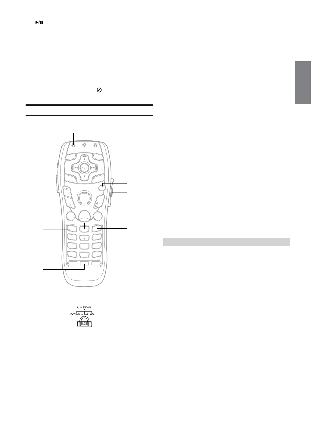
< Button
Performs playback.
Press and hold for at least 2 seconds for slow motion
playback.
= BAND Button
Switches the band of Audio or Disc mode.
> MODE Change Switch
When operating the connected DVD player/DVD changer,
switch to the EXT DVD side.
• Depending on the disc or playback status, certain operations
may not work. In this case, the mark is displayed on the
monitor screen.
Operating the Navigation (sold separately)
1
!
9
8
7
2
3
6
1 NAV. transmission indicator
The transmission indicator lights for a few seconds when
the mode selector switch is set to “NAV.”.
2 DTR (DETOUR) Button
Automatically recalculates route if a road block or traffic
congestion is encountered.
3 LIST Button
Displays list of the streets currently set for the route. To
return to the guidance mode, press the DISP button.
4 DEL. DEST. Button
Deletes current destination.
5 OK button
Executes numeral input and starts searching.
6 N/H Button
Toggles between North UP and Heading UP orientation.
7 CANC. Button
Cancels current display screen and switches back to
previous screen with menus.
8 SCALE UP/DN Buttons
9 VOICE Button
Initiates vocal instruction for next route maneuver or
repeats last instruction.
! MODE Button
Inputs numerals using the numeric keypad, DEL. and +10
buttons.
After pressing the MODE button, the following buttons will
be pressed while the status indicator is blinking: numerals
(0-9), DEL. and +10.
" MODE Change Switch
Sets this switch to the “NAV.” side to operate a connected
Alpine navigation system.
4
"
(Rear of the Remote Control)
5
Operating a separately sold TV monitor
• To operate a separately sold Alpine TV monitor, press the mode
change switch on the rear of the remote control unit. Operate while
the transmission indicator is blinking.
• Included remote control unit operation seal: Apply the seal for the
type of TV monitor you are using to the rear of the remote control
unit.
• Operation may differ or may not be possible for some
products. Also refer to the product’s operating instructions.
55-EN
Page 58
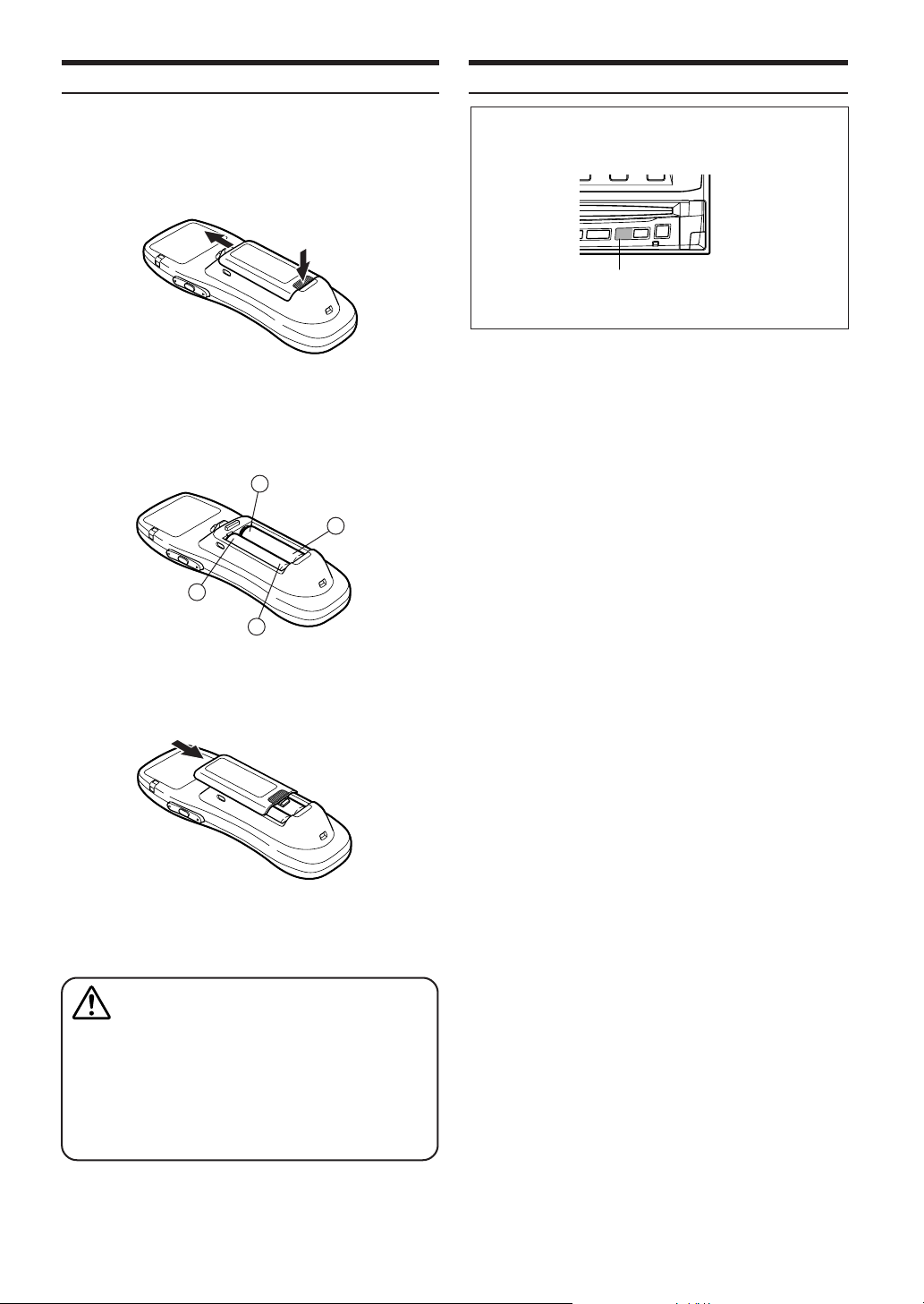
Battery Replacement
Notes on Using the Remote Control
Applicable battery: Use two “AAA” sized dry batteries or equivalent.
Opening the battery cover.
1
Push on the cover and slide it as indicated by the arrows
then the cover will be removed.
Replacing the battery.
2
Put the batteries in the case observing the polarity, as
illustrated.
−
+
+
−
Point the remote control transmitter at the remote control
sensor.
Remote control sensor
• Point the remote control at the remote sensor within about 2
meters.
• It may not be possible to operate the remote control unit if the
remote control sensor is exposed to direct sunlight.
• The remote control is a small, light weight precision device. To
avoid damage, short battery life, operational errors and poor
button response, observe the following.
− Do not subject to shock.
− Do not put in a trouser pocket.
− Keep away from food, moisture and dirt.
− Do not place in direct sunlight.
Closing the cover.
3
Push the cover in the arrow direction until a click is heard.
Warning
DO NOT OPERATE ANY FUNCTION THAT TAKES
YOUR ATTENTION AWAY FROM SAFELY DRIVING
YOUR VEHICLE.
Any function that requires your prolonged attention should
only be performed after coming to a complete stop. Always
stop the vehicle in a safe location before performing these
functions. Failure to do so may result in an accident.
56-EN
Page 59
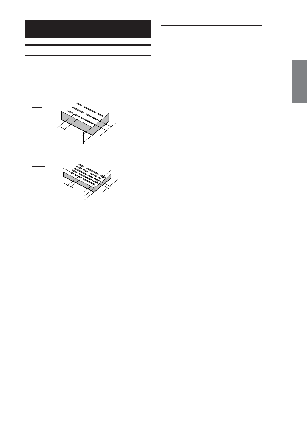
Information
About DVDs
Music CDs and DVDs have grooves (tracks) in which the
digital data is recorded. The data is represented as
microscopic pits recorded into the track – these pits are read
by a laser beam to play the disc. On DVDs, the density of the
tracks and pits is twice that of CDs, so DVDs can contain more
data in less space.
CDs
Minimum pit
length -
0.9 µm
DVDs
Minimum pit
length -
0.9 µm
1.2 mm
0.6 mm
0.6 mm
Track pitch -
1.6 µm
Track pitch -
0.74 µm
In addition, DVDs offer a variety of functions.
• Multiple audio* (page 18)
Movies can be recorded in up to eight languages. The
desired language can be selected from the remote control
unit.
• Subtitles function* (page 19)
Movies can include subtitles in up to 32 languages. The
desired subtitle language can be selected from the remote
control unit.
• Multi angle function* (page 18)
When the DVD contains a movie shot from multiple angles,
the desired angle can be selected from the remote control
unit.
• Multi story function*
With this function, a single movie includes various story
lines. You can select different story lines to view various
versions of the same movie.
Operation differs from disc to disc. Story line selection
screens including instructions appear during the movie.
Just follow the instructions.
* The functions audio languages, subtitle languages, angles, etc.,
differ from disc to disc. For details, refer to the disc’s instructions.
A 12 cm disc can contain one movie or about four hours of
music.
In addition, DVDs provide sharp picture quality with vivid colors
thanks to a horizontal resolution of over 500 lines (compared to less
than 300 for VHS tape). With the addition of an optional, digital audio
processor (PXA-H900/PXA-H510/PXA-H700), you can recreate the
power and presence of a movie theater with Dolby Digital 5.1-channel
Surround.
57-EN
Page 60
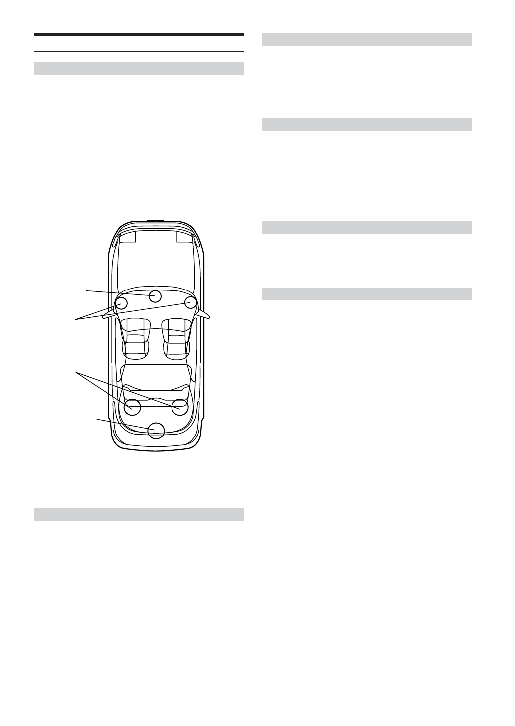
Terminology
Dolby Digital
Dolby Digital is a digital audio compression technology
developed by Dolby Laboratories that allows large quantities
of audio data to be efficiently recorded on discs. It is
compatible with audio signals from mono (1 channel) all the
way up to 5.1-channel surround sound. The signals for the
different channels are completely independent, and since the
sound is high quality digital there is no loss of sound quality.
* The separately sold digital audio processor (PXA-H510/PXA-
H900/PXA-H700) is required to enjoy full 5.1-channel surround
sound.
The IVA-D901 performs Dolby Digital decoding when it outputs
analog audio signals, it just happens to be 2-channel audio not
5.1-channel.
Center
speaker
Front
speakers
Rear
speakers
Dolby Pro Logic
Dolby Pro Logic is the technology used to decode programs
encoded in Dolby Surround. Pro logic decoding will provide
you with four channels of sound (front left/right, center and
monaural rear surround) from a 2-channel (stereo) source.
* The separately sold digital audio processor (PXA-H510/PXA-
H900) is required to enjoy Dolby Pro Logic surround sound.
Dolby Pro Logic II
Dolby Pro Logic II plays 2-channel sources in 5 channels over
the entire frequency range.
This is done with an advance, high sound quality matrix
surround decoder which draws out the spatial properties of the
original recording without adding any sounds to or changing
the sound of the source.
* The separately sold digital audio processor (PXA-H700) is
required to enjoy Dolby Pro Logic II surround sound.
Linear PCM audio (LPCM)
LPCM is a signal recording format used for music CDs.
Whereas music CDs are recorded at 44.1 kHz/16 bits, DVDs
are recorded at 48 kHz/16 bits to 96 kHz/24 bits, thereby
achieving higher sound quality than music CDs.
Rating levels (parental lock)
This is a function of the DVD for restricting the viewing age as
stipulated by laws in different countries. The way in which
viewing is restricted differs from DVD to DVD. Sometimes the
DVD cannot be played at all, other times certain scenes are
skipped, and other times certain scenes are replaced with
other scenes.
Subwoofer
Speaker layout for enjoying
Dolby Digital sound/dts sound
DTS
This is a home-use digital sound format of the DTS Sound
System. This is a high quality sound system, developed by
Digital Theater Systems Corp. for use in movie theaters.
DTS has six independent sound tracks. The theater
presentation is fully realized in the home and other settings.
DTS is the abbreviation for Digital Theater System.
*To enjoy DTS surround sound you need the separately sold DTS
digital audio processor (PXA-H900/PXA-H700). The DVD video
software must also have a DTS sound track.
The IVA-D901 has a built-in DTS 2-channel audio decoder.
Analog audio outputs are available.
58-EN
Page 61
List of Language Codes
(For details, see page 29.)
Abbreviation
AA
AB
AF
AM
AR
AS
AY
AZ
BA
BE
BG
BH
BI
BN
BO
BR
CA
CO
CS
CY
DA
DE
DZ
EL
EN
EO
ES
ET
EU
FA
FI
FJ
FO
FR
FY
GA
GD
GL
GN
GU
HA
HI
HR
HU
HY
IA
Code
6565
6566
6570
6577
6582
6583
6589
6590
6665
6669
6671
6672
6673
6678
6679
6682
6765
6779
6783
6789
6865
6869
6890
6976
6978
6979
6983
6984
6985
7065
7073
7074
7079
7082
7089
7165
7168
7176
7178
7185
7265
7273
7282
7285
7289
7365
Language
Afar
Abkhazian
Afrikaans
Amharic
Arabic
Assamese
Aymara
Azerbaijani
Bashkir
Byelorussian
Bulgarian
Bihari
Bislama
Bengali, Bangla
Tibetan
Breton
Catalan
Corsican
Czech
Welsh
Danish
German
Bhutani
Greek
English
Esperanto
Spanish
Estonian
Basque
Persian
Finnish
Fiji
Faroese
French
Frisian
Irish
Scots Gaelic
Galician
Guarani
Gujarati
Hausa
Hindi
Croatian
Hungarian
Armenian
Interlingua
Abbreviation
IE
IK
IN
IS
IT
IW
JA
JI
JW
KA
KK
KL
KM
KN
KO
KS
KU
KY
LA
LN
LO
LT
LV
MG
MI
MK
ML
MN
MO
MR
MS
MT
MY
NA
NE
NL
NO
OC
OM
OR
PA
PL
PS
PT
QU
RM
Code
7369
7375
7378
7383
7384
7387
7465
7473
7487
7565
7575
7576
7577
7578
7579
7583
7585
7589
7665
7678
7679
7684
7686
7771
7773
7775
7776
7778
7779
7782
7783
7784
7789
7865
7869
7876
7879
7967
7977
7982
8065
8076
8083
8084
8185
8277
Language
Interlingue
Inupiak
Indonesian
Icelandic
Italian
Hebrew
Japanese
Yiddish
Javanese
Georgian
Kazakh
Greenlandic
Cambodian
Kannada
Korean
Kashmiri
Kurdish
Kirghiz
Latin
Lingala
Laothian
Lithuanian
Latvian, Lettish
Malagasy
Maori
Macedonian
Malayalam
Mongolian
Moldavian
Marathi
Malay
Maltese
Burmese
Nauru
Nepali
Dutch
Norwegian
Occitan
(Afan) Oromo
Oriya
Punjabi
Polish
Pashto, Pushto
Por tuguese
Quechua
Rhaeto-Romance
Abbreviation
RN
RO
RU
RW
SA
SD
SG
SH
SI
SK
SL
SM
SN
SO
SQ
SR
SS
ST
SU
SV
SW
TA
TE
TG
TH
TI
TK
TL
TN
TO
TR
TS
TT
TW
UK
UR
UZ
VI
VO
WO
XH
YO
ZH
ZU
Code
8278
8279
8285
8287
8365
8368
8371
8372
8373
8375
8376
8377
8378
8379
8381
8382
8383
8384
8385
8386
8387
8465
8469
8471
8472
8473
8475
8476
8478
8479
8482
8483
8484
8487
8575
8582
8590
8673
8679
8779
8872
8979
9072
9085
Language
Kirundi
Romanian
Russian
Kinyarwanda
Sanskrit
Sindhi
Sangho
Serbo-Croatian
Singhalese
Slovak
Slovenian
Samoan
Shona
Somali
Albanian
Serbian
Siswati
Sesotho
Sundanese
Swedish
Swahili
Tamil
Telugu
Tajik
Thai
Tigrinya
Tu rk m en
Tagalog
Setswana
Tonga
Tu rkish
Tsonga
Tatar
Tw i
Ukrainian
Urdu
Uzbek
Vietnamese
Volapuk
Wolof
Xhosa
Yo r uba
Chinese
Zulu
59-EN
Page 62
List of Country Codes
(For details, see page 29.)
Abbreviation
AD
AE
AF
AG
AI
AL
AM
AN
AO
AQ
AR
AS
AT
AU
AW
AZ
BA
BB
BD
BE
BF
BG
BH
BI
BJ
BM
BN
BO
BR
BS
BT
BV
BW
BY
BZ
CA
CC
CD
CF
CG
CH
CI
CK
CL
CM
CN
CO
CR
CU
CV
CX
CY
CZ
DE
DJ
DK
Code
Andorra
6568
United Arab Emirates
6569
Afghanistan
6570
Antigua and Barbuda
6571
Anguilla
6573
Albania
6576
Armenia
6577
Netherlands Antilles
6578
Angola
6579
Antarctica
6581
Argentina
6582
American Samoa
6583
Austria
6584
Australia
6585
Aruba
6587
Azerbaijan
6590
Bosnia and Herzegovina
6665
Barbados
6666
Bangladesh
6668
Belgium
6669
Burkina Faso
6670
Bulgaria
6671
Bahrain
6672
Burundi
6673
Benin
6674
Bermuda
6677
Brunei Darussalam
6678
Bolivia
6679
Brazil
6682
Bahamas
6683
Bhutan
6684
Bouvet Island
6686
Botswana
6687
Belarus
6689
Belize
6690
Canada
6765
Cocos (Keeling) Islands
6767
Congo, the Democratic
6768
Republic of the
Central African Republic
6770
Congo
6771
Switzerland
6772
Cote d’lvoire
6773
Cook Islands
6775
Chile
6776
Cameroon
6777
China
6778
Colombia
6779
Costa Rica
6782
Cuba
6785
Cape Verde
6786
Christmas Island
6788
Cyprus
6789
Czech Republic
6790
Germany
6869
Djibouti
6874
Denmark
6875
Country
DM
DO
DZ
EC
EE
EG
EH
ER
ES
ET
FI
FJ
FK
FM
FO
FR
GA
GB
GD
GE
GF
GH
GI
GL
GM
GN
GP
GQ
GR
GS
GT
GU
GW
GY
HK
HM
HN
HR
HT
HU
ID
IE
IL
IN
IO
IQ
IR
IS
IT
JM
JO
JP
KE
KG
KH
6877
6879
6890
6967
6969
6971
6972
6982
6983
6984
7073
7074
7075
7077
7079
7082
7165
7166
7168
7169
7170
7172
7173
7176
7177
7178
7180
7181
7182
7183
7184
7185
7187
7189
7275
7277
7278
7282
7284
7285
7368
7369
7376
7378
7379
7381
7382
7383
7384
7477
7479
7480
7569
7571
7572
Country CountryCode CodeAbbreviation Abbreviation
Dominica
Dominican Republic
Algeria
Ecuador
Estonia
Egypt
Western Sahara
Eritrea
Spain
Ethiopia
Finland
Fiji
Falkland Islands
Micronesia, Federated States of
Faroe Islands
France
Gabon
United Kingdom
Grenada
Georgia
French Guiana
Ghana
Gibraltar
Greenland
Gambia
Guinea
Guadeloupe
Equatorial Guinea
Greece
South Georgia and the
South Sandwich Islands
Guatemala
Guam
Guinea-Bissau
Guyana
Hong Kong
Heard Island and
McDonald Islands
Honduras
Croatia
Haiti
Hungary
Indonesia
Ireland
Israel
India
British Indian Ocean Territory
Iraq
Iran, Islamic Republic of
Iceland
Italy
Jamaica
Jordan
Japan
Kenya
Kyrgyzstan
Cambodia
KI
KM
KN
KP
KR
KW
KY
KZ
LA
LB
LC
LI
LK
LR
LS
LT
LU
LV
LY
MA
MC
MD
MG
MH
MK
ML
MM
MN
MO
MP
MQ
MR
MS
MT
MU
MV
MW
MX
MY
MZ
NA
NC
NE
NF
NG
NI
NL
NO
NP
NR
NU
NZ
OM
PA
7573
Kiribati
7577
Comoros
7578
Saint Kitts and Nevis
7580
Korea, Democratic
People’s Republic of
7582
Korea, Republic of
7587
Kuwait
7589
Cayman Islands
7590
Kazakstan
7665
Lao People’s
Democratic Republic
7666
Lebanon
7667
Saint Lucia
7673
Liechtenstein
7675
Sri Lanka
7682
Liberia
7683
Lesotho
7684
Lithuania
7685
Luxembourg
7686
Latvia
7689
Libyan Arab Jamahiriya
7765
Morocco
7767
Monaco
7768
Moldova, Republic of
7771
Madagascar
7772
Marshall Islands
7775
Macedonia, The former
Yugoslav Republic of
7776
Mali
7777
Myanmar
7778
Mongolia
7779
Macau
7780
Northern Mariana Islands
7781
Martinique
7782
Mauritania
7783
Montserrat
7784
Malta
7785
Mauritius
7786
Maldives
7787
Malawi
7788
Mexico
7789
Malaysia
7790
Mozambique
7865
Namibia
7867
New Caledonia
7869
Niger
7870
Norfolk Island
7871
Nigeria
7873
Nicaragua
7876
Netherlands
7879
Norway
7880
Nepal
7882
Nauru
7885
Niue
7890
New Zealand
7977
Oman
8065
Panama
60-EN
Page 63
Abbreviation
PE
PF
PG
PH
PK
PL
PM
PN
PR
PT
PW
PY
QA
RE
RO
RU
RW
SA
SB
SC
SD
SE
SG
SH
SI
Country
Peru
8069
French Polynesia
8070
Papua New Guinea
8071
Philippines
8072
Pakistan
8075
Poland
8076
Saint Pierre and Miquelon
8077
Pitcairn
8078
Puerto Rico
8082
Por tugal
8084
Palau
8087
Paraguay
8089
Qatar
8165
Reunion
8269
Romania
8279
Russian Federation
8285
Rwanda
8287
Saudi Arabia
8365
Solomon Islands
8366
Seychelles
8367
Sudan
8368
Sweden
8369
Singapore
8371
Saint Helena
8372
Slovenia
8373
Abbreviation CountryCode
SJ
SK
SL
SM
SN
SO
SR
ST
SV
SY
SZ
TC
TD
TF
TG
TH
TJ
TK
TM
TN
TO
TP
TR
TT
TV
Code
Svalbard and Jan Mayen
8374
Slovakia
8375
Sierra Leone
8376
San Marino
8377
Senegal
8378
Somalia
8379
Suriname
8382
Sao Tome and Principe
8384
El Salvador
8386
Syrian Arab Republic
8389
Swaziland
8390
Tu r ks and Caicos Islands
8467
Chad
8468
French Southern Territories
8470
Togo
8471
Thailand
8472
Tajikistan
8474
To ke l a u
8475
Tu rkmenistan
8477
Tunisia
8478
Tonga
8479
East Timor
8480
Tu r ke y
8482
Tr inidad and Tobago
8484
Tu va l u
8486
CountryCode
Abbreviation
TW
TZ
UA
UG
UM
US
UY
UZ
VA
VC
VE
VG
VI
VN
VU
WF
WS
YE
YT
YU
ZA
ZM
ZW
8487
8490
8565
8571
8577
8583
8589
8590
8665
8667
8669
8671
8673
8678
8685
8770
8783
8969
8984
8985
9065
9077
9087
Taiwan, Province of China
Tanzania, United Republic of
Ukraine
Uganda
United States Minor
Outlying Islands
United States
Uruguay
Uzbekistan
Holy See (Vatican City State)
Saint Vincent and the
Grenadines
Venezuela
Virgin Island, British
Virgin Islands, U.S
Viet Nam
Van uatu
Wallis and Futuna
Samoa
Ye m e n
Mayotte
Yugoslavia
South Africa
Zambia
Zimbabwe
61-EN
Page 64

In Case of Difficulty
If you encounter a problem, please turn the power off, then on
again. If the unit is still not functioning normally, please review
the items in the following checklist. This guide will help you
isolate the problem if the unit is at fault. Otherwise, make sure the
rest of your system is properly connected, or then consult your
authorized Alpine dealer.
Basic
No function or display.
• Vehicle's ignition is off.
- If connected according to the instructions, the unit will not
operate with the vehicle's ignition off.
• Improper power lead connections.
-Check power lead connections.
• Blown fuse.
-Check the fuse on the battery lead of the unit; replace
with the proper value if necessary.
• Internal micro-computer malfunctioned due to interference
noise, etc.
-Press the RESET switch with a ballpoint pen or other
pointed article.
No sound or unnatural sound.
• Incorrect setting of volume/balance/fader controls.
-Readjust the controls.
• Connections are not properly or securely made.
-Check the connections and firmly connect.
Screen not displayed.
• Brightness control is set at the minimum position.
-Adjust the Brightness control.
• Temperature in the vehicle is too low.
- Increase the vehicle's interior temperature to operation
temperature range.
• Connections to the DVD, CD player, navigation system are not
securely made.
-Check the connections and firmly connect.
Movement of displayed picture is abnormal.
• Temperature in the vehicle is too high.
-Allow the vehicle's interior temperature to cool.
Unclear or noisy display.
• Fluorescent plate is worn out.
-Replace the fluorescent plate.
Navigation system inoperative.
• Connections to the navigation system are incorrect.
-Check the connections with the navigation system and
connect the cables correctly and firmly.
Unclear picture display.
• Fluorescent tube is exhausted.
-Replace the fluorescent tube*.
* The fluorescent tube replacement is not free of charge even within
the warranty period, for the tube is an article of consumption.
Radio
Unable to receive stations.
• No antenna, or open connection in the antenna cable.
-Make sure the antenna is properly connected;
replace the antenna or cable if necessary.
Unable to tune stations in the seek mode.
• You are in a weak signal area.
-Make sure the tuner is in DX mode.
• If the area you are in is a primary signal area, the antenna may
not be grounded and connected properly.
-Check your antenna connections; make sure the antenna is
properly grounded at its mounting location.
• The antenna may not be the proper length.
-Make sure the antenna is fully extended; if broken, replace
the antenna with a new one.
Broadcast is noisy.
• The antenna is not the proper length.
-Extend the antenna fully; replace it if it is broken.
• The antenna is poorly grounded.
-Make sure the antenna is grounded properly at its mounting
location.
• The station signal is weak and noisy.
- If above solution does not work, tune in another station.
CD/MP3/DVD/Video CD
Disc playback sound is wavering.
• Moisture condensation in the disc Module.
-Allow enough time for the condensation to evaporate
(about 1 hour).
Disc insertion not possible.
• A disc is already in the DVD player.
-Eject the disc and remove it.
• The disc is being improperly inserted.
-Make sure the disc is being inserted following the
instructions in the CD (MP3/DVD/Video CD) Player
Operation section.
Unable to fast forward or backward the disc.
• The disc has been damaged.
-Eject the disc and discard it; using a damaged disc in
your unit can cause damage to the mechanism.
Disc playback sound skips due to vibration.
• Improper mounting of the unit.
-Securely re-mount the unit.
• Disc is very dirty.
-Clean the disc.
• Disc has scratches.
-Change the disc.
• The pick-up lens is dirty.
-Do not use a commercial available lens cleaner disc.
Consult your nearest ALPINE dealer.
Disc playback sound skips without vibration.
• Dirty or scratched disc.
-Clean the disc; damaged disc should be replaced.
CD-R/CD-RW playback not possible.
• Close session (finalization) has not been performed.
- Perform finalization and attempt playback again.
62-EN
Page 65
Error displays
• Mechanical error
-Press c. After the error indication disappears, insert the disc
again. If the above-mentioned solution does not solve the
problem, consult your nearest ALPINE dealer.
MP3 is not played back.
• Writing error occurred. The CD format is not compatible.
- Make sure the CD has been written in a supported format.
Refer to "About MP3" (pages 13 and 14), then rewrite in the
format supported by this device.
Unit does operate.
• Monitor’s power is not turned on.
-Turn on the monitor’s power.
• Condensation.
-Wait a while (about 1 hour) for the condensation to dry.
No picture is produced.
• Monitor’s mode is not switched to the mode you want to see.
- Switch to the mode you want to see.
• Monitor’s parking brake lead is not connected.
- Connect the monitor’s parking brake lead and set the parking
brake.
(For details, refer to the monitor’s instructions.)
• Monitor’s parking brake is not set.
- Connect the monitor’s parking brake lead and set the parking
brake.
(For details, refer to the monitor’s instructions.)
Playback does not start.
• Disc is loaded upside-down.
- Check the disc and load it with the labeled side facing
upward.
• Disc is dirty.
-Clean the disc.
• A disc not able to playback with this unit is loaded.
- Check if the disc is able to be played back.
• Parental lock is set.
-Cancel the parental lock or change the rating level.
Picture is unclear or noisy.
• Disc is being fast-forwarded or fast-reversed.
- The picture may be slightly disturbed, but this is normal.
• Ve hicle’s battery power is weak.
- Check the battery power and wiring.
(The unit may malfunction if the battery power is under 11
volts with a load applied.)
• Monitor’s fluorescent tube is worn.
-Replace the monitor’s fluorescent tube.
Image stops sometimes.
• Disc is scratched.
-Replaced with a non-scratched disc.
Indication for CD/MP3
HI-TEMP
• Protective circuit is activated due to high temperature.
-The indicator will disappear when the temperature returns to
within operation range.
-Leave the power OFF until the temperature decreases and
then turn the power ON again.
NO DISC
• No disc is inserted.
- Insert a disc.
• Although a disc is inserted, “NO DISC” is displayed and the
unit does not start to play or eject the disc.
-Remove the disc by following these steps:
Press c for at least 3 seconds.
Continued
63-EN
Page 66
Indication for DVD/Video CD
NO DISC
• No disc is inserted.
- Insert a disc.
• Although a disc is inserted, “NO DISC” is displayed and the
unit does not start to play or eject the disc.
-Remove the disc by following these steps:
Press c for at least 3 seconds.
(Displayed only in IVA-D901 (front
monitor))
LOADING ERROR
EJECT ERROR
•Mechanism error.
1) Press c and eject the disc.
If not ejecting, consult your Alpine dealer.
2) When the error indication remains after ejecting, press
c again.
If the error indication still does not turn off after pressing
c for a few times, consult your Alpine dealer.
(Displayed in the rear monitor)
(Displayed in the rear monitor)
• Remote control operation is not possible.
-For some discs or playing modes, certain operations are not
possible. This is not a malfunction.
HI-TEMP
• Protective circuit is activated to high temperature.
- The indicator will disappear when the temperature
returns to within operation range.
-Leave the power OFF until the temperature decreases and
then turn the power ON again.
VIDEO SIGNAL SYSTEM IS
NOT CORRECT
• PAL disc is loaded.
- Load an NTSC disc
DISC ERROR
•Scratched disc, contaminated disc/poor recording/disc
incompatible with this unit
-Press c.
-Change the disc.
(Displayed in the rear monitor)
64-EN
Page 67
Indication for CD changer
Indication for XM radio mode
HI-TEMP
•Protective circuit is activated due to high temperature.
- The indicator will disappear when the temperature
returns to within operation range.
ERROR - 01
•Malfunction in the CD Changer.
- Consult your Alpine dealer. Press the magazine eject
button and pull out the magazine.
Check the indication. Insert the magazine again.
If the magazine cannot be pulled out, consult your Alpine
dealer.
•Magazine ejection not possible.
-Press the magazine eject button. If the magazine does
not eject, consult your Alpine dealer.
ERROR - 02
•A disc is left inside the CD Changer.
-Press the Eject button to activate the eject function. When the
CD Changer finishes the eject function, insert an empty CD
magazine into the CD Changer to receive the disc left inside
the CD Changer.
NO MAGZINE
ANTENNA
•The XM antenna is not connected to the XM radio module.
-Check whether the XM antenna cable is attached securely to
the XM radio module.
UPDATING
•Radio is being updated with latest encryption code.
-Wait until encryption code is being updated. Channels
0 and 1 should function normally.
NO SIGNAL
• XM signal is too weak at the current location.
-Wait until the car reaches a location with a stronger signal.
LOADING
•Radio is acquiring audio or program information.
-Wait until the radio has received the information.
OFF AIR
•The channel currently selected has stopped broadcasting.
-Select another channel.
• No magazine is loaded into the CD Changer.
- Insert a magazine.
NO DISC
• No indicated disc.
- Choose another disc.
– – – – – –
•The user has selected a Channel Number that does not exist or
is not subscribed to.
-The unit will revert back to the previously selected channel.
•There is no artist name/feature, song/program title, or
additional information associated with the channel at that time.
-No action needed.
65-EN
Page 68

Specifications
MONITOR SECTION
Screen Size 7.0"
LCD Type Transparent type TN LCD
Operation System Low-Temperature p-si TFT active
matrix
Number of Picture Elements 1,152,000 pcs. (2,400 × 480)
Effective Number of Picture Elements
99.99% or more
Illumination System Cold cathode fluorescent tube
FM TUNER SECTION
Tuning Range 87.7 – 107.9 MHz
Mono Usable Sensitivity 9.3 dBf (0.8 µV/75 ohms)
50 dB Quieting Sensitivity 13.5 dBf (1.3 µV/75 ohms)
Alternate Channel Selectivity 80 dB
Signal-to-Noise Ratio 80 dB
Stereo Separation 45 dB
Capture Ratio 2.0 dB
AM TUNER SECTION
Tuning Range 530 – 1,710 kHz
Usable Sensitivity 22.5 µV/27.0 dB
CD/DVD SECTION
Frequency Response 5 – 20,000 Hz
Wow & Flutter (% WRMS) Below measurable limits
Total Harmonic Distortion 0.008% (at 1 kHz)
Dynamic Range 95 dB (at 1 kHz)
Channel Separation 85 dB (at 1 kHz)
Signal system NTSC
Horizontal resolution 500 lines or greater
Video output level 1Vp-p (75 ohms)
Video S/N ratio DVD: 60 dB
Audio S/N ratio More than 105 dB
PICKUP
Wave length 668 nm
Laser power CLASS II
REMOTE CONTROL
Battery Type AAA batteries (2 pcs.)
Width 56 mm (2-1/4")
Height 142.5 mm (5-5/8")
Depth 37 mm (1-7/16")
Weight 72 g (2.54 oz)
Power Requirement 14.4 V DC
(11–16 V allowable)
Operating temperature +32°F to +113°F
(0°C to + 45°C)
Power Output 18 W RMS × 4*
*Primary amplifier ratings per CEA-2006 Standard
•Power output: measured at 4 Ohms and ≤ 1% THD+N
•S/N: 80 dBA (reference: 1 W into 4 Ohms)
Output Voltage 2,000 mV/10k ohms
Maximum Pre-Output Voltage
4 V/10k ohms
Bass ±14 dB at 30 Hz
Treble ±14 dB at 10 kHz
Weight (Monitor Section) 1.7 kg
(3 lbs. 12 oz)
(Tuner Section) 1.6 kg
(3 lbs. 8 oz)
Audio output level
Preout (Front, Rear): 4V/10k ohms (max.)
Preout (Subwoofer): 4V/10k ohms (max.)
Auxout: 1.2V/10k ohms
Ai-NET: 850 mV
CHASSIS SIZE (Monitor section)
Width 178 mm (7")
Height 50 mm (2")
Depth 165 mm (6-1/2")
CHASSIS SIZE (Tuner section)
Width 275 mm (10-53/64")
Height 40 mm (1-37/64")
Depth 170 mm (6-11/16")
• Due to continuous product improvement, specifications and design
are subject to change without notice.
• The LCD panel is manufactured using an extremely high precision
manufacturing technology. Its effective pixel ratio is over 99.99%.
This means that there is a possibility that 0.01% of the pixels could
be either always ON or OFF.
CAUTION
CAUTION-Laser radiation when open, DO NOT STARE INTO BEAM
(Bottom side of Monitor player)
GENERAL
66-EN
Page 69
Installation and Connections
Before installing or connecting the unit, please read the
following and pages 4 to 6 of this manual thoroughly
for proper use.
Warning
MAKE THE CORRECT CONNECTIONS
Failure to make the proper connections may result in fire or
product damage.
USE ONLY IN CARS WITH A 12 VOLT NEGATIVE GROUND.
(Check with your dealer if you are not sure.) Failure to do so may
result in fire, etc.
BEFORE WIRING, DISCONNECT THE CABLE FROM THE
NEGATIVE BATTERY TERMINAL.
Failure to do so may result in electric shock or injury due to
electrical shorts.
DO NOT ALLOW CABLES TO BECOME ENTANGLED IN
SURROUNDING OBJECTS.
Arrange wiring and cables in compliance with the manual to
prevent obstructions when driving. Cables or wiring that obstruct
or hang up on places such as the steering wheel, gear lever, brake
pedals, etc. can be extremely hazardous.
DO NOT SPLICE INTO ELECTRICAL CABLES.
Never cut away cable insulation to supply power to other
equipment. Doing so will exceed the current carrying capacity of
the wire and result in fire or electric shock.
DO NOT DAMAGE PIPE OR WIRING WHEN DRILLING
HOLES.
When drilling holes in the chassis for installation, take
precautions so as not to contact, damage or obstruct pipes, fuel
lines, tanks or electrical wiring. Failure to take such precautions
may result in fire.
DO NOT USE BOLTS OR NUTS IN THE BRAKE OR
STEERING SYSTEMS TO MAKE GROUND CONNECTIONS.
Bolts or nuts used for the brake or steering systems (or any other
safety-related system), or tanks should NEVER be used for
installations or ground connections. Using such parts could
disable control of the vehicle and cause fire etc.
KEEP SMALL OBJECTS SUCH AS BOLTS OR SCREWS OUT
OF THE REACH OF CHILDREN.
Swallowing them may result in serious injury. If swallowed,
consult a physician immediately.
DO NOT INSTALL IN LOCATIONS WHICH MIGHT HINDER
VEHICLE OPERATION, SUCH AS THE STEERING WHEEL
OR GEARSHIFT.
Doing so may obstruct forward vision or hamper movement etc.
and results in serious accident.
Caution
HAVE THE WIRING AND INSTALLATION DONE BY
EXPERTS.
The wiring and installation of this unit requires special technical
skill and experience. To ensure safety, always contact the dealer
where you purchased this product to have the work done.
USE SPECIFIED ACCESSORY PARTS AND INSTALL THEM
SECURELY.
Be sure to use only the specified accessory parts. Use of other
than designated parts may damage this unit internally or may not
securely install the unit in place. This may cause parts to become
loose resulting in hazards or product failure.
ARRANGE THE WIRING SO IT IS NOT CRIMPED OR
PINCHED BY A SHARP METAL EDGE.
Route the cables and wiring away from moving parts (like the
seat rails) or sharp or pointed edges. This will prevent crimping
and damage to the wiring. If wiring passes through a hole in
metal, use a rubber grommet to prevent the wires insulation from
being cut by the metal edge of the hole.
DO NOT INSTALL IN LOCATIONS WITH HIGH MOISTURE
OR DUST.
Avoid installing the unit in locations with high incidence of
moisture or dust. Moisture or dust that penetrates into this unit
may result in product failure.
Precautions
• Be sure to disconnect the cable from the (–) battery post before
installing your IVA-D901. This will reduce any chance of
damage to the unit in case of a short-circuit.
• Be sure to connect the color coded leads according to the
diagram. Incorrect connections may cause the unit to
malfunction or damage to the vehicle's electrical system.
• When making connections to the vehicle's electrical system, be
aware of the factory installed components (e.g. on-board
computer). Do not tap into these leads to provide power for this
unit. When connecting the IVA-D901 to the fuse box, make
sure the fuse for the intended circuit of the IVA-D901 has the
appropriate amperage. Failure to do so may result in damage to
the unit and/or the vehicle. When in doubt, consult your
ALPINE dealer.
• The IVA-D901 uses female RCA-type jacks for connection to
other units (e.g. amplifier) having RCA connectors. You may
need an adaptor to connect other units. If so, please contact
your authorized ALPINE dealer for assistance.
• Be sure to connect the speaker (–) leads to the speaker (–)
terminal. Never connect left and right channel speaker cables to
each other or to the vehicle body.
• The Display must be completely retracted in the casing when
installing. If it is not, problems may occur.
• When installing in automobiles, make sure the Display can
open/close without coming in contact with the gear shift .
IMPORTANT
Please record the serial number of your unit in the space provided
below and keep it as a permanent record. The serial number plate is
located on the bottom of the unit.
SERIAL NUMBER:
INSTALLATION DATE:
INSTALLATION TECHNICIAN:
PLACE OF PURCHASE:
67-EN
Page 70
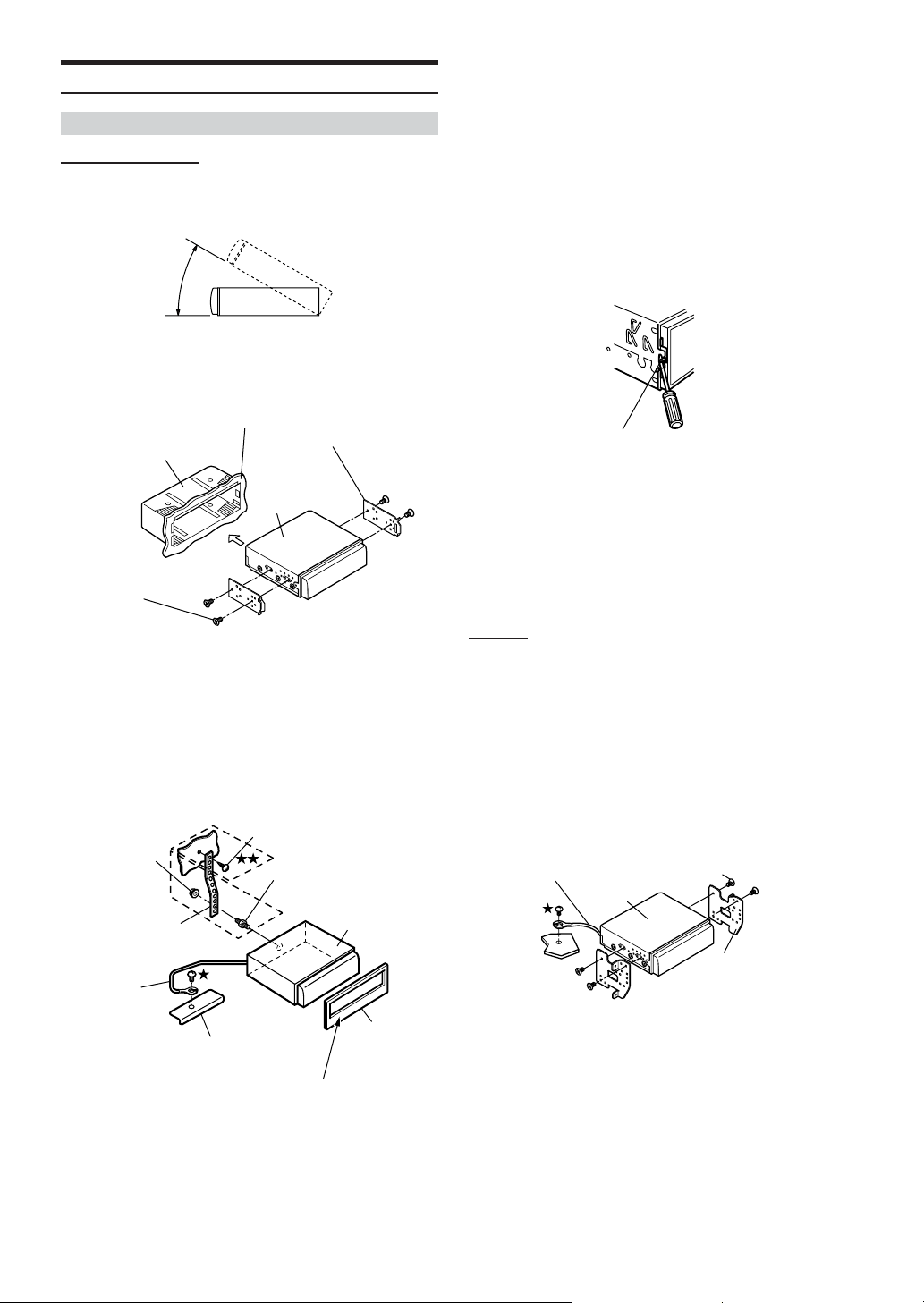
Installation
Installing the Monitor
Installation Location
Before deciding on the mounting location, check that opening and
closing the display will not hamper gear shifting in that position.
•Install at an angle of within 30 degrees from the horizontal.
1
Dashboard
Mounting Sleeve
(Included)
Mounting Bracket
(Included)
Reinforce the monitor unit with a metal mounting strap (not
supplied). Secure the ground lead of the unit to a clean
metal spot using a screw (}) already attached to the
vehicle's chassis.
•For the screw marked }}, use an appropriate screw for the
chosen mounting location.
Connect each input lead coming from an amplifier or
equalizer to the corresponding output lead coming from
the left rear of the IVA-D901. Connect all other leads of the
IVA-D901 according to details described in the
Connections section.
3
Lock Pin
IVA-D901
Screws (M4 x 3)
(Included)
Slide the mounting sleeve into the dashboard. Install the
supplied bracket on the monitor.
• Make sure to use the supplied screw (M4 x 3) to install the
monitor.
If you use another screw to install the monitor, it may cause a
malfunction.
2
Screw
Hex Nut (M5)
Bolt Stud
Metal Mounting
Strap
Ground
Lead
Chassis
Wider edge should face down.
IVA-D901
Front Frame
(Included)
Slide the IVA-D901 into the dashboard. When the unit is in
place, make sure the locking pins are fully seated in the
down position. This can be done by pressing firmly in on
the unit while pushing the locking pin down with a small
screwdriver. This ensures that the unit is properly locked
and will not accidentally come out from the dashboard.
Install the supplied Front Frame.
Removal
1. Use a small screwdriver (or similar tool) to push the
locking pins to the "up" position (see Step 3). As each
pin is unlocked, gently pull out on the unit to make sure
it does not re-lock before unlocking the second pin.
2. Pull the unit out, keeping it unlocked as you do so.
< JAPANESE CAR >
To install using the vehicle's standard bracket.
Screws (M4 x 6)
Ground Lead
IVA-D901
• Make sure to use the supplied screw (M4 x 6) to install the
monitor.
If you use another screw to install the monitor, it may cause a
malfunction.
(Included)
Mounting Bracket
68-EN
Page 71
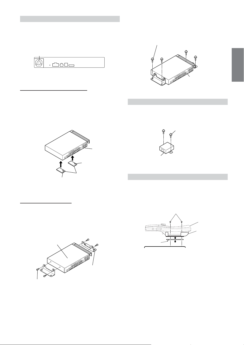
Installing the Tuner Box
Caution
Do not block the unit’s fan or heat sink, thus
preventing air circulation. If blocked, heat will
accumulate inside the unit and may cause a fire.
Air ventilation hole
<Side of the tuner box>
When mounting with Velcro fasteners
When mounting the tuner with the Velcro fasteners, be sure to choose
a flat location.
Do not hang the unit from the bottom of the dashboard or rear deck
with the Velcro fasteners.
Remove the Protective paper and attach two pieces
1
of Velcro fastener to the bottom of the Tuner.
Tuner Box
Install the tuner on the floor with the supplied
2
flange-head tapping screws (M4 x 14).
Flange-head tapping screws
(M4 x 14) (Included)
Tuner Box
Installing the DC/DC Converter
Install the DC/DC Converter on the floor with the
supplied flange-head tapping screws (M4 x 14).
Flange-head tapping
screws (M4 x 14) (Included)
Protective paper
Velcro Fasteners
Protective paper
Check the position, and then fix the Tuner to the
2
floor carpet.
When mounting with Screws
When mounting the tuner with the screws, be sure to choose a flat
location.
When making holes, be careful not to scratch any pipes or wires.
Connect the bracket to both the flanks of the tuner
1
with the supplied pan screws (M4 x 8).
Tuner Box
Pan screws (M4 x 8) (Included)
(Included)
Bracket (Included)
DC/DC Converter
Mounting the remote control holder
• If the remote control is in direct sunlight, remove it from the
holder and keep it in the glove box.
• When the holder cannot be mounted securely with Velcro
tape, mount it by using screws.
Reinforcement Screws
Remote Control
Remote Control
Holder
Protective paper
Console Box etc.
69-EN
Page 72
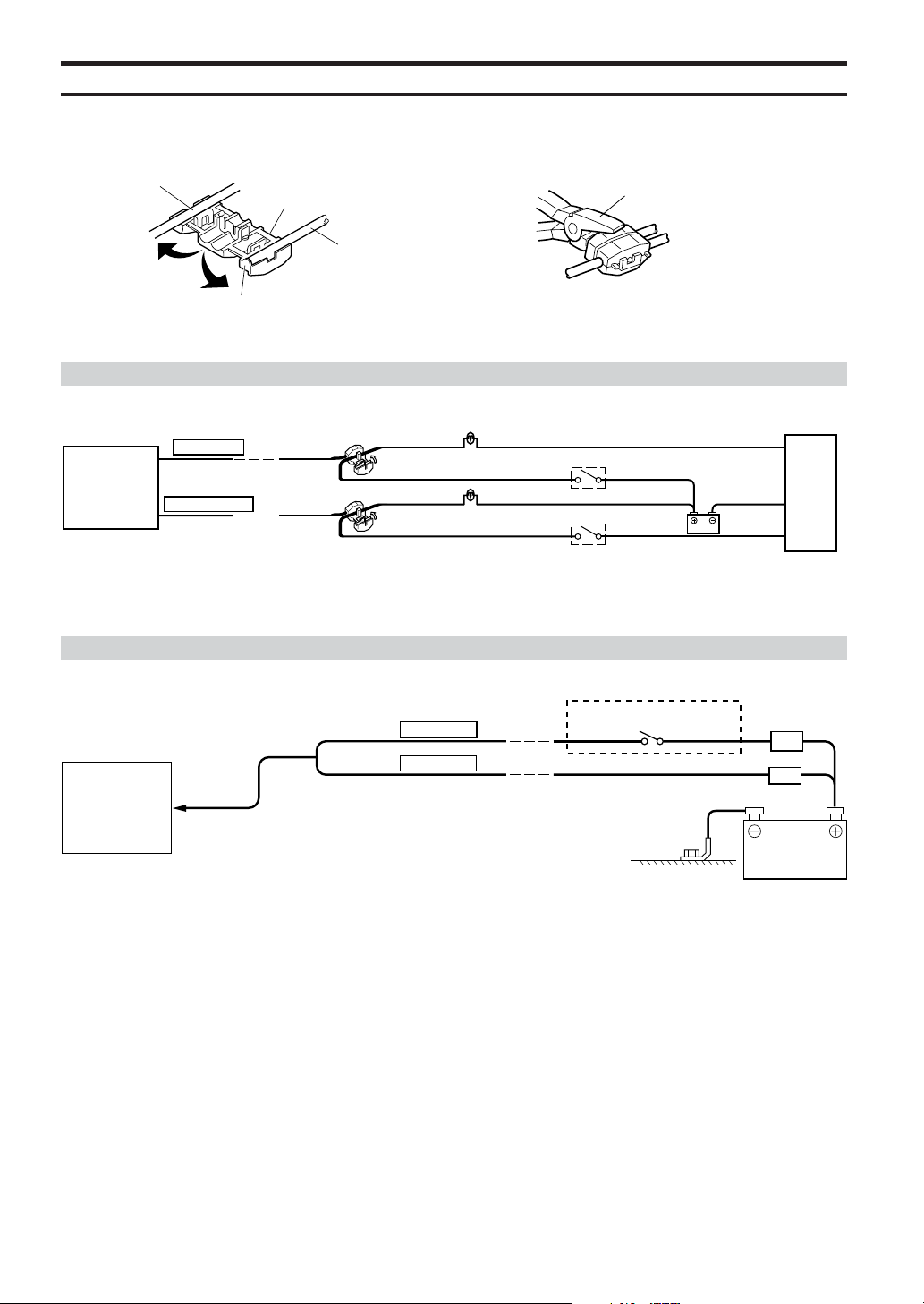
Parking Brake Lead Connection
If necessary, use a pinch connector to connect the foot brake lead, parking brake lead, etc.
12
Vehicle Cable
Pinch Connector
Stopper
Pliers
Monitor Cable
Foot Brake Lead / Parking Brake Lead Connection
Foot brake lamp
Foot brake switch
Chassis
Battery
Parking brake switch
IVA-D901
Tuner Box
FOOT BRAKE
(Yellow/Black)
PARKING BRAKE
(Yellow/Blue)
Pinch
Connector
Pinch
Connector
Foot brake lead
Parking brake lamp
Parking brake lead
Connection Diagram of SPST Switch (Sold Separately)
(If the ACC power supply is not available)
FUSE (5A)
(Optional)
Battery
IVA-D901
(Monitor and
Tuner Box)
(Red)
(Yellow)
IGNITION
BATTERY
SPST SW (Optional)
FUSE (25A) (Optional)
• If your vehicle has no ACC power supply, add an SPST (Single-Pole, Single-Throw) switch (sold separately) and fuse (sold separately).
• The diagram and the fuse amperage shown above are in the case when IVA-D901 is used individually.
• If the switched power (ignition) lead of the IVA-D901 is connected directly to the positive (+) post of the vehicle‘s battery, the IVA-D901 draws
some current (several hundred milliamperes) even when its switch is placed in the OFF position and the battery may be discharged.
70-EN
Page 73
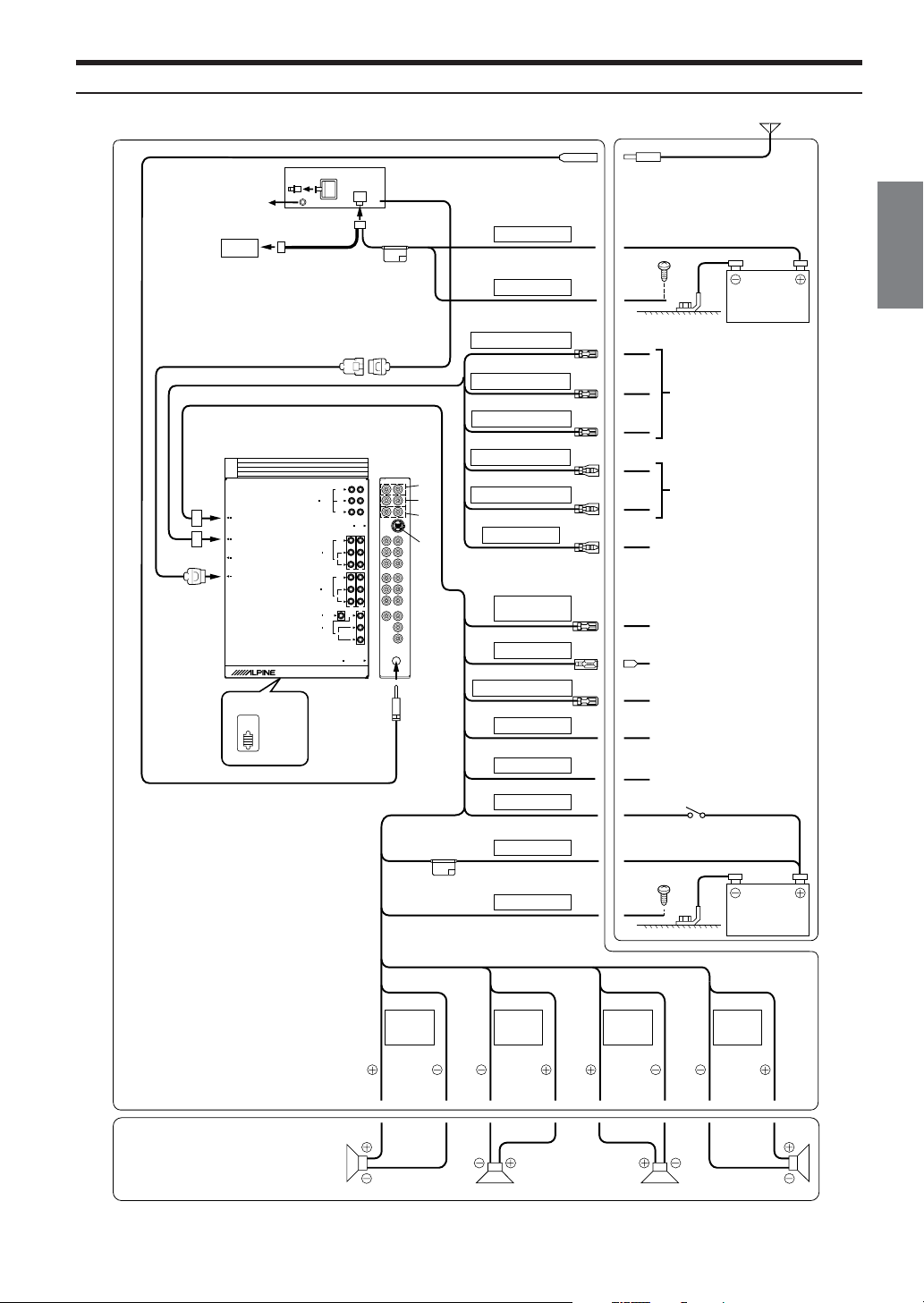
Connections (IVA-D901 Wiring Diagram)
Antenna
To remote control
interface box
5
IVA-D901
Tuner BOX
4
POWER SUPPLY
REMOTE IN/OUT
NAVIGATION IN
$
DISPLAY OUT
#
(
\
EQ/DIV
NORM
3
2
4
IVA-D901
<Monitor>
7
BATTERY
1
6
(Yellow)
GND
(Black)
REMOTE OUT AUX1
8
9
Battery
(White/Brown)
REMOTE OUT AUX2
(White/Brown)
REMOTE OUT AUX3
9
9
To remote input lead.
(White/Brown)
REMOTE IN AUX1
SUB W.
REAR
PRE IN/OUT
FRONT
L
R
Ai-NET
VIDEO
L
AUX OUT
AUDIO
R
1
2
VIDEO
(MONO)
L
AUX IN 1/2
AUDIO
R
1
2
3
VIDEO
CAMERA IN
(MONO)
L
AUX IN 3
AUDIO
R
RADIO ANTENNA IN
]
^
_
%
(White/Brown)
REMOTE IN AUX2
(White/Brown)
REVERSE
(Orange/White)
REMOTE
TURN-ON
(Blue/White)
POWER ANT
(Blue)
AUDIO INTERRUPT IN
&
(Pink/Black)
PARKING BRAKE
(Yellow/Blue)
FOOT BRAKE
(Yellow/Black)
IGNITION
(Red)
/
BATTERY
!
!
"
)
~
+
,
-
.
6
To remote output lead.
To p lus side of the back
lamp signal lead of the car
To amplifier or equalizer
To power antenna
To vehicle phone
To the parking brake
signal lead
To the foot brake cord or
brake lamp cord.
Ignition key
(Yellow)
GND
(Black)
SPEAKER
LEFT
FRONT
(White)
(White/
Black)
SPEAKER
LEFT
REAR
(Green/
Black)
[ @ ? >8= < ; :
Speakers
Front left Rear left Rear right Front right
• Set the system switch to “NORM” when only a changer is connected (when the Ai-NET
compatible equalizer is not used).
(Green)
SPEAKER
RIGHT
REAR
(Violet)
(Violet/
Black)
SPEAKER
RIGHT
FRONT
(Gray/
Black)
Battery
(Gray)
Continued
71-EN
Page 74

1 Antenna Extension Cable
2 Digital Output Terminal (Optical)
Use when combining fiber digital input compatible
products.
3 Remote Control Interface Connector
Connect to the remote control interface box.
4 Power Supply Connector
5 DC/DC Converter
• Do not install the converter at a location subjected to water
such as under the floor mat or air conditioner. This may cause
a malfunction.
• Do not bundle the DC/DC converter cable with other audio
cables. Doing so may induce noise into your system.
•Keep the DC/DC converter away from the Antenna cables and
the rear side of the unit, otherwise noise may be generated
when receiving radio broadcast.
6 Battery Lead (Yellow)
Connect this lead to the positive (+) post of the vehicle's
battery.
7 Fuse Holder (10A)
8 Ground Lead (Black)
Connect this lead to a good chassis ground on the
vehicle. Make sure the connection is made to bare metal
and is securely fastened using the sheet metal screw
provided.
9 Remote Control Output Lead (White/Brown)
Connect this lead to the remote control input lead. This
lead outputs the controlling signals from the remote
control.
! Remote Control Input Lead (White/Brown)
Connect the external Alpine product to the remote control
output lead.
" Reverse Lead (Orange/White)
Use only when a back-up camera is connected. Connect
to the plus side of the car's reverse lamp that lights when
the transmission is shifted into reverse (R).
Switches the video picture to the back-up camera. This is
linked with putting the car into reverse (R).
# Display Output Terminal
$ Remote IN/OUT Terminal
% Ai-NET Connector
Connect this to the output or input connector of other
product (CD Changer, Equalizer, etc.) equipped with AiNET.
& Antenna Receptacle
( System Switch
When connecting an equalizer or divider using Ai-NET
feature, place this switch in the EQ/DIV position. When no
device is connected, leave the switch in the NORM
position.
• Be sure turn the power off to the unit before changing the
switch position.
) Remote Turn-On Lead (Blue/White)
Connect this lead to the remote turn-on lead of your
amplifier or signal processor.
~ Power Antenna Lead (Blue)
Connect this lead to the +B terminal of your power
antenna, if applicable.
+ Audio Interrupt In Lead (Pink/Black)
, Parking Brake Lead (Yellow/Blue)
Connect this lead to the power supply side of the parking
brake switch to transmit the parking brake status signals
to the IVA-D901.
- Foot Brake Lead (Yellow/Black)
Connect to the vehicle's foot brake lead or brake lamp
lead.
. Switched Power Lead (Ignition) (Red)
Connect this lead to an open terminal on the vehicle's
fuse box or another unused power source which provides
(+) 12V only when the ignition is turned on or in the
accessory position.
/ Fuse Holder (10A)
: Right Front (+) Speaker Output Lead (Gray)
; Right Front (–) Speaker Output Lead (Gray/Black)
< Right Rear (–) Speaker Output Lead (Violet/Black)
= Right Rear (+) Speaker Output Lead (Violet)
> Left Rear (+) Speaker Output Lead (Green)
? Left Rear (–) Speaker Output Lead (Green/Black)
@ Left Front (–) Speaker Output Lead (White/Black)
[ Left Front (+) Speaker Output Lead (White)
\ Monitor Extension Cable (Included)
] Subwoofer output Terminal
Connect the input lead of an amplifier for the subwoofer to
this terminal.
^ Rear input/output Terminal
Use when connecting an amplifier or Equalizer.
_ Front input/output Terminal
Use when connecting an amplifier or Equalizer.
To prevent external noise from entering the audio system.
• Locate the unit and route the leads at least 10 cm away from
the car's electrical harness.
•Keep the battery power leads as far away from other leads as
possible.
• Connect the ground lead securely to a bare metal spot (remove
any paint, dirt or grease if necessary) of the car chassis.
• If you add an optional noise suppressor, connect it as far away
from the unit as possible. Your Alpine dealer carries various
noise suppressors, contact them for further information.
•Your Alpine dealer knows best about noise prevention
measures so consult your dealer for further information.
72-EN
Page 75
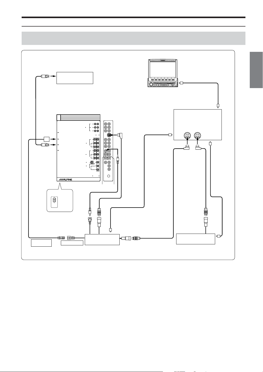
System Example
When connecting the Ai-NET compatible audio processor (Fiber digital compatible), Navigation
system, DVD player and changer
IVA-D901 Monitor
NVE-N852A/NVE-N871A
1
Navigation system
(Sold Separately)
IVA-D901
Tuner BOX
POWER SUPPLY
2
REMOTE IN/OUT
NAVIGATION IN
DISPLAY OUT
3
4
EQ/DIV
NORM
5
*Fiber digital Input terminal
(for head unit)
Audio Processor (Ai-NET)
(Fiber Digital compatible)
SUB W.
REAR
PRE IN/OUT
FRONT
L
R
Ai-NET
VIDEO
L
AUX OUT
AUDIO
R
1
2
VIDEO
(MONO)
L
AUX IN 1/2
AUDIO
R
1
2
3
VIDEO
CAMERA IN
(MONO)
L
AUX IN 3
AUDIO
R
RADIO ANTENNA IN
&
%
7
6
Ai-NET
cable
Fiber digital
Input terminal
(for DVD Player)
!
(Sold Separately)
66
9
8
Fiber optic cable
#
Ai-NET
cable
Fiber optic
cable
Fiber digital
Input terminal
(for Changer)
!
**
Fiber
optic cable
!
(Yellow)
(White/Brown)(White/Brown)
REMOTE OUT
(AUX 1)
$
REMOTE IN
DVD Video Player
(Sold Separately)
• When the fiber digital compatible product is connected, it is
necessary to set the mode of this unit. Refer to “Setting the Digital
Output” (page 31) and set to ON. Then refer to “Optical Digital
Input Selection for an External Audio Processor” (page 34) and
switch the setting.
•* When connecting with PXA-H510 :
- Connect the fiber digital input terminal to the DVD.
-IVA -D901, DVA-5200, DVA-5205 or DVA-5210 cannot be
connected simultaneously when fiber digital is in use.
• When the NVA-N751AS is connected to the Navigation System, use
the RGB conversion cable KWE-503N (Sold separately).
Ai-NET cable
"
**
Only connect fiber digital compatible CD Changer
CD Changer (Ai-NET)
(Sold Separately)
Continued
73-EN
Page 76

1 RGB Cable (Included with NVE-N852, not included
with NVE-N871A)
2 Remote IN/OUT Terminal
3 RGB Input Terminal
Connect this to the RGB output terminal of the Navigation
System.
4 System Switch
When connecting an equalizer or divider using Ai-NET
feature, place this switch in the EQ/DIV position. When no
device is connected, leave the switch in the NORM
position.
• Be sure to turn the power off to the unit before changing the
switch position.
5 Digital Output Terminal
6 Ai-NET Connector
Connect this to the output or input connector of other
product equipped with Ai-NET.
7 AUX Video Input (AUX1) Terminal
Connect the video output lead of a DVD video player or
DVD changer to this terminal.
8 RCA Extension Cable (Included with DVD video
player)
9 Ai-NET Cable (Included with DVD video player)
! Fiber optic Cable (Sold Separately)
" Ai-NET Cable (Included with Equalizer)
# Ai-NET Cable (Included with CD Changer)
$ Remote Control Output Lead (White/Brown)
Connect this lead to the remote control input lead. This
lead outputs the controlling signals from the remote
control.
% AUX Audio/Video Input (AUX2) Terminals
& AUX Audio Input (AUX1) Terminals
74-EN
Page 77
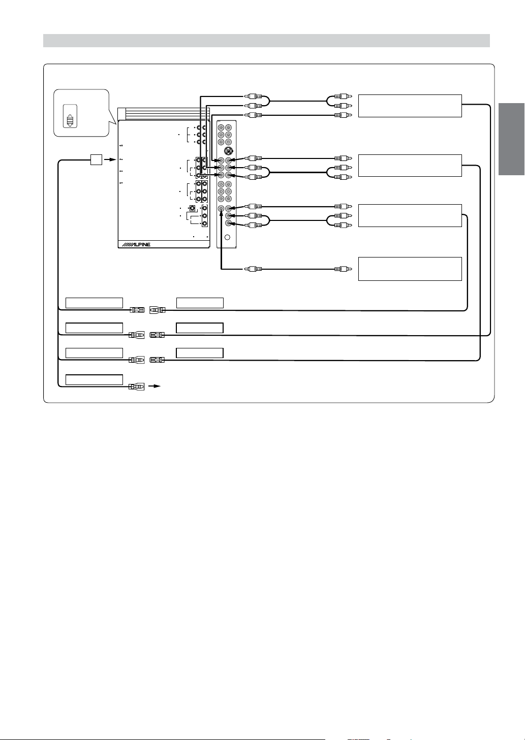
When Connecting External Equipment
2
IVA-D901
Tuner BOX
POWER SUPPLY
REMOTE IN/OUT
NAVIGATION IN
DISPLAY OUT
PRE IN/OUT
AUX OUT
AUX IN 1/2
CAMERA IN
AUX IN 3
SUB W.
FRONT
4
VIDEO
AUDIO
VIDEO
(MONO)
AUDIO
AUDIO
REAR
L
R
L
R
VIDEO
(MONO)
RADIO ANTENNA IN
L
R
Ai-NET
1
2
1
2
3
L
R
1
EQ/DIV
NORM
6
3
5
8
8
8
8
To Audio Input terminal
Rear monitor 1
(Sold Separately)
To Video Input terminal
To Video Input terminal
Rear monitor 2
(Sold Separately)
To Audio Input terminal
To Video Output terminal
TV Tuner or VCR
(Sold Separately)
To Audio Output terminal
To Video Output terminal
Back-up camera
(Sold Separately)
REMOTE OUT(AUX3)
7
REMOTE IN
(White/Brown)
REMOTE IN(AUX1)
!
REMOTE OUT
(White/Brown)
REMOTE IN(AUX2)
!
REMOTE OUT
(White/Brown)
REVERSE
(Orange/White)
9
Use only when back-up camera is connected.
1 System Switch
When connecting an equalizer or divider using Ai-NET
feature, place this switch in the EQ/DIV position. When no
device is connected, leave the switch in the NORM
position.
• Be sure to turn the power off to the unit before changing the
switch position.
2 Remote IN/OUT Terminal
3 AUX Video/Audio Output (AUX2) Terminal
Use when connecting an optional monitor etc.
4 AUX Video/Audio Output (AUX1) Terminal
Use when connecting an optional monitor etc.
5 AUX Video/Audio Input (AUX3) Terminal
6 CAMERA Input Terminal
Use when connecting a back-up camera.
7 Remote Control Output Lead (White/Brown)
Connect this lead to the remote control input lead. This
lead outputs the controlling signals from the remote
control.
(White/Brown)
(White/Brown)
(White/Brown)
8 RCA Extension Cable (Sold separately)
9 Connect to the plus side of the car's reverse lamp
which lights when the transmission is shifted into
reverse (R).
Switches the video picture to the back-up camera.
This is linked to putting the car into reverse (R).
! Remote Control Input Lead (White/Brown)
75-EN
Page 78

LIMITED WARRANTY
ALPINE ELECTRONICS OF AMERICA, INC. AND ALPINE OF
CANADA INC. ("Alpine"), are dedicated to quality craftsmanship
and are pleased to offer this Warranty. We suggest that you read it
thoroughly. Should you have any questions, please contact your
Dealer or Alpine at one of the telephone numbers listed below.
[ PRODUCTS COV ERED:
This Warranty covers Car Audio/Visual Products and Related
Accessories ("the product"). Products purchased in the
Canada are covered only in the Canada. Products purchased
in the U.S.A. are covered only in the U.S.A.
[ LENGTH OF WARRANTY:
This Warranty is in effect for one year from the date of the first
consumer purchase.
[ LIFETIME TAPE HEAD WARRANTY:
All Alpine Car Audio analog tape heads excluding Video tape
heads are warranted for life against manufacturing defects
causing failure.
[ WHO IS COVERED:
This Warranty only covers the original purchaser of the
product, who must reside in the United States, Puerto Rico or
Canada.
[ WHAT IS COVERED:
This Warranty covers defects in materials or workmanship
(parts and labor) in the product.
[ WHAT IS NOT COVERED:
This Warranty does not cover the following:
1 Damage occurring during shipment of the product to
Alpine for repair (claims must be presented to the carrier).
2 Damage caused by accident, abuse, negligence, misuse,
improper connections, improper operation or failure to
follow instructions contained in the Owner's manual.
3 Damage caused by act of God, including without limitation,
earthquake, fire, flood, storms or other acts of nature.
4 Any cost or expense related to the removal or reinstallation
of the product.
5 Service performed by an unauthorized person, company or
association.
6 Any product which has the serial number defaced, altered
or removed.
7 Any product which has been adjusted, altered or modified
without Alpine's consent.
8 Any product not distributed by Alpine within the United
States, Puerto Rico or Canada.
9 Any product not purchased from an Authorized Alpine
Dealer.
! Any product that has been determined to contain an
excessive amount of dust or dirt and any product that
contains other contaminants including liquid or foreign
objects.
[ HOW TO OBTAIN WARRANTY SERVICE:
1 You are responsible for delivery of the product to an
Authorized Alpine Service Center or Alpine for repair and
for payment of any initial shipping charges. Alpine will, at its
option, repair or replace the product with a new or
reconditioned product without charge. If the repairs are
covered by the warranty, and if the product was shipped to
an Authorized Alpine Service Center or Alpine, Alpine will
pay the return shipping charges.
2 You should provide a detailed description of the problem(s)
for which service is required.
3 You must supply proof of your purchase of the product.
4 You must package the product securely to avoid damage
during shipment.
[ HOW WE LIMIT IMPLIED WARRANTIES:
ANY IMPLIED WARRANTIES INCLUDING FITNESS FOR USE
AND MERCHANTABILITY ARE LIMITED IN DURATION TO THE
PERIOD OF THE EXPRESS WARRANTY SET FORTH ABOVE
AND NO PERSON IS AUTHORIZED TO ASSUME FOR ALPINE
ANY OTHER LIABILITY IN CONNECTION WITH THE SALE OF
THE PRODUCT.
[ HOW WE EXCLUDE CERTAIN DAMAGES:
ALPINE EXPRESSLY DISCLAIMS LIABILITY FOR INCIDENTAL
AND CONSEQUENTIAL DAMAGES CAUSED BY THE
PRODUCT. THE TERM "INCIDENTAL DAMAGES" REFERS TO
EXPENSES OF TRANSPORTING THE PRODUCT TO THE
ALPINE SERVICE CENTER, LOSS OF THE ORIGINAL
PURCHASER'S TIME, LOSS OF THE USE OF THE PRODUCT,
BUS FARES, CAR RENTALS OR OTHERS COSTS RELATING
TO THE CARE AND CUSTODY OF THE PRODUCT. THE TERM
"CONSEQUENTIAL DAMAGES" REFERS TO THE COST OF
REPAIRING OR REPLACING OTHER PROPERTY WHICH IS
DAMAGED WHEN THIS PRODUCT DOES NOT WORK
PROPERLY. THE REMEDIES PROVIDED UNDER THIS
WARRANTY ARE EXCLUSIVE AND IN LIEU OF ALL OTHERS.
[ HOW STATE/PROVINCIAL LAW RELATES TO THE
WARRANTY:
This Warranty gives you specific legal rights, and you may also
have other rights which vary form state to state and province to
province. In addition, some states/provinces do not allow
limitations on how long an implied warranty lasts, and some do
not allow the exclusion or limitation of incidental or
consequential damages. Accordingly, limitations as to these
matters contained herein may not apply to you.
[ IN CANADA ONLY:
This Warranty is not valid unless your Alpine car audio product
has been installed in your vehicle by an Authorized Installation
Center, and this warranty stamped upon installation by the
installation center.
[ HOW TO CONTACT CUSTOMER SERVICE:
Should the product require service, please call the following
number for your nearest Authorized Alpine Service Center.
U.S.A. 1-800-ALPINE-1 (1-800-257-4631)
CANADA 1-800-ALPINE-1 (1-800-257-4631)
Alpine Electronics of America, Inc., 19145 Gramercy Place, Torrance, California 90501, U.S.A.
Alpine Electronics of Canada, Inc., Suite 203, 7300 Warden Ave. Markham, Ontario, L3R 9Z6, Canada
 Loading...