

Page 1

FOR CAR USE ONLY/NUR FÜR AUTOMOBIL GEBRAUCH/POUR APPLICATION AUTOMOBILE UNIQUEMENT/PARA USO
EN AUTOMÓVILES/SOLO PER L’UTILIZZO IN AUTOMOBILE/ENDAST FÖR BILBRUK/ALLEEN VOOR GEBRUIK IN DE
AUTO/ТОЛЬКО ДЛЯ ИСПОЛЬЗОВАНИЯ В АВТОМОБИЛЯХ/DO UŻYCIA TYLKO W SAMOCHODZIE
8-INCH ADVANCED NAVI STATION
X802D-U
EN
DE
7-INCH ADVANCED NAVI STATION
INE-W710D
7-INCH MONITOR RECEIVER
iLX-702D
• INSTALLATION MANUAL
• INSTALLATIONSANLEITUNG
•GUIDE D’INSTALLATION
•MANUAL DE INSTALACIÓN
• MANUALE DI INSTALLAZIONE
• INSTALLATIONSHANDBOK
• INSTALLATIEHANDLEIDING
• РУКОВОДСТВО ПО УСТАНОВКЕ
• INSTRUKCJA MONTAŻU
FR
ES
IT
SE
NL
RU
ALPINE ELECTRONICS MARKETING, INC.
1-7, Yukigaya- Otsukamachi, O ta-ku,
Tokyo 145-0067, JAPAN
Phone: 03-5499-4531
ALPINE ELECTRONICS OF AMERICA, INC.
19145 Gramercy Place, Torrance,
California 90501, U.S.A.
Phone 1-800-ALPINE-1 (1-800-257-4631)
ALPINE ELECTRONICS OF AUSTRALIA PTY. LTD.
161-165 Princes Highway, Hallam
Victoria 3803, Australia
Phone 03-8787-1200
Yamagata Printing Co., Ltd.
2-6-34, Takashima, Nishi-ku, Yokohama,
Kanagawa, Japan
ALPINE ELECTRONICS GmbH
Wilhelm-Wagenfeld-Str. 1-3, 808 07 München, Germany
Fletchamste ad Highway, Coventry CV4 9T W, U.K.
Phone 089-32 42 640
ALPINE ELECTRONICS OF U.K. LTD.
Alpine Hous e
www.alpine.co.uk
ALPINE ELECTRONICS France S.A.R.L.
184 allée des Erables
CS 52016 – Villepinte
95 945 Roissy CDG cedex
FRANCE
Phone : + 33(0)1 48 63 89 89
ALPINE ITALIA S.p.A.
Viale Cris toforo Colombo 8,
20090 Trezzano sul Naviglio MI, Italy
Phone +39 02 48 4781
ALPINE ELECTRONICS DE ESPAÑA, S.A.
Portal de Gamarra 36, Pabellón, 32
01013 Vitoria (Alava)-APDO 133, Spain
Phone 945-283588
Designed by ALPINE Japan
Printed in Japan
68-34732Z08-A (Y-B5)
PL
Page 2

Page 3

Contents
WARNING ...................................................... 2
CAUTION ....................................................... 2
Precautions ................................................... 3
Accessory List ........................................................3
Installation .............................................................. 3
Caution concerning the installation
location ............................................................ 3
Mounting the GPS Antenna inside the
vehicle .............................................................. 3
Mounting the Microphone ............................... 4
Installation example using the Original
Mounting Bracket .......................................... 4
Connections ........................................................... 5
If an ACC power supply is not available ........8
System Example ..................................................... 9
ENGLISH
1-EN
Page 4

WARNING
This symbol means important instructions. Failure
to heed them can result in serious injury or death.
DO NOT DISASSEMBLE OR ALTER.
Doing so may result in an accident, fire or electric shock.
KEEP SMALL OBJEC TS SUCH AS SCREWS OUT OF THE REACH OF
CHILDREN.
Swallowing them may result in serious injury. If swallowed, consult
a physician immediately.
USE THE CORRECT AMPERE RATING WHEN REPLACING FUSES.
Failure to do so may result in fire or electric shock.
DO NOT USE BOLTS OR NUTS IN THE BRAKE OR STEERING SYSTEMS TO
MAKE GROUND CONNECTIONS.
Bolts or nuts used for the brake or steering systems (or any other
safety-related system), or tanks should NEVER be used for
installations or ground connections. Using such parts could disable
control of the vehicle and cause fire etc.
DO NOT INSTALL IN LOCATIONS WHICH MIGHT HINDER VEHICLE
OPERATION, SUCH AS THE STEERING WHEEL OR SHIFT LEVER.
Doing so may obstruct forward vision or hamper movement etc.
and results in serious accident.
DO NOT INSTALL THE MONITOR NEAR THE PASSENGER SEAT AIR BAG.
If the unit is not installed correctly the air bag may not function
correctly and when triggered the air bag may cause the monitor to
spring upwards causing an accident and injuries.
DO NOT BLOCK VENTS OR RADIATOR PANELS.
Doing so may cause heat to build up inside and may result in fire.
USE THIS PRODUCT FOR MOBILE 12V APPLICATIONS.
Use for other than its designed application may result in fire,
electric shock or other injury.
MAKE THE CORREC T CONNECTIONS.
Failure to make the proper connections may result in fire or
product damage.
USE ONLY IN CARS WITH A 12 VOLT NEGATIVE GROUND.
(Check with your dealer if you are not sure.) Failure to do so may
result in fire, etc.
BEFORE WIRING, DISCONNECT THE CABLE FROM THE NEGATIVE BATTERY
TERMINAL.
Failure to do so may result in electric shock or injury due to
electrical shorts.
DO NOT ALLOW CABLES TO BECOME ENTANGLED IN SURROUNDING
OBJECTS.
Arrange wiring and cables in compliance with the manual to
prevent obstructions when driving. Cables or wiring that obstruct
or hang up on places such as the steering wheel, shift lever, brake
pedals, etc. can be extremely hazardous.
DO NOT SPLICE INTO ELECTRICAL CABLES.
Never cut away cable insulation to supply power to other
equipment. Doing so will exceed the current carrying capacity of
the wire and result in fire or electric shock.
CAUTION
This symbol means important instructions. Failure
to heed them can result in injury or material
property damage.
HAVE THE WIRING AND INSTALLATION DONE BY EXPERTS.
The wiring and installation of this unit requires special technical
skill and experience. To ensure safety, always contact the dealer
where you purchased this product to have the work done.
USE SPECIFIED ACCESSORY PARTS AND INSTALL THEM SECURELY.
Be sure to use only the specified accessory parts. Use of other than
designated parts may damage this unit internally or may not
securely install the unit in place. This may cause parts to become
loose resulting in hazards or product failure.
ARRANGE THE WIRING SO IT IS NOT CRIMPED OR PINCHED BY A SHARP
METAL EDGE.
Route the cables and wiring away from moving parts (like the seat
rails) or sharp or pointed edges. This will prevent crimping and
damage to the wiring. If wiring passes through a hole in metal, use a
rubber grommet to prevent the wire’s insulation from being cut by
the metal edge of the hole.
DO NOT INSTALL IN LOCATIONS WITH HIGH MOISTURE OR DUST.
Avoid installing the unit in locations with high incidence of
mois ture or d ust. Moisture or dust that penetrates into th is unit may
result in product failure.
DO NOT DAMAGE PIPE OR WIRING WHEN DRILLING HOLES.
When drilling holes in the chassis for installation, take precautions
so as not to contact, damage or obstruct pipes, fuel lines, tanks or
electrical wiring. Failure to take such precautions may result in fire.
2-EN
Page 5

Precautions
Caution concerning the installation location
• Be sure to disconnect the cable from the (–) battery post before
installing your unit. This will reduce any chance of damage to the
unit in case of a short-circuit.
• Be sure to connect the colour coded leads according to the
diagram. Incorrect connections may cause the unit to
malfunction or damage to the vehicle’s electrical system.
• When making connections to the vehicle’s electrical system, be
aware of the factory installed components (e.g. on-board
computer). Do not tap into these leads to provide power for this
unit. When connecting the unit to the fuse box, make sure the
fuse for the intended circuit of the unit has the appropriate
amperage. When in doubt, consult your Alpine dealer.
• The unit uses female RCA-type jacks for connection to other
units (e.g. amplifier) having RCA connectors. You may need an
adaptor to connect other units. If so, please contact your
authorized Alpine dealer for assistance.
• Be sure to connect the speaker (–) leads to the speaker (–)
terminal. Never connect left and right channel speaker cables to
each other or to the vehicle body.
Accessory List
• X802D-U, INE-W710D or iLX-702D......................................................... 1
• Power cable....................................................................................................1
• GPS Antenna..................................................................................................1
• Antenna mounting plate...........................................................................1
• Cable clamp for antenna .....................................................................1set
• USB extension cable....................................................................................1
• PRE OUT cable ............................................................................................... 1
• Microphone....................................................................................................1
• CAN I/F cable .................................................................................................1
• W.REMOTE cable........................................................................................... 1
• Face plate (INE-W710D/iLX-702D only)................................................1
• HDMI Fixation Bracket................................................................................ 1
• Flush head screw (M5×8) ..........................................................................4
• Screw (M5×8).................................................................................................4
• Owner’s Manual......................................................................................1set
Installation
X802D-U user
To install the X802D-U, refer to the manual in the
separately purchased installation kit for each car type.
Caution
Do not block the unit’s fan, thus preventing air circulation. If
blocked, heat will accumulate inside the unit and may cause
a fire.
<example>
Air ventilation hole
Angle of installation
Install at an angle between horizontal and 30°. Note that installing at
an angle outside of this range will result in a loss of performance and
possibly damage.
0 - 30°
Mounting the GPS Antenna inside the vehicle
1 Clean the mounting location.
2 Put on the GPS Antenna mounting plate.
3 Mount the GPS Antenna.
GPS Antenna
Antenna mounting plate
This unit
• Do not mount the GPS Antenna inside the centre console.
- Mount the GPS Antenna on a flat plane of the dash board or rear
tray.
- Make sure the GPS Antenna is not covered (obstructed) by any
metallic surface or object.
• If the GPS Antenna is mounted near the unit, the reception becomes
poor, and the location of your vehicle may not be displayed correctly.
- Mount the GPS Antenna far away enough from the unit.
- Bundle the GPS Antenna cable away from the rear of the unit.
• Some thermal reflection type or thermal absorption type glass may
interrupt high frequency waves. If reception is poor with the antenna
installed inside the car, try to mount the antenna outside the car.
Rear of the Unit
3-EN
Page 6

Mounting the Microphone
For safe use, make sure of the following:
• Location is stable and firm.
• Driver’s view and operations are not obstructed.
• Microphone is located where the driver’s voice can be easily
picked up (for example, on the sun visor).
When you speak into the microphone, you should not have to change
your driving posture. This may cause a distraction, taking your
attention away from safely driving your vehicle. Carefully consider
direction and distance while mounting the microphone. Confirm that
the driver’s voice can be easily picked up at the selected location.
Microphone
Cable clamp
(Sold separately)
Installation example using the Original
Mounting Bracket
Note on using HDMI Connection Cables
When using HDMI connection cables, secure the cables to the HDMI
Terminals with the supplied HDMI Fixation Bracket.
1 Slide the HDMI Fixation Bracket into the grooves (A).
2 Secure it with the screw (B).
HDMI Terminal
(A)
(B)
(A)
HDMI Fixation Bracket
(Included)
1 Mount the original mounting bracket to the unit using
the supplied screws.
Ground Lead*
Chassis
Original Mounting Bracket
Screws (M5 × 8) (Included)
Face plate (Included)
* To securely connect the ground lead, use an already installed screw on a
metal part of the vehicle (marked ( )) or a clean, bare metal spot on the
vehicle’s chassis.
2 Connect all other leads of the unit according to details
described in the “Connections” (page 5).
3 Mounting the unit in a car.
• Fix the cables carefully. Do not damage them by tucking them into
movable parts, such as a seat rail, or by locating them against sharp or
pointed edges.
4-EN
Page 7
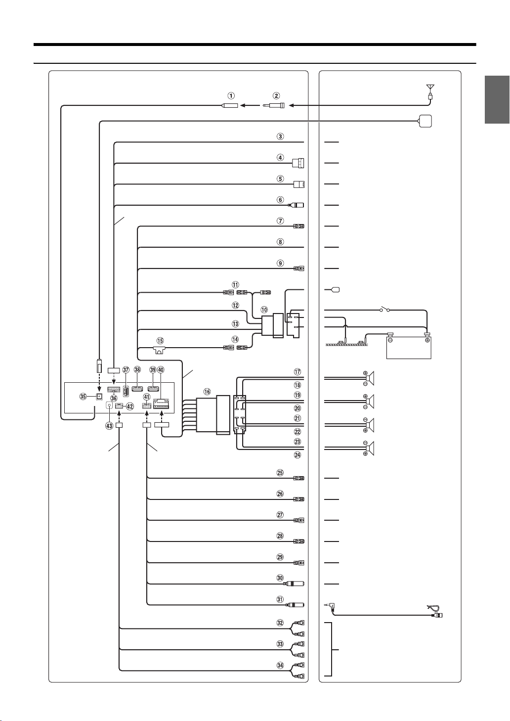
Connections
Antenna
ISO Antenna Plug
GPS Antenna (Included)
PRE OUT cable
CAN I/F cable
SPEED SENSOR
(Green/White )
CAMERA
CONNE CT2 I/ F
AUX IN PUT
REMO
(Blue/White)
REVERSE
(Orange/White)
PAR KING BRA KE
(Yellow/Blue)
ACC
(Red)
GND
(Black)
P. AN T
(Blue)
BATT
(Yellow)
W.R EMOT E c abl e
Power cable
(Green)
(Green/Black)
(White)
(White/Black)
(Grey/Black )
(Grey)
(Violet/Black)
(Violet)
To the vehicle speed pulse line
To Front or Rear camera
To C AN Int er fa ce b ox
To AUX output device
To amplifier or equalizer
To plus side of the back lamp signal
lead of the car
To the parking brake signal lead
To power antenna
Ignition key
Battery
Rear Left
Front Left
Speakers
Front Right
Rear Right
DVD REMOTE
(Brown)
MON REMOTE
(Brown)
REMOTE IN
(Brown/White)
REMOTE OUT
(Brown)
DVD STATUS IN
(Red/White)
STEERING REMOTE
MIC IN
SUBW
FRONT OUT
REAR OUT
To remote control input lead of
DVE-5300
To remote control input lead of Rear
Monitor
To remote control output lead
To remote control input lead
To remote control output lead of
DVE-5300
To steering remote control interface
box
Microphone (Included)
To input terminal of amplifier when
adding an external a mplifier
5-EN
Page 8

Radio Antenna Receptacle
ISO/JASO Antenna Adapter (sold separately)
ISO/JASO Antenna Adapter may be required, depending on the
vehicle.
Speed Sensor Lead (Green/White)
Improper connection of the speed pulse line may cause
important safety features of the vehicle to fail (such as the
brakes or air bags). Such failures may result in an accident and
loss of life. We strongly recommend that the installation be
performed by a trained, authorized Alpine dealer.
Direct CAMERA Input Connector
Use when the optional direct camera is connected.
CAN Interface Connector
To C AN I nterfa ce b ox
AUX Input Connector
Input lead for AUX video/audio signal.
• A separately sold AV/RCA interface cable (4-pole mini AV plug to
3-RCA) is required. For details on using an AV/RCA interface
cable (4-pole mini AV plug to 3-RCA), see “Usable AV/RCA
Interface Cable (4-pole mini AV plug to 3-RCA)” (page 7).
Remote Turn-On Lead (Blue/White)
Connect this lead to the remote turn- on lead of your amplifier or
signal processor.
Reverse Lead (Orange/White)
Connect to the plus side of the car’s reverse lights. These lights
illuminate when the transmission is shifted into reverse (R).
With this lead properly wired, the video picture automatically
switches to the rear camera whenever the car is put into reverse
(R).
Parking Brake Lead (Yellow/Blue)
Connect this lead to the power supply side of parking brake
switch to transmit the parking brake status signals to the unit.
ISO Power Supply Connector
Switched Power Lead (Ignition) (Red)
Connect this lead to an open terminal on the vehicle’s fuse box
or another unused power source that provides (+) 12V only
when the ignition is turned on or in the accessory position.
Ground Lead (Black)
Connect this lead to a good chassis ground on the vehicle.
Make sure the connection is made to bare metal and is securely
fastened using the sheet metal screw provided.
Power Antenna Lead (Blue)
Connect this lead to the +B terminal of your power antenna, if
applicable.
• This lead should be used only for controlling the vehicle’s power
antenna. Do not use this lead to turn on an amplifier or a signal
processor, etc.
Battery Lead (Yellow)
Connect this lead to the positive (+) post of the vehicle’s battery.
Fuse Holder (15A)
ISO Connector (Speaker Output)
Left Rear (+) Speaker Output Lead (Green)
Left Rear (–) Speaker Output Lead (Green/Black)
Left Front (+) Speaker Output Lead (White)
Left Front (–) Speaker Output Lead (White/Black)
Right Front (–) Speaker Output Lead (Grey/Black)
Right Front (+) Speaker Output Lead (Grey)
Right Rear (–) Speaker Output Lead (Violet/Black)
Right Rear (+) Speaker Output Lead (Violet)
Remote Control Output Lead (Brown) (For DVD Player
DVE-5300)
Connect this lead to the remote control input lead. This lead
outputs the controlling signals from the remote control.
Remote Control Output Lead (Brown) (For Rear Monitor)
Connect this lead to the remote control input lead. This lead
outputs the controlling signals from the remote control.
Remote Control Input Lead (Brown/White)
Connect the external Alpine product to the remote control
output lead.
6-EN
Page 9
Remote Control Output Lead (Brown)
Connect this lead to the remote control input lead. This lead
outputs the controlling signals from the remote control.
DVD Control Input Lead (Red/White) (For DVD Player
DVE-5300)
Connect the DVD Player DVE-5300 to the remote control output
lead.
Steering Remote Control Interface Connector
To steering remote control interface box.
For details about connecti ons, consult your nearest Alpine dealer.
MIC Input Connector
To microphone (Included)
• When using the included microphone, set Microphone Select to
“Add-on.” For details, refer to “Setting the Microphone Select” in
the OWNER’S MANUAL (CD-ROM).
Subwoofer RCA Connectors
RED is right and WHITE is left.
Front Output RCA Connectors
Can be used as Front Output RCA Connectors. RED is right and
WHITE is left.
Rear Output RCA Connectors
Can be used as Rear Output RCA Connectors. RED is right and
WHITE is left.
GPS Antenna Receptacle
Connect to GPS antenna (Included).
CAN I/F Connector
USB Connector
To USB flash drive, iPod/iPhone or Android smartphone.
HDMI Input Connector
HDMI Output Connector
Power Supply Connector
W.REMOTE Connector
PRE OUT Connector
DAB Antenna Connector
To DAB Antenna (sold separately).
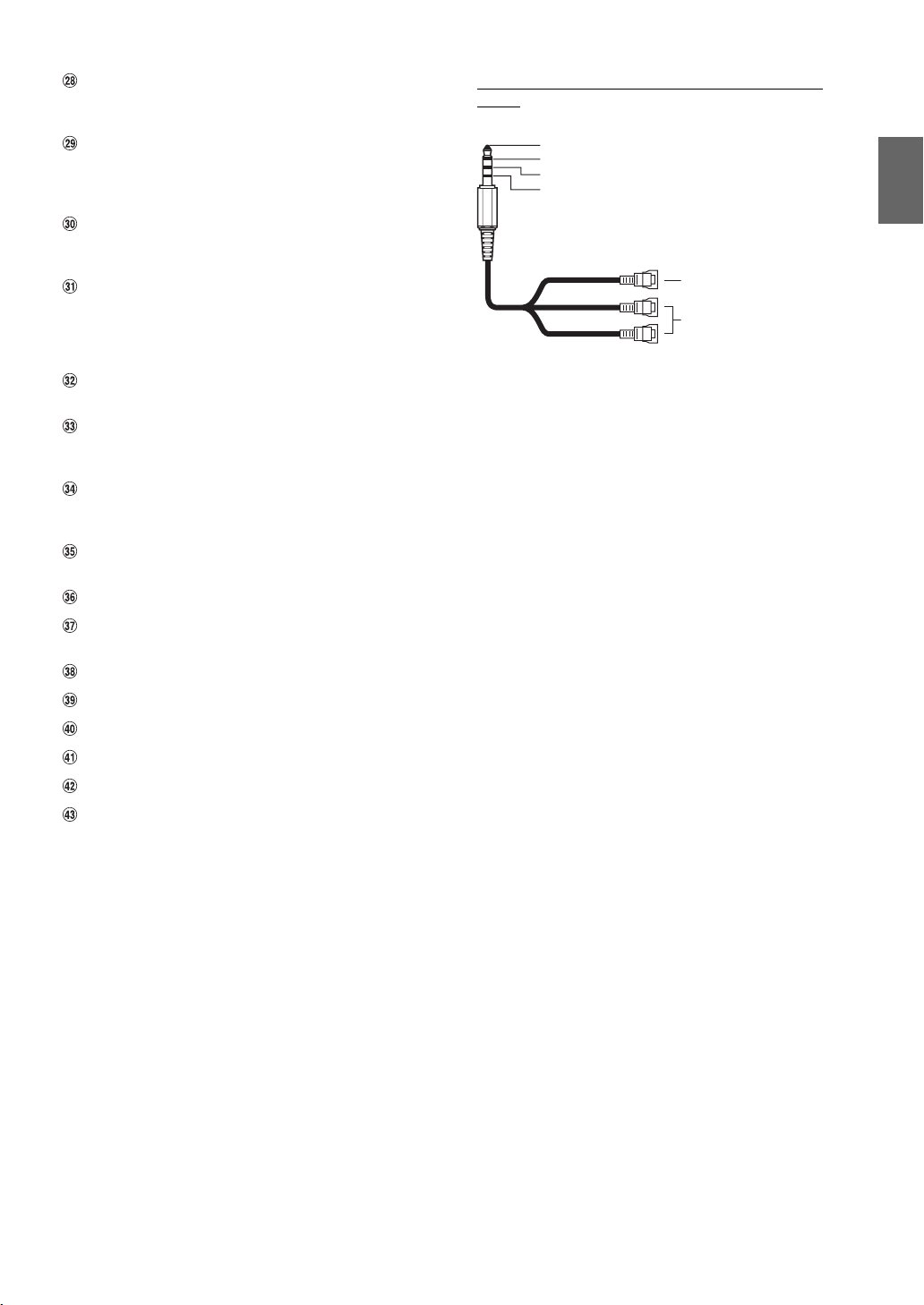
Usable AV/RCA Interface Cable (4-pole mini AV plug to
3-RCA)
Wiring convention of this system is as follows;
Audio L (White)
Audio R (Red)
Ground
Video (Yellow)
(Yellow)
(Red)
(White)
• Configuration commercially available 4-pole mini AV plugs is not
standardised.
Video input terminal
Audio input terminal (R, L)
7-EN
Page 10
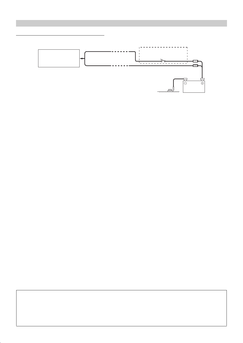
If an ACC power supply is not available
Connection Diagram of SPST Switch (sold separately)
ACC
X802D-U/
INE-W710D/
iLX-702D
• If your vehicle has no ACC power supply, add an SPST (single-pole, single-throw) switch (sold separately) and fuse (sold separately).
• The diagram and the fuse amperage shown above are in the case when the unit is used individually.
• If the switched power (ignition) lead of the unit is connected directly to the positive (+) post of the vehicle’s battery, the unit draws some current (several
hundred milliamperes) even when its switch is placed in the OFF position, and the battery may be discharged.
(Red)
BATTERY
(Yellow)
SPST SW (Optional)
FUSE (5A)
(Opti onal)
FUSE (20A)
(Optio nal)
Battery
To prevent external noise from entering the audio system.
• Locate the unit and route the leads at least 10 cm away from the car harness.
• Keep the battery power leads as far away from other leads as possible.
• Connect the ground lead securely to a bare metal spot (remove any paint, dirt or grease if necessary) of the car chassis.
• If you add an optional noise suppressor, connect it as far away from the unit as possible. Your Alpine dealer carries various noise
suppressors, contact them for further information.
• Your Alpine dealer knows best about noise prevention measures so consult your dealer for further information.
8-EN
Page 11
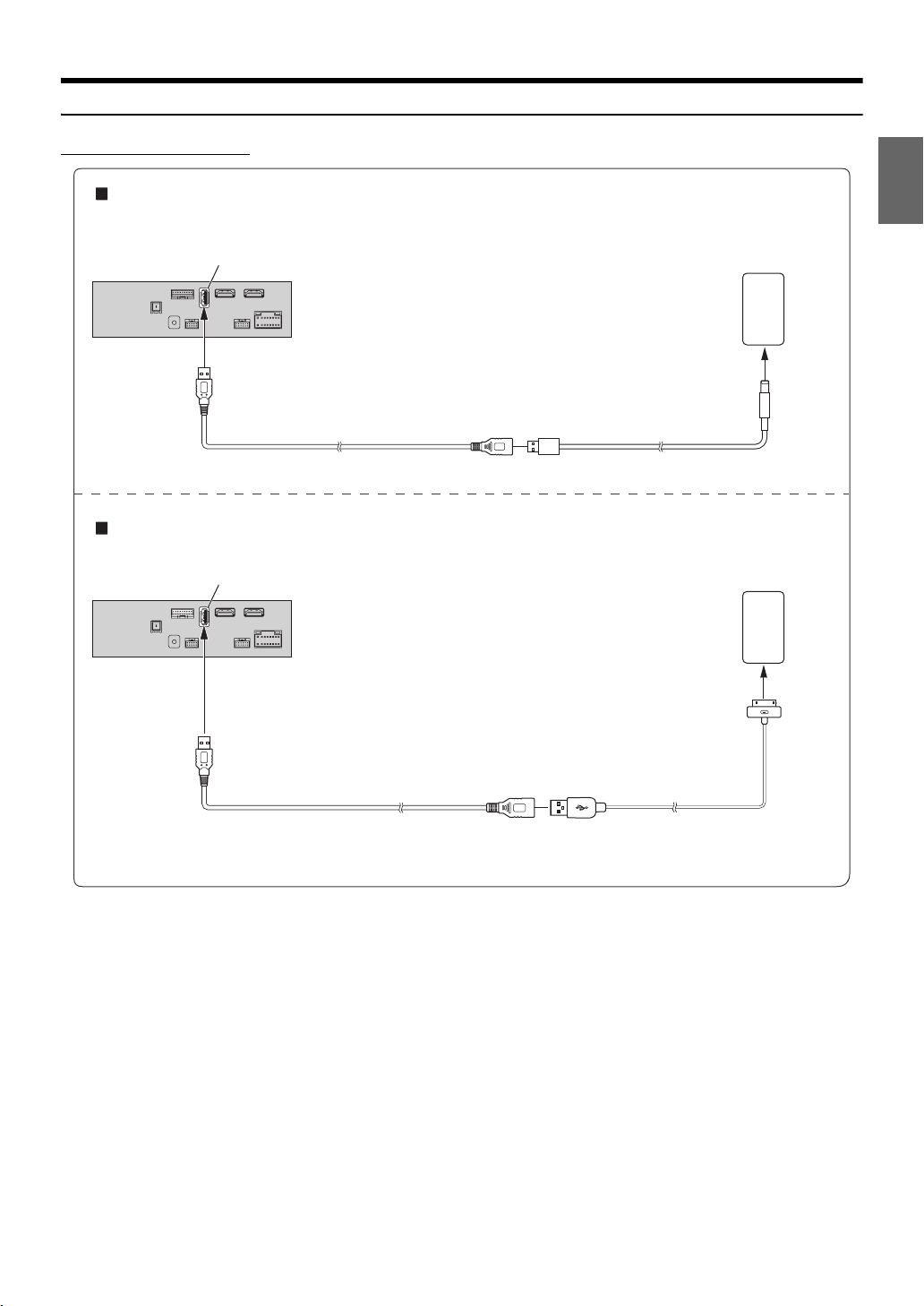
System Example
Connection of an iPod/iPhone
When connecting to an iPod/iPhone with a Lightning connector
USB connector
USB extension ca ble (Included)
When connecting to iPhone 4S
USB connector
iPod/iPhone with a Lightning
connecto r (sold separately )
Lightning to USB Cable
KCU-471i (sold separately)
iPhone 4S
(sold separately)
USB extension cable ( Included)
• Do not leave an iPod/iPhone in a vehicle for a long time. Heat and humidity may damage the iPod/iPhone, and you may not be able to play it again.
Included with iPhone 4S
9-EN
Page 12
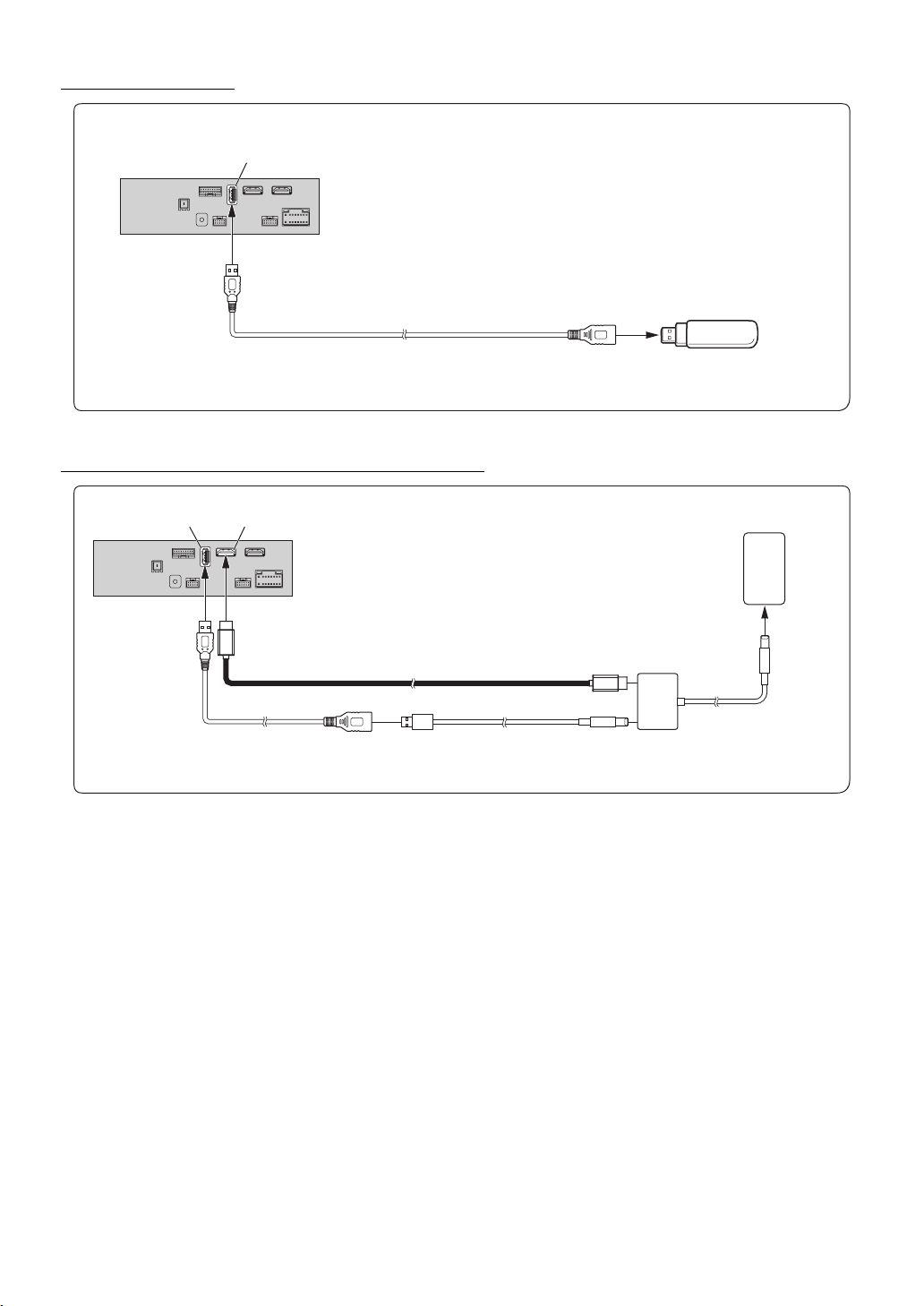
Connection of a Flash Drive
USB connector
USB extension ca ble (Included)
• Do not leave a flash drive in a vehicle for a long time. Heat and humidity may damage the flash drive.
Connection of an HDMI Device (iPhone with a Lightning connector)
USB Flash Dr ive (sold separately)
USB connector
HDMI input connecto r*
USB extension ca ble
(Included)
HDMI connection k it KCU-610HD (sold separately)
Lightning to USB Cable
KCU-471i (sold separately)
Lightning Digital AV Adapter
(Apple Inc., products)
(sold separately)
iPhone with a Lightning
connector (sold separately)
* When connecting an HDMI connection cable, be sure to secure it using the supplied HDMI Fixation Bracket. For details on how to secure it, see “Note on
using HDMI Connection Cables” (page 4).
• Set the HDMI Setup to “HDMI.” For details, refer to “HDMI Setup” in the OWNER’S MANUAL (CD-ROM).
10-EN
Page 13
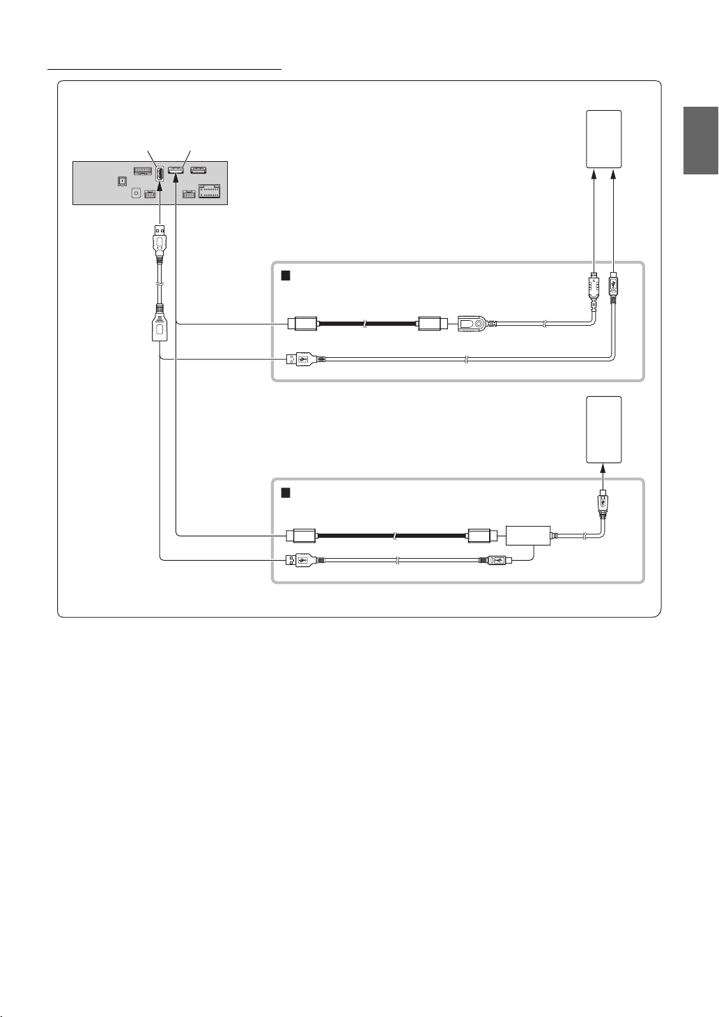
Connection of an HDMI Device (Android device)
USB connector
HDMI input connector*
Android device with
HDMI connector
(sold separately)
USB extension cable
(Included)
HDMI connection kit KCU-610HD (sold separately)
HDMI connection cabl e
Micro USB conversion cable
HDMI Type-D
conversion adapter
Android device with
MHL connector (sold
separately)
MHL connection kit KCU-610MH (sold separately)
HDMI connection cabl e
MHL conversion adapter
Micro USB conversion cable
• A connection kit or adapter kit suitable for the type of terminal on the connecting device is required.
• Set the HDMI Setup to “HDMI.” For details, refer to “HDMI Setup” in the OWNER’S MANUAL (CD-ROM).
* When connecting an HDMI connection cable, be sure to secure it using the supplied HDMI Fixation Bracket. For details on how to secure it, see “Note on
using HDMI Connection Cables” (page 4).
11-EN
Page 14
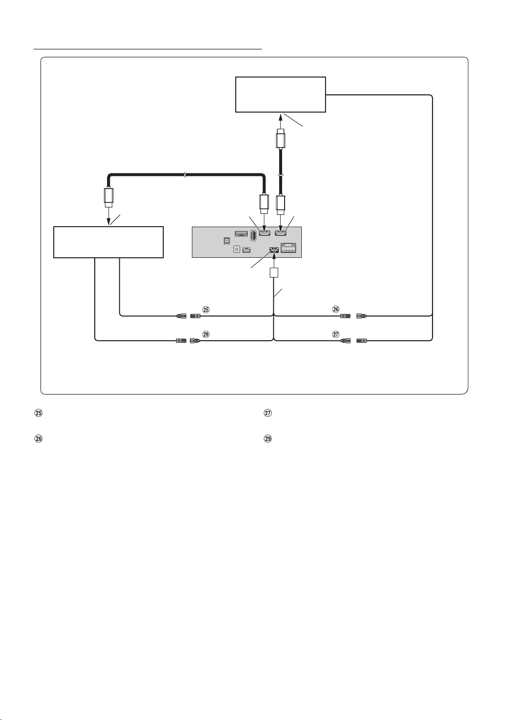
Connection of a DVE-5300 and a Rear Monitor with HDMI support
Rear Monitor with H DMI
support
(sold separately)
HDMI input connector
HDMI connection cab le (included with DVE-5300)
HDMI output connecto r HDMI input connecto r*
DVE-5300 (sold separately)
W.REMOTE connector
REMOTE IN
(Brown)
REMOTE OUT
(Brown)
DVD REMOTE
(Brown)
DVD STATUS IN
(Red/White )
Remote Control Output Lead (Brown) (For DVD Plyer
DVE-5300)
Remote Control Output Lead (Brown) (For Rear Monitor)
HDMI connection c able
(sold separately)
HDMI output connecto r*
W.R EMOT E ca ble
MON REMOTE
(Brown)
(Brown/White)
REMOTE IN
REMOTE OUTREMOTE IN
Remote Control Input Lead (Brown/White) (For Rear
Monitor)
DVD Control Input Lead (Red/White) (For DVD Player
DVE-5300)
* When connecting an HDMI connection cable, be sure to secure it using the supplied HDMI Fixation Bracket. For details on how to secure it, see “Note on
using HDMI Connection Cables” (page 4).
• Set the HDMI Setup to “DVD.” For details, refer to “HDMI Setup” in the OWNER’S MANUAL (CD-ROM).
12-EN
Page 15
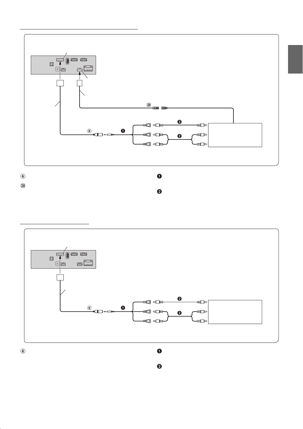
Connection of a Mobile Digital TV Receiver or USB Player
CAN I/F connecto r
W.REMOT connector
W.R EMOT E ca ble
CAN I/F cable
AUX IN PUT
REMOTE OUT
(Brown)
(Yellow)
(White)
(Red)
REMOTE IN
(White/Brown)
To Video Output terminal
Mobile Digital TV Receiver
(sold separately)
or
USB Player (sold separately)
To Audio Output terminal
AUX Input Connector
Remote Control Output Lead (Brown)
AV/RCA Interface Cable (4-pole mini AV plug to 3-RCA)
(sold separately)
RCA Extension Cable (sold separately)
• For details on using an AV/RCA interface cable (4-pole mini AV plug to 3-RCA), see “Usable AV/RCA Interface Cable (4-pole mini AV p lu g to 3- RC A) ”
(page 7).
• Set the AUX Name to “DVB-T” or “USB Player.” For details, refer to “Setting the Auxiliary (AUX) Name” in the OWNER’S MANUAL (CD-ROM).
Connection of an External Device
CAN I/F connecto r
CAN I/F cable
To Video Output terminal
External Device
(sold sepa rately)
To Audio Outpu t terminal
AUX IN PUT
(Yellow)
(Red)
(White)
AUX Input Connector AV/RCA Interface Cable (4-pole mini AV plug to 3-RCA)
(sold separately)
RCA Extension Cable (sold separately)
• You can change the name of an external device. For details, refer to “Setting the Auxiliary (AUX) Name” in the OWNER’S MANUAL (CD-ROM).
• For details on using an AV/RCA interface cable (4-pole mini AV plug to 3-RCA), see “Usable AV/RCA Interface Cable (4-pole mini AV p lu g to 3- RC A) ”
(page 7).
13-EN
Page 16
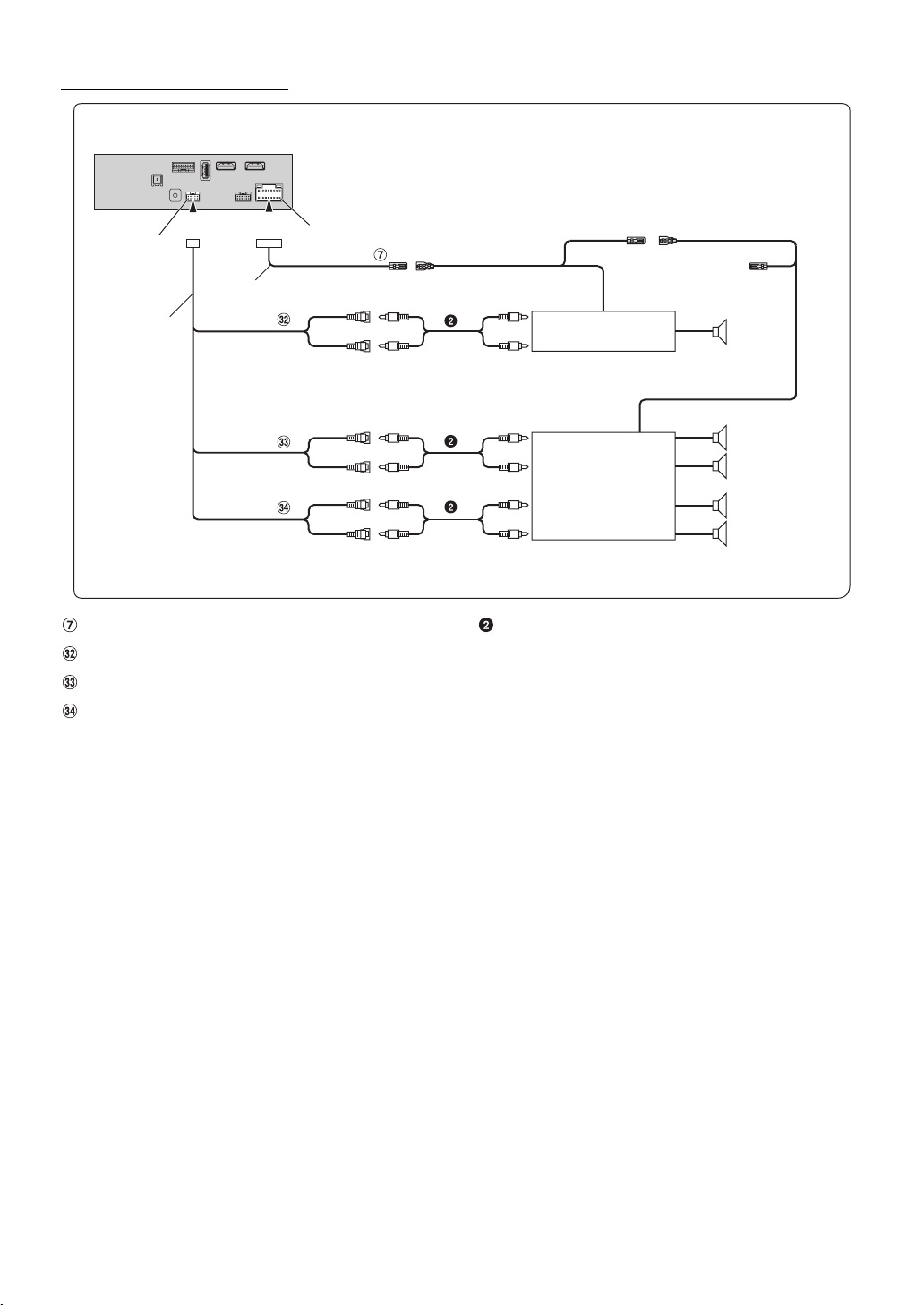
Connection of an External Amplifier
PRE OUT connect or
Power cable
PRE OUT cable
SUBW
FRONT OUT
REAR OUT
Remote Turn-On Lead (Blue/White)
Subwoofer RCA Connectors
Front Output RCA Connectors
Rear Output RCA Connectors
Power Supply connector
REMO
(Blue/White)
(Red)
(White)
(Red)
(White)
(Red)
(White)
REMOTE ON
(Blue/White)
Amplifier for subwoofer
(sold separately)
To subwoofer input terminal
To front input terminal
Amplifier 4 ch
(sold separately)
To rear input terminal
RCA Extension Cable (sold separately)
REMOTE ON
(Blue/White)
Subwoofer
Front speaker
Rear speaker
14-EN
Page 17
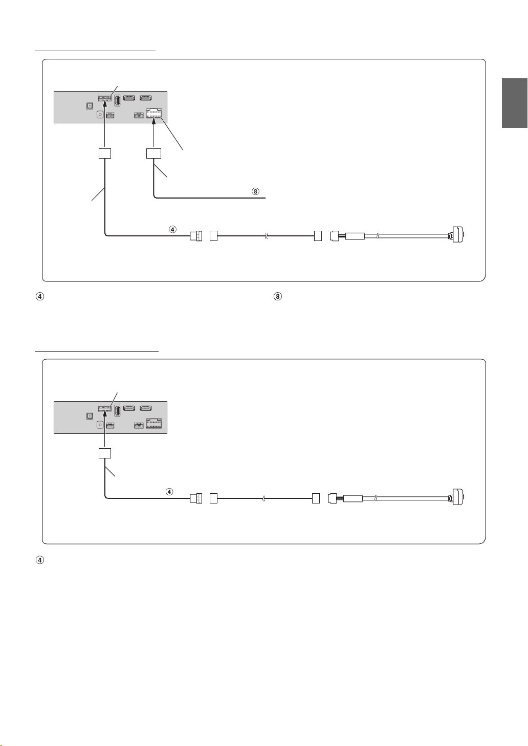
Connection of a Rearview camera
CAN I/F connecto r
Power Supply connector
Power cable
CAN I/F cable
CAMERA
Reverse
(Orange/White)
Camera extension cable
(included with direct rearview camera)
Connect to the plus s ide of the car’s reverse lamp.
HCE-C127D/HCE-C157D/HCE-C252RD
(sold separately)
Direct CAMERA Input Connector Reverse Lead (Orange/White)
• Set the Camera Select to “Rear.” For details, refer to “Setting the Camera Input” in the OWNER’S MANUAL (CD-ROM).
Connection of a Frontview camera
CAN I/F connecto r
CAN I/F cable
CAMERA
Camera extension cable
(included with direct rearview camera)
HCE-C257FD/HCE-C212FD
(sold separately)
Direct CAMERA Input Connector
• Set the Camera Select to “Front.” For details, refer to “Setting the Camera Input” in the OWNER’S MANUAL (CD-ROM).
15-EN
Page 18

 Loading...