

Page 1
Owner's Manual for
Vehicle
Contents
The Ultimate Driving
Machine
A-Z
Online Edition for Part no. 01 40 2 606 469 - 03 11 490
Page 2

Page 3

528i
535i
550i
535i xDrive
550i xDrive
Owner's Manual for Vehicle
Thank you for choosing a BMW.
The
more familiar you are with your vehicle, the better control you
will have on the road. We therefore strongly suggest:
Read this Owner's Manual before starting off in your new BMW.
Also use the Integrated Owner's Manual in your vehicle. It con‐
tains important information on vehicle operation that will help you
make full use of the technical features available in your BMW. The
manual also contains information designed to enhance operating
reliability and road safety, and to contribute to maintaining the
value of your BMW.
Any updates made after the editorial deadline for the printed or
integrated Owner's Manual are located in the appendix of the
printed quick reference for the vehicle.
Supplementary information can be found in the additional bro‐
chures in the onboard literature.
We wish you a safe and enjoyable drive.
BMW AG
Online Edition for Part no. 01 40 2 606 469 - 03 11 490
Page 4

© 2011 Bayerische Motoren Werke
Aktiengesellschaft
Munich, Germany
Reprinting, including excerpts, only with the written
consent of BMW AG, Munich.
US English II/11, 03 11 490
Printed on environmentally friendly paper, bleached
without chlorine, suitable for recycling.
Online Edition for Part no. 01 40 2 606 469 - 03 11 490
Page 5

Contents
The fastest way to find information on a partic‐
ular topic or item is by using the index, refer to
page 294.
Using this Owner's Manual
6 Notes
At a glance
12 Cockpit
16 iDrive
22 Voice activation system
24 Integrated Owner's Manual in the vehicle
Controls
28 Opening and closing
44 Adjusting
54 Transporting children safely
58 Driving
67 Displays
80 Lamps
85 Safety
95 Driving stability control systems
102 Driving comfort
126 Climate control
132 Interior equipment
138 Storage compartments
Communication
210 Telephone
221 Office
230 Contacts
232 BMW ConnectedDrive
Mobility
240 Refueling
241 Fuel
242 Wheels and tires
255 Engine compartment
257 Engine oil
260 Maintenance
262 Replacing components
269 Breakdown assistance
274 Care
Reference
280 Technical data
285 Short commands of the voice activation
system
294 Everything from A to Z
Driving tips
146 Things to remember when driving
Navigation
154 Navigation
Entertainment
172 Tone
174 Radio
181 CD/multimedia
201 Rear entertainment
Online Edition for Part no. 01 40 2 606 469 - 03 11 490
Reference Mobility Communication Entertainment Navigation Driving tips Controls At a glance
Page 6

Notes
Using this Owner's Manual
Notes
The fastest way to find information on a partic‐
ular topic is by using the index.
An initial overview of the vehicle is provided in
the first chapter.
Updates made after the editorial
deadline
Any
updates made after the editorial deadline for
the Owner's Manuals are located in the appen‐
dix of the printed quick reference for the vehicle.
Additional sources of information
Should you have any questions, your service
center will be glad to advise you at any time.
Information on BMW, e.g., on technology, is
available on the Internet: bmwusa.com.
Symbols
Indicates precautions that must be followed
precisely
sonal injury and serious damage to the vehicle.
◄ Marks the end of a specific item of informa‐
tion.
* Indicates special equipment, country-specific
equipment and optional accessories, as well as
equipment and functions not yet available at the
time of printing.
"..." Identifies Control Display texts used to se‐
lect individual functions.
›...‹ Verbal instructions to use with the voice ac‐
tivation system.
››...‹‹ Identifies the answers generated by the
voice activation system.
protect the environment.
in order to avoid the possibility of per‐
Refers to measures that can be taken to help
Symbols on vehicle components
Indicates that you should consult the rele‐
vant section of this Owner's Manual for infor‐
mation on a particular part or assembly.
Your individual vehicle
have decided in favor of a vehicle with indi‐
You
vidualized equipment and features.
This Owner's Manual describes the entire array
of options and equipment available for a specific
model.
As a result, the manual may contain accessories
and equipment that you may not have specified
for your own vehicle.
All options and special equipment are marked
with an asterisk *.
For options and equipment not described in this
Owner's Manual, please refer to the Supple‐
mentary Owner's Manuals.
On right-hand drive vehicles, some controls are
arranged differently than shown in the illustra‐
tions.
Status of the Owner's Manual
The manufacturer of your vehicle pursues a pol‐
icy of constant development that is conceived
to ensure that our vehicles continue to embody
the highest quality and safety standards. In rare
cases, therefore, the features described in this
Owner's Manual may differ from those in your
vehicle.
Updates made after the editorial
deadline
Any updates made after the editorial deadline for
the Owner's Manuals are located in the appen‐
dix of the printed quick reference for the vehicle.
6
Online Edition for Part no. 01 40 2 606 469 - 03 11 490
Page 7

For your own safety
Maintenance and repairs
Advanced technology, e.g., the use of modern
materials
quires suitable maintenance and repair meth‐
ods.
Therefore, have this work performed only by a
BMW center or a workshop that works accord‐
ing to BMW repair procedures with appropri‐
ately trained personnel.
If this work is not carried out properly, there is
the danger of subsequent damage and related
safety hazards.
Parts and Accessories
For your own safety, use genuine parts and ac‐
cessories approved by BMW. When you pur‐
chase accessories tested and approved by
BMW and Genuine BMW Parts, you simultane‐
ously acquire the assurance that they have been
thoroughly tested by BMW to ensure optimum
performance when installed on your vehicle.
BMW warrants these parts to be free from de‐
fects in material and workmanship. BMW will not
accept any liability for damage resulting from in‐
stallation of parts and accessories not approved
by BMW. BMW cannot test every product made
by other manufacturers to verify if it can be used
on a BMW safely and without risk to either the
vehicle, its operation, or its occupants. Genuine
BMW Parts, BMW Accessories and other prod‐
ucts approved by BMW, together with profes‐
sional advice on using these items, are available
from all BMW centers. Installation and operation
of non-BMW approved accessories such as
alarms, radios, amplifiers, radar detectors,
wheels, suspension components, brake dust
shields, telephones, including operation of any
mobile phone from within the vehicle without
using an externally mounted antenna, or trans‐
ceiver equipment, for instance, CBs, walkietalkies, ham radios or similar accessories, may
cause extensive damage to the vehicle, com‐
promise its safety, interfere with the vehicle's
electrical system or affect the validity of the
BMW Limited Warranty. See your BMW center
and high-performance electronics, re‐
for additional information. Maintenance, re‐
placement,
vices and systems may be performed by any au‐
tomotive repair establishment or individual
using any certified automotive part.
or repair of the emission control de‐
California Proposition 65 Warning
California laws require us to state the following
warning:
Engine exhaust and a wide variety of automobile
components and parts, including components
found in the interior furnishings in a vehicle, con‐
tain or emit chemicals known to the State of Cal‐
ifornia to cause cancer and birth defects and re‐
productive harm. In addition, certain fluids
contained in vehicles and certain products of
component wear contain or emit chemicals
known to the State of California to cause cancer
and birth defects or other reproductive harm.
Battery posts, terminals and related accessories
contain lead and lead compounds. Wash your
hands after handling. Used engine oil contains
chemicals that have caused cancer in laboratory
animals. Always protect your skin by washing
thoroughly with soap and water.
Service and warranty
We recommend that you read this publication
thoroughly. Your vehicle is covered by the fol‐
lowing warranties:
▷ New Vehicle Limited Warranty.
▷ Rust Perforation Limited Warranty.
▷ Federal Emissions System Defect Warranty.
▷ Federal Emissions Performance Warranty.
▷ California Emission Control System Limited
Warranty.
Detailed information about these warranties is
listed in the Service and Warranty Information
Booklet for US models or in the Warranty and
Service Guide Booklet for Canadian models.
Your vehicle has been specifically adapted and
designed to meet the particular operating con‐
ditions and homologation requirements in your
country and continental region in order to deliver
the full driving pleasure while the vehicle is op‐
erated under those conditions. If you wish to op‐
Online Edition for Part no. 01 40 2 606 469 - 03 11 490
7
Reference Mobility Communication Entertainment Navigation Driving tips Controls At a glance
Page 8

erate your vehicle in another country or region,
you may be required to adapt your vehicle to
meet different prevailing operating conditions
and homologation requirements. You should
also be aware of any applicable warranty limita‐
Notes
or exclusions for such country or region. In
tions
such case, please contact Customer Relations
for further information.
Reporting safety defects
For US customers
The following only applies to vehicles owned
and operated in the US.
If you believe that your vehicle has a defect
which could cause a crash or could cause injury
or death, you should immediately inform the Na‐
tional Highway Traffic Safety Administration
NHTSA, in addition to notifying BMW of North
America, LLC, P.O. Box 1227, Westwood, New
Jersey 07675-1227, Telephone
1-800-831-1117.
If NHTSA receives similar complaints, it may
open an investigation, and if it finds that a safety
defect exists in a group of vehicles, it may order
a recall and remedy campaign.
However, NHTSA cannot become involved in
individual problems between you, your dealer,
or BMW of North America, LLC.
To contact NHTSA, you may call the Vehicle
Safety Hotline toll-free at 1-888-327-4236
(TTY: 1-800-424-9153); go to http://www.safe‐
rcar.gov; or write to: Administrator, NHTSA, 400
Seventh Street, SW., Washington, DC 20590.
You can also obtain other information about mo‐
tor vehicle safety from http://www.safercar.gov
For Canadian customers
Canadian customers who wish to report a
safety-related defect to Transport Canada, De‐
fect Investigations and Recalls, may telephone
the toll-free hotline 1-800-333-0510. You can
also obtain other information about motor vehi‐
cle safety from http://www.tc.gc.ca/roadsafety.
8
Online Edition for Part no. 01 40 2 606 469 - 03 11 490
Page 9

Online Edition for Part no. 01 40 2 606 469 - 03 11 490
9
Reference Mobility Communication Entertainment Navigation Driving tips Controls At a glance
Page 10

Online Edition for Part no. 01 40 2 606 469 - 03 11 490
Page 11

At a glance
These overviews of buttons, switches and
displays are intended to familiarize you with your
vehicle. You will also become quickly acquainted
with the available control concepts and options.
Online Edition for Part no. 01 40 2 606 469 - 03 11 490
Page 12
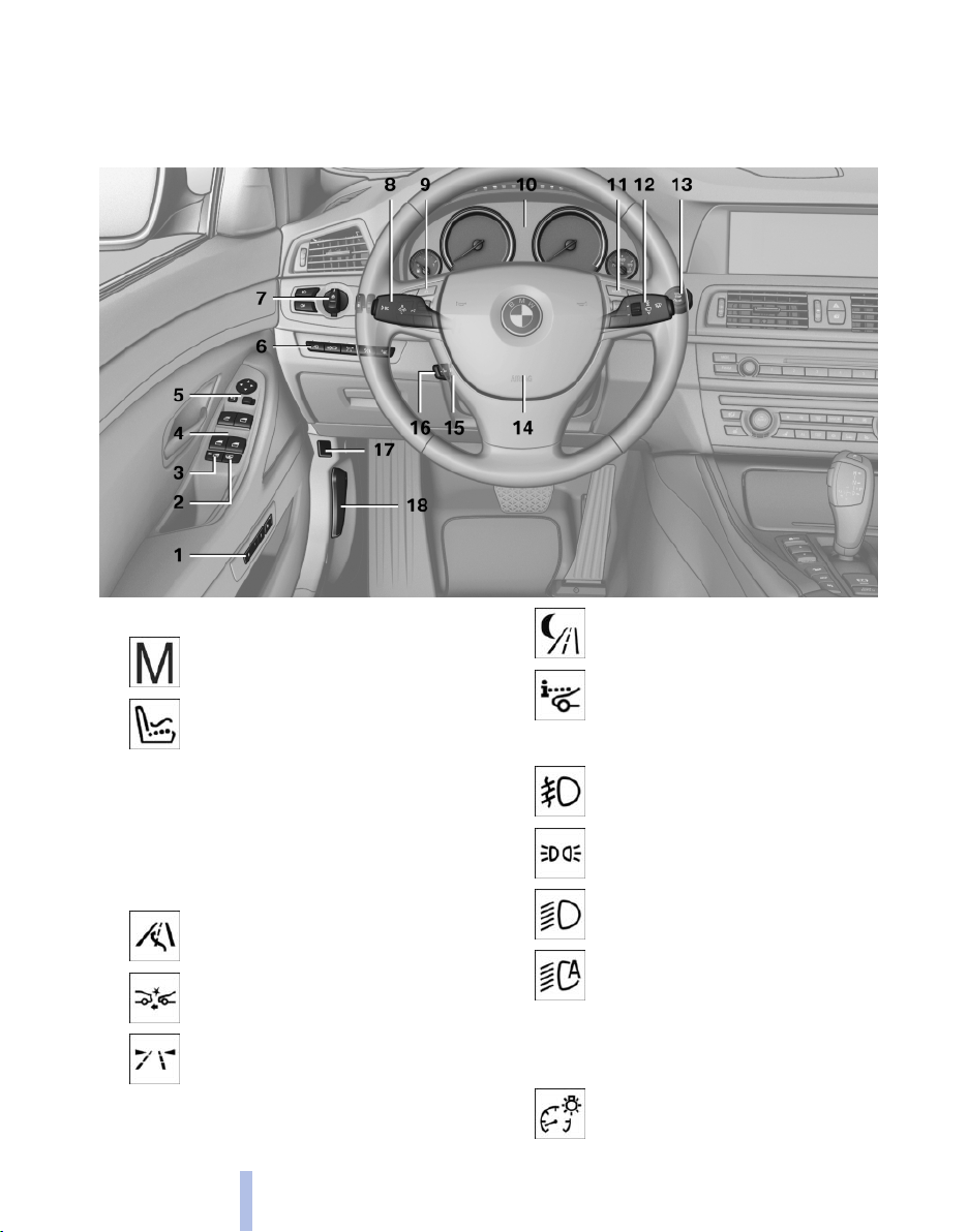
Cockpit
All around the steering wheel
Cockpit
1 Seating comfort functions*
Seat, mirror, steering wheel mem‐
ory* 51
Active seat* 46
2 Roller sunblinds* 41
3 Rear window safety switch 41
4 Power windows 40
5 Exterior mirror operation 51
6 Driver assistance systems*
Active Blind Spot Detec‐
tion* 92
Collision warning* 108
Lane departure warning* 91
12
Online Edition for Part no. 01 40 2 606 469 - 03 11 490
7 Lamps
Night Vision with pedestrian de‐
tection* 122
Head-up Display* 124
Front fog lamps 83
Parking lamps 80
Low beams 80
Automatic headlamp con‐
trol* 81
Daytime running lights* 81
Adaptive light control
High-beam Assistant* 82
Instrument lighting 83
* 81
Page 13
8 Steering column stalk, left
Turn signal 62
High beams, head‐
lamp flasher 62
High-beam Assistant* 82
Roadside parking lamps 81
Computer 75
9 Steering wheel buttons, left
Store speed* 110 103
Resume speed 111 104
Cruise control on/off, interrupt‐
ing 110 102
Increase distance* 104
Voice activation* 22
Telephone* 210
12 Steering column stalk, right
Windshield wipers 62
Rain sensor* 63
Clean the windshields and head‐
lamps* 62
13 Start/stop the engine and switch
the ignition on/off 59
14 Horn
15 Steering wheel heating* 53
16 Adjust the steering wheel 53
17 Open the trunk lid 35
Decrease distance* 104
10 Instrument cluster 67
11 Steering wheel buttons, right
Entertainment source
Volume
Online Edition for Part no. 01 40 2 606 469 - 03 11 490
18 Unlocking the hood
13
Reference Mobility Communication Entertainment Navigation Driving tips Controls At a glance
Page 14
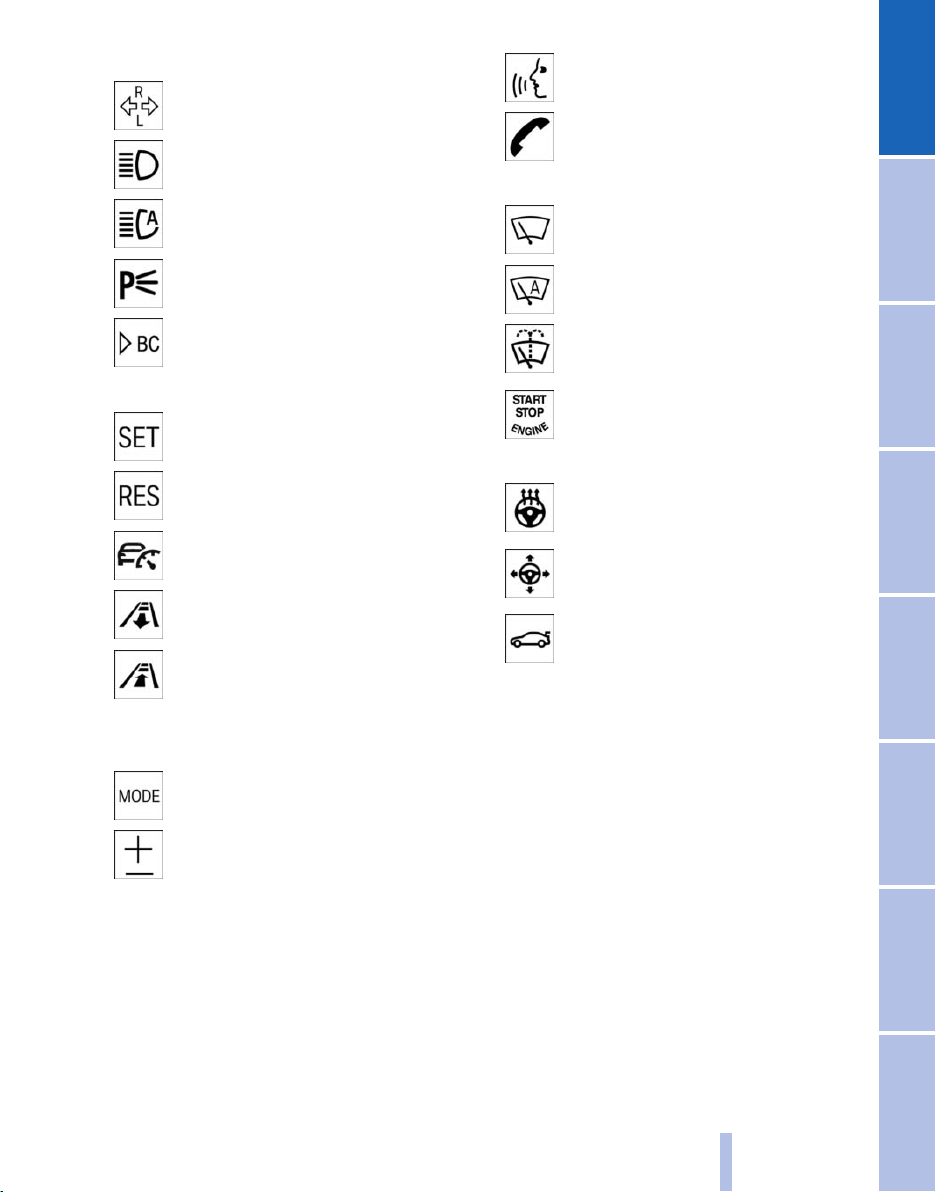
All around the center console
Cockpit
1 Headliner 15
2 Control Display 16
3 Glove compartment 138
4 Air vent 129
5 Hazard warning system 269
Central locking system 35
6 Radio 174
CD/Multimedia 181
7 Automatic climate control 126
8 Controller with buttons 16
9 Parking brake 60
Auto Hold* 60
10 PDC Park Distance Con‐
trol* 111
Top View* 116
Backup camera* 113
Parking assistant* 118
Side View* 117
11 Dynamic Driving Control* 99
DSC Dynamic Stability Con‐
trol 95
12 Transmission selector lever
14
Online Edition for Part no. 01 40 2 606 469 - 03 11 490
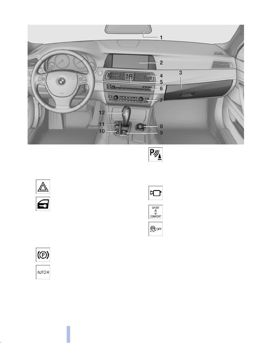
Page 15
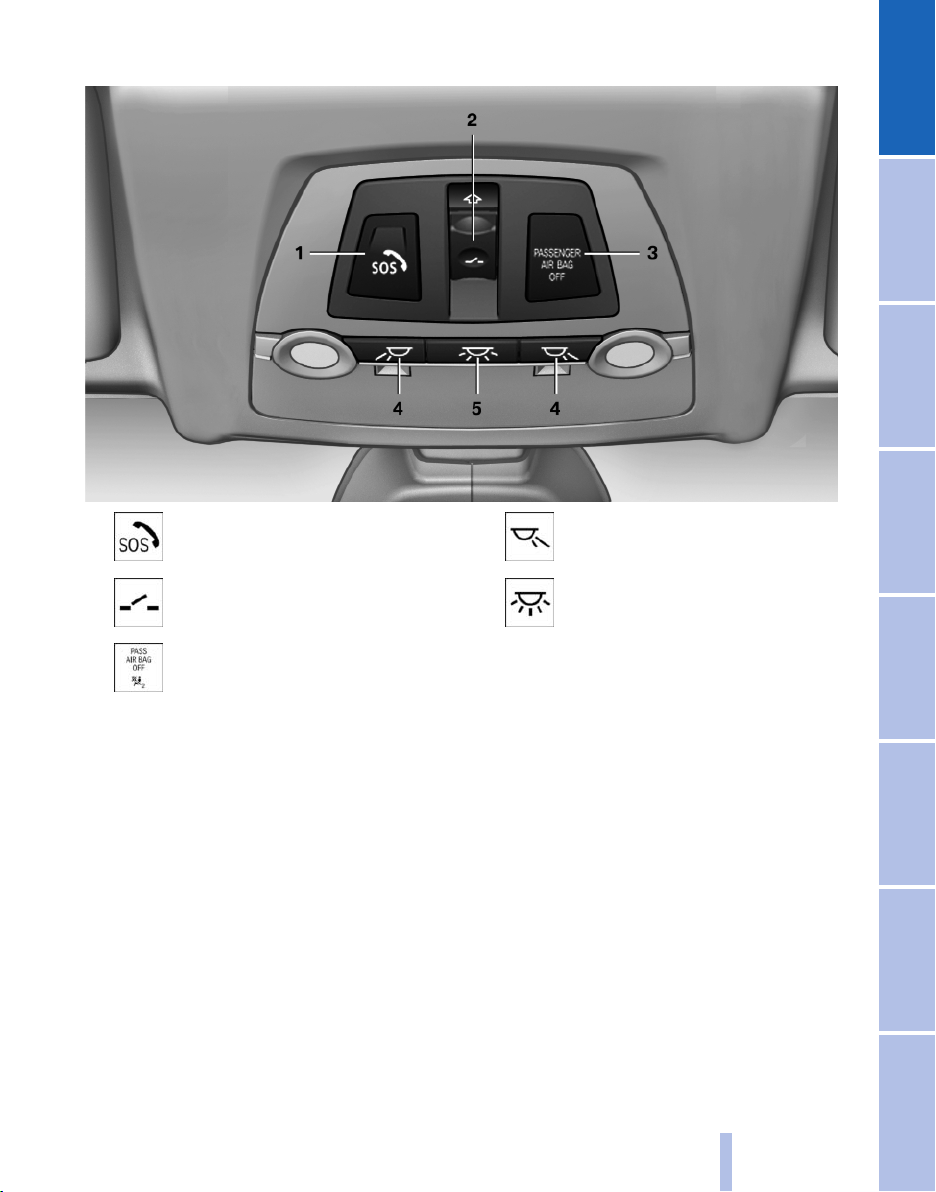
All around the headliner
1 Emergency Request* 269
2 Glass sunroof, powered* 41
3 Indicator lamp, front passenger
airbag* 87
4 Reading lamps* 84
5 Interior lamps 83
Online Edition for Part no. 01 40 2 606 469 - 03 11 490
15
Reference Mobility Communication Entertainment Navigation Driving tips Controls At a glance
Page 16
iDrive
The concept
iDrive
The
iDrive combines the functions of a multitude
of switches. Thus, these functions can be oper‐
ated from a central location.
Using the iDrive during a trip
To avoid becoming distracted and posing
an unnecessary hazard to your vehicle's occu‐
pants and to other road users, never attempt to
use the controls or enter information unless traf‐
fic and road conditions allow this.◀
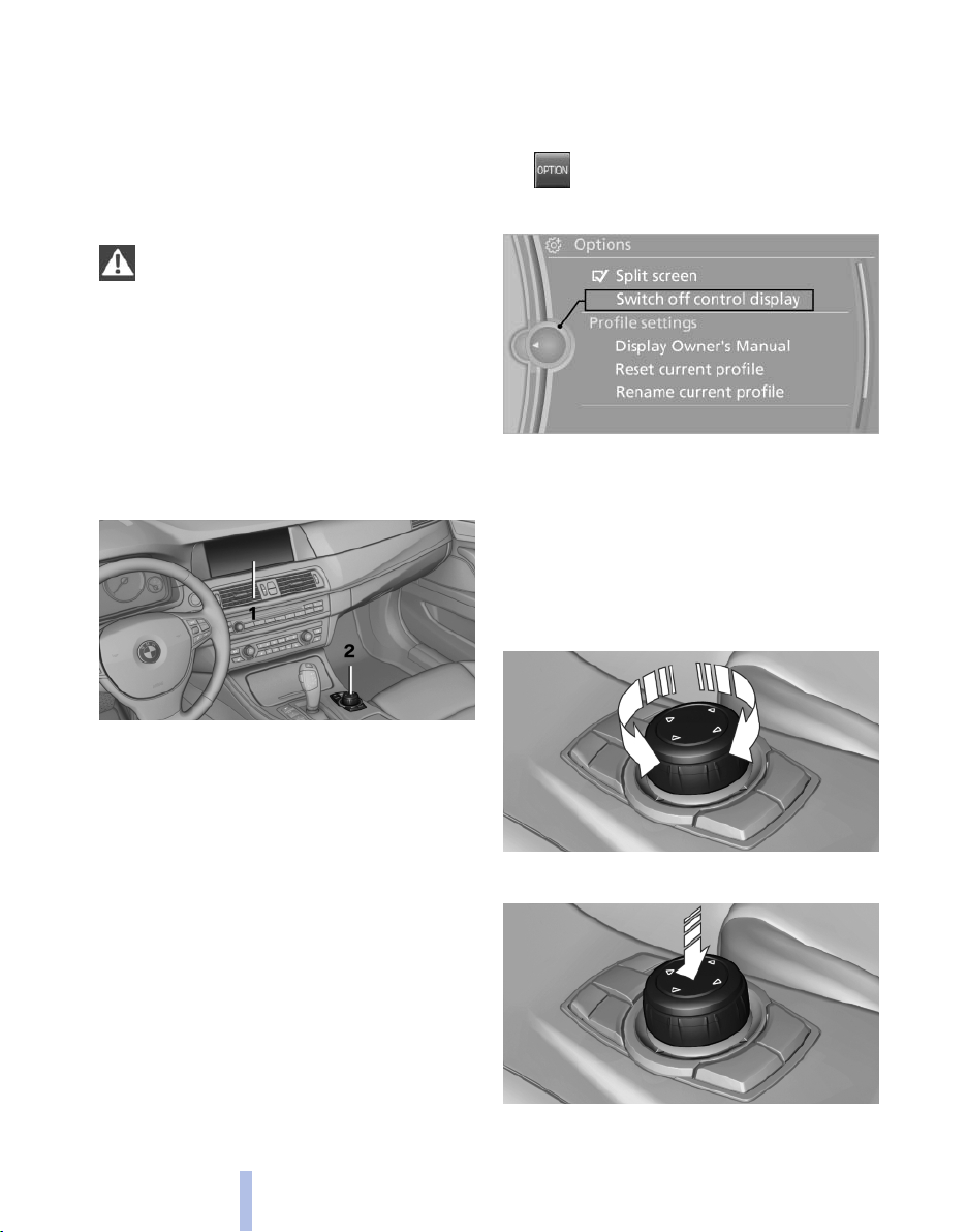
Controls at a glance
Controls
Switching off
1.
2. "Switch off control display"
Press the button.
Switching on
Press the controller again to switch the screen
back on.
Controller
Select menu items and create settings.
1. Turn.
1 Control Display
2 Controller with buttons
buttons can be used to open the menus
The
directly. The controller can be used to select
menu items and create the settings.
Control Display
Notes
▷ To clean the Control Display, follow the care
instructions.
▷ Do not place objects close to the Control
Display; otherwise, the Control Display can
be damaged.
16
Online Edition for Part no. 01 40 2 606 469 - 03 11 490
2. Press.
Page 17
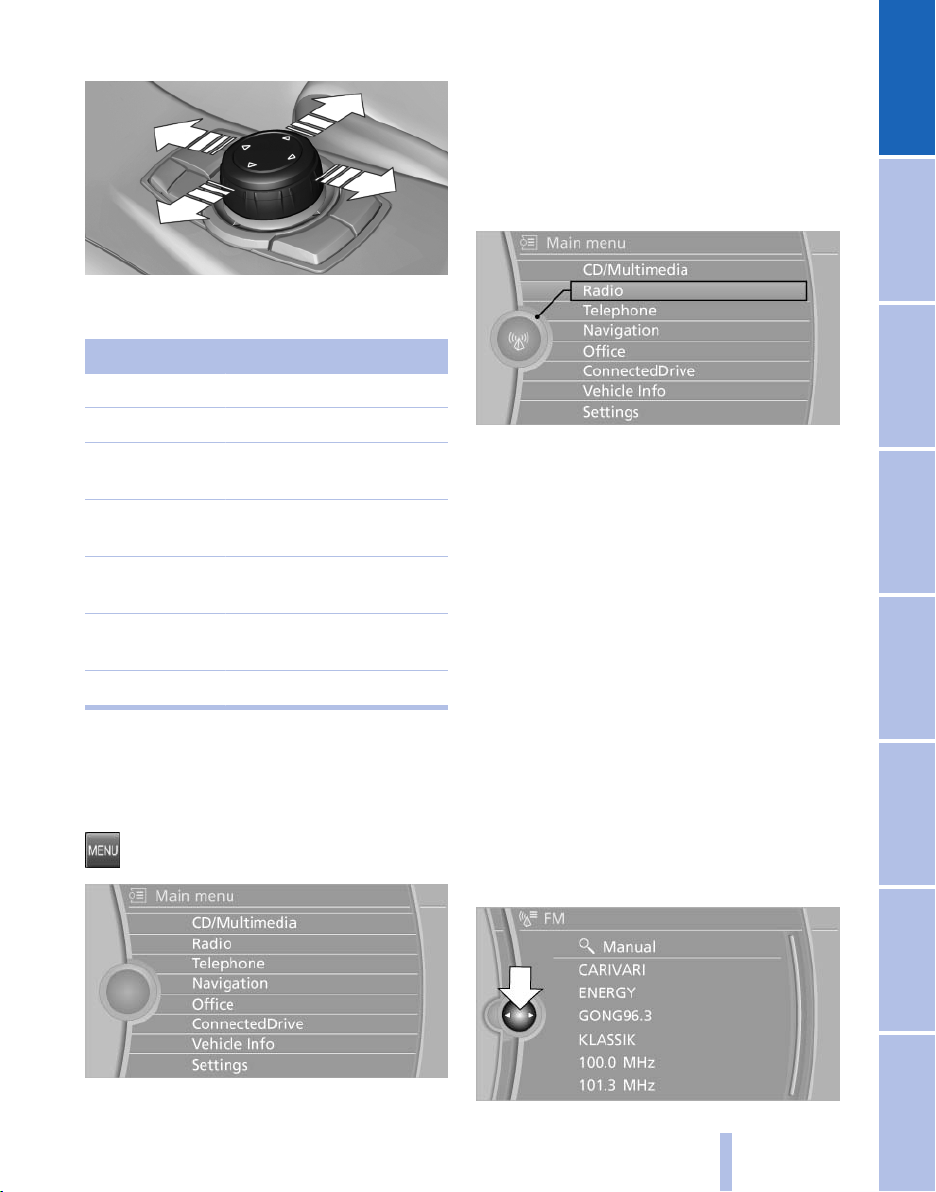
3. Move in four directions.
Buttons on controller
Press the button Function
MENU Open the main menu.
RADIO Opens the Radio menu.
CD Opens the CD/Multimedia
menu.
NAV Opens the Navigation map
view.
TEL Opens the Telephone
menu.
BACK Displays the previous
panel.
OPTION Opens the Options menu.
Operating concept
Opening the main menu
Press the button.
All iDrive functions can be called up via the main
menu.
Selecting menu items
Menu items shown in white can be selected.
1. Turn the controller until the desired menu
item is highlighted.
2. Press the controller.
Menu items in the Owner's Manual
In the Owner's Manual, menu items that can be
selected are set in quotation marks, e.g.,
"Settings".
Changing between panels
After a menu item is selected, e.g.,
new panel is displayed. Panels can overlap.
▷ Move the controller to the left.
The
current panel is closed and the previous
panel is displayed.
The previous panel is opened again by
pressing the BACK button. In this case, the
current panel is not closed.
▷ Move the controller to the right.
A new panel is opened on top of the previous
display.
"Radio", a
The main menu is displayed.
Online Edition for Part no. 01 40 2 606 469 - 03 11 490
17
Reference Mobility Communication Entertainment Navigation Driving tips Controls At a glance
Page 18
White arrows pointing to the left or right indicate
that additional panels can be opened.
View of an opened menu
iDrive
a menu is opened, it generally opens with
When
the panel that was last selected in that menu. To
display the first panel of a menu:
▷ Move the controller to the left repeatedly
until the first panel is displayed.
▷ Press the menu button on the controller
twice.
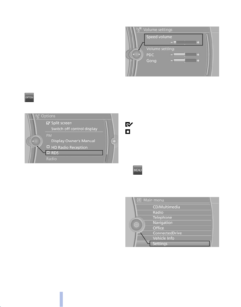
Opening the Options menu
Press the button.
The "Options" menu is displayed.
Additional options: move the controller to the
repeatedly until the "Options" menu is dis‐
right
played.
Options menu
The "Options" menu consists of various areas:
▷ Screen settings, e.g., "Split screen".
This area remains unchanged.
▷ Control options for the selected main menu,
e.g., for "Radio".
▷ If applicable, further operating options for
the selected menu, e.g., "Store station".
2. Turn the controller until the desired setting
is displayed.
3. Press the controller.
Activating/deactivating the functions
Several menu items are preceded by a check‐
box. It indicates whether the function is acti‐
vated or deactivated. Selecting the menu item
activates or deactivates the function.
The function is activated.
The function is deactivated.
Example: setting the clock
Setting the clock
1. Press the button. The main menu is
displayed.
2. Turn the controller until "Settings" is high‐
lighted, and then press the controller.
Changing settings
1. Select a field.
18
3. If necessary, move the controller to the left
to display "Time/Date"
Online Edition for Part no. 01 40 2 606 469 - 03 11 490
.
Page 19
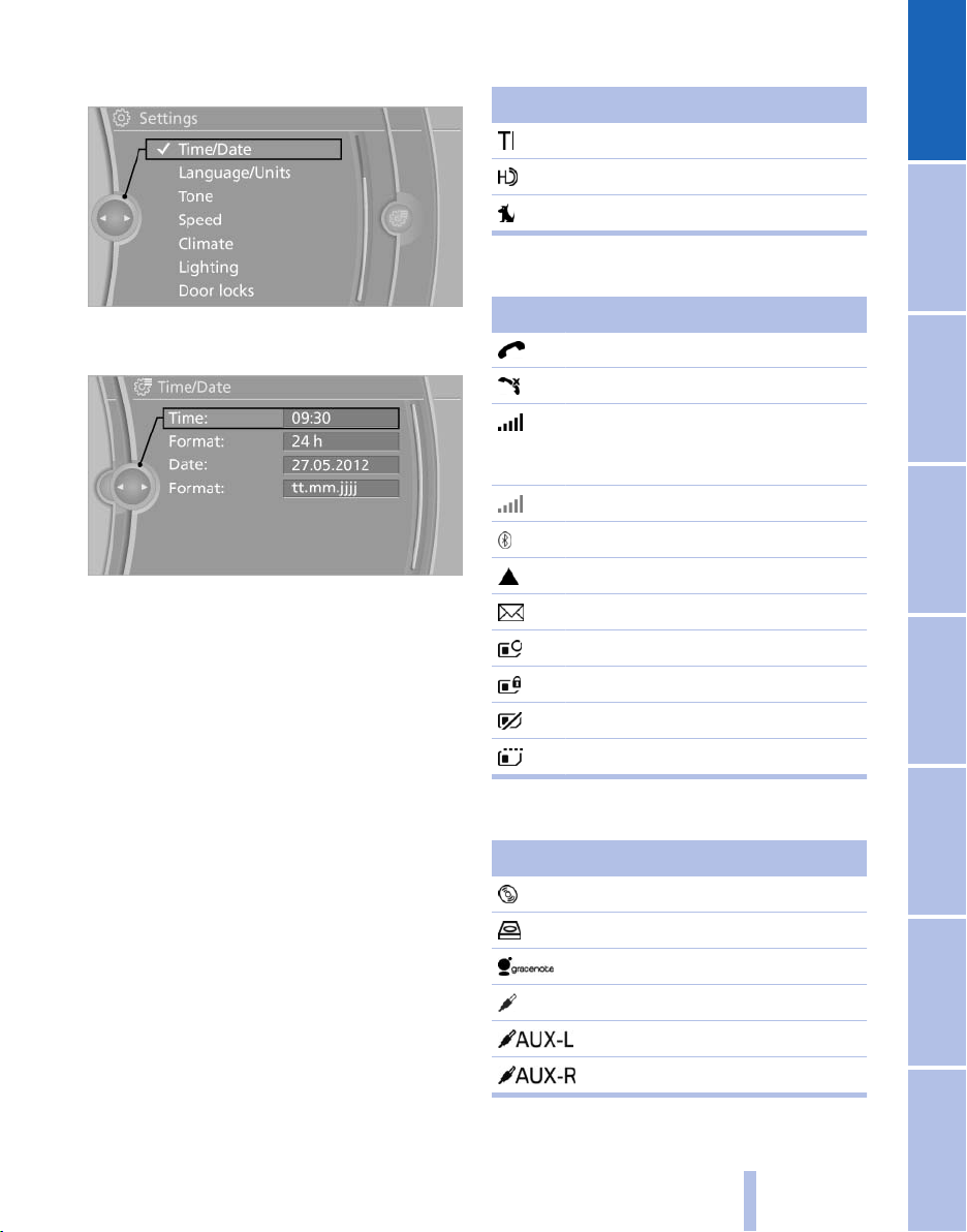
4. Turn the controller until "Time/Date"
lighted, and then press the controller.
5. Turn the controller until "Time:" is high‐
lighted, and then press the controller.
6. Turn the controller to set the hours and
press the controller.
7. Turn the controller to set the minutes and
press the controller.
is high‐
Radio symbols
Symbol Meaning
Traffic bulletins* are switched on.
HD Radio™* is switched on.
Satellite radio* is switched on.
Telephone symbols
Symbol Meaning
Incoming or outgoing call*.
Missed call*.
Wireless network reception
strength*
for network.
Wireless network is not available*.
Bluetooth* is switched on.
Roaming* is active.
Text message* was received.
Check the SIM card*.
SIM card* is blocked.
Symbol flashes: searching
Status information
Status field
following information is displayed in the sta‐
The
tus field at the top right:
▷ Time.
▷ Current entertainment source.
▷ Sound output, on/off.
▷ Wireless network reception strength.
▷ Telephone status.
▷ Traffic bulletin reception*.
Status field symbols
The symbols are grouped as follows.
Online Edition for Part no. 01 40 2 606 469 - 03 11 490
SIM card* is missing.
Enter the PIN*.
Entertainment symbols
Symbol Meaning
CD/DVD* player.
Music collection*.
Gracenote® database*.
AUX-IN port.
Rear AUX-IN port on the left*.
Rear AUX-IN port on the right*.
19
Reference Mobility Communication Entertainment Navigation Driving tips Controls At a glance
Page 20
Symbol Meaning
USB audio interface*.
iDrive
Mobile phone audio interface*.
Additional symbols
Symbol Meaning
Spoken instructions* are switched
off.
Request of the current vehicle posi‐
tion*.
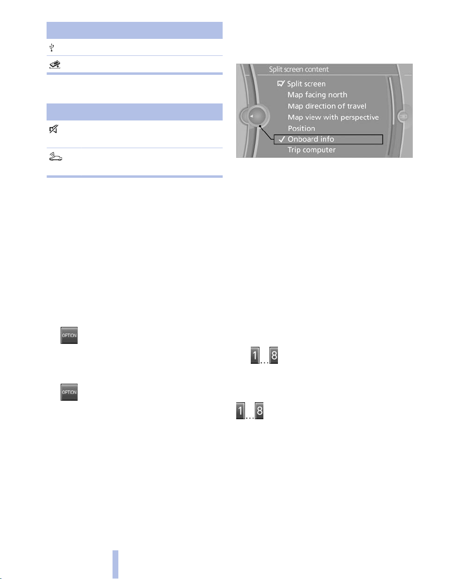
Split screen*
4. Press the controller or select "Split screen
content".
5. Select the desired menu item.
Programmable memory buttons
General information
Additional information can be displayed on the
right side of the split screen, e.g., information
from the computer.
In the divided screen view, the so-called split
screen, this information remains visible even
when you change to another menu.
Switching the split screen on and off
1. Press the button.
2. "Split screen"
Selecting the display
1. Press the button.
2. "Split screen"
3. Move the controller until the split screen is
selected.
General information
The iDrive functions can be stored on the pro‐
grammable memory buttons and called up di‐
rectly, e.g., radio stations, navigation destina‐
tions, phone numbers and entry points into the
menu.
The settings are stored for the remote control
currently in use.
Saving a function
1. Highlight the function via the iDrive.
2.
Press the desired button for more
than 2 seconds.
Running a function
Press the button.
The function will run immediately. This
means, for example, that the number is dialed
when a phone number is selected.
Displaying the button assignment
Use a finger to touch the buttons. Do not wear
gloves or use objects.
key assignment is displayed at the top edge
The
of the screen.
20
Online Edition for Part no. 01 40 2 606 469 - 03 11 490
Page 21
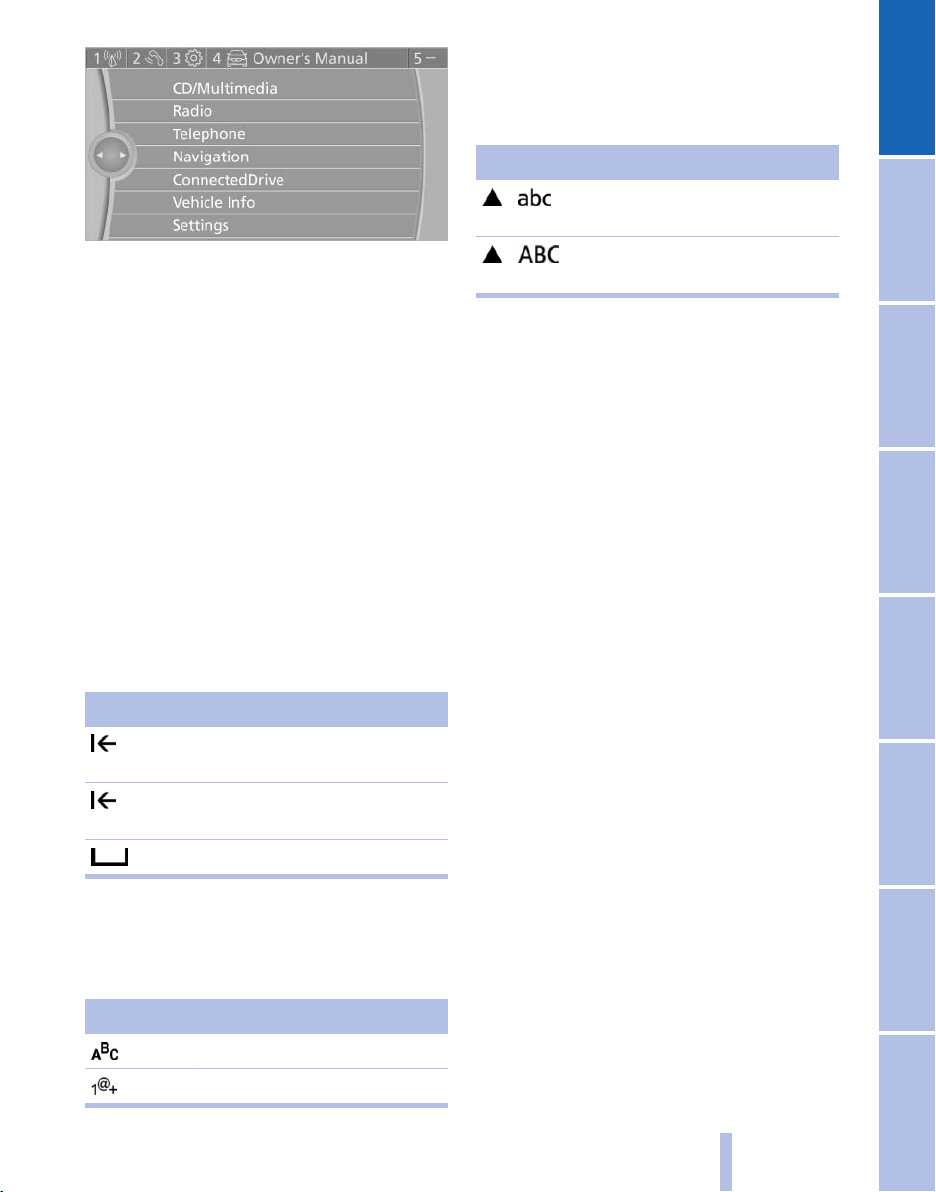
Switching between upper and lower
case letters
Depending on the menu, you can switch be‐
tween entering upper and lower case letters:
Symbol Function
Move the controller up: switch
from upper to lower case letters.
▷ To display short information: touch the but‐
ton.
▷ To display detailed information: touch the
button for an extended period.
Deleting the button assignments
1. Press buttons 1 and 8 simultaneously for
approx. five seconds.
2. "OK"
Entering letters and numbers
1. Turn the controller: select letters or num‐
bers.
2. Select additional letters or numbers if
needed.
3. "OK": confirm the entry.
Symbol Function
Press the controller: delete the letter
or number.
Press the controller for an extended
period: delete all letters or numbers.
Move the controller up: switch
from lower to upper case letters.
Entry comparison
Entry of names and addresses: the selection is
narrowed
letters may be added automatically.
The entries are continuously compared to the
data stored in the vehicle.
▷ Only those letters are offered during the en‐
▷ Destination search: town/city names can be
down every time a letter is entered and
try for which data is available.
entered
able on the Control Display.
using the spelling of language avail‐
Enter a blank space.
Switching between letters and
numbers
Depending on the menu, you can switch be‐
tween entering letters and numbers:
Symbol Function
Enter the letters.
Enter the numbers.
Online Edition for Part no. 01 40 2 606 469 - 03 11 490
21
Reference Mobility Communication Entertainment Navigation Driving tips Controls At a glance
Page 22

Voice activation system*
The concept
▷ The voice activation system can be used to
operate
mands.
▷ Most menu items on the Control Display can
be voiced as commands. The system
prompts you to make your entries.
▷ Functions that can only be used when the
vehicle is stationary cannot be operated us‐
ing the voice activation system.
▷ The system uses a special microphone on
the driver's side.
▷ ›...‹ Verbal instructions in the Owner's
Voice activation system
Manual to use with the voice activation sys‐
tem.
functions by means of spoken com‐
Requirements
Via the Control Display, set a language that is
also supported by the voice activation system
that the spoken commands can be identified.
so
Set the language, refer to page 79.
Using voice activation
Activating the voice activation system
1.
2. Wait for the signal.
3. Say the command.
This symbol in the instrument cluster indi‐
cates that the voice activation system is active.
If no other commands are available, continue
operating the function via iDrive.
Press the button on the steering
wheel.
command is displayed in the instrument
The
cluster.
Terminating the voice activation
system
Briefly press the button on the steering wheel
or ›Cancel‹.
Possible commands
Having possible commands read aloud
The commands available in each case depend
on the menu item selected on the Control Dis‐
play.
To have the available commands read out
loud: ›Voice commands‹
example, if the "Settings" menu is displayed,
For
the commands for the settings are read out loud.
Help dialog for the voice activation
system
Calling up help dialog: ›Help‹
Additional commands for the help dialog:
▷ ›Help with examples‹: information about the
current operating options and the most im‐
portant
commands for them are announced.
▷ ›Help with voice activation‹: information
about the principle of operation for the voice
activation system is announced.
Executing functions using short
commands
Functions on the main menu can be performed
directly
tive of which menu item is currently selected,
e.g., ›Vehicle status‹.
List of short commands of the voice activation
system, refer to page 285.
by means of short commands, irrespec‐
22
Online Edition for Part no. 01 40 2 606 469 - 03 11 490
Page 23
Example: playing back a CD
1. Switch on the Entertainment sound output
if necessary.
2.
3. ›C D and multimedia‹
4. Press the button on the steering
5. ›C D track ...‹ e.g., CD track 4.
Press the button on the steering
wheel.
The medium last played is played back.
wheel.
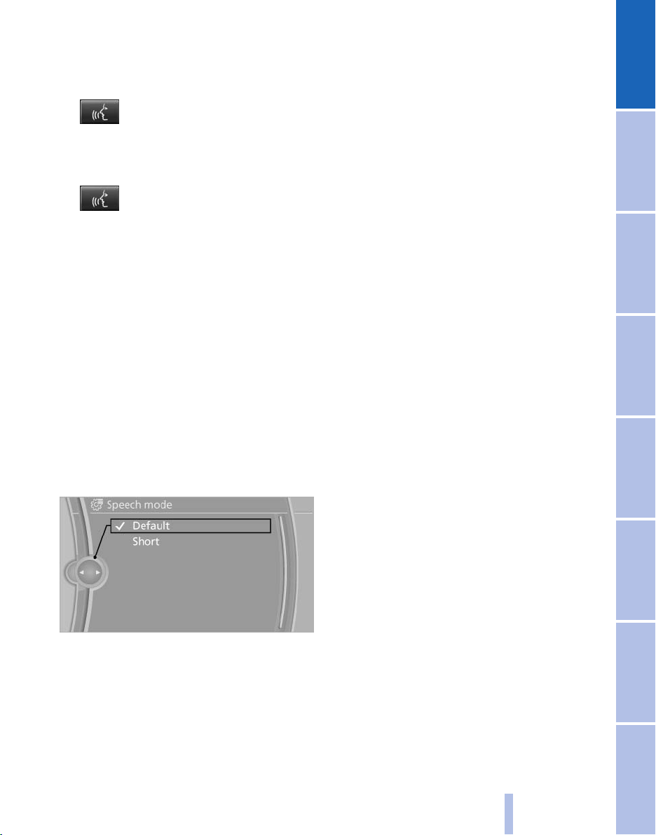
Setting the voice dialog
can set whether the system should use the
You
standard dialog or a shorter version.
In the shorter variant of the voice dialog, the an‐
nouncements from the system are issued in an
abbreviated form.
On the Control Display:
1. "Settings"
2. "Language/Units"
3. "Speech mode:"
4. Select the setting.
▷ The volume is stored for the remote control
currently in use.
Notes on Emergency Requests
Do not use the voice activation system to initiate
an Emergency Request. In stressful situations,
the voice and vocal pitch can change. This can
unnecessarily delay the establishment of a tel‐
ephone connection.
Instead, use the SOS button*, refer to
page 269, in the vicinity of the interior mirror.
Environmental conditions
▷ Say the commands, numbers, and letters
smoothly and with normal volume, empha‐
sis, and speed.
▷ Always say commands in the language of
the voice activation system.
▷ When selecting a radio station, use the com‐
mon pronunciation of the station name.
▷ Keep the doors, windows, and glass sun‐
roof* closed to prevent noise interference.
▷ Avoid making other noise in the vehicle
while speaking.
Adjusting the volume
Turn
the volume button while giving an instruc‐
tion until the desired volume is set.
▷ The volume remains constant even if the
volume of other audio sources is changed.
Online Edition for Part no. 01 40 2 606 469 - 03 11 490
23
Reference Mobility Communication Entertainment Navigation Driving tips Controls At a glance
Page 24
Integrated Owner's Manual in the vehicle
The integrated Owner's Manual can be dis‐
played on the Control Display. The equipment
and functions that are in the vehicle are descri‐
bed therein.
▷ "Owner's Manual"
Components of the integrated Owner's Manual
The integrated Owner's Manual consists of
three parts, which offer various levels of infor‐
mation or access possibilities.
Quick Reference Guide
Located
formation for the operation of the vehicle, the
operation of basic vehicle functions or for what
to do in the event of a flat tire. This information
can also be displayed during driving.
in the Quick Reference is important in‐
Search by pictures
Information and descriptions based on illustra‐
tions can be searched via search by pictures.
This is helpful, for example, if the description of
an outfitting package that cannot be named is
needed.
Owner's Manual
Information and descriptions can be searched
Integrated Owner's Manual in the vehicle
by direct entry of a search term via the index.
Leafing through the Owner's Manual
Page by page with link access
Turn the controller until the next or previous
page is displayed.
Page by page without link access
Leaf through the pages directly while skipping
the links.
Highlight the symbol once. Now simply press
the controller to leaf from page to page.
Leaf back.
Leaf forward.
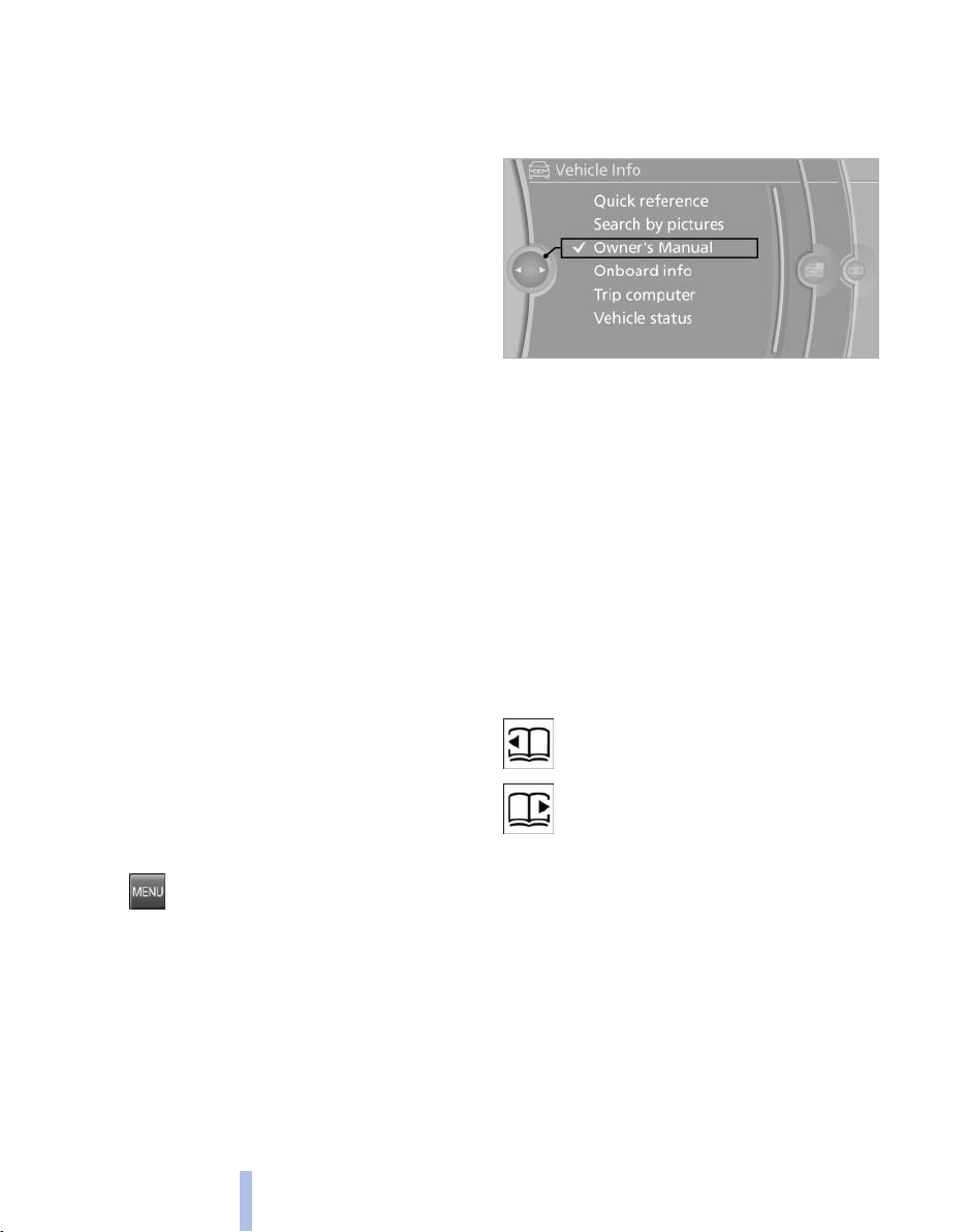
Select components
1.
2. Turn the controller: open "Vehicle Info".
3. Press the controller.
4. Selecting desired range:
Press the button.
▷ "Quick reference"
▷ "Search by pictures"
24
Online Edition for Part no. 01 40 2 606 469 - 03 11 490
Context help - Owner's Manual to the temporarily selected function
The
relevant information can be opened directly.
Opening during operation via iDrive
To move directly from the application on the
Control Display to the options menu:
Page 25

1. Press the button or move the controller
to the right repeatedly until the
menu is displayed.
2. "Display Owner's Manual"
"Options"
Storing
1. Select "Owner's Manual" via the iDrive.
2. Press the desired button for more
than 2 seconds.
Opening when a Check Control
message is displayed
Directly
Control Display:
"Display Owner's Manual"
from the Check Control message on the
Changing between a function and the
Owner's Manual
To change from a function, e.g., radio, to the
Owner's Manual on the Control Display and to
switch between the two displays:
1.
2. "Display Owner's Manual"
3. Select the desired page in the Owner's
4.
5.
To switch back and forth repeatedly between
the function displayed last and the page of the
Owner's Manual displayed last, repeat steps 4
and 5. This opens a new panel every time.
Press the button or move the controller
to the right repeatedly until the
menu is displayed.
Manual.
the button again to return to the
Press
function displayed last.
Press the button to return to the page
of the Owner's Manual displayed last.
"Options"
Executing
Press the button.
The Owner's Manual is displayed im‐
mediately.
Programmable memory buttons
General information
The Owner's Manual can be stored on the pro‐
grammable memory buttons and called up di‐
rectly.
Online Edition for Part no. 01 40 2 606 469 - 03 11 490
25
Reference Mobility Communication Entertainment Navigation Driving tips Controls At a glance
Page 26
Online Edition for Part no. 01 40 2 606 469 - 03 11 490
Page 27

Controls
This chapter is intended to provide you with
information that will give you complete control of
your vehicle. All features and accessories that are
useful for driving and your safety, comfort and
convenience are described here.
Online Edition for Part no. 01 40 2 606 469 - 03 11 490
Page 28
Opening and closing
Remote control/key
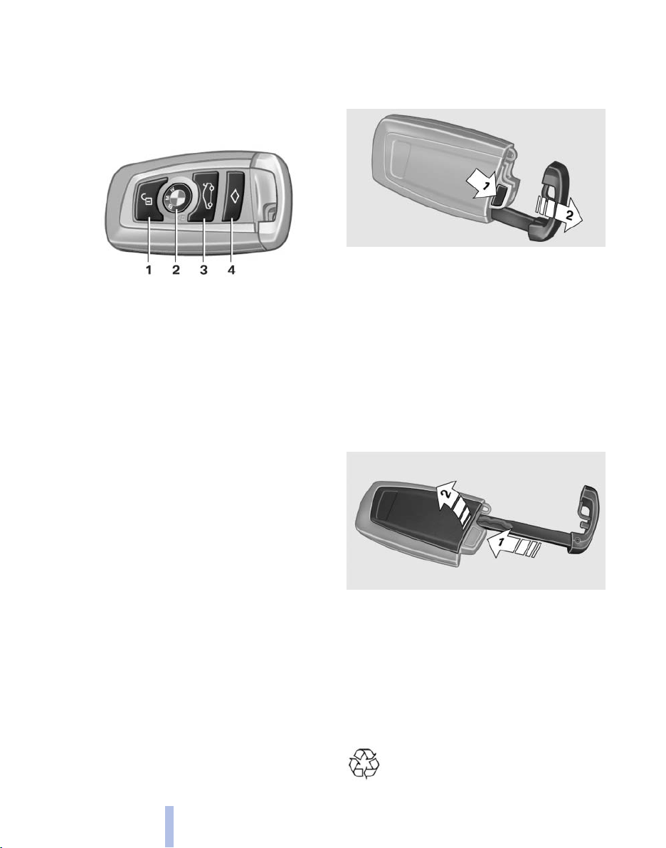
Buttons on the remote control
Opening and closing
1 Unlocking
2 Locking
3 Trunk lid
4 Panic mode*, headlamp courtesy delay fea‐
ture
General information
vehicle is supplied with two remote controls
The
with keys.
Every remote control contains a replaceable
battery.
The settings called up and implemented when
the vehicle is unlocked depend on which remote
control is used to unlock the vehicle, Personal
Profile, refer to page 29.
In addition, information about service require‐
ments is stored in the remote control, Service
data in the remote control, refer to page 260.
Integrated key
Press the button on the back of the remote con‐
trol, arrow 1, and pull out the key, arrow 2.
The integrated key fits the following locks:
▷ Driver's door.
▷ Storage compartment in the front center
armrest.
The storage compartment contains a switch for
separately securing the trunk lid, refer to
page 37.
Replacing the battery
1. Take the integrated key out of the remote
control.
2. Push in the catch with the key, arrow 1.
3. Remove the cover of the battery compart‐
ment; see arrow 2.
4. Insert a battery of the same type with the
positive side facing upwards.
5. Press the cover closed.
Take the used battery to a recycling cen‐
ter or to your service center.
28
Online Edition for Part no. 01 40 2 606 469 - 03 11 490
Page 29

New remote controls
You can obtain new remote controls from your
service center.
Loss of the remote controls
Lost remote controls can be blocked by your
service center.
Emergency
It is possible to switch on the ignition or start the
engine in situations such as the following:
▷ Interference of radio transmission to remote
control by external sources.
▷ Discharged battery in the remote control.
A Check Control message is displayed if an at‐
tempt is made to switch on the ignition or start
the engine.
detection of remote control
Starting the engine in case of
emergency
detection of remote control
Personal Profile
The concept
Personal Profile concept
You can set several of your vehicle's functions
to suit your personal needs and preferences.
▷ The settings are automatically saved in the
profile currently activated.
▷ When the vehicle is unlocked, the profile that
was last detected and called up with the re‐
mote control is used.
▷ Your personal settings will be recognized
and called up again even if the vehicle has
used in the meantime by someone else
been
with another remote control.
The individual settings are stored for three Per‐
sonal Profiles and one guest profile.
Transmitting the settings
Your personal settings can be taken with you to
another vehicle equipped with the Personal Pro‐
file function. For more information, contact your
service center.
Transmission takes place via:
▷ The USB interface*, refer to page 138, in
the glove compartment onto a USB device.
Automatic transmission: if a corresponding
Check Control message appears, hold the re‐
control, as shown, against the marked area
mote
on the steering column and press the Start/Stop
button within 10 seconds while pressing the
brake.
Manual transmission: if a corresponding Check
Control message appears, hold the remote con‐
trol, as shown, against the marked area on the
steering column and press the Start/Stop button
within 10 seconds while pressing the clutch.
Online Edition for Part no. 01 40 2 606 469 - 03 11 490
Profile management
Opening the profiles
different profile can be called up than the one
A
associated with the remote control currently in
use.
1. "Settings"
29
Reference Mobility Communication Entertainment Navigation Driving tips Controls At a glance
Page 30
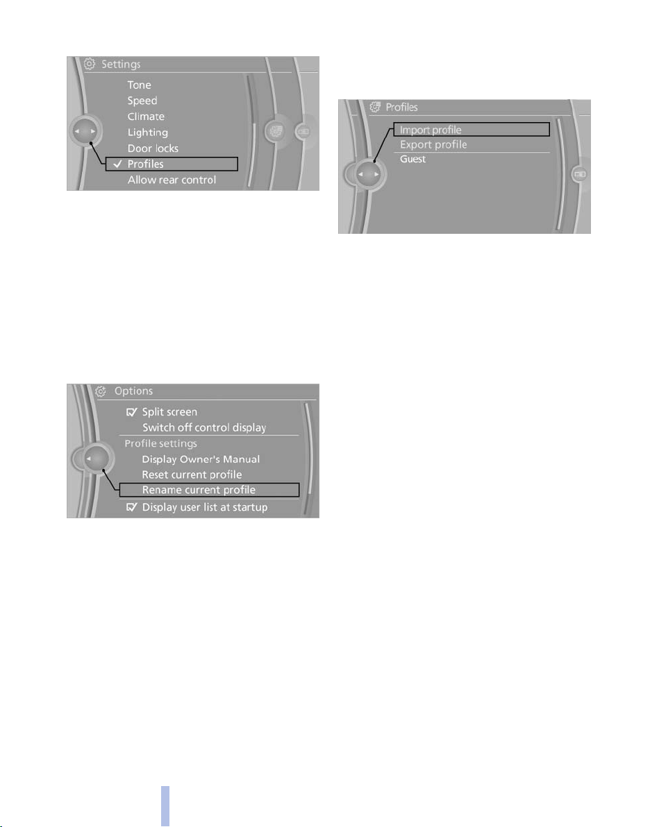
2. "Profiles"
3. Select a profile.
The profile that is opened is assigned to the re‐
mote control currently in use.
Renaming profiles
Opening and closing
1. "Settings"
2. "Profiles"
The current profile is selected.
3. Open "Options".
4. "Rename current profile"
1. "Settings"
2. "Profiles"
3. "Import profile"
4. USB interface, refer to page 138: "USB
device"
Exporting profiles
settings of the active profile and the saved
Most
contacts can be exported.
This can be useful for storing and opening per‐
sonal settings, for instance if settings are acci‐
dentally changed or deleted.
1. "Settings"
2. "Profiles"
3. "Export profile"
4. USB interface, refer to page 138: "USB
device"
Resetting profiles
The settings of the active profile are reset to
their default values.
1. "Settings"
2. "Profiles"
The current profile is selected.
3. Open "Options".
4. "Reset current profile"
Importing profiles
Existing settings and contacts are overwritten
with the imported profile.
30
Online Edition for Part no. 01 40 2 606 469 - 03 11 490
Using the guest profile
The guest profile can be used to make individual
settings without affecting the three Personal
Profiles.
This can be useful for drivers who are using the
vehicle temporarily and do not have their own
profile.
1. "Settings"
2. "Profiles"
3. The current profile is selected.
4. Open "Guest".
5. Create the settings.
Note: the guest profile cannot be renamed.
Page 31

Display profile list during start
The profile list can be displayed during each
start for selecting the desired profile.
1. "Settings"
2. "Profiles"
3. Open "Options".
4. "Display user list at startup"
Personal Profile settings
The following functions and settings can be
stored in a profile.
More information on the settings can be found
under:
▷ Active Cruise Control: collision warning, re‐
fer to page 108.
▷ Exterior mirror position, refer to page 51.
▷ CD/Multimedia, refer to page 181: audio
source listened to last.
▷ Dynamic Driving Control: sport program, re‐
fer to page 99.
▷ Driver's seat position, refer to page 33: au‐
tomatic retrieval after unlocking.
▷ Programmable memory buttons, refer to
page 20: assignment.
▷ Head-up Display, refer to page 124: selec‐
tion, brightness and position of the display.
▷ Headlamp courtesy delay feature, refer to
page 80: time setting.
▷ Tone, refer to page 172: tone settings.
▷ Automatic climate control, refer to
page 126: settings.
▷ Steering wheel position, refer to page 53
▷ Navigation, refer to page 154: map views,
route criteria, voice output on/off.
▷ Night Vision with pedestrian detection, refer
to
page 122: selection of functions and type
of display.
▷ Daytime running lights*, refer to page 81:
current setting.
▷ Park Distance Control PDC, refer to
page 173: adjusting the signal tone volume.
▷ Radio, refer to page 174: stored stations,
station listened to last, special settings.
▷ Backup camera, refer to page 113: selec‐
tion of functions and type of display.
▷ Side View, refer to page 117: selection of
the display type.
▷ Language on the Control Display, refer to
page 79.
▷ Lane departure warning, refer to page 91:
last setting, on/off.
▷ Active Blind Spot Detection, refer to
page 92: last setting, on/off.
▷ Triple turn signal activation, refer to
page 62.
▷ Locking the vehicle, refer to page 35: after
a brief period or after starting to drive.
Central locking system
The concept
The central locking system becomes active
when the driver's door is closed.
The system simultaneously engages and re‐
leases the locks on the following:
▷ Doors.
▷ Trunk lid.
▷ Fuel filler flap.
Operating from the outside
▷ Via the remote control.
▷ Via the driver's door lock*.
▷ Via the door handles*.
▷ Via the button in the trunk lid*.
The following takes place simultaneously when
locking/unlocking the vehicle via the remote
control:
▷ Anti-theft protection is switched on/off.
Doors cannot be unlocked using the lock
buttons or the door opener.
▷ The welcome lamps, interior lamps and
courtesy lamps* are switched on and off.
Online Edition for Part no. 01 40 2 606 469 - 03 11 490
31
Reference Mobility Communication Entertainment Navigation Driving tips Controls At a glance
Page 32

▷ The alarm system*, refer to page 39, is
armed or disarmed.
Operating from the inside
Via the button for the central locking system.
If the vehicle has been locked from inside, the
Opening and closing
fuel filler flap remains unlocked.
If an accident of a certain severity occurs, the
central locking system unlocks automatically.
The hazard warning system and interior lamps
come on.
Opening
and closing: from the
outside
Using the remote control
3. "Unlock button:"
4. Select the desired function:
▷ "Driver's door only"
Only the driver's door and the fuel filler
flap are unlocked. Pressing again un‐
locks the entire vehicle.
▷ "All doors"
The entire vehicle is unlocked.
Convenient opening
The remote control can be used to simultane‐
open the windows and the glass sunroof*.
ously
Press and hold the button on the re‐
mote control.
The windows and the glass sunroof* open.
Releasing the button stops the motion.
General information
Take the remote control with you
People or animals left unattended in a
parked vehicle can lock the doors from the in‐
side. Always take the remote control with you
when leaving the vehicle so that the vehicle can
then be opened from the outside.◀
Unlocking
Press the button.
The vehicle is unlocked.
You can set how the vehicle is to be unlocked.
The setting is stored for the remote control cur‐
rently in use.
1. "Settings"
2. "Door locks"
32
Online Edition for Part no. 01 40 2 606 469 - 03 11 490
Locking
Press the button on the remote control.
Do not lock from the outside
Do not lock the vehicle from the outside if
there are people in it, as the vehicle cannot be
unlocked from inside without special knowl‐
edge.◀
Switching on the interior lamps,
courtesy lamps*, and welcome lamps
Press the button on the remote control
with the vehicle locked.
Panic mode*
You can trigger the alarm system if you find
yourself in a dangerous situation.
Page 33

Press the button on the remote control
for at least 3 seconds.
To switch off the alarm: press any button.
Switching on the headlamp courtesy
delay feature
Briefly press the button on the remote
control.
The duration can be set in the Control Display.
Opening the trunk lid
the button on the remote control
Press
for approx. 1 second and release.
The trunk lid opens, regardless of whether it was
previously locked or unlocked.
During opening, the trunk lid pivots back and up.
Ensure that adequate clearance is available be‐
fore opening.
In some vehicle equipment variants, the trunk lid
can only be opened using the remote control if
the vehicle was unlocked first.
To avoid locking yourself out of the vehicle, do
not place the remote control into the cargo area.
The trunk lid is locked again as soon as it is
pushed closed.
Retrieving the seat, mirror, and
steering wheel settings
The driver's seat, exterior mirror, and steering
wheel positions selected last are stored for the
currently used remote control.
When the vehicle is unlocked, these positions
are automatically retrieved if this function was
activated.
Pinch hazard when moving back the seat
If
this function is used, first make sure that
the footwell behind the driver's seat is empty.
Otherwise, people can be injured or objects
damaged when the seat is moved back.◀
The adjustment procedure is interrupted:
▷ When a seat position switch is pressed.
▷ When a button of the seat, mirror, and steer‐
ing wheel memory is pressed briefly.
Activating the setting
1. "Settings"
2. "Door locks"
3. "Last seat position auto."
Confirmation signals from the vehicle
1. "Settings"
2. "Door locks"
3. Deactivate or activate the desired confirma‐
tion signals.
▷ "Acoustic sig. lock/unlock"
▷ "Flash when lock/unlock"
Online Edition for Part no. 01 40 2 606 469 - 03 11 490
Malfunction
If the vehicle can no longer be locked or un‐
locked
with the remote control, the battery may
be discharged or there may be interference from
external sources such as mobile phones, metal
objects, overhead power lines, transmission
towers, etc.
If this occurs, unlock or lock the vehicle at the
door lock using the key.
33
Reference Mobility Communication Entertainment Navigation Driving tips Controls At a glance
Page 34

For US owners only
The transmitter and receiver units comply with
part 15 of the FCC/Federal Communication
Commission
by the following:
FCC ID:
▷ LX8766S.
▷ LX8766E.
▷ LX8CAS.
▷ LX8CAS2.
▷ MYTCAS4.
Compliance statement:
This device complies with part 15 of the FCC
Rules. Operation is subject to the following two
Opening and closing
conditions:
▷ This device may not cause harmful interfer‐
ence, and
▷ this device must accept any interference re‐
ceived, including interference that may
cause undesired operation.
Any unauthorized modifications or changes to
these devices could void the user's authority to
operate this equipment.
regulations. Operation is governed
Using the door lock
General information
Remove the key before pulling the door
handle
Before pulling the outside door handle, remove
key to avoid damaging the paintwork and the
the
key.◀
In some country-specific versions, the alarm
system* is triggered if the vehicle is unlocked via
the door lock.
Manual operation
If an electrical malfunction occurs, lock or unlock
the vehicle using a key via the door lock on the
driver's door.
Locking the doors and trunk lid at
once*
In some vehicle equipment versions, only the
driver's door can be locked via the door lock.
To lock all doors and the trunk lid at once:
1. With the doors closed, lock the vehicle using
the button for the central locking system in
the interior.
2. Unlock and open the driver's or front pas‐
senger door.
3. Lock the vehicle.
▷ Lock the driver's door using the
integrated key in the door lock, or
▷ Press down the lock button of the front
passenger door and close the door from
the outside.
The fuel filler flap can only be locked using the
remote control.
Do not lock from the outside
not lock the vehicle from the outside if
Do
there are people in it, as the vehicle cannot be
unlocked from inside without special knowl‐
edge.◀
34
Online Edition for Part no. 01 40 2 606 469 - 03 11 490
Page 35

Opening and closing: from the inside
Unlocking and opening*
▷ Either unlock the doors together using the
button for the central locking system and
then
pull the door handle above the armrest
or
▷ Pull the door opener twice individually on
each door: the first time unlocks the door,
the second time opens it.
Locking and unlocking
Press the button in the vehicle.
The doors and the trunk lid are locked
unlocked when the front doors are closed, but
or
they are not secured against theft.
The fuel filler flap remains unlocked.
Automatic locking
The setting is stored for the remote control cur‐
rently in use.
1. "Settings"
2. "Door locks"
3. Select the desired function:
▷ "Lock if no door is opened"
The vehicle locks automatically after a
short period of time if a door is not
opened.
▷ "Lock after start. to drive"
The vehicle locks automatically after
you drive away.
Doors
Automatic Soft Closing*
To close the doors, push lightly.
It is closed automatically.
Danger of pinching
Make sure that the closing path of the
doors is clear; otherwise, injuries may result.◀
Trunk lid
Opening
During
opening, the trunk lid pivots back and up.
Ensure that adequate clearance is available be‐
fore opening.
Opening from the outside
▷ Press the button on the trunk lid.
▷ Press the button on the remote
for approx. 1 second and re‐
control
lease.
Online Edition for Part no. 01 40 2 606 469 - 03 11 490
35
Reference Mobility Communication Entertainment Navigation Driving tips Controls At a glance
Page 36

Opening from the inside
Push
the button in the driver's footwell.
If the vehicle is stationary, the trunk lid opens if
it is not locked.
Closing
Opening and closing
Recessed grips in the interior trim of the trunk
lid make it easier to pull down the lid.
Danger of pinching
Make sure that the closing path of the
lid is clear; otherwise, injuries may result.◀
trunk
Do not place the remote control in the
cargo area
Take the remote control with you and do not
leave it in the cargo area; otherwise, the remote
control may be locked inside the vehicle when
the trunk lid is closed.◀
Automatic trunk lid operation*
Opening
The trunk lid opens fully.
▷ Press the button on the exterior of the trunk
lid.
▷ Press the button on the remote
control or in the driver's footwell.
Pressing the button again stops the motion.
The opening process is interrupted as well:
▷ When starting the engine.
▷ When the vehicle starts moving.
▷ By pressing the button in the driver's foot‐
well.
▷ By pressing the button on the inside of the
trunk lid.
Closing
Locking the vehicle*
Press the button on the inside of the trunk lid.
The vehicle is locked completely.
36
Online Edition for Part no. 01 40 2 606 469 - 03 11 490
▷ Press the button on the inside of the trunk
lid.
The trunk lid closes automatically.
Pressing again stops the motion.
Page 37

With Comfort Access:
▷ Press the button, arrow 1, on the inside of
the trunk lid.
The trunk lid closes automatically.
Pressing again stops the motion.
▷ Press the button, arrow 2.
The trunk lid closes automatically and the
vehicle is locked.
Manual operation
In the event of an electrical fault, manually op‐
erate the unlocked trunk lid slowly and
smoothly.
Locking separately
The
trunk lid can be locked separately using the
switch in the front center armrest.
▷ Trunk lid secured, arrow 1.
▷ Trunk lid not secured, ar‐
row 2.
Slide the switch into the arrow 1 position. This
secures
central locking system.
When the center armrest is locked, the tailgate
cannot be accessed. This is beneficial when the
vehicle is parked using valet service. The infra‐
red remote control can be handed out without
the key.
the trunk lid and disconnects it from the
Emergency unlocking*
▷ Press the button on the exterior of the trunk
lid.
Pressing again stops the motion.
The closing operation is interrupted:
▷ When starting the engine.
▷ The vehicle starts off with jerks.
Danger of pinching
Make sure that the closing path of the
lid is clear; otherwise, injuries may result.◀
trunk
Do not place the remote control in the
cargo area
Take the remote control with you and do not
leave it in the cargo area; otherwise, the remote
control may be locked inside the vehicle when
the trunk lid is closed.◀
Online Edition for Part no. 01 40 2 606 469 - 03 11 490
Pull the handle inside the cargo area.
The trunk lid unlocks.
Comfort Access*
The concept
The vehicle can be accessed without activating
the remote control.
All you need to do is to have the remote control
with you, e.g., in your jacket pocket.
37
Reference Mobility Communication Entertainment Navigation Driving tips Controls At a glance
Page 38

The vehicle automatically detects the remote
control when it is nearby or in the passenger
compartment.
Comfort Access supports the following func‐
tions:
▷ Unlocking/locking of the vehicle.
▷ Convenient closing.
▷ Unlocking of the trunk lid separately.
▷ Starting the engine.
Functional requirements
▷ There are no external sources of interfer‐
ence nearby.
▷ To lock the vehicle, the remote control must
Opening and closing
be located outside of the vehicle.
▷ The next unlocking and locking cycle is not
possible until after approx. 2 seconds.
▷ The engine can only be started if the remote
control is inside the vehicle.
Comparison with ordinary remote
control
functions can be controlled by pressing the
The
buttons or via Comfort Access.
Unlocking
Locking
Press the area on the door handle, arrow 2, with
your finger for approx. 1 second.
This corresponds to pressing the button.
To save battery power, ensure that the ignition
and all electronic systems and/or power con‐
sumers are switched off before locking the ve‐
hicle.
Convenient closing
Press the area, arrow 2, with your finger and
hold.
addition to locking, the windows and the glass
In
sunroof* are closed.
Monitor the closing process
Monitor the closing process to ensure that
no one becomes trapped.◀
Fully grasp a door handle, arrow 1. This corre‐
sponds to pressing the button.
38
Online Edition for Part no. 01 40 2 606 469 - 03 11 490
Unlocking the trunk lid separately
Press the button on the exterior of the trunk lid,
refer to page 35.
This corresponds to pressing the
Do not place the remote control in the
cargo area
Take the remote control with you and do not
it in the cargo area; otherwise, the remote
leave
control may be locked inside the vehicle when
the trunk lid is closed.◀
button.
Malfunction
Comfort Access may not function properly if it
experiences interference from external sources
such as mobile phones, metal objects, overhead
power lines, transmission towers, etc.
Page 39

If this occurs, open or close the vehicle using the
buttons
door lock.
To subsequently start the engine, hold the re‐
mote control against the marked area on the
steering column, refer to page 29.
on the remote control or use a key in the
Alarm system*
The concept
The vehicle alarm system responds to:
▷ Opening of a door, the hood or the trunk lid.
▷ Movements in the vehicle: interior motion
sensor, refer to page 40.
▷ Changes in the vehicle tilt, e.g., during at‐
tempts to steal a wheel or when towing the
car.
▷ Interruptions in battery voltage.
The alarm system briefly indicates tampering:
▷ By sounding an acoustic alarm.
▷ By switching on the hazard warning system.
▷ By flashing the high beams.
In some vehicle equipment variants, the trunk lid
can only be opened using the remote control if
the vehicle was unlocked first.
Panic mode*
the button on the remote control
Press
for at least 3 seconds.
Switching off the alarm
▷ Unlock the vehicle using the remote control.
▷ With Comfort Access: If you are carrying the
remote control with you, pull on the door
handle.
Indicator lamp on the interior rearview
mirror
Arming and disarming the alarm
system
General information
you lock or unlock the vehicle, either with
When
the remote control or at the door lock*, the alarm
system is armed or disarmed at the same time.
Door lock and armed alarm system
Unlocking via the door lock will trigger the alarm
on some country-specific versions.
Trunk lid and armed alarm system
The trunk lid can be opened using the remote
control, even if the alarm system is armed.
Press the button on the remote control
for approx. 1 second and release.
After the trunk lid is closed, it is locked and
monitored again by the alarm system. The haz‐
ard warning system flashes once.
Online Edition for Part no. 01 40 2 606 469 - 03 11 490
▷ The indicator lamp flashes briefly every
2 seconds:
The system is armed.
▷ The indicator lamp flashes after locking:
The doors, hood or trunk lid is not closed
properly, but the rest of the vehicle is se‐
cured.
10 seconds, the indicator lamp flashes
After
continuously. The interior motion sensor is
not active.
▷ The indicator lamp goes out after unlocking:
The vehicle has not been tampered with.
▷ The indicator lamp flashes after unlocking
until the engine is started, but no longer than
approx. 5 minutes:
An alarm has been triggered.
Tilt alarm sensor
The tilt of the vehicle is monitored.
39
Reference Mobility Communication Entertainment Navigation Driving tips Controls At a glance
Page 40

The alarm system responds in situations such
as attempts to steal a wheel or tow the car.
Interior motion sensor
windows and glass sunroof* must be closed
The
for the system to function properly.
Avoiding unintentional alarms
The tilt alarm sensor and interior motion sensor
can be switched off together, such as in the fol‐
lowing situations:
▷ In automatic car washes
▷ In duplex garages.
▷ During transport on car-carrying trains, at
Opening and closing
sea or on a trailer.
▷ When animals are to remain in the vehicle.
Opening
▷
▷ Press the switch beyond the resist‐
Pressing again stops the motion.
Press the switch to the resistance
point.
The window opens while the switch is held.
ance point.
The window opens automatically.
Closing
Danger of pinching
Monitor the closing process and make
that the closing path of the window is clear;
sure
otherwise, injuries may result.◀
Switching off the tilt alarm sensor and
interior motion sensor
Press the button on the remote control
twice in succession.
The indicator lamp lights up for approx. 2 sec‐
onds and then flashes continuously.
tilt alarm sensor and interior motion sensor
The
are switched off until the vehicle is locked again.
Power windows
General information
Take the remote control with you
Take the remote control with you when
leaving the vehicle so that children, for example,
cannot operate the power windows and injure
themselves.◀
▷
The window closes while the switch is held.
▷
point.
The window closes automatically.
Pressing the switch stops the motion.
Convenient operation, refer to page 32, via the
remote control.
Convenient
fort Access*.
the switch to the resistance point.
Pull
Pull the switch beyond the resistance
closing, refer to page 38, with Com‐
Pinch protection
If the closing force exceeds a specific value as a
window closes, the closing action is interrupted.
The window reopens slightly.
Danger of pinching even with pinch pro‐
tection
Even with the pinch protection system, check
that the window's closing path is clear; other‐
wise, the closing action may not stop in certain
situations, e.g., if thin objects are present.◀
Window accessories
Do not install any accessories in the range
of movement of the windows; otherwise, the
pinch protection system will be impaired.◀
40
Online Edition for Part no. 01 40 2 606 469 - 03 11 490
Page 41

Closing without the pinch protection
system
Danger of pinching
Monitor the closing process and make
sure
that the closing path of the window is clear;
otherwise, injuries may result.◀
For example, if there is an external danger or if
ice on the windows prevents a window from
closing normally, proceed as follows:
1. Pull the switch past the resistance point and
hold it there.
Pinch protection is limited and the window
reopens
a certain value.
2. Pull the switch past the resistance point
again within approx. 4 seconds and hold it
there.
The window closes without pinch protec‐
tion.
slightly if the closing force exceeds
Safety switch
The safety switch in the driver's door can be
used to prevent children, for example, from
opening
switches in the rear.
and closing the rear windows using the
Switching on and off
Press the button.
The LED lights up if the safety function
is switched on.
blocked for a limited time to prevent overheat‐
ing. Let the system cool.
The roller sunblind for the rear window cannot
be moved at low interior temperatures.
Driver's door controls
Roller blind for rear window
Press the button.
Roller sunblinds for rear side windows
Pull out the roller sunblind at the loop and hook
it onto the bracket.
Do not open the window while the roller
sunblind is raised.
Do
not open the window while the roller sunblind
is raised; otherwise, there is a risk of damage at
high speeds that may result in personal injury.◀
Glass sunroof, powered*
Safety switch for rear operation
Press the safety switch when transporting
children in the rear; otherwise, injury may result
if the windows are closed without supervision.◀
Roller sunblinds*
General information
If you are no longer able to move the roller sun‐
blind for the rear window after having activated
it a number of times in a row, the system is
Online Edition for Part no. 01 40 2 606 469 - 03 11 490
General information
The glass sunroof and the sliding visor can be
operated together or separately, using the same
switch.
The glass sunroof is operational when the igni‐
tion is switched on.
Danger of pinching
Monitor the closing process and make
sure that the closing path of the glass sunroof is
clear; otherwise, injuries may result.◀
41
Reference Mobility Communication Entertainment Navigation Driving tips Controls At a glance
Page 42

Take the remote control with you
Take the remote control with you when
the vehicle so that children, for example,
leaving
cannot operate the roof and injure themselves.◀
Opening/closing the glass sunroof and
sliding visor together
Briefly press the switch twice in
succession in the desired direc‐
tion past the resistance point.
The glass sunroof and sliding vi‐
sor move together. Pressing the
switch again stops the motion.
Convenient operation, refer to page 32, via the
remote control.
Convenient
fort Access*.
closing, refer to page 38, with Com‐
Tilting the glass sunroof
Opening and closing
Push switch upward briefly.
▷ The closed roof is tilted and
the sliding visor opens
slightly.
▷ The opened roof closes until
it is in its tilted position. The
sliding
visor stays completely
open.
Pressing the switch again
closes the sliding visor al‐
most completely.
Opening/closing the sliding visor
▷ Press the switch in the de‐
sired direction to the resist‐
ance point and hold it there.
The sliding visor moves while
the switch is being held.
▷ Press the switch in the desired direction
past the resistance point.
The sliding visor moves automatically.
Pressing the switch again stops the motion.
Opening/closing the glass sunroof
When the sliding visor is open, proceed as de‐
scribed under Sliding visor.
Pinch protection system
If the closing force when closing the glass sun‐
roof exceeds a certain value, the closing move‐
ment is stopped, beginning at approximately the
middle of the opening in the roof, or from the
tilted position during closing.
The glass sunroof opens again slightly.
Danger of pinching even with pinch pro‐
tection
Despite the pinch protection system, check that
the roof's closing path is clear; otherwise, the
closing action may not be interrupted in certain
extreme situations, such as when thin objects
are present.◀
Closing without the pinch protection
system
For example, if there is an external danger, pro‐
ceed as follows:
1. Press the switch forward beyond the resist‐
ance point and hold.
Pinch protection is limited and the roof re‐
opens
slightly if the closing force exceeds a
certain value.
2. Press the switch forward again beyond the
resistance point and hold until the roof
closes without pinch protection.
42
Online Edition for Part no. 01 40 2 606 469 - 03 11 490
Page 43

Initializing after a power failure
After
a power failure during the opening or clos‐
ing process, the roof can only be operated to a
limited extent.
Initializing the system
The system can be initialized when the vehicle
is stationary and the engine is running.
Danger of pinching
Monitor the closing process and make
sure that the closing path of the glass sunroof is
clear; otherwise, injuries may result.◀
Press the switch up and hold it
until the initialization is complete:
▷ Initialization begins within
15
seconds and is completed
when the sunroof and sliding
visor are completely closed.
▷ The roof closes without pinch protection.
Online Edition for Part no. 01 40 2 606 469 - 03 11 490
43
Reference Mobility Communication Entertainment Navigation Driving tips Controls At a glance
Page 44

Adjusting
Sitting safely
The
ideal seating position can make a vital con‐
tribution to relaxed, fatigue-free driving.
Adjusting
The seating position plays an important role in
an accident in combination with:
▷ Safety belts, refer to page 48.
▷ Head restraints, refer to page 49.
▷ Airbags, refer to page 85.
Seats
Adjusting
General information
Do not adjust the seat while driving
Never attempt to adjust the driver's seat
while driving.
The seat could respond with unexpected move‐
ment and the ensuing loss of vehicle control
could lead to an accident.◀
Do not incline the backrest too far to the
rear
Do not incline the backrest on the front passen‐
ger side too far to the rear during driving. Oth‐
erwise, there is the danger of sliding under the
safety belt in an accident. This would eliminate
the protection normally provided by the belt.◀
The seat setting is stored for the remote control
currently in use. When the vehicle is unlocked
via the remote control, the position is automati‐
cally retrieved if this function, refer to page 33,
was activated.
At a glance: partially powered seats
1 Thigh support*
2 Tilt
3 Forward/backward
4 Lumbar support*
5 Height
6 Backrest
Adjustments in detail: partially
powered seats
Forward/back:
Pull the lever and slide the seat in the desired
direction.
releasing the lever, move the seat forward
After
or back slightly to make sure it engages prop‐
erly.
44
Online Edition for Part no. 01 40 2 606 469 - 03 11 490
Page 45

Seat tilt:
Pull the lever and move the seat to the desired
tilt. After releasing the lever, apply your weight
the seat or lift it off to make sure the seat en‐
to
gages properly.
Overview: Power* seats
1 Lumbar support*
2 Backrest width*
3 Shoulder support*
4 Backrest
5 Forward/back, height, tilt
6 Thigh support*
Adjustments in detail: power* seats
1. Forward/back.
Height:
Move the button in the required direction.
Backrest tilt:
Move the button in the required direction.
Online Edition for Part no. 01 40 2 606 469 - 03 11 490
2. Height.
45
Reference Mobility Communication Entertainment Navigation Driving tips Controls At a glance
Page 46

3. Seat tilt.
Adjusting
4. Backrest tilt.
5. Thigh support*.
▷ Press the front/rear section of the switch.
The curvature is increased/decreased.
▷ Press the upper/lower section of the switch.
The curvature is shifted up/down.
Shoulder support*
Also supports the back in the shoulder area:
▷ Results in a relaxed seating position.
▷ Reduces strain on the shoulder muscles.
Lumbar support*
The curvature of the seat backrest can be ad‐
justed in such a way that it supports the lumbar
region of the spine. The lower back and the
spine are supported for upright posture.
46
Online Edition for Part no. 01 40 2 606 469 - 03 11 490
Active seat*
Active adjustment of the seat cushion's con‐
tours reduces muscular tension and fatigue to
help prevent lower back pain.
Press the button. The LED lights up.
Page 47

Front seat heating*
Switching on
Press
the button once for each temper‐
ature level.
The maximum temperature is reached when
three LEDs are lit.
Switching off
Press the button longer.
The LEDs go out.
The temperature may be reduced or seat heat‐
ing may be switched off entirely to save battery
power.
Temperature distribution*
The heating action in the seat cushion and back‐
rest can be distributed in different ways.
1. "Climate"
2. "Seat heating distribution"
3. Select the required seat.
Rear seat heating*
Switching on
Press
the button once for each temper‐
ature level.
The maximum temperature is reached when
three LEDs are lit.
Switching off
Press the button longer.
The LEDs go out.
Front active seat ventilation*
The seat cushion and backrest surfaces are
cooled by means of integrated fans.
The ventilation rapidly cools the seat, e.g., if the
vehicle interior is overheated or for continuous
cooling at high temperatures.
4. Turn the controller to set the temperature
distribution.
Online Edition for Part no. 01 40 2 606 469 - 03 11 490
Switching on
Press
the button once for each ventila‐
tion level.
The highest level is active when three LEDs are
lit.
47
Reference Mobility Communication Entertainment Navigation Driving tips Controls At a glance
Page 48

After a short time, the system automatically
moves down one level in order to prevent ex‐
cessive cooling.
The safety belt must not lie across the neck, rub
sharp edges, be routed over solid or breaka‐
on
ble objects, or be pinched.◀
Switching off
Press the button longer.
The LEDs go out.
Adjusting
Safety belts
Seats with safety belt
The vehicle has five seats, each of which is
equipped with a safety belt.
Notes
Always make sure that safety belts are being
worn by all occupants before driving away.
Although airbags enhance safety by providing
added protection, they are not a substitute for
safety belts.
▷ The shoulder strap's anchorage point will be
correct for adult seat occupants of every
build if the seat is correctly adjusted.
▷ The two outer safety belt buckles,
integrated
gers sitting on the left and right.
▷ The center rear seat belt buckle marked with
the letters CENTER is solely intended for
the center passenger.
One person per safety belt
Never allow more than one person to wear
a single safety belt. Never allow infants or small
children to ride on a passenger's lap.◀
Putting on the belt
Lay the belt, without twisting, snugly
across the lap and shoulders, as close to the
body as possible. Make sure that the belt lies low
around the hips in the lap area and does not
press on the abdomen. Otherwise, the belt can
slip over the hips in the lap area in a frontal im‐
pact and injure the abdomen.
into the rear seat, are for passen‐
Reduction of restraining effect
Avoid wearing clothing that prevents the
belt from fitting properly, and pull the shoulder
belt periodically to readjust the tension across
your lap; otherwise, the retention effect of the
safety belt may be reduced.◀
Buckling the belt
Make sure you hear the latch plate engage in the
belt buckle.
Unbuckling the belt
1. Hold the belt firmly.
2. Press the red button in the belt buckle.
3. Guide the belt back into its reel.
Safety belt reminder for the driver's and
front passenger seat
The indicator lamp flashes or lights up
and a signal sounds. Make sure that the
safety belts are positioned correctly.
The safety belt reminder is active at speeds
above approx. 5 mph/8 km/h. It can also be ac‐
tivated if objects are placed on the front pas‐
senger seat.
Damage to safety belts
In the case of strain caused by accidents or
damage:
Have the safety belts, including the safety belt
tensioners, replaced and have the belt anchors
checked.
48
Online Edition for Part no. 01 40 2 606 469 - 03 11 490
Page 49

Checking and replacing safety belts
Have the work performed only by your
service center; otherwise, it cannot be ensured
that this safety feature will function properly.◀
Front head restraints
Correctly adjusted head restraint
A correctly adjusted head restraint reduces the
of injury to cervical vertebrae in the event of
risk
an accident.
Adjusting the head restraint
Correctly adjust the head restraints of all
occupied seats; otherwise, there is an increased
risk of injury in an accident.◀
Height
Adjust the head restraint so that its center is ap‐
proximately at ear level.
Distance
Adjust the distance so that the head restraint is
as close as possible to the back of the head.
Adjusting the height: manual head
restraints
▷ To raise: pull.
▷ To lower: press the button, arrow 1, and
push the head restraint down.
Adjusting the height: Electrical* head
restraints
Active head restraint
In the event of a rear-end collision with a certain
severity, the active head restraint automatically
reduces the distance from the head.
Reduced protective function
▷ Do not use seat or head restraint cov‐
ers.
▷ Do not hang objects, e.g., clothes hangers,
on the head restraints.
▷ Only attach accessories approved by BMW
to the seat or head restraint.
Otherwise, the protective function of the active
head restraint will be impaired and the personal
safety of the occupants will be endangered.◀
Online Edition for Part no. 01 40 2 606 469 - 03 11 490
Adjusting electrically.
Distance to back of head: manual head
restraints
▷ Forward: pull.
▷ Back: press the button and push the head
restraint toward the rear.
49
Reference Mobility Communication Entertainment Navigation Driving tips Controls At a glance
Page 50

Distance to the back of the head:
power* head restraints
The
head restraint is automatically repositioned
when the shoulder support is adjusted.
Adjusting the side extensions*
Adjusting
Fold forward for increased lateral support in the
resting position.
Removing
The head restraints cannot be removed.
Rear head restraints
Adjusting the height
▷ To raise: pull.
▷ To lower: press the button, arrow 1, and
push the head restraint down.
Folding forward
Correctly adjusted head restraint
A correctly adjusted head restraint reduces the
of injury to cervical vertebrae in the event of
risk
an accident.
Adjusting the head restraint
Correctly adjust the head restraints of all
occupied seats; otherwise, there is an increased
risk of injury in an accident.◀
Height
Adjust the head restraint so that its center is ap‐
proximately at ear level.
Distance
Adjust the distance so that the head restraint is
as close as possible to the back of the head.
50
Online Edition for Part no. 01 40 2 606 469 - 03 11 490
Press the button, arrow 1, and fold the head re‐
straint forward.
Removing
Only remove the head restraint if no one will be
sitting in the seat in question.
1. Pull the head restraint upward as far as pos‐
sible.
2. Press the button, arrow 1, and pull the head
restraint out completely.
Page 51

Before transporting passengers
Reinstall the head restraint before trans‐
porting anyone in the seat; otherwise, the pro‐
tective function of the head restraint is unavail‐
able.◀
Seat, mirror, and steering
wheel memory*
General information
Front
Two different driver's seat, exterior mirror, and
steering wheel positions can be stored and re‐
for each remote control. The adjustment
trieved
of the lumbar support is not stored.
Comfort function
1. Open the driver's door.
2. Switch off the ignition.
3. Briefly press the desired button 1 or 2.
The corresponding seat position is performed
automatically.
The procedure stops when a switch for adjust‐
ing the seat or one of the buttons is pressed.
Safety mode
1. Close the driver's door or switch on the ig‐
nition.
2. Press and hold the desired button 1 or 2 until
the adjustment procedure is completed.
Calling up of a seat position
deactivated
After
a brief period, the calling up of stored seat
positions is deactivated to save battery power.
To reactivate calling up of a seat position:
▷ Open or close the door or trunk lid.
▷ Press a button on the remote control.
▷ Press the Start/Stop button.
Storing
1. Switch on the ignition.
2. Set the desired position.
3.
4. Press the desired button 1 or 2. The LED
If the M button is pressed accidentally:
Press the button. The LED in the
button lights up.
goes out.
Press the button again.
The LED goes out.
Calling up settings
Do not retrieve the memory while driving
Do not retrieve the memory setting while
driving,
or steering wheel could result in an accident.◀
as an unexpected movement of the seat
Online Edition for Part no. 01 40 2 606 469 - 03 11 490
Mirrors
Exterior mirrors
At a glance
1 Adjusting
2 Left/right, Automatic Curb Monitor*
3 Fold in and out*
51
Reference Mobility Communication Entertainment Navigation Driving tips Controls At a glance
Page 52

General information
The
mirror on the passenger side is more curved
than the driver's side mirror.
Estimating distances correctly
Objects reflected in the mirror are closer
than they appear. Do not estimate the distance
to the traffic behind you based on what you see
Adjusting
in the mirror, as this will increase your risk of an
accident.◀
The mirror setting is stored for the remote con‐
trol currently in use. When the vehicle is un‐
locked via the remote control, the position is au‐
tomatically retrieved if the setting for this
function is active.
Selecting a mirror
To change over to the other mirror:
Slide the mirror changeover switch.
Adjusting electrically
The setting corresponds to the direction
in which the button is pressed.
Storing positions*
Seat, mirror, and steering wheel memory, refer
to page 51.
Adjusting manually
If an electrical malfunction occurs, for example,
press the edges of the mirror glass.
Automatic Curb Monitor*
When the reverse gear is engaged, the mirror
glass tilts downward slightly on the front pas‐
senger side. This improves your view of the curb
and other low-lying obstacles when parking, for
example.
Deactivating
Slide the mirror changeover switch to the pas‐
senger's side mirror position.
Fold in and out*
Press the button.
Possible up to approx. 15 mph/20 km/h.
For example, this is advantageous
▷ In car washes.
▷ In narrow streets.
▷ For folding back mirrors that were folded
away manually.
Mirrors that were folded in are folded out auto‐
matically
fold in the exterior mirrors by hand or with the
button; otherwise, they could be damaged, de‐
pending on the width of the vehicle.◀
at a speed of approx. 25 mph/40 km/h.
Fold in the mirror in a car wash
Before entering an automatic car wash,
Automatic heating
Both exterior mirrors are automatically heated
whenever the engine is running.
Automatic dimming feature
Both exterior mirrors are automatically dimmed.
Photocells are used for control in the Interior rear
view mirror, refer to page 53.
Interior rearview mirror
Reducing the blinding effect
Activating
1.
2. Engage transmission position R.
Slide the mirror changeover switch
to the driver's side mirror position.
52
Online Edition for Part no. 01 40 2 606 469 - 03 11 490
From behind when driving at night: turn the
knob.
Page 53

Interior rearview mirror, automatic
dimming feature
Photocells are used for control:
▷ In the mirror glass.
▷ On the back of the mirror.
For proper operation:
▷ Keep the photocells clean.
▷ Do not cover the area between the inside
rearview mirror and the windshield.
*
Steering wheel
General information
Do not adjust while driving
Do not adjust the steering wheel while
driving; otherwise, an unexpected movement
could result in an accident.◀
Power* steering wheel adjustment
The steering wheel can be adjusted in four di‐
rections.
Storing the position
Seat, mirror, and steering wheel memory, refer
to page 51.
Steering wheel heating
*
Switching on/off
Press the button.
▷ On: the LED lights up.
▷ Off: the LED goes out.
Manual steering wheel adjustment
1. Fold the lever down.
2. Move the steering wheel to the preferred
height and angle to suit your seating posi‐
tion.
3. Fold the lever back.
Online Edition for Part no. 01 40 2 606 469 - 03 11 490
53
Reference Mobility Communication Entertainment Navigation Driving tips Controls At a glance
Page 54

Transporting children safely
The right place for children
Installing child restraint fixing systems
Note
Children in the vehicle
Do not leave children unattended in the
vehicle; otherwise, they could endanger them‐
selves and other persons, e.g., by opening the
doors.◀
Children should always be in the rear
Accident research shows that the safest place
for children is in the back seat.
Transporting children in the rear
Only transport children younger than
13
years of age or shorter than 5 ft/150 cm in the
rear in child restraint fixing systems provided in
accordance with the age, weight and size of the
Transporting children safely
child; otherwise, there is an increased risk of in‐
jury in an accident.
Children 13 years of age or older must wear a
safety belt as soon as a suitable child restraint
fixing system can no longer be used, due to their
age, weight and size.◀
Children on the front passenger seat
Should it ever be necessary to use a child re‐
straint fixing system in the front passenger seat,
make sure that the front, knee and side airbags
on the front passenger side are deactivated. Au‐
tomatic deactivation of front passenger airbags,
refer to page 86.
Deactivating the front passenger airbags
If a child restraint fixing system is used in
the front passenger seat, the front passenger
airbags must be deactivated; otherwise, there is
an increased risk of injury to the child when the
airbags are triggered, even with a child restraint
fixing system.◀
Before mounting
If the rear seat backrests are adjustable:
Before mounting child restraint fixing systems,
return all of the rear seat backrests to the basic
position.
Notes
Manufacturer's information for child re‐
straint fixing systems
To select, mount and use child restraint fixing
systems, observe the information provided by
the system manufacturer; otherwise, the pro‐
tective effect can be impaired.
On the front passenger seat
After installing a child restraint fixing system in
the front passenger seat, make sure that the
front, knee and side airbags on the front pas‐
senger side are deactivated.
Deactivate the front passenger airbags auto‐
matically, refer to page 86.
Deactivating the front passenger airbags
If a child restraint fixing system is used in
the front passenger seat, the front passenger
airbags must be deactivated; otherwise, there is
an increased risk of injury to the child when the
airbags are triggered, even with a child restraint
fixing system.◀
Seat position and height
Before installing a child restraint fixing system,
move the front passenger seat as far back as
possible and adjust its height to the middle po‐
sition to obtain the best possible position for the
belt and to offer optimal protection in the event
of an accident.
Do not change the seat position and height after
this.
◀
54
Online Edition for Part no. 01 40 2 606 469 - 03 11 490
Page 55

Backrest width*
Before
installing a child restraint fixing system in
the front passenger seat, open the backrest
width completely. Do not change the backrest
width again and do not call up a memory posi‐
tion.
Backrest width for the child seat
Before installing a child restraint fixing
system in the front passenger seat, the backrest
width must be opened completely. Do not
change the adjustment after this; otherwise, the
stability of the child seat will be reduced.◀
Child seat security
The rear safety belts and the front passenger
safety belt can be locked against pulling out for
mounting the child restraint fixing systems.
Locking the safety belt
1. Pull out the belt webbing completely.
2. Secure the child restraint fixing system with
the belt.
3. Allow the belt webbing to be pulled in and
pull it taut against the child restraint fixing
system. The safety belt is locked.
LATCH child restraint fixing system
LATCH: Lower Anchors and Tether for CHil‐
dren.
Note
Manufacturer's information for LATCH
child restraint fixing systems
To
mount and use the LATCH child restraint fix‐
ing systems, observe the operating and safety
information from the system manufacturer; oth‐
erwise, the level of protection may be reduced.◀
Mounts for the lower LATCH anchors
Correctly engage the lower LATCH an‐
chors
Make sure that the lower LATCH anchors have
properly engaged and that the child restraint fix‐
ing system is resting snugly against the back‐
rest; otherwise, the degree of protection offered
may be reduced.◀
Before mounting the LATCH child restraint fix‐
ing system, pull the belt away from the child re‐
straint fixing system.
Without a through-loading system:
Position
Unlocking the safety belt
1. Unbuckle the belt buckle.
2. Remove the child restraint fixing system.
3. Allow the belt webbing to be pulled in com‐
pletely.
Online Edition for Part no. 01 40 2 606 469 - 03 11 490
Mounts for the lower LATCH anchors are lo‐
in the gap between the seat and backrest.
cated
55
Reference Mobility Communication Entertainment Navigation Driving tips Controls At a glance
Page 56

With a through-loading system:
Position
Mounts for the lower LATCH anchors are lo‐
cated behind the indicated covers.
Retaining strap guide
Retaining strap
Make sure the upper retaining strap does
not
run over sharp edges and is not twisted as it
passes to the top anchor. Otherwise, the strap
will not properly secure the child restraint fixing
system in the event of an accident.◀
Mounting LATCH child restraint fixing
systems
1. Mount the child restraint fixing system; refer
to the operating instructions of the system.
2. Ensure that both LATCH anchors are prop‐
erly connected.
Transporting children safely
Child restraint fixing systems with a
tether strap
Mounting points
1 Direction of travel
2 Head restraint.
3 Hook for upper retaining strap
4 Mounting point/eye
5 Rear window shelf
6 Seat backrest
7 Upper retaining strap
Depending on the vehicle equipment, there are
two outer or three mounting points for child re‐
straint fixing systems with a tether strap.
LATCH mounting eyes
use the mounting eyes for the upper
Only
LATCH retaining strap to secure child restraint
fixing systems; otherwise, the mounting eyes
could be damaged.◀
56
Online Edition for Part no. 01 40 2 606 469 - 03 11 490
Attaching the upper retaining strap to
the mounting point
1. Remove the mounting point cover.
2. Raise the head restraint. Do not change the
middle head restraint*.
3. Guide the upper retaining strap between the
supports of the head restraint.
it over the head restraint of the middle
Guide
seat.
4. Attach the hooks of the retaining strap to the
mounting eyes.
5. Tighten the retaining strap by pulling it
down.
6. Lower the head restraint.
Page 57

Locking the doors and windows
Rear doors
Push the locking lever on the rear doors down.
The door can now be opened from the outside
only.
Safety switch for the rear
Press the button on the driver's door if
children are being transported in the
rear.
locks various functions so that they cannot
This
be operated from the rear: safety switch, refer to
page 41.
Online Edition for Part no. 01 40 2 606 469 - 03 11 490
57
Reference Mobility Communication Entertainment Navigation Driving tips Controls At a glance
Page 58

Driving
Start/Stop button
Driving
The concept
Pressing the Start/Stop button
switches
starts the engine.
Automatic transmission*: the en‐
gine starts if the brake is de‐
pressed when the Start/Stop button is pressed.
Manual transmission: the engine starts if the
clutch is depressed when the Start/Stop button
is pressed.
Ignition on
Automatic transmission*: press the Start/Stop
button, and do not press on the brake pedal at
the same time.
Manual-shift transmission: press the Start/Stop
button, and do not press on the clutch pedal at
the same time.
All vehicle systems are ready for operation.
Most of the indicator and warning lamps in the
instrument cluster light up for varying lengths of
time.
To save battery power when the engine is off,
switch off the ignition and any unnecessary
electronic systems/power consumers.
The ignition switches off automatically:
▷ When the vehicle is locked, if the low beams
are switched on.
▷ Shortly before the battery is discharged
completely, so that the engine can still be
started.
▷ If the engine is switched off and the ignition
is switched on, the system automatically
switches to the radio ready state when the
door is opened if the lights are switched off
or the daytime running lights are switched
on.
the ignition on or off and
Ignition off
Automatic transmission*: press the Start/Stop
button again, and do not press on the brake
pedal at the same time.
Manual-shift
button again, and do not press on the clutch
pedal at the same time.
All indicator lamps in the instrument cluster go
out.
To save battery power when the engine is off,
switch off the ignition and any unnecessary
electronic systems/power consumers.
When the ignition is switched off, position P is
engaged automatically. When in an automatic
car wash, for example, ensure that the ignition is
not switched off accidentally.◀
When the vehicle is locked using the central
locking system, the ignition switches off auto‐
matically.
transmission: press the Start/Stop
Transmission position P with the ignition
off
Radio ready state
Activate radio ready state:
▷ When the ignition is switched off: press ON/
OFF button on the radio.
▷ When the engine is running: press START/
STOP button.
Some electronic systems/power consumers re‐
main ready for operation.
Radio ready state switches off automatically:
▷ After approx. 8 minutes.
▷ When the vehicle is locked using the central
locking system.
58
Online Edition for Part no. 01 40 2 606 469 - 03 11 490
Page 59

Starting the engine
General information
Enclosed areas
Do not let the engine run in enclosed
areas; otherwise, breathing of exhaust fumes
may lead to loss of consciousness and death.
The
exhaust gases contain carbon monoxide, an
odorless and colorless but highly toxic gas.◀
Unattended vehicle
Do not leave the car unattended with the
engine running; otherwise, it presents a poten‐
tial source of danger.
Before leaving the car with the engine running,
set the parking brake and place the transmission
in position P or neutral to prevent the car from
moving.◀
Frequent starting in quick succession
Avoid repeated futile attempts at starting
the car and avoid starting the car frequently in
quick succession. Otherwise, the fuel is not
burned or is inadequately burned, and there is
the danger of overheating and damaging the
catalytic converter.◀
Do not wait for the engine to warm up while the
vehicle remains stationary. Start driving at mod‐
erate engine speeds.
Manual transmission
Starting the engine
1. Depress the brake pedal.
2. Press on the clutch and shift to neutral.
3. Press the Start/Stop button.
The ignition is activated automatically for a cer‐
tain time and is stopped as soon as the engine
starts.
Automatic transmission
Starting the engine
1. Depress the brake pedal.
2. Press the Start/Stop button.
*
The ignition is activated automatically for a cer‐
tain time and is stopped as soon as the engine
starts.
Engine stop
General information
Take the remote control with you
Take the remote control with you when
the vehicle so that children, for example,
leaving
cannot operate the windows and injure them‐
selves.◀
Set the parking brake and further secure
the vehicle as required
Set the parking brake firmly when parking; oth‐
erwise, the vehicle could roll. On steep upward
and downward inclines, further secure the vehi‐
cle, for example, by turning the steering wheel in
the direction of the curb. ◀
Before driving into a car wash
In order for the vehicle to be able to roll into a car
wash, heed the information regarding Washing
in automatic car washes, refer to page 274.
Manual transmission
Switching off the engine
1. With the vehicle at a standstill, press the
Start/Stop button.
2. Shift into first gear or reverse.
3. Set the parking brake.
Automatic transmission*
Switching off the engine
1. Engage transmission position P with the ve‐
hicle stopped.
2. Press the Start/Stop button.
The engine is switched off.
The radio ready state is switched on.
3. Set the parking brake.
Online Edition for Part no. 01 40 2 606 469 - 03 11 490
59
Reference Mobility Communication Entertainment Navigation Driving tips Controls At a glance
Page 60

Parking brake
The concept
The parking brake is primarily intended to pre‐
vent the vehicle from rolling while parked; it
Driving
brakes the rear wheels.
In cars with automatic transmission*:
The parking brake can be set manually or auto‐
matically:
▷ Manual: by pulling and pushing the switch.
▷ Automatic: by activating Automatic Hold.
Setting
Pull the switch.
The LED lights up.
The indicator lamp lights up in red. The
parking brake is set.
Lower lamp: indicator lamp in Canadian
models
Set the parking brake and further secure
the vehicle as required
Set the parking brake firmly when parking; oth‐
erwise, the vehicle could roll. On steep upward
and
downward inclines, further secure the vehi‐
cle, for example, by turning the steering wheel in
the direction of the curb. ◀
The indicator lamp lights up in red, a sig‐
sounds and the brake lamps light up.
nal
Lower lamp: indicator lamp in Canadian
models
If the vehicle is braked to a speed of approx.
2 mph/3 km/h, the parking brake remains set.
Releasing
Manual transmission: Press the switch
while the brake or clutch is pressed.
Automatic transmission*: Press the switch
while the brake is pressed or transmission po‐
sition P is engaged.
The LED and indicator lamp go out.
The parking brake is released.
Take the remote control with you
Take the remote control with you when
leaving the vehicle so that children, for example,
cannot release the parking brake.◀
Automatic Hold*
The concept
This system assists the driver by automatically
setting and releasing the brake, such as when
moving in stop-and-go traffic.
The vehicle is automatically held in place when
it is stationary.
On inclines, the system prevents the vehicle
from rolling backward when driving away.
While driving
Use while driving:
Pull the switch and hold it. The vehicle brakes
hard while the button is being pulled.
60
Online Edition for Part no. 01 40 2 606 469 - 03 11 490
Page 61

For your safety
Under
the following conditions, Automatic Hold
is automatically deactivated and the parking
brake is set:
▷ The engine is switched off.
▷ A door is opened and driver's safety belt is
unbuckled.
▷ The moving vehicle is brought to a standstill
using the parking brake.
The indicator lamp switches from green
to red and the letters AUTO H go out.
Lower lamp: indicator lamp in Canadian
models
Before driving away:
▷ Release the parking brake manually.
▷ Reactivate Automatic Hold.
Leaving the vehicle with the engine run‐
ning
Before leaving the vehicle with the engine run‐
ning, engage position P of the automatic trans‐
mission
Otherwise, the vehicle may begin to roll.◀
and ensure that the parking brake is set.
Activating
This function can be activated when the driver's
door is closed and the safety belt is fastened, or
while driving.
Press the button.
The LED and the letters AUTO H light
up.
The indicator lamp lights up.
Automatic Hold is activated.
Deactivating
Press the button again.
The LED and the letters AUTO H go
out.
Automatic Hold is deactivated.
If the vehicle is being held by Automatic Hold,
press on the brake pedal to deactivate it.
When the parking brake, refer to page 60, is set
manually, Automatic Hold is deactivated auto‐
matically.
Driving
Automatic
matically secured against rolling when it stops.
Lower lamp: indicator lamp in Canadian models
parking brake will be set when the vehicle is sta‐
tionary and the vehicle will no longer be able to
roll.◀
Hold is activated: the vehicle is auto‐
The indicator lamp lights up in green.
Step on the accelerator pedal to drive
off.
The brake is released automatically.
The indicator lamp goes out.
Before driving into a car wash
Deactivate Automatic Hold; otherwise, the
Parking
The parking brake is automatically set if the en‐
gine is switched off while the vehicle is being
held by Automatic Hold.
The indicator lamp changes from green
to red.
The parking brake is not set if the engine
is switched off while the vehicle is coast‐
ing to a halt. Automatic Hold is deacti‐
vated.
Lower lamp: indicator lamp in Canadian models
Take the remote control with you
Take the remote control with you when
leaving the vehicle so that children, for example,
cannot release the parking brake.◀
Malfunction
In the event of a failure or malfunction of the
parking brake, secure the vehicle against rolling
using a wheel chock, for example, when leaving
it.
Online Edition for Part no. 01 40 2 606 469 - 03 11 490
61
Reference Mobility Communication Entertainment Navigation Driving tips Controls At a glance
Page 62

Turn signal, high beams, headlamp flasher
Turn signal
Driving
Using turn signals
Press the lever beyond the resistance point.
switch off manually, press the lever to the re‐
To
sistance point.
Unusually rapid flashing of the indicator lamp in‐
dicates that a turn signal bulb has failed.
Triple turn signal activation
Press the lever to the resistance point.
The turn signal flashes three times.
The function can be activated or deactivated:
1. "Settings"
2. "Lighting"
3. "Triple turn signal"
High beams, headlamp flasher
▷ High beams, arrow 1.
▷ Headlamp flasher, arrow 2.
Washer/wiper system
Switching the wipers on/off and brief
wipe
Do not switch on the wipers if frozen
not switch on the wipers if they are fro‐
Do
zen onto the windshield; otherwise, the wiper
blades and the windshield wiper motor may be
damaged.◀
Switching on
Signaling briefly
Press the lever to the resistance point and hold
it
there for as long as you want the turn signal to
flash.
62
Online Edition for Part no. 01 40 2 606 469 - 03 11 490
Press the wiper levers up.
The lever automatically returns to its initial po‐
sition when released.
▷ Normal wiping speed: press up once.
The wipers switch to intermittent operation
when the vehicle is stationary.
▷ Fast wiping speed: press up twice or press
once beyond the resistance point.
wipers switch to normal speed when the
The
vehicle is stationary.
Page 63

Switching off and brief wipe
Press the wiper levers down.
The lever automatically returns to its initial po‐
sition when released.
▷ Brief wipe: press down once.
▷ To switch off normal wipe: press down once.
▷ To switch off fast wipe: press down twice.
Rain sensor
The concept
The time between wipes is controlled automat‐
and depends on the intensity of the rainfall.
ically
The sensor is located on the windshield, directly
in front of the interior rearview mirror.
Deactivate the rain sensor in car washes
Deactivate the rain sensor when passing
through an automatic car wash; otherwise, dam‐
age could be caused by undesired wiper activa‐
tion.◀
Rain sensor sensitivity
Turn the thumbwheel.
Clean the windshield,
headlamps*
Activating/deactivating the rain sensor
Press the button on the wiper lever.
activated, the wipers move over the wind‐
When
shield once.
The LED in the steering column stalk lights up.
Online Edition for Part no. 01 40 2 606 469 - 03 11 490
Pull the lever.
The system sprays washer fluid on the wind‐
shield and activates the wipers briefly.
addition, the headlamps are cleaned at regular
In
intervals when the vehicle lights are switched
on.
Do not use the washer system at freezing
temperatures
Do not use the washers if there is any danger
that the fluid will freeze on the windshield; oth‐
erwise, your vision could be obscured. For this
reason, use antifreeze.
Avoid using the washer when the reservoir is
empty; otherwise, you could damage the
pump.◀
63
Reference Mobility Communication Entertainment Navigation Driving tips Controls At a glance
Page 64

Windshield washer nozzles
The washer jets are automatically heated*
whenever the ignition is switched on.
Fold-out position of the wipers
Driving
Required when changing the wiper blades or
under frosty conditions, for example.
1. Switch off the ignition.
2. Under frosty conditions, ensure that the
wiper blades are not frozen onto the wind‐
shield.
3. Press the wiper lever up beyond the point of
resistance
until the wiper remains in a nearly vertical
position.
After the wipers are folded back down, the wiper
system must be reactivated.
Fold the wipers back down
Before switching the ignition on, fold the
wipers back down to the windshield; otherwise,
the wipers may become damaged when they are
switched on.◀
1. Switch on the ignition.
2. Press the wiper levers down. The wipers
move to their resting position and are ready
for operation.
and hold it for approx. 3 seconds,
Washer fluid reservoir
Adding washer fluid
Only add washer fluid when the engine is
cool, and then close the cover completely to
avoid
contact between the washer fluid and hot
engine parts.
Otherwise, there is the danger of fire and a risk
to personal safety if the fluid is spilled.◀
All washer nozzles are supplied from one reser‐
voir.
Fill with water and – if required – with a washer
antifreeze,
ommendations.
Mix the washer fluid before adding to maintain
the correct mixing ratio.
according to the manufacturer's rec‐
Capacity
Approx. 5.3 US quarts/ 5 liters
Washer fluid
General information
Antifreeze for washer fluid
Antifreeze is flammable. Therefore, keep
it away from sources of ignition.
keep it in the closed original container and
Only
inaccessible to children.
Follow the instructions on the container.◀
64
Online Edition for Part no. 01 40 2 606 469 - 03 11 490
Manual transmission
Shifting
Shifting into 5th or 6th gear
When shifting into 5th or 6th gear, push
the gearshift lever to the right; otherwise inad‐
vertent shifting into the 3rd or 4th gear could
lead to engine damage.◀
Reverse gear
Select only when the vehicle is stationary. When
the gearshift lever is pressed to the left, a slight
resistance needs to be overcome.
Page 65

Automatic transmission with
Steptronic*
Transmission positions
D Drive, automatic position
Position for normal vehicle operation. All for‐
ward gears are available.
R is Reverse
Select only when the vehicle is stationary.
N is Neutral
Use in automatic car washes, for example. The
vehicle can roll.
When the ignition is switched off, refer to
page 58, position P is engaged automatically.
P Park
Select only when the vehicle is stationary. The
drive wheels are blocked.
P is engaged automatically:
▷ After the engine is switched off, if the car is
in
radio ready state, refer to page 58, or if the
ignition is switched off, refer to page 58, and
if position R or D is engaged.
▷ If the ignition is switched off and position N
is engaged.
▷ If the safety belt is unbuckled, the driver's
door is opened, and the brake pedal is not
pressed while the vehicle is stationary and
transmission position R or D is engaged.
Kickdown
Kickdown is used to achieve maximum driving
performance. Press on the accelerator beyond
the resistance point at the full throttle position.
otherwise, the shift command will not be
executed: shift lock.
Depress the brake until you start driv‐
ing
To prevent the vehicle from creeping after
you select a driving position, maintain pres‐
sure on the brake pedal until you are ready
to start.◀
Engaging D, R and N
Briefly push the selector lever in the desired di‐
rection, beyond a resistance point if necessary.
releasing the selector lever, it returns to its
After
center position.
Press the Unlock button to:
▷ Engage R.
▷ Shift out of P.
Engaging the transmission position
▷ Transmission position P can only be disen‐
gaged if the engine is running and the brake
pedal is pressed.
▷ With the vehicle stationary, press on the
brake pedal before shifting out of P or N;
Online Edition for Part no. 01 40 2 606 469 - 03 11 490
65
Reference Mobility Communication Entertainment Navigation Driving tips Controls At a glance
Page 66

Engaging P
engine speed is too high, the transmission does
not shift down.
The selected gear is briefly displayed in the in‐
strument cluster, followed by the current gear.
Driving
Press button P.
Sport program and manual mode M/S
Activating the sport program
Push the selector lever to the left out of trans‐
mission position D.
DS is displayed in the instrument cluster.
This position is recommended for a perform‐
ance-oriented driving style.
Activating the M/S manual mode
Push the selector lever to the left out of trans‐
mission position D.
Push the selector lever forward or backward.
Manual mode becomes active and the gear is
changed.
engaged gear is displayed in the instrument
The
cluster, e.g., M1.
▷ To shift down: press the selector lever for‐
ward.
▷ To shift up: press the selector lever back‐
ward.
The transmission only shifts up or down if the
rpm and vehicle speed are appropriate. If the
Ending the sport program/manual
mode
Push the selector lever to the right.
D is displayed in the instrument cluster.
Shift paddles for Sport automatic
transmission*
The shift paddles on the steering wheel allow
you to shift gears quickly while keeping both
hands on the steering wheel.
If the shift paddles on the steering wheel are
to shift gears in automatic mode, the trans‐
used
mission temporarily switches to manual mode.
If the shift paddles are not used and the vehicle
is not accelerated for a certain time, the system
switches back into automatic mode if the selec‐
tor lever is in D.
▷ Shift up: pull right shift paddle.
▷ Shift down: pull left shift paddle.
The vehicle only shifts up or down at appropriate
engine and road speeds, e.g., it does not shift
down if the engine speed is too high.
The selected gear is briefly displayed in the in‐
strument cluster, followed by the current gear.
Displays in the instrument cluster
The transmission position is dis‐
played, for instance, P.
66
Online Edition for Part no. 01 40 2 606 469 - 03 11 490
Page 67

Displays
Instrument cluster
Overview, instrument cluster
1 Fuel gauge 72
2 Speedometer
3 Indicator/warning lamps 70
4 Tachometer 72
Online Edition for Part no. 01 40 2 606 469 - 03 11 490
5 Engine oil temperature 72
6 Electronic displays 69
7 Display/reset miles 73
67
Reference Mobility Communication Entertainment Navigation Driving tips Controls At a glance
Page 68

Overview, instrument cluster with enhanced features*
Displays
1 Fuel gauge 72
2 Speedometer
3 Indicator/warning lamps 70
4 Tachometer 72
5 Engine oil temperature 72
6 Electronic displays 69
7 Display/reset miles 73
68
Online Edition for Part no. 01 40 2 606 469 - 03 11 490
Page 69

Instrument cluster, electronic displays
Overview, instrument cluster
1 Miles/trip miles 73
External temperature 73
Time 73
Date 73
Range 73
Selection list, e.g., radio
Navigation display* 154
Online Edition for Part no. 01 40 2 606 469 - 03 11 490
75
Computer* 75
2 Transmission displays 66
Current fuel consumption 74
Energy recovery 74
3 Service requirements 74
Messages, e.g. Check Control 70
Navigation display* 154
69
Reference Mobility Communication Entertainment Navigation Driving tips Controls At a glance
Page 70

Overview, instrument cluster with enhanced features*
Displays
1 Messages, e.g. Check Control 70
Time 73
Date 73
2 Range 73
3 Computer* 75
4 Navigation display* 154
Service requirements 74
Check Control
The concept
The Check Control system monitors functions
the vehicle and notifies you of malfunctions in
in
the monitored systems.
A Check Control message is displayed as a
combination of indicator or warning lamps and
text messages in the instrument cluster and in
the Head-up Display*.
In addition, an acoustic signal may be output and
a text message may appear on the Control Dis‐
play.
Miles/trip miles 73
5 Selection list, for instance radio 75
Current fuel consumption 74
Energy recovery 74
External temperature 73
6 Transmission display 66
Indicator/warning lamps
The indicator and warning lamps can light up in
a variety of combinations and colors.
Several of the lamps are checked for proper
functioning and light up temporarily when the
engine is started or the ignition is switched on.
70
Online Edition for Part no. 01 40 2 606 469 - 03 11 490
Page 71

Overview: indicator/warning lamps
Symbol Function or system
Turn signal
Parking brake
Parking brake in Canadian models
Automatic Hold*
Front fog lamps*
High beams
High-beam Assistant*
Parking lamps, headlamp control
Symbol Function or system
Safety belts
Airbag system
Steering system
Emissions
Brake system
Brake system in Canadian models
Antilock Brake System ABS
Antilock Brake System ABS in Cana‐
dian models
Active Cruise Control*
Vehicle detection, Active Cruise
Control*
Cruise control*
Lane departure warning*
DSC Dynamic Stability Control
DSC Dynamic Stability Control or
DTC Dynamic Traction Control
Tire Pressure Monitor*
Online Edition for Part no. 01 40 2 606 469 - 03 11 490
Text messages
Text
messages in combination with a symbol in
the instrument cluster explain a Check Control
message and the meaning of the indicator and
warning lamps.
Supplementary text messages
Addition information, such as on the cause of a
fault or the required action, can be called up via
Check Control. The supplementary text of ur‐
gent messages is displayed automatically.
It is shown on the Control Display.
Symbols
Depending on the Check Control message, the
following functions can be selected.
▷
"Owner's Manual"
Display additional information about the
Check Control message in the integrated
owner's manual.
71
Reference Mobility Communication Entertainment Navigation Driving tips Controls At a glance
Page 72

▷ "Service request"
Contact the service partner.
▷ "Roadside Assistance"
Contact Roadside Assistance.
Hiding Check Control messages
Displays
Press the computer button on the turn signal
lever.
▷ Some Check Control messages are dis‐
continuously and are not cleared un‐
played
til the malfunction is eliminated. If several
malfunctions occur at once, the messages
are displayed consecutively.
These messages can be hidden for approx.
8 seconds. After this time, they are dis‐
played again automatically.
▷ Other Check Control messages are hidden
automatically after approx. 20 seconds.
They are stored and can be displayed again
later.
Displaying stored Check Control
messages
1. "Vehicle Info"
2. "Vehicle status"
3.
"Check Control"
4. Select the text message.
Fuel gauge
The vehicle inclination may
cause the display to vary.
Notes on refueling, refer to
page 240.
Tachometer
Always avoid engine speeds in the red warning
In this range, the fuel supply is interrupted
field.
to protect the engine.
Engine oil temperature
▷ Cold engine: the pointer is at
the low temperature end.
Drive at moderate engine and
vehicle speeds.
▷ Normal operating tempera‐
ture: the pointer is in the mid‐
dle or in the left half of the
temperature display.
▷ Hot engine: the pointer is at the high tem‐
perature end. A Check Control message is
displayed in addition.
Messages after trip completion
Malfunctions indicated during a trip are dis‐
played again after the ignition is switched off.
72
Online Edition for Part no. 01 40 2 606 469 - 03 11 490
Coolant temperature
Should the coolant, and with it the engine, be‐
come too hot, a Check Control message is dis‐
played.
Check the coolant level, refer to page 258.
Page 73

Odometer and trip odometer
▷ Odometer, arrow 1.
▷ Trip odometer, arrow 2.
Display/reset miles
Press the knob.
▷ When the ignition is switched
off,
the time, external temper‐
ature and odometer are dis‐
played.
▷ When the ignition is switched on, the trip
odometer is reset.
External temperature
External temperature warning
If the display drops to +37 ℉/
+3 ℃, a signal sounds.
A Check Control message is dis‐
played.
There is the increased danger of
ice.
Ice on roads
at temperatures above +37 ℉/+3 ℃,
Even
there can be a risk of ice on roads.
Therefore, drive carefully on bridges and shady
roads, for example, to avoid the increased dan‐
ger of an accident.◀
Date
The date is displayed in the in‐
strument cluster.
Setting
refer to page 78.
the date and date format,
Range
After the reserve range is
reached:
▷ A Check Control message is
displayed briefly.
▷ The remaining range is
shown on the computer.
▷ When a dynamic driving style is used, such
as when corners are taken rapidly, engine
functions are not ensured.
The Check Control message appears continu‐
ously below a range of approx. 30 miles/50 km.
Refuel promptly
Refuel no later than at a range 30 miles/
50
km, or engine functions are not ensured and
damage may occur.◀
Displaying the cruising range
1. "Settings"
2. "Info display"
3. "Additional indicators"
Time
The time is displayed at the bot‐
tom of the instrument cluster.
Setting the time and time format,
refer to page 78.
Online Edition for Part no. 01 40 2 606 469 - 03 11 490
The range is displayed in the instrument cluster.
73
Reference Mobility Communication Entertainment Navigation Driving tips Controls At a glance
Page 74

Current fuel consumption
Displays the current fuel con‐
sumption. You can check
whether
in an efficient and environmen‐
Displays
tally-friendly manner.
Displaying the current fuel
consumption
1. "Settings"
2. "Info display"
3. "Additional indicators"
The bar display for the current fuel consumption
is displayed in the instrument cluster.
you are currently driving
Data regarding the maintenance status or legally
mandated inspections of the vehicle are auto‐
matically transmitted to your service center be‐
fore a service due date, Automatic Service Re‐
quest, refer to page 232.
Detailed information on service
requirements
More information on the scope of service re‐
quired can be displayed on the Control Display.
1. "Vehicle Info"
2. "Vehicle status"
3. "Service required"
Required maintenance procedures and le‐
gally mandated inspections are displayed.
4. Select an entry to call up detailed informa‐
tion.
Symbols
Symbols Description
No service is currently required.
Energy recovery
The energy of motion of the ve‐
is converted to electrical en‐
hicle
ergy while coasting. The vehicle
battery is partially charged and
fuel consumption can be low‐
ered.
Service requirements
Display
The driving distance or the time
to the next service is displayed
briefly after the ignition is
switched on.
The current service require‐
ments can be read out from the remote control
by the service specialist.
74
Online Edition for Part no. 01 40 2 606 469 - 03 11 490
The deadline for service or a le‐
gally mandated inspection is
approaching. Please make a
service appointment.
The service deadline has al‐
ready passed.
Entering appointment dates
Enter the dates for the required inspections.
Ensure that the vehicle date and time are set
correctly.
1. "Vehicle Info"
2. "Vehicle status"
3. "Service required"
4. "§ Vehicle inspection"
5. "Date:"
Page 75

6. Create the settings.
7. Confirm.
The entered date is stored.
Automatic Service Request*
regarding the maintenance status or legally
Data
mandated inspections of the vehicle are auto‐
matically transmitted to your service center be‐
fore a service due date.
You can check when your service center was
notified.
1. "Vehicle Info"
2. "Vehicle status"
3. Open "Options".
4. "Last Service Request"
Gear shift indicator*
The concept
system recommends the most fuel efficient
The
gear in the current driving situation.
Indicators to shift up or down are displayed in
the instrument cluster.
Selection lists in the instrument cluster
The concept
The following can be operated using the buttons
and the thumbwheel on the steering wheel:
▷ Current audio source.
▷ Redial on telephone*.
▷ Activation of the voice activation system*.
Activating a list and creating the
setting
Displays
1 Fuel efficient gear is engaged
2 Shift up to fuel efficient gear
3 Shift down to fuel efficient gear
Online Edition for Part no. 01 40 2 606 469 - 03 11 490
Press a button on the right side of the steering
or turn the thumbwheel to activate the re‐
wheel
quired list.
Create the setting using the thumbwheel.
Computer
Indication in the info display
The information from the com‐
puter is shown in the Info display
in the instrument cluster.
75
Reference Mobility Communication Entertainment Navigation Driving tips Controls At a glance
Page 76

Calling up information on the info
display
Displays
3. Select the desired displays.
Press the computer button on the turn signal
lever.
Information
instrument cluster.
is displayed on the info display of the
Information at a glance
Repeatedly pressing the button on the turn sig‐
nal lever calls up the following information on the
info display:
▷ Range.
▷ Average fuel consumption.
▷ Average speed.
▷ Date*.
▷ Time of arrival*
When destination guidance is activated in
the navigation system.
▷ Distance to destination*
When destination guidance is activated in
the navigation system.
▷ Arrow view of navigation system*
When destination guidance is activated in
the navigation system.
Adjusting the info display
You can select what information from the com‐
is to be displayed on the info display of the
puter
instrument cluster.
1. "Settings"
2. "Info display"
Information in detail
Range
Displays the estimated cruising range available
with the remaining fuel.
It is calculated based on your driving style over
the last 20 miles/30 km.
If there is only enough fuel left for less than
45
miles/80 km, the color of the display changes.
Average fuel consumption
This is calculated for the period during which the
engine is running.
The average fuel consumption is calculated on
the basis of various distances.
Average speed
Periods in which the vehicle is parked with the
engine stopped do not enter into the calculation.
Resetting average values
Press and hold the computer button on the turn
signal lever.
Distance to destination*
The distance remaining to the destination is dis‐
played if a destination is entered in the naviga‐
tion system* before the trip is started.
The distance to the destination is adopted au‐
tomatically.
76
Online Edition for Part no. 01 40 2 606 469 - 03 11 490
Page 77

Time of arrival*
The estimated time of arrival is
displayed if a destination is en‐
tered in the navigation system
before the trip is started.
The time must be correctly set.
*
Speed limit
Display of a speed limit which, when reached,
should cause a warning to be issued.
Renewed warning if the vehicle speed drops be‐
low the set speed limit once by at least 3 mph/
5 km/h.
Displaying, setting or changing the
limit
1. "Settings"
2. "Speed"
3. "Warning at:"
3. "Select current speed"
4. Press the controller.
The current vehicle speed is stored as the
limit.
Resetting values
The average fuel consumption and average
speed can be reset.
and hold the computer button on the turn
Press
signal lever.
Trip computer
There are two types of computer.
▷ "Onboard info": the values can be reset as
often as necessary.
▷ "Trip
computer": the values provide an over‐
view of the current trip.
Resetting the trip computer
1. "Vehicle Info"
2. "Trip computer"
3. "Reset": all values are reset.
"Automatically reset": all values are reset
approx. 4 hours after the vehicle comes to a
standstill.
4. Turn the controller until the desired limit is
displayed.
5. Press the controller.
The speed limit is stored.
Activating/deactivating the limit
1. "Settings"
2. "Speed"
3. "Warning"
4. Press the controller.
Applying your current speed as the
limit
1. "Settings"
2. "Speed"
Online Edition for Part no. 01 40 2 606 469 - 03 11 490
Display on the Control Display
Display the computer or trip computer on the
Control Display.
1. "Vehicle Info"
2. "Onboard info" or "Trip computer"
77
Reference Mobility Communication Entertainment Navigation Driving tips Controls At a glance
Page 78

Resetting the fuel consumption or
speed
1. "Vehicle Info"
2. "Onboard info"
3. "Cons." or "Speed"
Displays
4. "Yes"
Settings on the Control Display
Time
Setting the time zone
1. "Settings"
2. "Time/Date"
3. "Time zone"
4. Select the desired time zone.
The time zone is stored.
*
4. Turn the controller until the desired hours
are displayed.
5. Press the controller.
6. Turn the controller until the desired minutes
are displayed.
7. Press the controller.
The time is stored.
Setting the time format
1. "Settings"
2. "Time/Date"
3. "Format:"
4. Select the desired format.
The time format is stored.
Date
Setting the date
1. "Settings"
2. "Time/Date"
3. "Date:"
4. Turn the controller until the desired day is
displayed.
5. Press the controller.
6. Make the necessary settings for the month
and year.
The date is stored.
Setting the time
1. "Settings"
2. "Time/Date"
3. "Time:"
78
Setting the date format
1. "Settings"
2. "Time/Date"
3. "Format:"
4. Select the desired format.
Online Edition for Part no. 01 40 2 606 469 - 03 11 490
Page 79

The date format is stored.
Language
Setting the language
To set the language on the Control Display:
1. "Settings"
2. "Language/Units"
3. "Language:"
4. Select the desired language.
The setting is stored for the remote control cur‐
rently in use.
Setting the voice dialog
Voice dialog for the voice activation system*,
refer to page 23.
*
Units of measure
The setting is stored for the remote control cur‐
rently in use.
Brightness
Setting the brightness
To set the brightness of the Control Display:
1. "Settings"
2. "Control display"
3. "Brightness"
4. Turn the controller until the desired bright‐
ness is set.
5. Press the controller.
The setting is stored for the remote control cur‐
rently in use.
Depending on the light conditions, the bright‐
ness control may not be clearly visible.
Setting the units of measure
To set the units for fuel consumption, route/dis‐
tance and temperature:
1. "Settings"
2. "Language/Units"
3. Select the desired menu item.
4. Select the desired unit.
Online Edition for Part no. 01 40 2 606 469 - 03 11 490
79
Reference Mobility Communication Entertainment Navigation Driving tips Controls At a glance
Page 80

Lamps
At a glance
Lamps
1 Rear fog lamps*
2 Front fog lamps*
3 Automatic headlamp control / adaptive light
control* / high-beam assistant* / welcome
lamps / daytime running lights
4 Lamps off / daytime running lights*
5 Parking lamps / daytime running lights*
6 Low beams / welcome lamps / high-beam
assistant*
7 Instrument lighting
8 Headlamp range control*
Parking lamps/low beams, headlamp control
Welcome lamps
When parking the vehicle, leave the switch in
position or : the parking and interior
lamps light up briefly when the vehicle is un‐
locked.
Activating/deactivating
1. "Settings"
2. "Lighting"
3. "Welcome light"
*
The setting is stored for the remote control cur‐
rently in use.
Headlamp courtesy delay feature
low beams stay lit for a short while after the
The
ignition is switched off, if the lamps are switched
off and the headlamp flasher is switched on.
Parking lamps
Switch position
up on all sides, e.g., for parking.
Do not use the parking lamps for extended pe‐
riods; otherwise, the battery may become dis‐
charged
the engine.
When parking, it is preferable to switch on the
one-sided roadside parking lamps, refer to
page 81.
and it would then be impossible to start
: the vehicle lamps light
Low beams
Switch position
on: the low beams light up.
with the ignition switched
80
Online Edition for Part no. 01 40 2 606 469 - 03 11 490
Setting the duration
1. "Settings"
2. "Lighting"
3. "Pathway light.: s"
4. Set the duration.
Page 81

The setting is stored for the remote control cur‐
rently in use.
Automatic headlamp control
position
Switch
on and off automatically, e.g., in tunnels, in twi‐
light or if there is precipitation. The indicator
lamp in the instrument cluster lights up.
A blue sky with the sun low on the horizon can
cause the lights to be switched on.
The low beams always stay on when the fog
lamps are switched on.
Personal responsibility
The automatic headlamp control cannot
as a substitute for your personal judgment
serve
in determining when the lamps should be
switched on in response to ambient lighting
conditions.
For example, the sensors are unable to detect
fog or hazy weather. To avoid safety risks, you
should always switch on the lamps manually un‐
der these conditions.◀
: the low beams are switched
Daytime running lights*
With the ignition switched on, the daytime run‐
ning lights light up in position 0,
After the ignition is switched off, the parking
lamps light up in position
or .
.
Activating/deactivating
1. "Settings"
2. "Lighting"
3. "Daytime running lamps"
Roadside parking lamps
The vehicle can be illuminated on one side.
Switching on
With the ignition switched off, press the lever
either up or down past the resistance point for
approx. 2 seconds.
Switching off
Briefly press the lever to the resistance point in
the opposite direction.
Adaptive light control*
The concept
Adaptive light control is a variable headlamp
control system that enables dynamic illumina‐
tion of the road surface.
Depending on the steering angle and other pa‐
rameters, the light from the headlamp follows
the course of the road.
In tight curves, e.g., on mountainous roads or
when turning, an additional, corner-illuminating
lamp is switched on that lights up the inside of
the curve when the vehicle is moving below a
certain speed.
The setting is stored for the remote control cur‐
rently in use.
Online Edition for Part no. 01 40 2 606 469 - 03 11 490
Controls
Activating
Switch position with the ignition switched
on.
The turning lamps are automatically switched
on depending on the steering angle or the use
of turn signals.
81
Reference Mobility Communication Entertainment Navigation Driving tips Controls At a glance
Page 82

To avoid blinding oncoming traffic, the adaptive
light control directs light towards the front pas‐
senger side when the vehicle is at a standstill.
driving in reverse, only the turning lamp is
When
active.
Lamps
Self-leveling headlights
The self-leveling headlights feature adapts the
light distribution to the contours of the road.
The light distribution is lowered on hilltops to
avoid blinding oncoming traffic and tilted in de‐
pressions to increase visibility.
Malfunction
A Check Control message is displayed.
Adaptive light control is malfunctioning or has
failed. Have the system checked as soon as pos‐
sible.
Headlamp range control*
The headlamp range of the low beams can be
manually adjusted for the vehicle load to avoid
blinding oncoming traffic.
The values following the slash apply to trailer
operation.
0 / 1 = 1 to 2 people without luggage.
1 / 1 = 5 people without luggage.
1 / 2 = 5 people with luggage.
2 / 2 = 1 person, full cargo area.
Activating the High-beam Assistant
1. Turn the light switch to or .
2. Press the button on the turn signal lever, ar‐
row.
The indicator lamp in the instrument
cluster lights up.
When the lights are switched on, the
high beams are switched on and off automati‐
cally.
The system responds to light from oncoming
and traffic driving ahead of you, and to ad‐
traffic
equate illumination, e.g., in towns and cities.
Switching the high beams on and off
manually
High-beam Assistant*
The concept
When the low beams are switched on, this sys‐
tem automatically switches the high beams on
and off. The procedure is controlled by a sensor
on the front of the interior rearview mirror. The
assistant ensures that the high beams are
switched on whenever the traffic situation al‐
lows. The driver can intervene at any time and
switch the high beams on and off as usual.
82
Online Edition for Part no. 01 40 2 606 469 - 03 11 490
▷ High beams on, arrow 1.
▷ High beams off/headlamp flasher, arrow 2.
To reactivate the High-beam Assistant, press
the button on the turn signal lever.
System limits
Personal responsibility
The high-beam assistant cannot serve as
a substitute for the driver's personal judgment
when to use the high beams. Therefore, man‐
of
Page 83

ually switch off the high beams in situations
where this is required to avoid a safety risk.
The system is not fully functional in situations
such as the following, and driver intervention
may be necessary:
▷ In very unfavorable weather conditions,
such as fog or heavy precipitation.
▷ In detecting poorly-lit road users, such as
pedestrians, cyclists, horseback riders and
wagons; when driving close to train or ship
traffic; and at animal crossings.
▷ In tight curves, on hilltops or in depressions,
in cross traffic or half-obscured oncoming
traffic on freeways.
▷ In poorly-lit towns and cities and in the pres‐
ence of highly reflective signs.
▷ At low speeds.
▷ When the windshield in front of the interior
rearview mirror is fogged over, dirty or cov‐
ered with stickers, etc.
◀
Camera
If the automatic headlamp control, refer to
page 81, is activated, the low beams will come
on automatically when you switch on the front
fog lamps.
Instrument lighting
Adjusting
The parking lamps or low beams
be switched on to adjust the
must
brightness.
Adjust the brightness using the
thumbwheel.
Interior lamps
General information
The interior lamps, footwell lamps, entry lamps
and courtesy lamps are controlled automati‐
cally.
The brightness of some of these lamps is influ‐
enced by the thumbwheel for the instrument
lighting.
The camera is located on the front of the interior
rearview mirror.
Keep the area in front of the interior rearview
mirror clear.
Fog lamps
Front fog lamps*
The parking lamps or low beams must be
switched on.
Press the button. The green indicator
lamp lights up.
Online Edition for Part no. 01 40 2 606 469 - 03 11 490
1 Interior lamps
2 Reading lamp
Switching the interior lamps on and off
Press the button.
To switch off permanently: press the button for
approx. 3 seconds.
To clear this setting: press the button.
83
Reference Mobility Communication Entertainment Navigation Driving tips Controls At a glance
Page 84

Reading lamps
Press the button.
Reading lamps are located at the front and rear
next to the interior lamps.
Lamps
84
Online Edition for Part no. 01 40 2 606 469 - 03 11 490
Page 85

Safety
Airbags
1 Front airbag, driver
2 Front airbag, front passenger
3 Head airbag
Front airbags
Front airbags help protect the driver and front
passenger by responding to frontal impacts in
which safety belts alone cannot provide ade‐
quate restraint.
Side airbags
In a lateral impact, the side airbag supports the
side of the body in the chest and lap area.
Head airbags
a lateral impact, the head airbag supports the
In
head.
Knee airbag
The knee airbag supports the legs in a frontal
impact.
Online Edition for Part no. 01 40 2 606 469 - 03 11 490
4 Side airbag
5 Knee airbags
Protective action
Airbags are not triggered in every impact situa‐
tion, e.g., in less severe accidents or rear-end
collisions.
Information on how to ensure the optimal
protective effect of the airbags
▷ Keep at a distance from the airbags.
▷ Always grasp the steering wheel on the
steering wheel rim, holding your hands at
the
3 o'clock and 9 o'clock positions, to keep
the danger of injury to your hands or arms as
low as possible if the airbag is triggered.
▷ There should be no people, animals, or ob‐
jects between an airbag and a person.
▷ Do not use the cover of the front airbag on
the front passenger side as a storage area.
85
Reference Mobility Communication Entertainment Navigation Driving tips Controls At a glance
Page 86

▷ Keep the dashboard and window on the
passenger side clear, i.e., do not cover
front
with adhesive labels or coverings, and do not
attach holders such as for navigation instru‐
Safety
ments and mobile phones.
▷ Make sure that the front passenger is sitting
correctly, i.e., keeps his or her feet and legs
in the footwell; otherwise, leg injuries can
occur if the front airbag is triggered.
▷ Do not place slip covers, seat cushions or
other objects on the front passenger seat
that are not approved specifically for seats
with integrated side airbags.
▷ Do not hang pieces of clothing, such as jack‐
ets, over the backrests.
▷ Make sure that occupants keep their heads
away from the side airbag and do not rest
against the head airbag; otherwise, injuries
can occur if the airbags are triggered.
▷ Do not remove the airbag restraint system.
▷ Do not remove the steering wheel.
▷ Do not apply adhesive materials to the air‐
bag cover panels, cover them or modify
them in any way.
▷ Never modify either the individual compo‐
nents or the wiring in the airbag system. This
also applies to steering wheel covers, the
dashboard, the seats, the roof pillars and the
sides of the headliner.◀
Even when all instructions are followed closely,
injury from contact with the airbags cannot be
ruled out in certain situations.
The ignition and inflation noise may lead to
short-term and, in most cases, temporary hear‐
ing impairment in sensitive individuals.
In the case of a malfunction, deactivation
and after triggering of the airbags
Do not touch the individual components imme‐
diately after the system has been triggered; oth‐
erwise, there is the danger of burns.
Only have the airbags checked, repaired or dis‐
mantled and the airbag generator scrapped by
your service center or a workshop that has the
necessary authorization for handling explosives.
Non-professional attempts to service the sys‐
could lead to failure in an emergency or un‐
tem
desired triggering of the airbag, either of which
could result in injury.◀
Warnings and information on the airbags are
also found on the sun visors.
Functional readiness of the airbag
system
When the ignition is switch on, the warn‐
ing lamp in the instrument cluster lights
up briefly and thereby indicates the op‐
erational readiness of the entire airbag system
and the belt tensioner.
Airbag system malfunctioning
▷ In radio ready state, the warning lamp does
not come on.
▷ The warning lamp lights up continuously.
When there is a malfunction, have the air‐
bag system checked immediately
When there is a malfunction, have the airbag
system checked immediately; otherwise, there
is a risk that the system does not function as ex‐
pected in the event of an accident despite cor‐
responding severity of the accident.◀
Automatic deactivation of the front
passenger airbags
The system determines whether the front pas‐
senger seat is occupied by measuring the re‐
sistance of the human body.
The front, knee, and side airbag on the front
passenger side are activated or deactivated ac‐
cordingly.
Leave feet in the footwell
Make sure that the front passenger keeps
his or her feet in the footwell; otherwise, the front
passenger airbags may not function properly.◀
86
Online Edition for Part no. 01 40 2 606 469 - 03 11 490
Page 87

Child restraint fixing system in the front
passenger seat
transporting a child on the front passen‐
Before
ger seat, see the safety notes and instructions
under Children on the front passenger seat.◀
Malfunction of the automatic
deactivation system
When transporting older children and adults, the
front passenger airbags may be deactivated in
certain sitting positions. In this case, the indica‐
tor lamp for the front passenger airbags lights
up.
In this case, change the sitting position so that
the front passenger airbags are activated and
the indicator lamp goes out.
If it is not possible to activate the airbags, have
the person sit in the rear.
To make sure that the occupied seat cushion
can be evaluated correctly
▷ Do not attach covers, cushions, ball mats or
other items to the front passenger seat un‐
less they are specifically recommended by
the manufacturer of your vehicle.
▷ Do not place any objects on the front pas‐
senger seat.
▷ Do not place objects under the seat that
could press against the seat from below.
Indicator lamp for the front passenger
airbags
▷ The indicator lamp lights up
when a child who is properly
seated in a child restraint fix‐
ing system intended for that
purpose is detected on the
or the seat is empty. The
seat
airbags on the front passen‐
ger side are not activated.
▷ The indicator lamp does not light up when,
for example, a correctly seated person of
sufficient size is detected on the seat. The
airbags on the front passenger side are ac‐
tivated.
The system generally detects children seated in
a child seat, especially in the child seats that
were required by NHTSA when the vehicle was
manufactured. After installing a child seat, make
sure that the indicator lamp for the front pas‐
senger airbags lights up. This indicates that the
child seat has been detected and the front pas‐
senger airbags are not activated.
Strength of the driver's and front
passenger airbag
The strength with which the driver's and front
passenger airbags are triggered depends on the
position of the driver's and front passenger
seats.
To maintain the accuracy of this function over
the long-term, calibrate the front seats when a
corresponding message appears on the Control
Display.
The indicator lamp for the front passenger air‐
bags indicates the operating state of the front
passenger airbags.
The lamp indicates whether the airbags are ac‐
tivated or deactivated.
Online Edition for Part no. 01 40 2 606 469 - 03 11 490
Calibrating the front seats
A corresponding message appears on the Con‐
trol Display.
1. Move the respective seat forward all the
way.
2. Move the respective seat forward again. It
moves forward briefly.
3. Readjust the seat to the desired position.
The calibration procedure is completed when
the message on the Control Display disappears.
If the message continues to be displayed, repeat
the calibration.
87
Reference Mobility Communication Entertainment Navigation Driving tips Controls At a glance
Page 88

If the message does not disappear after a repeat
calibration,
possible.
Safety
seats is unobstructed to avoid personal injury or
damage to objects.◀
have the system checked as soon as
Unobstructed area of movement
Ensure that the area of movement of the
Tire Pressure Monitor TPM*
The concept
The tire inflation pressure is measured in the
four mounted tires. The system notifies you if
there is a significant loss of pressure in one or
more tires.
Functional requirements
The system must have been reset when the in‐
flation pressure was correct; otherwise, reliable
signaling of a flat tire is not ensured. Always use
wheels with TPM electronics to ensure that the
system will operate properly. Reset the system
after each correction of the tire inflation pres‐
sure and after every tire or wheel change.
Status display
The
current status of the Tire Pressure Monitor
TPM can be displayed on the Control Display,
e.g., whether or not the TPM is active.
1. "Vehicle Info"
2. "Vehicle status"
3.
"Tire Pressure Monitor - TPM"
The status is displayed.
Status display
The tire and system status is indicated by the
color of the tires.
A change in the tire inflation pressure during
driving is taken into account.
correction is only necessary if this is indicated
A
by the TPM
Wheels, green
The tire inflation pressure is equal to the target
state.
One wheel is yellow
A flat tire or major drop in inflation pressure in
the indicated tire.
System limits
Sudden tire damage
Sudden serious tire damage caused by
external influences cannot be indicated in ad‐
vance.◀
The system does not operate correctly if it has
not been reset. For example, a flat tire may be
indicated despite correct tire inflation pres‐
sures.
The system is inactive and cannot indicate a flat
tire:
▷ For a mounted wheel without TPM electron‐
ics.
▷ When the TPM is disturbed by other sys‐
tems or devices with the same radio fre‐
quency.
88
Online Edition for Part no. 01 40 2 606 469 - 03 11 490
All wheels are yellow
▷ A flat tire or major drop in inflation pressure
in several tires.
▷ The system was not reset after a wheel
change and thus warns based on the infla‐
tion pressures initialized last.
▷ A flat tire in one or more tires while the sys‐
tem is being reset.
Wheels, gray
system cannot detect a flat tire. Reasons for
The
this may be:
▷ TPM is being reset.
▷ Disturbance by systems or devices with the
same radio frequency.
▷ Malfunction.
Page 89

For Canadian models: additional
information
The status display additionally shows the cur‐
rent tire inflation pressures and tire tempera‐
tures.
When correcting the tire inflation pressures,
note the following:
The tire pressure increases as the tire temper‐
ature increases.
Therefore, only correct the tire inflation pres‐
sure
when the tire is at the ambient temperature.
Compare the displayed tire temperature with
the external temperature in the instrument clus‐
ter.
Resetting the system
Reset the system after each correction of the
tire inflation pressure and after every tire or
wheel change.
1. "Vehicle Info"
2. "Vehicle status"
3.
"Reset"
4. Start the engine - do not drive away.
5. Reset the tire pressure using "Reset".
6. Drive away.
The tires are shown in gray and "Resetting
TPM..." is displayed.
driving for a few minutes, the set tire infla‐
After
tion pressures are applied as set values. The re‐
setting process is completed automatically dur‐
ing driving. The tires are shown in green and
"TPM active" is shown on the Control Display.
The trip can be interrupted at any time. If you
drive away again, the process resumes auto‐
matically.
If a flat tire is detected during a reset, all tires are
displayed in yellow.
Low tire pressure message
The yellow warning lamp lights up. A
Check Control message is displayed.
▷ There is a flat tire or a major loss in
tire inflation pressure.
▷ The system was not reset after a wheel
change and thus warns based on the infla‐
tion pressures initialized last.
1. Reduce your speed and stop cautiously.
Avoid sudden braking and steering maneu‐
vers.
2. Check whether the vehicle is fitted with reg‐
ular tires* or run-flat tires*.
Run-flat
with a circular symbol containing the letters
RSC marked on the tire sidewall.
When a low inflation pressure is indicated, DSC
Dynamic Stability Control is switched on if nec‐
essary.
tires, refer to page 252, are labeled
Actions in the event of a flat tire
Normal tires*
1. Identify the damaged tire.
Do this by checking the air pressure in all
four tires.
If the tire inflation pressure in all four tires is
correct, the Tire Pressure Monitor may not
have been initialized. In this case, initialize
the system.
If an identification is not possible, please
contact the service center.
2. Rectify the flat tire.
Use of tire sealant, e.g., the Mobility System,
may damage the TPM wheel electronics. In
this case, have the electronics checked at
the next opportunity and have them re‐
placed if necessary.
Run-flat tires*
can continue driving with a damaged tire at
You
speeds up to 50 mph/80 km/h.
Do not continue driving without run-flat
tires
Do not continue driving if the vehicle is not
equipped with run-flat tires; continued driving
may result in serious accidents.◀
Online Edition for Part no. 01 40 2 606 469 - 03 11 490
89
Reference Mobility Communication Entertainment Navigation Driving tips Controls At a glance
Page 90

Continued driving with a flat tire
If continuing to drive with a damaged tire:
1. Avoid sudden braking and steering maneu‐
Safety
vers.
2. Do not exceed a speed of 50 mph/80 km/h.
3. Check the air pressure in all four tires at the
next opportunity.
If the tire inflation pressure in all four tires is
correct, the Tire Pressure Monitor may not
have been initialized. In this case, initialize
the system.
Possible driving distance with complete loss of
tire inflation pressure:
The possible driving distance after a loss of tire
inflation pressure depends on the cargo load
and the driving style and conditions.
For a vehicle containing an average load, the
possible driving distance is approx. 50 miles/
80 km.
When the vehicle is driven with a damaged tire,
its handling characteristics change, e.g., re‐
duced lane stability during braking, a longer
braking distance, and altered self-steering
properties. Adjust your driving style accord‐
ingly. Avoid abrupt steering maneuvers or driv‐
ing over obstacles, e.g., curbs, potholes, etc.
Because
on how the vehicle is used during the trip, the
actual distance may be smaller or greater de‐
pending on the driving speed, road conditions,
external temperature, cargo load, etc.
speed of 50 mph/80 km/h.
A loss of tire inflation pressure results in a
change in the handling characteristics, e.g., re‐
duced lane stability during braking, a longer
braking distance and altered self-steering prop‐
erties.◀
indicate the final failure of the tire. Reduce speed
and stop; otherwise, pieces of the tire could
the possible driving distance depends
Continued driving with a flat tire
Drive moderately and do not exceed a
Final tire failure
Vibrations or loud noises while driving can
come loose and cause an accident. Do not con‐
driving, and contact your service center.◀
tinue
Message when the system was not
reset
A Check Control message is displayed.
The system detected a wheel change but was
not reset.
Warnings regarding the current tire inflation
pressure are not reliable.
Check the tire inflation pressure and reset the
system.
Malfunction
The yellow warning lamp flashes and
then lights up continuously. A Check
Control message is displayed. No flat
tire can be detected.
Display in the following situations:
▷ A wheel without TPM electronics is fitted:
have the service center check it if necessary.
▷ Malfunction: have the system checked by
your service center.
▷ TPM could not be fully reset. Reset the sys‐
tem again.
▷ Disturbance by systems or devices with the
same radio frequency: after leaving the area
of the disturbance, the system automatically
becomes active again.
Declaration according to NHTSA/
FMVSS 138 Tire Pressure Monitoring
System
Each tire, including the spare (if provided)
should be checked monthly when cold and in‐
to the inflation pressure recommended by
flated
the vehicle manufacturer on the vehicle placard
or tire inflation pressure label. (If your vehicle has
tires of a different size than the size indicated on
the vehicle placard or tire inflation pressure la‐
bel, you should determine the proper tire infla‐
tion pressure for those tires.) As an added safety
feature, your vehicle has been equipped with a
tire pressure monitoring system (TPMS) that il‐
luminates a low tire pressure telltale when one
90
Online Edition for Part no. 01 40 2 606 469 - 03 11 490
Page 91

or more of your tires is significantly under-in‐
flated. Accordingly, when the low tire pressure
telltale illuminates, you should stop and check
your tires as soon as possible, and inflate them
the proper pressure. Driving on a significantly
to
under-inflated tire causes the tire to overheat
and can lead to tire failure. Under-inflation also
reduces fuel efficiency and tire tread life, and
may affect the vehicle's handling and stopping
ability. Please note that the TPMS is not a sub‐
stitute for proper tire maintenance, and it is the
driver's responsibility to maintain correct tire
pressure, even if under-inflation has not reached
the level to trigger illumination of the TPMS low
tire pressure telltale. Your vehicle has also been
equipped with a TPMS malfunction indicator to
indicate when the system is not operating prop‐
erly. The TPMS malfunction indicator is com‐
bined with the low tire pressure telltale. When
the system detects a malfunction, the telltale will
flash for approximately one minute and then re‐
main continuously illuminated. This sequence
will continue upon subsequent vehicle start-ups
as long as the malfunction exists. When the mal‐
function indicator is illuminated, the system may
not be able to detect or signal low tire pressure
as intended. TPMS malfunctions may occur for
a variety of reasons, including the installation of
replacement or alternate tires or wheels on the
vehicle that prevent the TPMS from functioning
properly. Always check the TPMS malfunction
telltale after replacing one or more tires or
wheels on your vehicle to ensure that the re‐
placement or alternate tires and wheels allow
the TPMS to continue to function properly.
Switching on/off
Press the button.
▷ On: the LED lights up.
▷ Off: the LED goes out.
The system can issue warnings at speeds above
approx. 40 mph/65 km/h.
The state is stored for the remote control cur‐
rently in use.
Display
▷ Lines, arrow 1: the system is activated.
▷ Arrows, arrow 2: at least one lane marking
was detected and warnings can be issued.
Lane departure warning*
The concept
This system issues a warning at speeds above
approx. 40 mph/65 km/h if the vehicle is about
to leave the lane on roads with lane markings.
The steering wheel begins vibrating gently.
The system does not provide a warning if the
turn signal is set before leaving the lane.
Online Edition for Part no. 01 40 2 606 469 - 03 11 490
Issued warning
If you leave the lane and if a lane marking has
been detected, the steering wheel begins vi‐
brating.
the turn signal is set before changing the lane,
If
a warning is not issued.
End of warning
The warning ends:
▷ Automatically after approx. 3 seconds.
▷ When returning to your own lane.
91
Reference Mobility Communication Entertainment Navigation Driving tips Controls At a glance
Page 92

▷ When braking hard.
▷ When using the turn signal.
System limits
Safety
Personal responsibility
The system cannot serve as a substitute
the driver's personal judgment of the course
for
of the road and the traffic situation.
In the event of a warning, do not jerk the steering
wheel, as you may lose control of the vehicle.◀
The system may not be fully functional in the
following situations:
▷ In heavy fog, rain or snowfall.
▷ In the event of worn, poorly visible, merging,
diverging,
in construction areas.
▷ When lane markings are covered in snow,
ice, dirt or water.
▷ In tight curves or on narrow lanes.
▷ When the lane markings are covered by ob‐
jects.
▷ When driving very close to the vehicle in
front of you.
▷ When driving toward bright lights.
▷ When the windshield in front of the interior
rearview mirror is fogged over, dirty or cov‐
ered with stickers, etc.
or multiple lane markings such as
Malfunctions
Steering wheel vibration
Frequent
tion causes the system to overheat.
This causes the lane departure warning to be‐
come deactivated.
Let the system cool and reactivate it by pressing
the button.
activation of the steering wheel vibra‐
Camera
The camera is located on the front of the interior
rearview mirror.
Keep the area in front of the interior rearview
mirror clear.
Active Blind Spot Detection
*
The concept
Two radar sensors below the rear bumper mon‐
itor the area behind and next to the vehicle at
speeds above approx. 30 mph/50 km/h.
system indicates whether there are vehicles
The
in the blind spot, arrow 1, or approaching from
behind on the adjacent lane, arrow 2.
The lamp in the exterior mirror housing lights up
dimly.
Before you change lanes after setting the turn
signal, the system issues a warning in the situa‐
tions described above.
The lamp in the housing of the exterior mirror
flashes and the steering wheel vibrates.
92
Online Edition for Part no. 01 40 2 606 469 - 03 11 490
Page 93

Switching on/off
Press the button.
▷ On: the LED lights up.
▷ Off: the LED goes out.
The system can issue warnings at speeds above
approx. 30 mph/50 km/h.
The state is stored for the remote control cur‐
rently in use.
Display
System limits
Personal responsibility
The system cannot serve as a substitute
for the driver's personal judgment of the traffic
situation.
In
the event of a warning, do not jerk the steering
wheel, as you may lose control over the vehi‐
cle.◀
The system may not be fully functional in the
following situations:
▷ When a vehicle is approaching at a speed
much faster than your own.
▷ In heavy fog, rain or snowfall.
▷ In tight curves or on narrow lanes.
Malfunctions
Steering wheel vibration
Frequent activation of the steering wheel vibra‐
tion causes the system to overheat.
This causes Active Blind Spot Detection to be‐
come deactivated.
Let the system cool and reactivate it by pressing
the button.
Information stage
The dimmed lamp in the mirror housing indi‐
cates when there are vehicles in the blind spot
or approaching from behind.
Warning
If the turn signal is set while a vehicle is in the
critical zone, the steering wheel vibrates briefly
and the lamp in the mirror housing flashes
brightly.
The warning stops when the turn signal is
switched
ical zone.
off, or the other vehicle leaves the crit‐
Online Edition for Part no. 01 40 2 606 469 - 03 11 490
Radar sensors
The radar sensors are located under the rear
bumper.
The system may not be fully functional in the
following situations:
▷ Dirty or icy bumper.
▷ Stickers on the bumper.
A Check Control message is displayed when the
system is not fully functional.
93
Reference Mobility Communication Entertainment Navigation Driving tips Controls At a glance
Page 94

For US owners only
The transmitter and receiver units comply with
part 15 of the FCC/Federal Communication
Commission
by the following:
Safety
FCC ID:
▷ NBG009014A.
Compliance statement:
This device complies with part 15 of the FCC
Rules. Operation is subject to the following two
conditions:
▷ This device may not cause harmful interfer‐
ence, and
▷ this device must accept any interference re‐
ceived, including interference that may
cause undesired operation.
Any unauthorized modifications or changes to
these devices could void the user's authority to
operate this equipment.
regulations. Operation is governed
Brake force display*
The concept
▷ During normal brake application, the outer
brake lamps light up.
▷ During heavy brake application, the inner
brake lamps light up in addition.
94
Online Edition for Part no. 01 40 2 606 469 - 03 11 490
Page 95

Driving stability control systems
Antilock Brake System ABS
ABS
prevents locking of the wheels during brak‐
ing.
The vehicle remains steerable even during full
brake applications, thus increasing active
safety.
ABS is operational every time you start the en‐
gine.
Brake assistant
When you apply the brakes rapidly, this system
automatically produces the maximum braking
force boost. It thus helps to achieve the shortest
possible braking distance during full braking.
This system utilizes all of the benefits provided
by ABS.
Do not reduce the pressure on the brake pedal
for the duration of the full braking.
Adaptive brake assistant
In combination with the Active Cruise Control,
this system ensures that the brakes respond
even more rapidly when braking in critical situa‐
tions. Refer also to Collision warning, refer to
page 108.
Drive-off assistant
This system supports driving away on gradients.
The parking brake is not required.
1. Hold the vehicle in place with the foot brake.
2. Release the foot brake and drive away with‐
out delay.
After the foot brake is released, the vehicle is
held in place for approx. 2 seconds.
Depending on the vehicle load, the vehicle may
roll back slightly.
Driving off without delay
After
releasing the foot brake, start driving
without delay, since the drive-off assistant will
not hold the vehicle in place for more than ap‐
prox. 2 seconds and the vehicle will begin rolling
back.◀
DSC Dynamic Stability Control
The concept
DSC prevents traction loss in the driving wheels
when driving away and accelerating.
DSC also recognizes unstable vehicle condi‐
tions, such as fishtailing or nose-diving. Subject
to physical limits, DSC helps to keep the vehicle
on a steady course by reducing engine speed
and by applying brakes at individual wheels.
Adjust your driving style to the situation
An appropriate driving style is always the
responsibility of the driver.
The laws of physics cannot be repealed, even
with DSC.
Therefore, do not reduce the additional safety
margin by driving in a risky manner.◀
Indicator/warning lamps
The indicator lamp flashes: DSC con‐
trols the drive forces and brake forces.
The indicator lamp lights up: DSC has
failed.
Deactivating DSC: DSC OFF
When DSC is deactivated, driving stability is re‐
duced during acceleration and when driving in
bends.
Stabilizing interventions by the Integral Active
Steering* system are only performed by the rear
axle steering.
Online Edition for Part no. 01 40 2 606 469 - 03 11 490
95
Reference Mobility Communication Entertainment Navigation Driving tips Controls At a glance
Page 96

To increase vehicle stability, activate DSC again
as soon as possible.
Deactivating DSC
Press and hold the button, but not lon‐
ger than approx. 10 seconds, until the
indicator lamp for DSC lights up in the instru‐
ment cluster and DSC OFF is displayed.
The DSC system is switched off.
Activating DSC
Press the button.
DSC OFF and the DSC indicator lamp
go out.
Deactivating/activating DTC Dynamic
Traction Control
When dynamic traction control (DTC) is acti‐
vated, there is maximum traction on loose road
surfaces.The TRACTION* program is acti‐
vated.The driving stability is limited during ac‐
celeration and during cornering.
Activating DTC
Press the button.
TRACTION is displayed in the instru‐
ment cluster and the indicator lamp for DSC
lights up.
Deactivating DTC
Indicator/warning lamps
When DSC is deactivated, DSC OFF is dis‐
played in the instrument cluster.
indicator lamp lights up: DSC is de‐
The
activated.
DTC Dynamic Traction
Driving stability control systems
go out.
Indicator/warning lamps
When DTC is activated, TRACTION is displayed
in the tachometer.
Control
Press the button again.
TRACTION
The indicator lamp lights up: DTC Dy‐
namic Traction Control is activated.
and the DSC indicator lamp
The concept
The DTC system is a version of the DSC in which
forward momentum is optimized.
The system ensures maximum forward momen‐
tum on special road conditions, e.g., unplowed
snowy roads, but driving stability is limited.
It is therefore necessary to drive with appropri‐
ate caution.
You may find it useful to briefly activate DTC un‐
der the following special circumstances:
▷ When driving in slush or on uncleared,
snow-covered roads.
▷ When rocking the vehicle or driving off in
deep snow or on loose surfaces.
▷ When driving with snow chains.
96
Online Edition for Part no. 01 40 2 606 469 - 03 11 490
xDrive*
xDrive is the all-wheel-drive system of your ve‐
hicle. Concerted action by the xDrive and DSC
further optimize traction and driving dynamics.
The xDrive all-wheel-drive system variably dis‐
tributes the drive forces to the front and rear
axles as demanded by the driving situation and
road surface.
HDC Hill Descent Control*
The concept
HDC is a downhill driving assistant that auto‐
matically controls vehicle speed on steep down‐
hill gradients. Without requiring brake applica‐
tion, the vehicle moves at slightly more than
twice walking speed.
Page 97

You can activate the Hill Descent Control at
speeds below approx. 22 mph/35 km/h. When
driving downhill, the vehicle reduces its speed
to approx. twice walking speed and then keeps
its speed constant.
While you are actively braking, the system is on
standby.
during this time.
The system does not brake the vehicle
Increasing or decreasing vehicle speed
You can specify your desired speed in the range
from approx. 4 mph/6 km/h to approx. 15 mph/
25 km/h using the rocker switch of the cruise
control on the steering wheel. You can change
the vehicle speed by pressing on the accelerator
lightly.
▷ Press up the rocker switch to the point of
resistance: the speed increases gradually.
▷ Press up the rocker switch past the point of
resistance: the speed increases while the
rocker switch is pressed.
▷ Press down the rocker switch to the point of
resistance: the speed decreases gradually.
▷ Press down the rocker switch past the point
of resistance: when driving forward, the
decreases to approx. 6 mph/10 km/h;
speed
when reversing, the speed decreases to ap‐
prox. 4 mph/6 km/h.
Activating HDC
Press the button; the LED above the but‐
ton lights up.
Deactivating HDC
Press the button again and the LED goes
out. HDC is automatically deactivated
above approx. 37 mph/60 km/h.
Display in the instrument cluster
The selected speed is displayed
in the speedometer.
▷ Green: the system is actively
braking the vehicle.
▷ Orange: the system is on
standby.
Malfunction
A message is displayed in the instrument clus‐
ter. HDC is not available, e.g., due to elevated
brake temperatures.
Adaptive Drive*
The concept
Adaptive
▷ Dynamic Drive, refer to page 98
▷ Dynamic Damping Control, refer to
The system increases driving stability and driv‐
ing comfort.
Drive* includes the following systems:
page 98
Online Edition for Part no. 01 40 2 606 469 - 03 11 490
97
Reference Mobility Communication Entertainment Navigation Driving tips Controls At a glance
Page 98

Dynamic Drive*
The concept
Dynamic Drive reduces the lateral inclination of
the vehicle that occurs during rapid driving in
curves or during quick evasive maneuvers.
Driving stability and driving comfort are in‐
creased
utilizes active stabilizer bars on the front and rear
axles that react immediately to all driving situa‐
tions.
under all driving conditions. The system
NORMAL
Balanced tuning between the COMFORT and
SPORT programs.
COMFORT
Comfort-oriented
for optimal traveling comfort.
Integral Active Steering*
The concept
Programs
The system offers two different programs.
The programs can be selected via Dynamic Driv‐
ing Control, refer to page 99.
SPORT
Sporty tuning for greater driving agility.
NORMAL
Comfort-oriented tuning for optimal comfort.
Driving stability control systems
Dynamic Damping Control*
The concept
This system reduces undesirable vehicle mo‐
tion when using a dynamic driving style or trav‐
eling on uneven road surfaces.
The system enhances driving dynamics and
comfort as required for the road surface and
driving style.
Integral Active Steering is a combination of Ac‐
tive Steering and rear axle steering.
Active Steering varies the steering angle of the
wheels in relation to the steering wheel move‐
ment as a function of the speed.
At speeds up to approx. 37 mph/60 km/h, e.g.,
in curves, the steering angle is increased, i.e.,
steering becomes more direct.
The rear axle steering acts to increase maneu‐
verability by turning the rear wheels slightly in a
direction opposite to the front wheels.
At higher speeds, the steering angle is increas‐
ingly reduced.
The rear wheels are turned to the same angle as
the front wheels.
In critical situations, Integral Active Steering can
specifically steer the front and rear wheels to
stabilize the vehicle before the driver intervenes,
e.g., when braking where road conditions differ
on the left and right sides of the vehicle.
Initializing
Programs
The system offers three different programs.
The programs can be selected via Dynamic Driv‐
ing Control, refer to page 99.
In rare cases, it may become necessary to initi‐
alize the Integral Active Steering.
The warning lamp lights up. A Check
Control message is displayed.
tuning of the shock absorbers
SPORT
Consistently sporty control of the shock absorb‐
ers for greater driving agility.
98
Online Edition for Part no. 01 40 2 606 469 - 03 11 490
1. With the engine running, turn the steering
wheel
all the way to the left and right several
times in a uniform manner until the warning
lamp disappears.
Page 99

2. Have the system checked if the warning
does not go out after moving the steer‐
lamp
ing wheel approx. 6 times or if the steering
wheel is at an angle.
Using snow chains
that the rear axle steering is deactivated
Ensure
when using snow chains, refer to page 253.
Programs
The system offers two different programs.
The programs can be selected via Dynamic Driv‐
ing Control, refer to page 99.
SPORT
Consistently sporty tuning of the Integral Active
Steering for greater driving agility.
NORMAL
Balanced tuning of the Integral Active Steering
for optimal traveling comfort.
Malfunction
In the event of a malfunction, the steering wheel
must be turned further, while the vehicle re‐
sponds more sensitively to steering wheel
movements in the higher speed range.
The stability-enhancing intervention may be de‐
activated.
Proceed cautiously and drive defensively.
Have the system checked.
Dynamic Driving Control*
The concept
Dynamic Driving Control can be used to adjust
the driving dynamics of the vehicle. Several pro‐
grams are available for this purpose; they can be
activated using the two Dynamic Driving Control
buttons.
Operating the programs
Press the button Program
DSC OFF
TRACTION
SPORT+
SPORT
NORMAL
COMFORT*
For Dynamic Damper Control*, the lower button
is labeled with COMFORT.
Automatic program change
The
system automatically switches to NORMAL
in the following situations:
▷ Failure of Integral Active Steering*.
▷ Failure of Dynamic Damping Control*.
▷ The vehicle has a flat tire.
DSC OFF
DSC OFF, refer to page 95, is active, driv‐
When
ing stability is limited during acceleration and
when driving in bends.
TRACTION
When TRACTION is active, the vehicle has max‐
imum traction on loose road surfaces. DTC Dy‐
namic Traction Control, refer to page 96, is ac‐
tivated. Driving stability is limited during
acceleration and when driving in bends.
SPORT+
Sporty driving with optimized chassis and sus‐
pension during limited driving stabilization.
Dynamic Traction Control is switched on.
The driver handles several of the stabilization
tasks.
Activating SPORT+
Press the button repeatedly until
SPORT+ appears in the tachometer
Online Edition for Part no. 01 40 2 606 469 - 03 11 490
99
Reference Mobility Communication Entertainment Navigation Driving tips Controls At a glance
Page 100

and the DSC indicator lamp lights up in the in‐
strument cluster.
This configuration is retrieved when the sport
program is activated.
Indicator/warning lamps
SPORT+ is displayed in the instrument cluster.
The indicator lamp lights up: DTC Dy‐
namic Traction Control is activated.
SPORT
Consistently
greater driving agility with maximum driving sta‐
bilization.
The program can be configured to individual
specifications.
The configuration is stored for the remote con‐
trol currently in use.
sporty tuning of the suspension for
Activating SPORT
Press the button repeatedly until
SPORT appears in the tachometer.
Configuring SPORT
When the display is activated on the Control
Driving stability control systems
Display, refer to page 100, the sport program
can be set to individual specifications.
After the sport program is activated, select
"Configure SPORT mode" on the displayed
panel and configure the program.
Optionally, the sport program can be configured
before it is activated:
1. "Settings"
2. "SPORT mode"
NORMAL
a balanced tuning with maximum driving sta‐
For
bilization.
Activating NORMAL
Press the button repeatedly until the
program display in the tachometer
goes out.
In certain situations, the system automatically
changes to the NORMAL program, automatic
program change, refer to page 99.
COMFORT*
Comfort-oriented tuning of the shock absorbers
for optimal traveling comfort with maximum
driving stabilization.
Activating COMFORT
Press the button repeatedly until COM‐
FORT appears in the tachometer.
Displays in the instrument cluster
Selected program
The selected program is dis‐
played in the tachometer.
Program selection
Pressing the button displays a list
of the selectable programs.
3. Configure the program.
100
Online Edition for Part no. 01 40 2 606 469 - 03 11 490
Display on the Control Display
Program changes can be displayed briefly on
the Control Display.
To do so, make the following settings:
1. "Settings"
 Loading...