

Page 1
Owner's Manual
Contents
A - Z
Online Edition for Part-No. 01 41 0 159 813 - © 09/05 BMW AG
for Vehicle
The Ultimate
Driving Machine
Page 2

Online Edition for Part-No. 01 41 0 159 813 - © 09/05 BMW AG
Page 3

323i
Online Edition for Part-No. 01 41 0 159 813 - © 09/05 BMW AG
325i
325xi
330i
330xi
Owner's Manual for Vehicle
Congratulations, and thank you for choosing a BMW.
Thorough familiarity with your vehicle will provide you with
enhanced control and security when you drive it. We therefore
have this request:
Please take the time to read this Owner's Manual and familiarize
yourself with the information that we have compiled for you
before starting off in your new vehicle. It contains important data
and instructions intended to assist you in gaining maximum use
and satisfaction from your BMW's unique range of technical features. The manual also contains information on maintenance
designed to enhance operating safety and contribute to maintaining the value of your BMW throughout an extended service
life.
This manual is supplemented by a Service and Warranty Information Booklet for US models or a Warranty and Service Guide
Booklet for Canadian models.
We wish you an enjoyable driving experience.
BMW AG
Page 4

© 2005 Bayerische Motoren Werke
Online Edition for Part-No. 01 41 0 159 813 - © 09/05 BMW AG
Aktiengesellschaft
Munich, Germany
Reprinting, including excerpts, only with the
written consent of BMW AG, Munich.
Order No. 01 41 0 159 813
US English VIII/05
Printed in Germany
Printed on environmentally friendly paper,
bleached without chlorine, suitable for recycling.
Page 5

Contents
Online Edition for Part-No. 01 41 0 159 813 - © 09/05 BMW AG
The fastest way to find information on a particular topic or item is by using the index, refer to
page 152.
Using this Owner's Manual
4 Notes
6 Reporting safety defects
At a glance
10 Cockpit
Controls
18 Opening and closing
31 Adjustments
39 Transporting children safely
42 Driving
59 Everything under control
67 Technology for driving comfort and
safety
76 Lamps
80 Climate
86 Practical interior accessories
Driving tips
98 Things to remember when driving
Mobility
106 Refueling
108 Wheels and tires
118 Under the hood
123 Maintenance
125 Replacing components
131 Giving and receiving assistance
136 Indicator and warning lamps
Reference
148 Technical data
152 Everything from A to Z
Reference At a glanceControlsDriving tipsMobility
Page 6

Notes
Online Edition for Part-No. 01 41 0 159 813 - © 09/05 BMW AG
Using this Owner's Manual
Notes
We have tried to make all the information in this
Owner's Manual easy to find. The fastest way to
find specific topics is to refer to the detailed
index at the back of the manual. If you wish to
gain an initial overview of your vehicle, you will
find this in the first chapter.
Should you sell your BMW some day, please
remember to hand over the Owner's Manual as
well; it is an important component of your vehicle.
Additional sources of information
Should you have any other questions, your
BMW Center will be glad to advise you at any
time.
Information on BMW, e.g. on technical aspects,
can also be found on the Internet at
www.bmwusa.com.
Symbols used
Indicates precautions that must be fol-
lowed precisely in order to avoid the possibility of personal injury and serious damage to
the vehicle.
Indicates information that will assist you
in gaining the optimum benefit from your
vehicle and enable you to care more effectively
for your vehicle.
Refers to measures that can be taken to
help protect the environment.
< Marks the end of a specific item of informa-
tion.
* Indicates special equipment, country-spe-
cific equipment and optional extras, as well as
equipment and functions not yet available at the
time of printing.
Symbols on vehicle components
Indicates that you should consult the rel-
evant section of this Owner's Manual for
information on a particular part or assembly.
4
Page 7

The individual vehicle
Online Edition for Part-No. 01 41 0 159 813 - © 09/05 BMW AG
When you ordered your BMW, you chose various items of equipment. This Owner's Manual
describes the entire array of options and equipment available with a specific BMW model.
Please bear in mind that the manual may contain information on accessories and equipment
that you have not specified for your own vehicle.
Sections describing options and special equipment are marked by asterisks
identifying possible differences between the
descriptions in this manual and your own vehicle's equipment.
If equipment in your BMW is not described in
this Owner's Manual, please refer to the accompanying Supplementary Owner's Manuals.
* to assist you in
Editorial notice
BMW pursues a policy of continuous, ongoing
development that is conceived to ensure that
our vehicles continue to embody the highest
quality and safety standards combined with
advanced, state-of-the-art technology. For this
reason, it is possible in exceptional cases that
features described in this Owner's Manual
could differ from those on your vehicle.
For your own safety
Maintenance and repair
Advanced technology, e.g. the use of
modern materials and powerful electronics, requires specially adapted maintenance
and repair methods. You should therefore have
the corresponding work on your vehicle performed only by your BMW Center or at a workshop that works according to BMW repair procedures with correspondingly trained
personnel. If this work is not carried out properly, there is a danger of subsequent damage
and related safety hazards.<
Parts and accessories
For your own safety, use genuine parts
and accessories approved by BMW.
When you purchase accessories tested and
approved by BMW and Original BMW Parts, you
simultaneously acquire the assurance that they
have been thoroughly tested by BMW to ensure
optimum performance when installed on your
vehicle.
BMW warrants these parts to be free from
defects in material and workmanship.
BMW will not accept any liability for damage
resulting from installation of parts and accessories not approved by BMW.
BMW cannot test every product made by other
manufacturers to verify if it can be used on a
BMW safely and without risk to either the vehicle, its operation, or its occupants.
Original BMW Parts, BMW Accessories and
other products approved by BMW, together
with professional advice on using these items,
are available from all BMW Centers.
Installation and operation of non-BMW
approved accessories such as alarms, radios,
amplifiers, radar detectors, wheels, suspension
components, brake dust shields, telephones,
including operation of any mobile phone from
within the vehicle without using an externally
mounted antenna, or transceiver equipment, for
instance, CBs, walkie-talkies, ham radio or similar accessories, may cause extensive damage
5
Reference At a glanceControlsDriving tipsMobility
Page 8

to the vehicle, compromise its safety, interfere
Online Edition for Part-No. 01 41 0 159 813 - © 09/05 BMW AG
with the vehicle's electrical system or affect the
validity of the BMW Limited Warranty. See your
BMW Center for additional information.<
Notes
Maintenance, replacement, or repair of
the emission control devices and systems may be performed by any automotive
repair establishment or individual using any certified automotive part.<
California Proposition 65 warning
California law requires us to issue the following
warning:
Engine exhaust and a wide variety of
automobile components and parts,
including components found in the interior furnishings in a vehicle, contain or emit chemicals
known to the State of California to cause cancer
and birth defects and reproductive harm. In
addition, certain fluids contained in vehicles and
certain products of component wear contain or
emit chemicals known to the State of California
to cause cancer and birth defects or other
reproductive harm.
Battery posts, terminals and related accessories contain lead and lead compounds. Wash
your hands after handling.
Used engine oil contains chemicals that have
caused cancer in laboratory animals. Always
protect your skin by washing thoroughly with
soap and water.<
Service and warranty
We recommend that you read this publication
thoroughly.
Your BMW is covered by the following warranties:
> New Vehicle Limited Warranty
> Rust Perforation Limited Warranty
> Federal Emissions System Defect Warranty
> Federal Emissions Performance Warranty
> California Emission Control System Limited
Warranty
Detailed information about these warranties is
listed in the Service and Warranty Information
Booklet for US models or in the Warranty and
Service Guide Booklet for Canadian models.
Reporting safety defects
For US customers
The following applies only to vehicles owned
and operated in the US.
If you believe that your vehicle has a defect
which could cause a crash or could cause injury
or death, you should immediately inform the
National Highway Traffic Safety Administration,
NHTSA, in addition to notifying BMW of North
America, LLC, P.O. Box 1227, Westwood, New
Jersey 07675-1227, Telephone 1-800-831-
1117.
If NHTSA receives similar complaints, it may
open an investigation, and if it finds that a safety
defect exists in a group of vehicles, it may order
a recall and remedy campaign. However,
NHTSA cannot become involved in individual
problems between you, your dealer, or BMW of
North America, LLC.
To contact NHTSA, you may call the Vehicle
Safety Hotline toll-free at 1-800-327-4236
(TTY: 1-800-424-9153); go to
http://www.safercar.gov; or write to: Administrator, NHTSA, 400 Seventh Street, SW.,
Washington, DC 20590. You can also obtain
other information about motor vehicle safety
from http://www.safercar.gov
6
Page 9

For Canadian customers
Online Edition for Part-No. 01 41 0 159 813 - © 09/05 BMW AG
Canadian customers who wish to report a
safety-related defect to Transport Canada,
Defect Investigations and Recalls, may telephone the toll free hotline 1-800-333-0510, or
contact Transport Canada by mail at: Transport
Canada, ASFAD, Place de Ville Tower C,
330 Sparks Street, Ottawa ON K1A 0N5.
7
Reference At a glanceControlsDriving tipsMobility
Page 10
Online Edition for Part-No. 01 41 0 159 813 - © 09/05 BMW AG
Page 11

At a glance
Online Edition for Part-No. 01 41 0 159 813 - © 09/05 BMW AG
At a glance
This overview of buttons, switches and displays
is intended to familiarize you with your vehicle's
operating environment. The section will also
assist you in becoming acquainted with the
control concepts and options available for
operating the various systems.
Page 12
Cockpit
Online Edition for Part-No. 01 41 0 159 813 - © 09/05 BMW AG
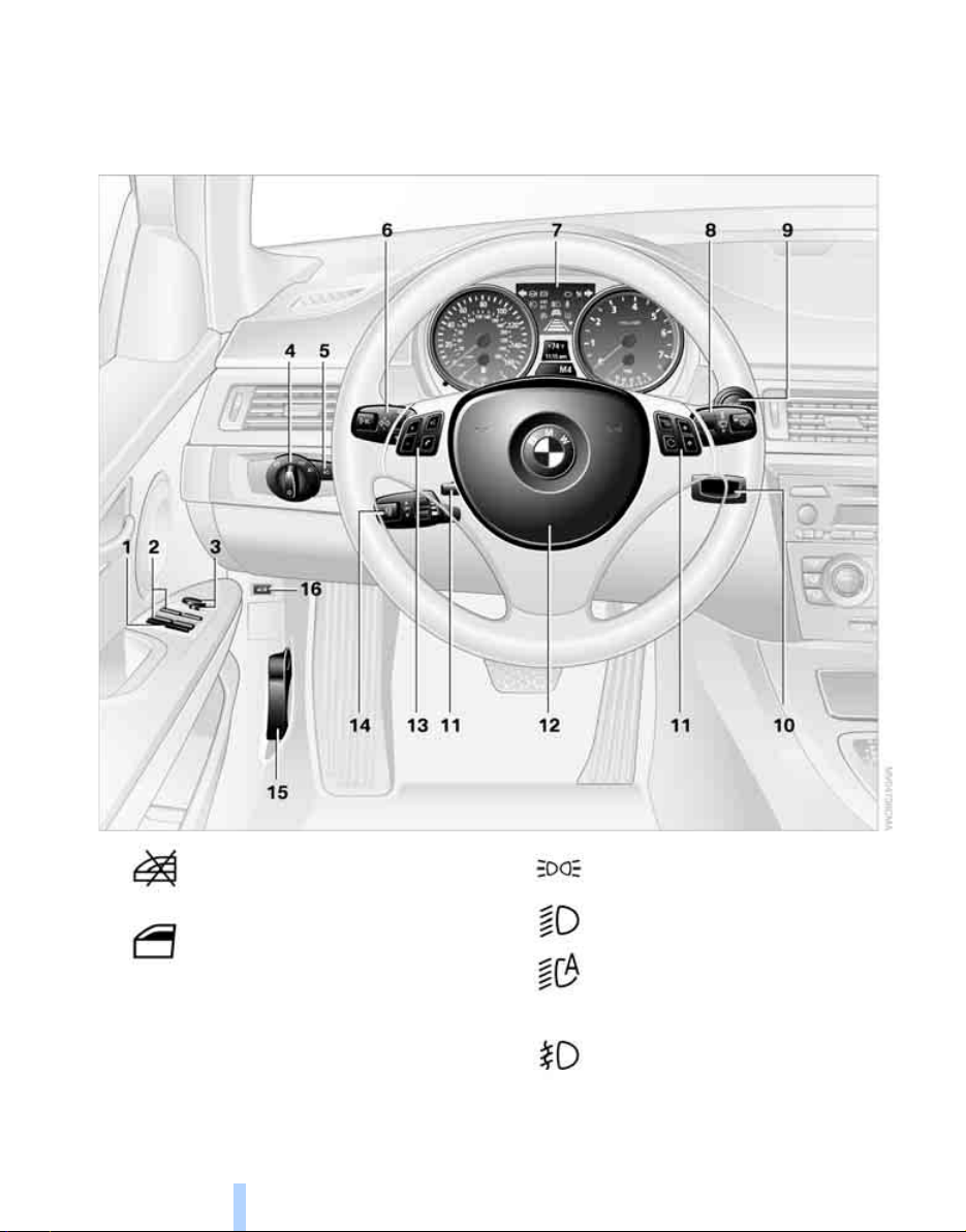
Around the steering wheel: controls and displays
Cockpit
1
2
3 Adjusting exterior mirrors, automatic curb
monitor
Safety switch for electric rear
windows 28
Opening and closing windows 27
* 37
10
4
5
Parking lamps 76
Low beams 76
Automatic headlamp control
Adaptive Head Light
Fog lamps
* 78
* 77
* 76
Page 13
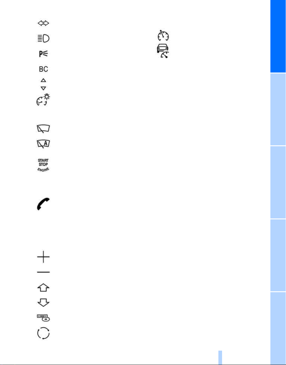
6
Online Edition for Part-No. 01 41 0 159 813 - © 09/05 BMW AG
Turn signals 48
High beams, headlamp flasher 78
12 Horn: the entire surface
13 Steering wheel adjustment 38
14
Cruise control
* 51
Roadside parking lamps
Computer 60
Settings and information about the
vehicle 61
Instrument lighting 78
7 Instrument cluster 12
8
9
10 Ignition lock 42
11 Buttons
Windshield wipers 49
Rain sensor
Switching the ignition on/off and
starting/stopping the engine 42
* 50
* on the steering wheel
Telephone
> Press: accepting and ending a
> Press longer: redialing
*:
call, starting dialing
selected phone number and
redialing if no phone number is
selected
* 78
* for a
Active cruise control
15 Releasing the hood 118
16 Opening the luggage compartment lid
* 53
At a glanceControlsDriving tipsMobilityReference
*
Volume
Changing radio station
Selecting music track
Scrolling through phone book and
lists with stored phone numbers
Next entertainment source
Recirculated-air mode 81
11
Page 14
Instrument cluster
Online Edition for Part-No. 01 41 0 159 813 - © 09/05 BMW AG
Cockpit
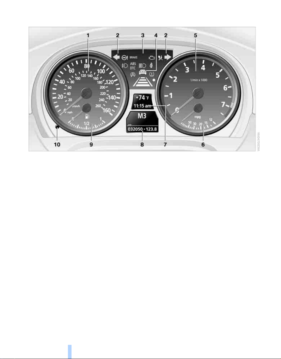
1 Speedometer
2 Indicator lamps for turn signals
3 Indicator and warning lamps 13
4 Displays for active cruise control
5 Tachometer 59
6 Energy Control 60
7 Display for
> Clock 59
> Outside temperature 59
> Indicator and warning lamps 65
* 53
8 Display for
> Position of automatic transmission
> Sequential manual gearbox SMG
> Computer 60
> Date of next scheduled service, and
remaining distance to be driven 63
> Odometer and trip odometer 59
> Initializing Flat Tire Monitor 72
> Checking engine oil level
> Settings and information 61
9 Fuel gauge 60
10 Resetting trip odometer 59
* 119
* 47
* 45
12
Page 15
Indicator and warning lamps
Online Edition for Part-No. 01 41 0 159 813 - © 09/05 BMW AG
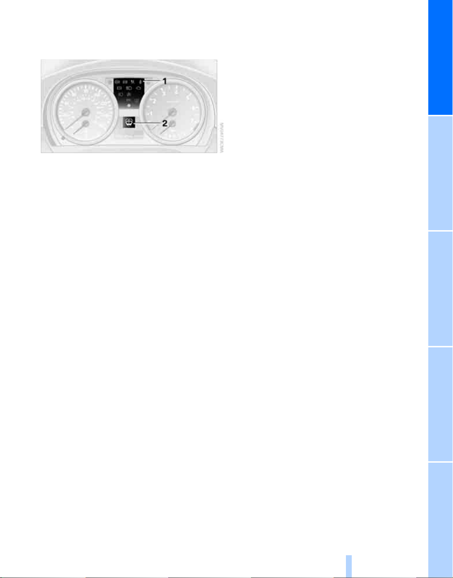
The concept
Indicator and warning lamps can light up in various combinations and colors in both the indicator area 1 and the display 2.
Some lamps are checked for proper functioning
and thus come on briefly when the engine is
started or the ignition is switched on.
What to do in case of a malfunction
A list of all indicator and warning lamps, as well
as notes on possible causes of malfunctions
and on how to respond, can be found starting
on page 136.
At a glanceControlsDriving tipsMobilityReference
13
Page 16
Around the center console: controls and displays
Online Edition for Part-No. 01 41 0 159 813 - © 09/05 BMW AG
Cockpit
14
Page 17
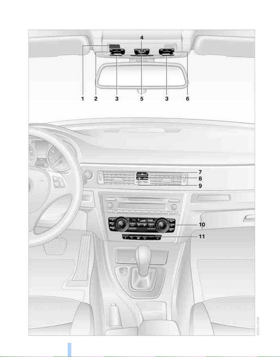
1 Microphone for voice command system*
Online Edition for Part-No. 01 41 0 159 813 - © 09/05 BMW AG
and for telephone in hands-free mode*
2 Initiating an emergency call*
3 Reading lamps 79
4 Glass sunroof, electric
5 Interior lamps 79
6 Passenger airbag status lamp
7 Hazard warning flashers
8 DTC Dynamic Traction Control 68
9 Central locking system 22
10 Air conditioner or automatic climate con-
*
trol
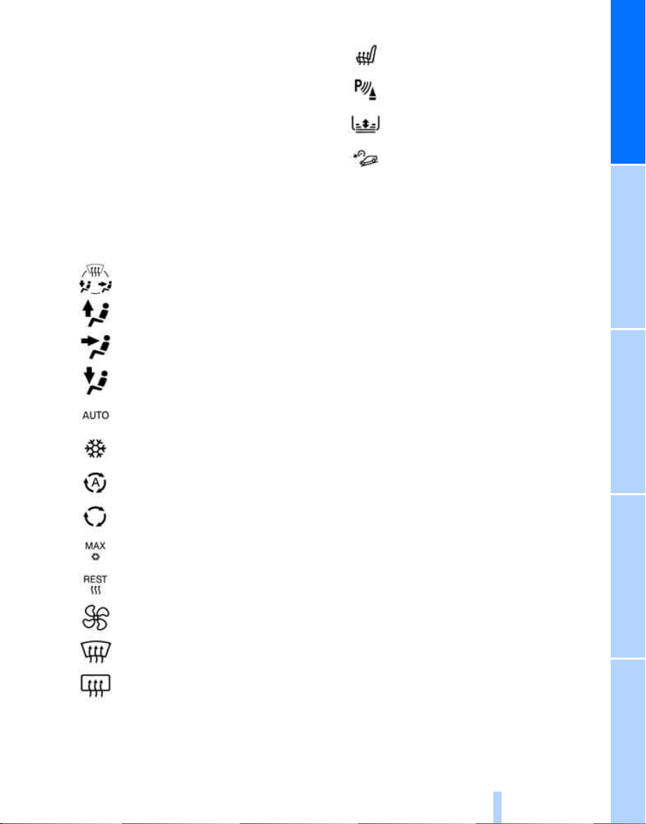
Air distribution for air
conditioner 81
Air distribution to the
windshield
Air distribution to the upper body
area
* 83
* 28
* 75
* 83
11
Heated seats
PDC Park Distance Control
Roller sun blind
Hill Descent Control HDC
* 34
* 89
* 67
* 69
At a glanceControlsDriving tipsMobilityReference
Air distribution to the footwell
Automatic air distribution and flow
* 84
rate
Cooling function 85
AUC Automatic recirculated-air
control
* 84
Recirculated-air mode 81, 84
Maximum cooling
Residual heat mode
Air flow rate 81, 84
Defrosting windows
Rear window defroster 81, 85
* 83
* 84
* 85
* 83
15
Page 18
Online Edition for Part-No. 01 41 0 159 813 - © 09/05 BMW AG
Page 19
Controls
Online Edition for Part-No. 01 41 0 159 813 - © 09/05 BMW AG
Controls
This chapter is intended to provide you with
information for complete control of your vehicle.
All features and accessories that are useful for
driving and your safety, comfort and
convenience are described here.
Page 20
Opening and closing
Online Edition for Part-No. 01 41 0 159 813 - © 09/05 BMW AG
Keys/remote controls
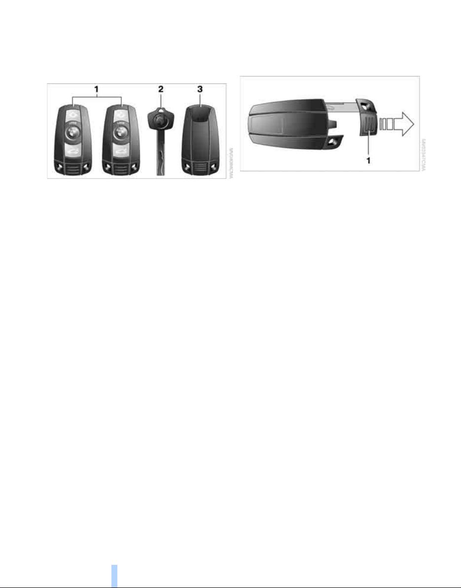
1 Remote control with integrated key
Opening and closing
2 Spare key
3 Adapter for spare key, in the glove compart-
ment
Remote control with integrated key
Each remote control contains a rechargeable
battery that is automatically recharged when it
is in the ignition lock while the car is being
driven. Use the remote control at least twice a
year in order to keep the batteries charged. In
cars equipped with convenient access
remote control contains a replaceable battery,
refer to page 27.
The settings called up and implemented when
the car is unlocked depend on which remote
control is used to unlock the car, refer to Personal Profile, page 19.
In addition, information about service requirements is stored in the remote control, refer to
Service data in the remote control, page 123.
*, the
Integrated key
Press button 1 to release the key.
The integrated key fits the following locks:
> Glove compartment, refer to page 89
> Driver's door, refer to page 22
> Luggage compartment lid, refer to page 23
New remote controls
Your BMW Center can supply new remote controls with integrated keys as additional units or
as replacements in the event of loss.
Spare key
Spare key for storage in a safe place, such as in
your wallet. This key is not intended for regular
use.
The spare key and the integrated key fit the
same locks.
Adapter for spare key
The adapter is necessary for starting the car
with the spare key or switching on radio readiness.
18
Page 21

Take the adapter out of the bracket on the
Online Edition for Part-No. 01 41 0 159 813 - © 09/05 BMW AG
inside of the glove compartment and slide the
spare key into the adapter before using it.
> Units of measure for fuel consumption, dis-
tance covered/remaining distances, and
temperature, refer to page 62
> Automatic climate control
gram, activating/deactivating cooling function and automatic recirculated-air control,
setting temperature, air flow rate and distribution, refer to page 83 ff
> Audio volume, refer to separate Owner's
Manual
> Speed-dependent volume, refer to sepa-
rate Owner's Manual
*: AUTO pro-
Personal Profile
The concept
You can set many of your BMW's functions to
suit your personal needs and preferences.
Without any action on your part, Personal Profile ensures that most of these settings are
stored for the remote control currently in use.
When you unlock the car, the remote control
used for the purpose is recognized and the settings stored for it are called up and implemented.
This means that your personal settings are
active when you return to your BMW, even if the
car was used in the meantime by someone else
with a remote control of their own and the settings were changed accordingly.
You can configure a maximum of three remote
controls for three different people. The prerequisite for this is that each person has his or her
own remote control.
Personal Profile settings
For more information on specific settings, refer
to the specified pages.
> Automatic call-up
exterior-mirror positions after unlocking,
refer to page 35
> 12h/24h mode of the clock, refer to page 62
> Date format, refer to page 62
* of the driver's-seat and
Central locking system
The concept
The central locking system is ready for operation whenever the driver's door is closed.
The system simultaneously engages and
releases the locks on the following:
> Doors
> Luggage compartment lid
> Fuel filler door
Operating from outside
> Via the remote control
> Via the door lock
> In cars with convenient access
handles on the driver's and front passenger's doors
The anti-theft system is also operated at the
same time. It prevents the doors from being
unlocked using the lock buttons or door handles. The interior lamp and the courtesy lamps
are also switched on or off with the remote control. The alarm system
armed.
For further details of the alarm system,
page 24.
* is also armed or dis-
Operating from inside
By means of the button for central locking, refer
to page 22.
*, via the
refer to
*
19
Reference At a glanceControlsDriving tipsMobility
Page 22
In the event of a sufficiently severe accident, the
Online Edition for Part-No. 01 41 0 159 813 - © 09/05 BMW AG
central locking system unlocks automatically. In
addition, the hazard warning flashers and interior lamps come on.
Opening and closing: from outside
Using the remote control
Persons or animals in a parked vehicle
could lock the doors from the inside. You
should therefore take the remote control with
you so that the car can be opened from the outside.<
Opening and closing
Unlocking
Press the button.
The interior lamp and the doors' courtesy
* come on. Exterior mirrors that were
lamps
folded in are automatically folded back out
You can also set the way in which the car is
unlocked. The setting is stored for the remote
control currently in use.
Operating principle, refer to page 61.
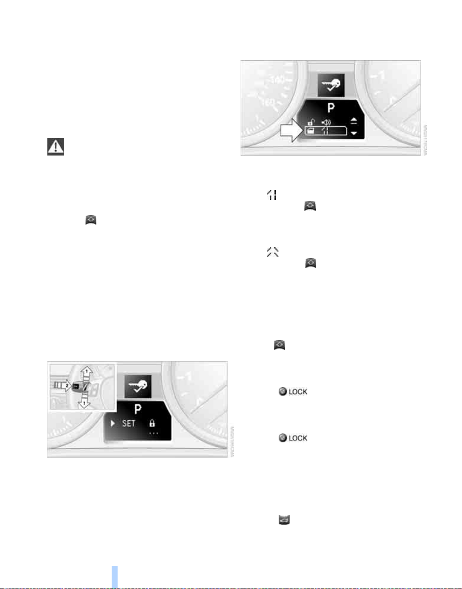
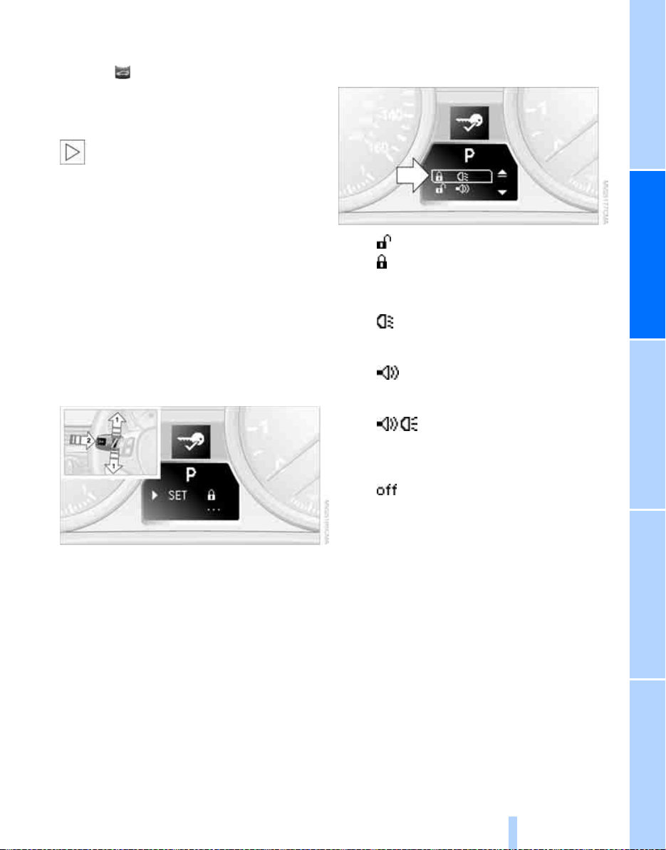
1. Lightly push button 1 in the turn indicator
stalk up or down repeatedly until the symbol
appears in the display accompanied by the
word "SET".
3. Lightly push button 1 in the turn indicator
stalk down repeatedly until the symbol
appears in the display.
4. Press button 2.
5. Use button 1 to select:
>
Press the button once to unlock only
the driver's door and the fuel filler door.
Press the button twice to unlock the
entire vehicle.
*.
>
Press the button once to unlock the
entire vehicle.
6. Press button 2.
The setting is stored for the remote control
currently in use.
Convenience opening
Hold the button down. The electric windows
and the glass sunroof* are opened.
2. Press button 2.
20
Locking
Press the button.
Switching on interior lamps
While the car is locked:
Press the button.
You can also use this function to locate your
vehicle in parking garages etc.
Panic mode*
You can also trigger the alarm system if you find
yourself in a dangerous situation:
Press the button for at least three seconds.
To switch off the alarm: press any button.
Page 23
Unlocking the luggage compartment
Online Edition for Part-No. 01 41 0 159 813 - © 09/05 BMW AG
lid
Press the button for a longer period.
The luggage compartment lid opens a short
distance, regardless of whether it was locked or
unlocked.
In order to avoid damage, make sure there
is sufficient clearance in all directions
before opening the luggage compartment lid.
A previously locked luggage compartment lid is
locked again after closing.
Before and after each trip, check that the luggage compartment lid has not been inadvertently unlocked.<
Setting confirmation signals
You can program the vehicle to confirm when it
has been locked or unlocked.
1. Lightly push button 1 in the turn indicator
stalk up or down repeatedly until the symbol
appears in the display accompanied by the
word "SET".
2. Press button 2.
3. Lightly push button 1 in the turn indicator
stalk down repeatedly until the desired
symbol appears in the display.
> Confirmation signal during unlocking
> Confirmation signal during locking
4. Press button 2.
5. Use button 1 to select:
>
The hazard warning flashers light up
during unlocking/locking.
>
An acoustic signal sounds during
unlocking/locking.
>
The hazard warning flashers light up and
an acoustic signal sounds during
unlocking/locking.
>
The function is deactivated.
6. Press button 2.
The setting is stored.
Malfunctions
The remote control may malfunction due to
local radio waves. If this occurs, unlock and lock
the car at the door lock with the integrated key.
If the car can no longer be locked with a remote
control, the battery in the remote control is discharged. Use this remote control during an
extended drive; this will recharge the battery,
refer to page 18.
For US owners only
The transmitter and receiver units comply with
part 15 of the FCC/Federal Communications
21
Reference At a glanceControlsDriving tipsMobility
Page 24
Commission regulations. Operation is gov-
Online Edition for Part-No. 01 41 0 159 813 - © 09/05 BMW AG
erned by the following:
FCC ID:
LX8766S
LX8766E
LX8CAS
Compliance statement:
This device complies with part 15 of the FCC
Rules. Operation is subject to the following two
conditions:
> This device must not cause harmful inter-
ference, and
> This device must accept any interference
received, including interference that may
Opening and closing
cause undesired operation.
Any unauthorized modifications or
changes to these devices could void the
user's authority to operate this equipment.<
Using the door lock
integrated key or the spare key to the corresponding limit positions in the door lock.
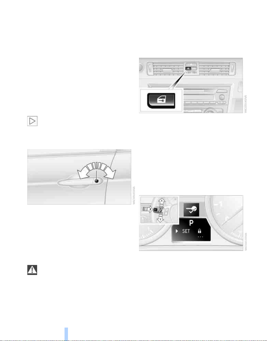
Opening and closing: from inside
This button serves to unlock or lock doors and
the luggage compartment lid, but does not activate the anti-theft system. The fuel filler door
remains unlocked.
You can also set the situations in which the car
locks:
Operating principle, refer to page 61.
1. Lightly push button 1 in the turn indicator
stalk up or down repeatedly until the symbol
appears in the display accompanied by the
word "SET".
You can set the way in which the car is
unlocked, refer to page 20.
Convenient operation
You can also operate the windows and glass
sunroof via the door lock
Hold the key in the position for unlocking or
locking.
Watch during the closing process to be
sure that no one is injured. Releasing the
key stops the operation.<
.
Manual operation
In the event of an electrical malfunction, you can
lock and unlock the driver's door by turning the
22
2. Press button 2.
Page 25
3. Lightly push button 1 in the turn indicator
Online Edition for Part-No. 01 41 0 159 813 - © 09/05 BMW AG
stalk down repeatedly until the symbol
appears in the display.
4. Press button 2.
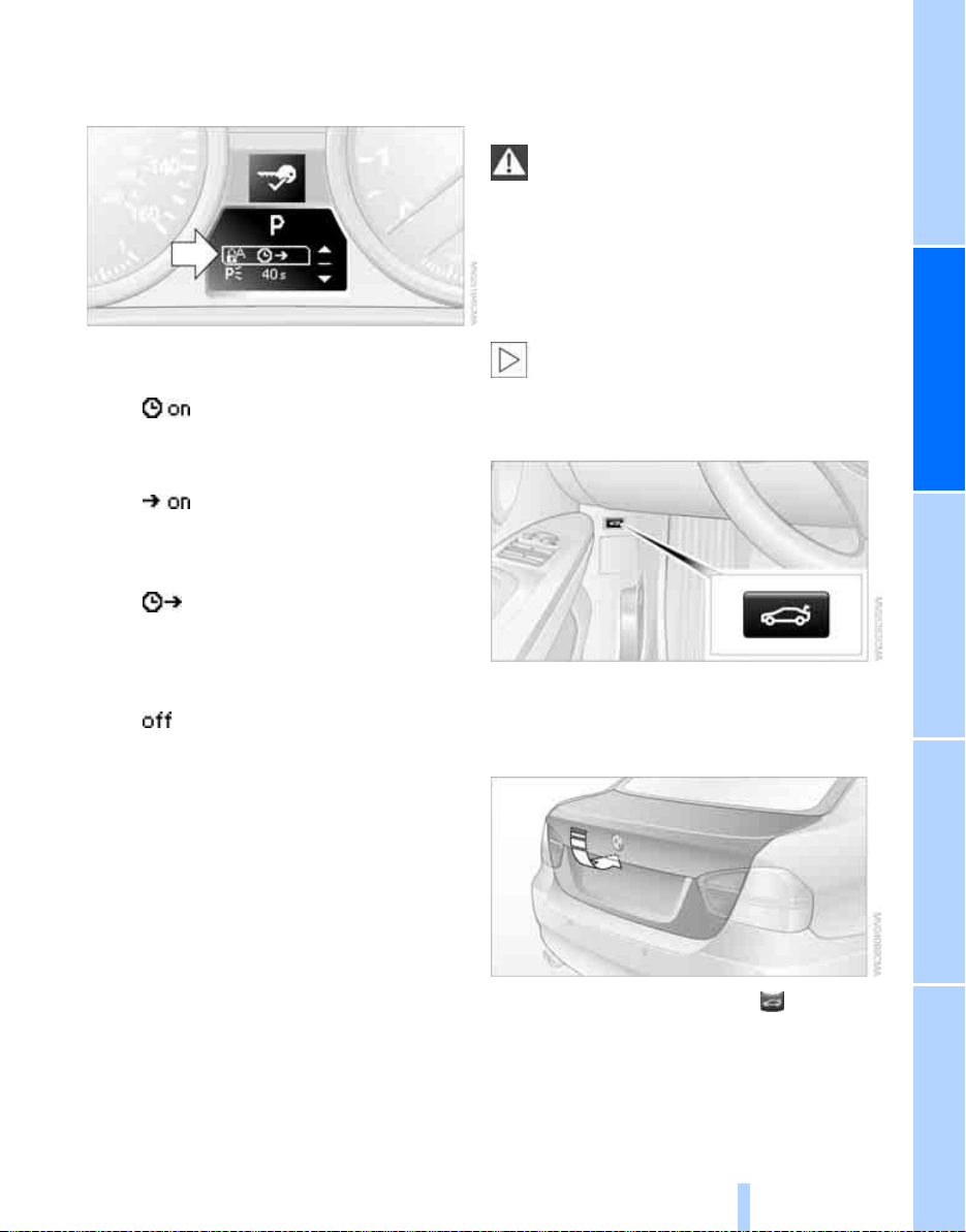
5. Use button 1 to select:
>
The central locking system automatically locks the vehicle after some time if
no door has been opened.
>
The central locking system automatically locks the vehicle as soon as you
drive off.
>
The central locking system automatically locks the vehicle after some time if
no door has been opened, or as soon as
you drive off.
>
The central locking system remains
unlocked.
6. Press button 2.
The setting is stored.
> press down the safety lock button of a door.
To prevent you from being locked out, the
open driver's door cannot be locked using
the lock button.
Persons or animals in a parked vehicle
could lock the doors from the inside. You
should therefore take the remote control with
you so that the car can be opened from the outside.<
Luggage compartment lid
In order to avoid damage, make sure there
is sufficient clearance in all directions
before opening the luggage compartment lid.<
Opening from inside
Press the button: the luggage compartment lid
opens unless it has been locked.
Opening from outside
Unlocking and opening doors
> Either unlock the doors together using the
button for the central locking system and
then pull the door handle above the armrest
or
> pull on the door handle of each door twice:
the first time unlocks the door, the second
time opens it.
Locking
> Use the central locking button to lock all of
the doors simultaneously, or
Press the button, see arrow, or the button on
the remote control for a longer period. The luggage compartment lid will open slightly. It can
now be swung upwards.
23
Reference At a glanceControlsDriving tipsMobility
Page 26
The integrated key of the remote control and
Online Edition for Part-No. 01 41 0 159 813 - © 09/05 BMW AG
the spare key, refer to page 18, fit the luggage
compartment lid lock.
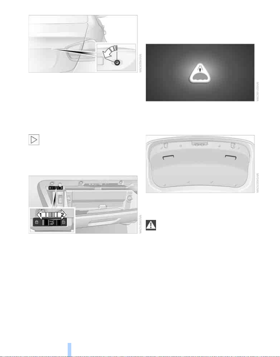
Unlocking separately
Push the switch in the direction of arrow 2.
Emergency release
Opening manually
Turn the integrated key of the remote control or
Opening and closing
the spare key all the way to the left: the luggage
compartment lid opens.
If you unlock and open the luggage compartment lid with the key while the alarm
system is armed, the alarm will be triggered.
Switching off an alarm, refer to page 25.<
Locking or unlocking separately
The switch is located in the glove compartment.
1 Locking the luggage compartment lid
2 Unlocking the luggage compartment lid
Locking separately
Push the switch in the direction of arrow 1.
The luggage compartment lid is locked and
cannot be unlocked using the central locking
system.
If you give the remote control without the integrated key to someone else while the glove
compartment is locked, the luggage compartment lid cannot be opened. This is an advantage when valet parking, for example.
Pull the lever in the luggage compartment. The
luggage compartment lid is unlocked.
Closing
The handle recesses on the interior trim of the
luggage compartment lid make it easier to pull
down.
Make sure that the closing path of the
luggage compartment lid is clear, other-
wise injuries may result.<
Alarm system*
The concept
The vehicle alarm system responds:
> When a door, the hood or the luggage com-
partment lid is opened
> To movements inside the vehicle: Interior
motion sensor, refer to the information further below
> When the car's inclination changes, for
instance if an attempt is made to jack it up
24
Page 27
and steal the wheels or to raise it prior to
Online Edition for Part-No. 01 41 0 159 813 - © 09/05 BMW AG
towing away
> When there is an interruption in the power
supply from the battery
The alarm system signals unauthorized entry
attempts for a short time by means of:
> An acoustic alarm
> Switching on the hazard warning flashers
> Flashing the high beams
Arming and disarming
When you lock or unlock the vehicle, either with
the remote control or at the door lock, the alarm
system is armed or disarmed at the same time.
Even when the alarm system is armed, you can
open the luggage compartment lid by means of
the button on the remote control, refer to
page 21. When you subsequently close the luggage compartment lid, it is again locked and
monitored.
lamp flashes continuously after approx. 10
seconds. However, the interior motion sensor is not activated.
> The indicator lamp goes out after unlocking:
your vehicle has not been disturbed while
you were away.
> If the indicator lamp flashes after unlocking
until the remote control is inserted in the
ignition, but for no longer than approx.
5 minutes: your vehicle has been disturbed
while you were away.
Tilt alarm sensor
The tilt of the vehicle is monitored. The alarm
system reacts, e.g. to attempts to steal a wheel
or tow the vehicle.
Interior motion sensor
In order for the interior motion sensor to function properly, the windows and glass sunroof
must be completely closed.
Switching off an alarm
> Unlock the car with the remote control, refer
to page 20, or
> insert the remote control all the way into the
ignition lock.
Indicator lamp displays
> The indicator lamp under the inside rear-
view mirror flashes continuously: the system is armed.
> The indicator lamp flashes after locking:
doors, hood or luggage compartment lid are
not properly closed. Even if you do not close
the alerted area, the system begins to monitor the remaining areas, and the indicator
Avoiding unintentional alarms
The tilt alarm sensor and interior motion sensor
may be switched off at the same time. This prevents unintentional alarms, e.g. in the following
situations:
> In duplex garages
> When transporting on car-carrying trains
> When animals are to remain in the vehicle
Switching off tilt alarm sensor and
interior motion sensor
Press the button on the remote control
twice in a row.
The indicator lamp comes on for approx. two
seconds, then begins to flash steadily. The tilt
alarm sensor and the interior motion sensor are
switched off until the next time the vehicle is
unlocked and subsequently locked again.
Convenient access*
Convenient access enables you to enter your
vehicle without needing to hold the remote con-
25
Reference At a glanceControlsDriving tipsMobility
Page 28
trol in your hand. All you need to do is wear the
Online Edition for Part-No. 01 41 0 159 813 - © 09/05 BMW AG
remote control close to your body, e.g. in your
jacket pocket. The vehicle automatically
detects the corresponding remote control
within the immediate vicinity or in the passenger compartment.
Convenient access supports the following
functions:
> Unlocking/locking the vehicle
> Unlocking the luggage compartment lid
separately
> Engine starting
> Convenient closure
Functional requirement
Opening and closing
> The vehicle or the luggage compartment lid
can only be locked when the vehicle detects
that the remote control currently in use is
outside of the vehicle.
> The vehicle cannot be locked or unlocked
again until after approx. 2 seconds.
> The engine can only be started when the
vehicle detects that the remote control currently in use is inside the vehicle.
Special features in comparison to
conventional remote controls
In general, there is no difference between using
convenient access or pressing the buttons on
the remote control to carry out the functions
mentioned above. You should therefore first
familiarize yourself with the instructions on
opening and closing starting on page 18.
Special features regarding the use of convenient access are described below.
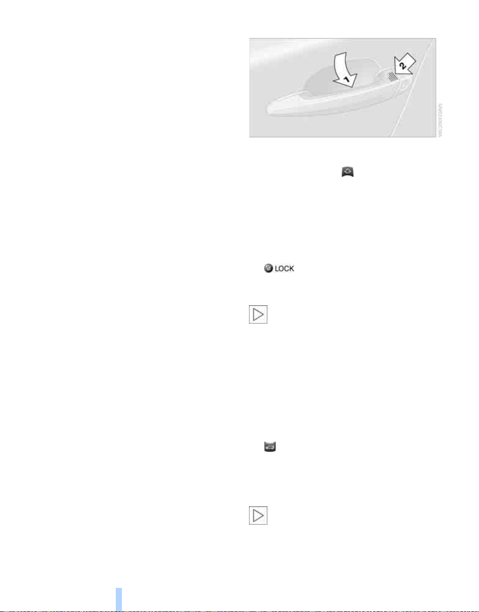
Unlocking
Grasp the handle on the driver's or front passenger's door completely, arrow 1. This corresponds to pressing the button.
If a remote control is detected inside the car
after the vehicle is unlocked, the electric steering wheel lock is released, refer to page 42.
Locking
Touch the surface, arrow 2, with your finger for
approx. 1 s econd. This corresponds to pressing
the button.
For convenient closure, keep your finger on the
surface, arrow 2.
If the vehicle detects that a remote con-
trol has been accidentally left inside the
locked vehicle's luggage compartment after the
luggage compartment lid is closed, the luggage
compartment lid will reopen slightly. The hazard
warning flashers flash and an acoustic signal
sounds.<
*
Unlocking just the luggage
compartment lid
Press the button on the outside of the luggage
compartment lid. This corresponds to pressing
the button.
Switching on radio readiness
Radio readiness is switched on by pressing the
start/stop button, refer to page 42.
Do not depress the brake or the clutch,
otherwise the engine will start immediately.<
26
Page 29
Starting the engine
Online Edition for Part-No. 01 41 0 159 813 - © 09/05 BMW AG
You can start the engine or switch on the ignition when a remote control is inside the vehicle.
It is not necessary to insert a remote control into
the ignition switch, refer to page 42.
Switching off the engine in vehicles
with automatic transmission
The engine can only be switched off when the
selector lever is in position P, refer to page 44.
To switch the engine off when the selector lever
is in position N, the remote control must be in
the ignition switch.
Before driving a vehicle with automatic
transmission into a car wash
1. Insert remote control into ignition switch.
2. Depress the brake.
3. Move the selector lever to position N.
4. Switch off the engine.
The vehicle can roll.
Malfunction
Convenient access may malfunction due to
local radio waves. If this happens, open or close
the vehicle via the buttons on the remote control or using the integrated key. To start the
engine afterward, insert the remote control into
the ignition switch.
Warning lamps
The warning lamp in the instrument
cluster lights up when you attempt to
start the engine: the engine cannot
be started. The remote control is not inside the
vehicle or is malfunctioning. Take the remote
control with you inside the vehicle or have it
checked. If necessary, insert another remote
control into the ignition switch.
The warning lamp in the instrument
cluster lights up while the engine is
running: the remote control is no
longer inside the vehicle. After the engine is
switched off, the engine can only be restarted
within approx. 10 seconds.
The indicator lamp in the instrument
cluster comes on: replace the battery
in the remote control.
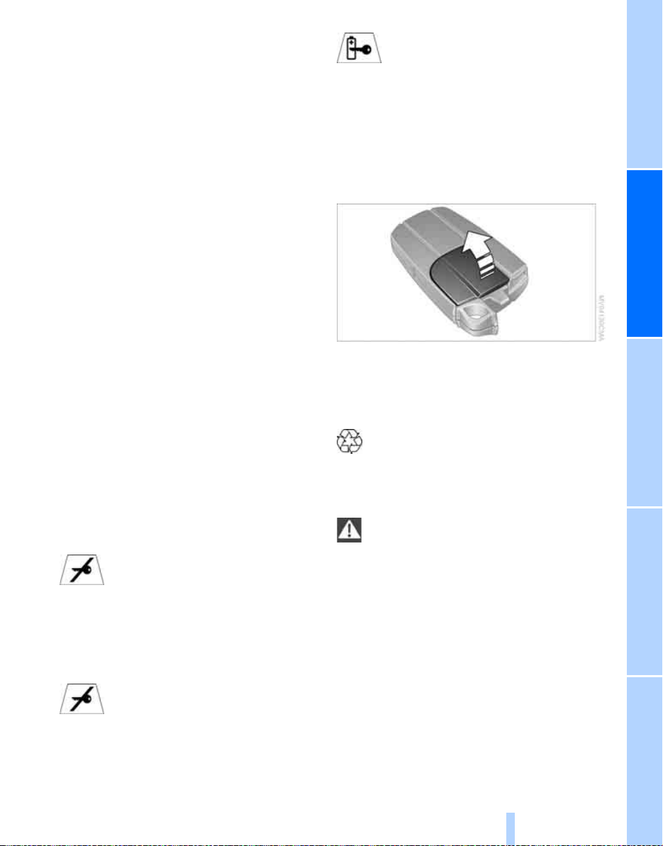
Replacing the battery
The remote control for convenient access contains a battery that will need to be replaced from
time to time.
1. Take the integrated key out of the remote
control, refer to page 18.
2. Remove the cover.
3. Insert the new battery with the plus side fac-
ing up.
4. Press the cover on to close.
Take the old battery to a battery collection point or to your BMW Center.<
Windows
To prevent injuries, exercise care when
closing the windows and keep them in
your field of vision until they are shut.
Take the remote control with you when you
leave the car, otherwise children could operate
the electric windows and possibly injure themselves.<
27
Reference At a glanceControlsDriving tipsMobility
Page 30
Opening, closing
Online Edition for Part-No. 01 41 0 159 813 - © 09/05 BMW AG
> Press the switch to the resistance point.
The window continues to open as long as
you keep the switch pressed.
> Press the switch beyond the resistance
Opening and closing
point.
The window opens automatically. Press the
switch again to stop the opening movement.
You can close the windows in the same manner
by pulling the switch.
There are separate switches in the rear seat
armrests.
After switching off the ignition
When the remote control is removed or the ignition is switched off, you can still operate the
windows for approx. 1 minute as long as no
door is opened.
For information on convenient operation via the
remote control or the door lock, refer to page 20
or 22. For information on closing with convenient access, refer to Locking on page 20.
Take the remote control with you when
you leave the car, otherwise children
could operate the electric windows and possibly injure themselves.<
Anti-trapping mechanism
If the closing force exceeds a specific value as
an electric window closes, the closing action is
interrupted immediately and the window
reopens slightly.
Despite the anti-trapping mechanism
check and clear the window's travel path
prior to closing it, otherwise the safety system
might fail to detect certain kinds of obstruc-
tions, such as thin objects, and the window
would continue closing.
Pulling the switch beyond the resistance point
and holding it limits the response of the antitrapping mechanism. In this case, if the closing
force exceeds a defined threshold, the window
will only open a few fractions of an inch/a few
millimeters.
If the switch is pulled past the resistance point
again within approx. 4 seconds, the anti-trapping mechanism will be deactivated.<
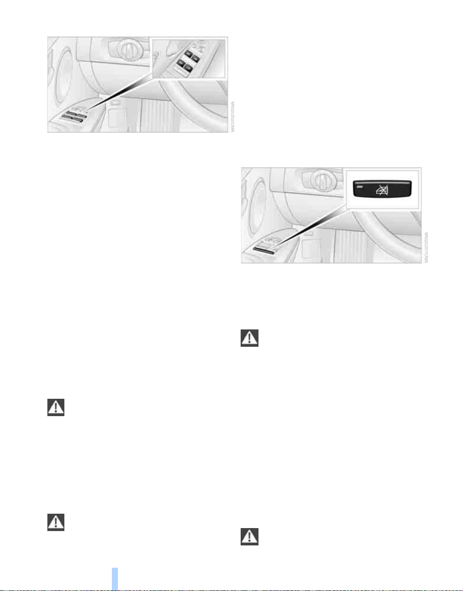
Safety switch
With the safety switch, you can prevent the rear
windows from being opened or closed via the
switches in the rear passenger area, by children, for example. When the safety function is
switched on, the LED comes on.
Always press the safety switch when children ride in the rear, otherwise
unchecked closing of the windows could lead to
injuries.<
Accessories in a window area
If you install accessories within the power window movement range, e.g. a clip-on antenna for
your mobile phone, the system must be initialized to teach it the new conditions. BMW recommends having this work done by your BMW
Center.
Glass sunroof*, electric
The glass sunroof is operational when the ignition is switched on, refer to page 42.
To prevent injuries, exercise care when
closing the glass sunroof and keep it in
28
Page 31

your field of vision until it is shut.
Online Edition for Part-No. 01 41 0 159 813 - © 09/05 BMW AG
Take the remote control with you when you
leave the car, otherwise children could operate
the sunroof and possibly injure themselves.<
Raising
Press the switch.
> The closed glass sunroof is raised and the
sliding visor is opened slightly.
> When the glass sunroof is open, it automat-
ically travels into the raised position. The
sliding visor remains completely open.
Do not close the sliding visor forcibly with
the roof in the raised position, otherwise
this could damage the mechanism.<
Opening, closing
> Press the switch backwards to the resis-
tance point.
The glass sunroof and the sliding visor open
together as long as you hold the switch in
this position.
> Press the switch backwards past the resis-
tance point.
The glass sunroof and the sliding visor open
automatically. Briefly press the switch again
to stop the opening movement.
You can close the glass sunroof in a similar
manner by pressing the switch forwards. The
sliding visor remains open and can be closed by
hand.
For information on convenient operation via the
remote control or door lock, refer to page 20
or 22.
Anti-trapping mechanism
If the glass sunroof encounters an obstruction
during closing from approximately the middle of
the opening in the roof, or during closing from
the raised position, the closing movement is
interrupted and the glass sunroof is opened
again slightly.
Despite the anti-trapping mechanism
check and clear the sunroof's travel path
prior to closing it, otherwise the safety system
might fail to detect certain kinds of obstructions, such as very thin objects, and the sunroof
would continue closing.
Pressing the switch beyond the resistance
point and holding it there deactivates the antitrapping mechanism.<
Following interruptions in electrical
power supply
After a power failure, there is a possibility that
the sunroof can only be raised. The system
must be initialized. BMW recommends having
this work done by your BMW Center.
Closing manually
In the event of an electrical malfunction, you can
move the glass sunroof manually:
1. Unclip the front of the cover of the interior
lamps using the screwdriver from the
onboard tool kit, refer to page 125.
29
Reference At a glanceControlsDriving tipsMobility
Page 32

2. Insert the screwdriver into the openings on
Online Edition for Part-No. 01 41 0 159 813 - © 09/05 BMW AG
each side to press the clips.
3. Remove the control unit.
4. Unplug the motor. Considerably less effort
will be required for manual operation.
Opening and closing
5. Insert the Allen wrench supplied with the
onboard tool kit, refer to page 125, into the
opening provided. Move the glass sunroof
in the desired direction.
6. Reinstall the control unit and reattach the
lamp cover.
30
Page 33

Adjustments
Online Edition for Part-No. 01 41 0 159 813 - © 09/05 BMW AG
Sitting safely
The ideal sitting position can make a vital contribution to relaxed, fatigue-free driving. In conjunction with the safety belts, the head
restraints and the airbags, the seated position
has a major influence on your safety in the event
of an accident. To ensure that the safety systems operate with optimal efficiency, we
strongly urge you to observe the instructions
contained in the following section.
For additional information on transporting children safely, refer to page 39.
Airbags
Always maintain an adequate distance
between yourself and the airbags. Always
grip the steering wheel on the rim, with your
hands in the 3 o'clock and 9 o'clock positions,
to minimize the risk of injury to the hands or
arms in the event of the airbag being triggered
off.
No one and nothing is to come between the airbags and the seat occupant.
Do not use the cover of the front airbag on the
front passenger side as a storage area. Make
sure that the front passenger is sitting correctly,
e.g. not resting feet or legs on the instrument
panel, otherwise leg injuries can occur if the
front airbag is triggered.
Make sure that passengers do not lean their
heads against the side or head airbags, otherwise serious injuries could result if the side airbags suddenly deployed.<
Even if you follow all the instructions, injuries
resulting from contact with airbags cannot be
fully excluded, depending on the circumstances. The ignition and inflation noise may
provoke a mild hearing loss in extremely sensitive individuals. This effect is usually only temporary.
For airbag locations and additional information
on airbags, refer to page 74.
Head restraint
A correctly adjusted head restraint reduces the
risk of neck injury in the event of an accident.
Adjust the head restraint in such a way
that its center is at approx. ear level. Oth-
erwise, there is an increased risk of injury in the
event of an accident.<
Head restraints, refer to page 33.
Safety belt
Before every drive, make sure that all occupants
wear their safety belts. Airbags complement the
safety belt as an additional safety device, but
they do not represent a substitute.
Never allow more than one person to
wear a single safety belt. Never allow
infants or small children to ride in a passenger's
lap.
Expectant mothers should also wear the safety
belt, making sure that the strap in the pelvic
area is well down on the hips and does not press
against the abdominal region of the body.
Do not route the belt across your neck, or run it
across sharp edges. Be sure that the belt does
not become caught or jammed. The safety belt
should not be twisted and must be positioned
firmly over the pelvis and shoulder, as close to
the body as possible. It should not pass over
hard or fragile objects, otherwise the belt in the
pelvic area could slide over the hips in the event
of a head-on collision and injure the lower abdomen. Avoid wearing bulky clothing and regularly
pull the belt in the upper-body area taut, otherwise its restraining effect could be impaired.<
Safety belts, refer to page 36.
Seats
Note before adjusting
Never attempt to adjust your seat while
the vehicle is moving. The seat could
respond with unexpected movement, and the
31
Reference At a glanceControlsDriving tipsMobility
Page 34

ensuing loss of vehicle control could lead to an
Online Edition for Part-No. 01 41 0 159 813 - © 09/05 BMW AG
accident.
On the front passenger seat as well, do not
incline the backrest too far to the rear while the
vehicle is being driven, otherwise there is a danger in the event of an accident of sliding under
the safety belt, eliminating the protection normally provided by the belt.<
Comply with the instructions on head restraint
height on page 33, and on damaged safety
Adjustments
belts on page 36.
Seat adjustment
Observe the adjustment instructions on
page 31 to ensure the best possible per-
sonal protection.<
Longitudinal direction
Pull lever 1 and slide the seat to the desired
position.
After releasing the lever, move the seat gently
forward or back to make sure it engages properly.
Height
Pull lever 2 and apply your weight to the seat or
lift it off, as necessary.
Backrest
Pull lever 3 and apply your weight to the back-
rest or lift it off, as necessary.
Lumbar support*
You can also adjust the contour of the backrest
to obtain additional support in the lumbar
region.
The upper hips and spinal column receive supplementary support to help you maintain a
relaxed, upright sitting position.
> Increase or decrease curvature: push
switch forward or back.
> Shift curvature up or down: push switch up
or down.
Electric seat adjustment*
Comply with the adjusting instructions
mentioned above to ensure the best pos-
sible personal protection.<
32
Page 35

1 Longitudinal direction
Online Edition for Part-No. 01 41 0 159 813 - © 09/05 BMW AG
2 Height
3 Angle
4 Backrest
The head restraints are adjusted manually, refer
to Head restraints below.
Sports seat*
On this seat, you can manually adjust the thigh
support, the tilt angle and the width of the backrest.
Angle
Pull the lever and apply your weight to the seat
or lift it off, as necessary.
Backrest width
You can change the width of the backrest to suit
your individual preferences by adjusting the lateral-support pads.
Push switch forward or back.
Backrest width decreases or increases accordingly.
Thigh support
Pull the lever and move the thigh support forward or back.
Head restraints
A correctly adjusted head restraint reduces the
risk of neck injury in the event of an accident.
Adjust the head restraint in such a way
that its center is at approx. ear level. Otherwise, there is an increased risk of injury in the
event of an accident.<
33
Reference At a glanceControlsDriving tipsMobility
Page 36

Front seats
Online Edition for Part-No. 01 41 0 159 813 - © 09/05 BMW AG
Height adjustment
Adjustments
> To raise: pull up.
> To lower: press the button, arrow 1, and
slide the head restraint down.
Removing
1. Pull up all the way.
2. Press the button, arrow 1, and pull the head
restraint all the way out.
Rear seats
Height adjustment
seat backrest slightly forward before pulling
out a head restraint.
Folding the center head restraint down
and up
Folding down:
Press the button, arrow 1.
Folding up:
Pull the head restraint.
Depending on the equipment version, it may be
possible to fold the outer rear head restraints
down and up as well.
Note that it is an offense to drive with the
rear seats occupied and the rear head
restraints folded down. Fold up the head
restraints before allowing passengers to
occupy the rear seats.<
> To raise: pull up.
> To lower: press the button, arrow 1, and
slide the head restraint down.
The center head restraint is not height-adjustable.
Removing
1. Pull up all the way.
2. Press the button, arrow 1, and pull the head
restraint all the way out.
With through-loading system: Fold the rear-
34
Heated seats*
Press once for each temperature level.
Three lamps indicate the highest temperature.
To switch off:
Press button longer.
If you continue driving within the next 15 minutes, the seat heating is automatically activated
at the previously set temperature.
Page 37

Seat and mirror memory*
Online Edition for Part-No. 01 41 0 159 813 - © 09/05 BMW AG
You can store and call up two different combinations of driver's-seat and exterior-mirror
positions.
Settings for the seat back width and lumbar
support are not stored in memory.
Storing
1. Switch on radio readiness or the ignition,
refer to page 42.
2. Adjust the seat and exterior mirrors to the
desired positions.
3. Press the button.
The LED in the button lights up.
4. Press the desired memory key 1 or 2.
The LED goes out.
The driver's seat and exterior mirror positions are stored for the remote control currently in use.
Activating/deactivating automatic callup
Operating principle, refer to page 61.
1. Lightly push button 1 in the turn indicator
stalk up or down repeatedly until the symbol
appears in the display accompanied by the
word "SET".
2. Press button 2.
3. Lightly push button 1 in the turn indicator
stalk down repeatedly until the symbol
appears in the display.
Automatic call-up
You can select at what occasion the stored
positions of the driver's seat and exterior mirrors are to be called up.
> Call-up when the vehicle is unlocked
> Call-up when the driver's door is opened.
When this Personal Profile function is
used, first ensure that the footwell behind
the driver's seat is free of obstacles. Failure to
do so could cause injury to persons or damage
to objects as a result of a rearward movement of
the seat.<
The adjusting procedure is immediately halted
when you press a seat adjustment switch or one
of the MEMORY buttons.
4. Press button 2.
5. Use button 1 to select:
>
Call-up when the vehicle is unlocked.
>
Call-up when the driver's door is
opened.
>
Switch off automatic function.
6. Press button 2.
The setting is stored.
35
Reference At a glanceControlsDriving tipsMobility
Page 38

Manual call-up
Online Edition for Part-No. 01 41 0 159 813 - © 09/05 BMW AG
Do not call up memory while you are driving, otherwise unexpected seat move-
ment could result in an accident.<
Convenience mode
1. Unlock and open the driver's door or switch
on radio readiness, refer to page 42.
2. Briefly press the desired memory button 1
Adjustments
or 2.
The adjusting procedure is immediately halted
when you touch a seat adjustment switch or
one of the MEMORY buttons.
Safety feature
1. Close the driver's door and switch the igni-
tion on or off, refer to page 42.
2. Press the desired memory button 1 or 2
and maintain pressure until the adjustment
process has been completed.
If the button was pressed accidentally:
press the button again; the LED goes out.
Safety belts
Observe the adjustment instructions on
page 31 to ensure the best possible per-
sonal protection.<
Before every drive, make sure that all occupants
wear their safety belts. Airbags complement the
safety belt as an additional safety device, but
they do not represent a substitute.
On the rear seats, the center belt buckle marked
with the letters CENTER is solely intended for
the center passenger.
Closing
Make sure you hear the latch plate engage in
the belt buckle.
The upper belt anchor is suitable for adults of
any stature as long as the seat is adjusted properly, refer to page 31.
Opening
1. Grasp the belt firmly.
2. Press the red button in the buckle.
3. Guide the belt into its reel.
'Fasten safety belts' reminder for front
seats
The indicator lamp comes on and an
acoustic signal sounds. Check
whether the safety belt has been fastened correctly.
The 'Fasten safety belts' reminder is issued as
long as the driver's safety belt has not been fastened. The 'Fasten safety belts' reminder is also
activated at road speeds above approx. 5 mph
or 8 km/h if the front passenger's safety belt is
not fastened, if heavy objects are placed on the
front passenger seat, or if driver or front passenger unfasten their safety belts.
Damage to safety belts
If the safety belts are damaged or
stressed in an accident: have the belt system, including any belt tensioners, replaced and
the belt anchors checked. Have this work done
only by your BMW Center or at a workshop that
works according to BMW repair procedures
with correspondingly trained personnel. Other-
36
Page 39

wise, it is not guaranteed that the safety devices
Online Edition for Part-No. 01 41 0 159 813 - © 09/05 BMW AG
will function properly.<
Mirrors
Exterior mirrors
The front passenger's mirror is more convex
than the driver's mirror. The objects seen in the
mirror are closer than they appear. Do not
gauge your distance from traffic behind you on
the basis of what you see in the mirror; otherwise there is an increased risk of an accident.<
1 Adjustments
2 Switching to the other mirror or automatic
curb monitor
3 Folding mirrors in and out*
The positions of the exterior mirrors are stored
for the remote control currently used
Personal Profile, page 19.
*
*, refer to
Passenger-side mirror tilt function –
automatic curb monitor*
Activating
1. Push the switch to the position for the
driver's-side mirror, arrow 1.
2. Engage reverse gear or move the selector
lever to position R.
The glass of the mirror on the passenger
side tilts slightly down. This allows the
driver to see the area immediately adjacent
to the vehicle, such as a curb, when parking,
etc.
Deactivating
Push the switch to the position for the passenger-side mirror, arrow 2.
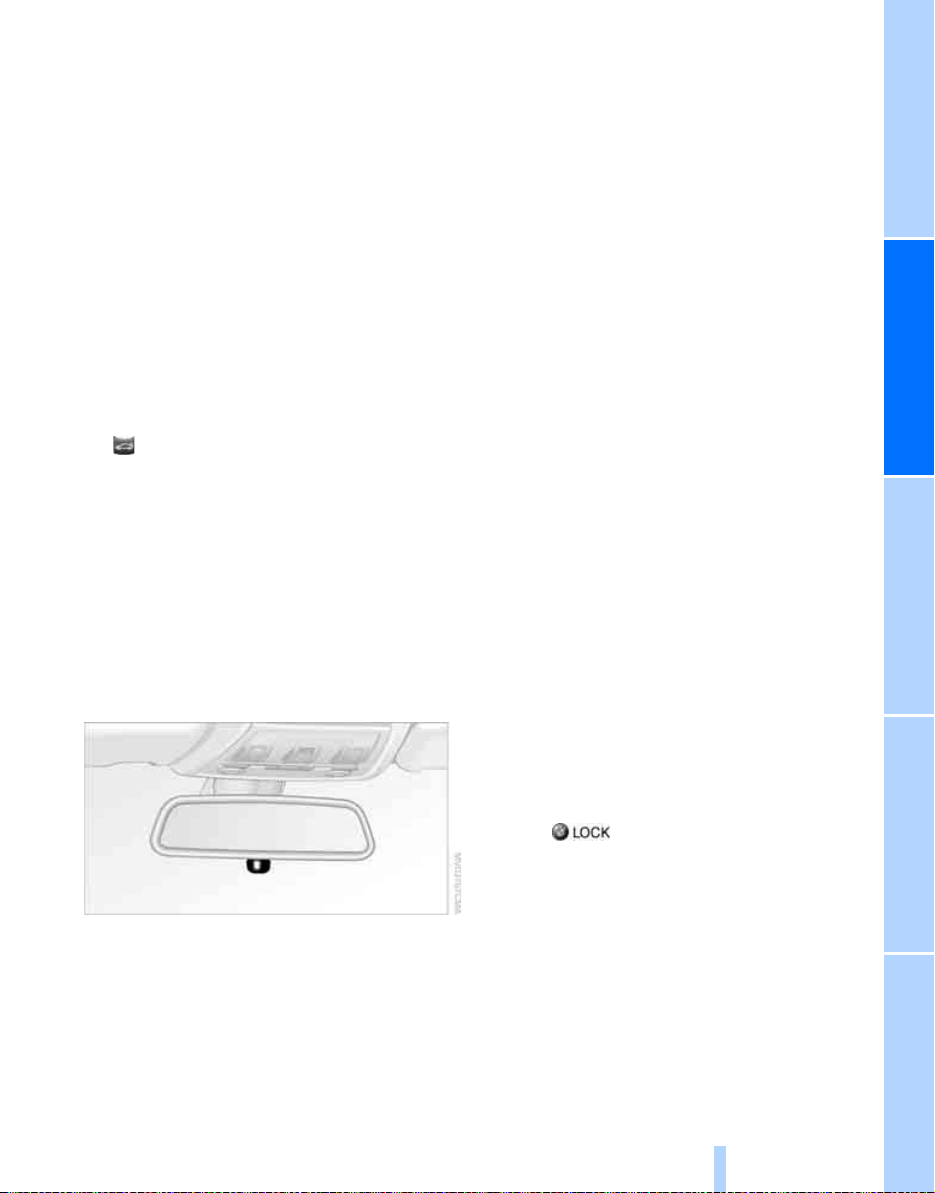
Interior rearview mirror
Manual adjustment
The mirrors can also be adjusted manually:
press the edge of the glass.
To prevent the exterior mirrors on this
vehicle from being damaged, always fold
them in by hand before entering an automatic
car wash.<
Automatic heating*
At outside temperatures below a certain limit,
both exterior mirrors are automatically heated
while the engine is running or the ignition
switched on.
Turn the knob to reduce glare from the headlamps of cars behind you when driving at night.
Automatically dimming mirrors, refer to
page 99.
37
Reference At a glanceControlsDriving tipsMobility
Page 40

Steering wheel
Online Edition for Part-No. 01 41 0 159 813 - © 09/05 BMW AG
Adjustments
Do not adjust the steering wheel position
while the car is in motion, or an accident
may result from any unexpected movement.<
Adjustments
1. Fold the lever down.
2. Move the steering wheel to the preferred
height and angle to suit your seated position.
3. Swing the lever back up.
Do not use force to swing the lever
back up, otherwise the mechanism
will be damaged.<
Electric steering wheel lock
The steering wheel locks or unlocks automatically when the remote control is removed or
inserted, refer to page 42.
38
Page 41

Transporting children safely
Online Edition for Part-No. 01 41 0 159 813 - © 09/05 BMW AG
The right place for children
Do not leave children unattended in the
vehicle, otherwise they could endanger
themselves and/or other persons by opening
the doors, for example.<
The rear center seat is not suitable for installing
universal child-restraint systems for all age
groups, approved for the age group in question.
Children always in the rear
Accident research has shown that the safest
place for children is on the rear seats.
Children under the age of 13 or smaller
than 5 ft/150 cm may be transported only
in the rear in suitable child-restraint systems
appropriate for their age, weight and size. Otherwise there is an increased risk of injury in the
event of an accident.<
Children 13 years of age or older must be buckled in with a safety belt as soon as there no
longer is any child-restraint system that is
appropriate for their age, size and weight.
All rear seats in your vehicle meet the recommendations of the SAE J1819 standard for
safely mounting child-restraint systems in
motor vehicles.
Exception for front passenger seat
Should it be necessary to use a child-
restraint system on the front passenger
seat, the front and side airbags must be deactivated. Otherwise, a child traveling on that seat
will be at an increased risk of injury if the airbags
are triggered off, even with a child-restraint system. Your BMW Center will be glad to advise
you.<
For more information on automatic deactivation
of the front passenger airbags refer to page 74.
Installing child-restraint systems
Observe the child-restraint system man-
ufacturer's instructions for selecting,
installing and using child-restraint systems.
Otherwise the protective effect may be diminished.<
Standard child-restraint systems are designed
to be secured with a lap belt or with the lap-belt
section of a lap-and-shoulder belt. Incorrectly
or improperly installed child-restraint systems
can increase the risk of injury to children.
Always follow the installation instructions for
the system with the greatest care.
On the front passenger's seat
Before installing a child-restraint system
on the front passenger's seat, make sure
that the front and side airbags for the front passenger are deactivated, otherwise there is an
increased risk of injury if the airbags deploy.<
Seat height
Before installing a universal child-restraint system, move the front passenger's seat up as far
as it will go to ensure that the safety belt will be
ideally positioned. Do not change the seat
height afterward.
Backrest width
The backrest width of the front passenger
seat must be adjusted to its widest setting, otherwise the stability of the child seat on
the front passenger seat is limited.<
1. Adjust the backrest width to its widest set-
ting, refer to page 33.
2. Install the child seat.
39
Reference At a glanceControlsDriving tipsMobility
Page 42

Child seat security
Online Edition for Part-No. 01 41 0 159 813 - © 09/05 BMW AG
Placement of the tether strap
All rear safety belts and the front passenger's
safety belt can be prevented from being pulled
out in order to fasten child-restraint systems.
To lock the safety belt
1. Secure the child-restraint system with the
belt.
2. Pull the belt strap all the way out.
3. Allow the belt strap to retract and pull it taut
against the child-restraint system.
The safety belt is locked.
Transporting children safely
To unlock the safety belt
1. Open the belt buckle
2. Remove the child-restraint system.
3. Allow the safety belt strap to retract all the
way.
Fold the anchors upward before using them.
1. Push the head restraint upward.
2. Guide the tether strap through the mount-
ing for the head restraint.
3. Push the head restraint into its lowermost
position.
LATCH child-restraint fixing system
LATCH: Lower Anchor and Tethers for CHildren.
When installing a LATCH child seat, comply with the system manufacturer's oper-
ating and safety instructions.<
Rear seats with through-loading
system
Child-restraint system with tether
strap
There are three additional anchors for childrestraint systems with tether straps, see
arrows.
40
The anchor points for the LATCH childrestraint fixing system are located behind the
indicated protective caps. Flip up the corresponding caps.
Page 43

Rear seats without through-loading
Online Edition for Part-No. 01 41 0 159 813 - © 09/05 BMW AG
system
The anchor points for the LATCH childrestraint fixing system can be found at the locations marked by the arrows. They are not visible
from the outside.
On journeys
Child-safety locks for rear doors
Slide down the safety lever on the rear doors:
The door can now be opened from the outside
only.
Safety switch for power windows
Press the safety switch for the power windows,
refer to page 28, if children are traveling on the
rear seat.
41
Reference At a glanceControlsDriving tipsMobility
Page 44

Driving
Online Edition for Part-No. 01 41 0 159 813 - © 09/05 BMW AG
Ignition lock
Driving
Insert the remote control all the way into the
ignition lock.
> Radio readiness switches on.
Individual electrical consumers can operate.
> The electric steering wheel lock disen-
gages audibly.
Insert the remote control into the ignition
lock before you move the vehicle, otherwise the electric steering wheel lock will not disengage and you will not be able to steer the
car.<
Removing the remote control from the
ignition lock
Press the remote control in briefly; it is ejected
part of the way.
At the same time:
> The ignition switches off if it was on before-
hand.
> The electric steering wheel lock engages
audibly.
Automatic transmission
You cannot take out the remote control unless
the selector lever is in the P position: interlock.
Start/stop button
Each time the start/stop button is pressed,
radio readiness or the ignition is switched on or
off.
Briefly pressing the start/stop button
while the brake or clutch is depressed
starts the engine.<
Radio readiness
Individual electrical consumers can operate.
The time and the outside temperature are displayed in the instrument cluster.
Radio readiness is switched off automatically:
> Immediately when the remote control is
removed from the ignition lock
> In cars with convenient access
ing the surface above the door lock, refer to
Locking on page 26
Ignition on
Most of the indicator and warning lamps in the
indicator area 1 of the instrument cluster, refer
to page 13, light up and remain on for different
lengths of time.
Radio readiness and ignition off
All indicator and warning lamps in the instrument cluster go out.
*, by touch-
42
Page 45

Starting the engine
Online Edition for Part-No. 01 41 0 159 813 - © 09/05 BMW AG
Do not run the engine in closed rooms,
otherwise the inhaling of toxic exhaust
gases can cause unconsciousness and death.
The exhaust gases contain carbon monoxide,
an odorless and colorless, but highly toxic gas.
Never leave an unattended vehicle with the
engine running, otherwise such a vehicle represents a potential safety hazard.
Before leaving the car with the engine running,
place the transmission in idle or move the
selector lever to position P and apply the handbrake to prevent the car from moving.<
When starting the engine, do not press the
accelerator pedal.
Do not allow the engine to warm up by leaving it
running while the vehicle remains stationary.
Instead, begin to drive immediately at a moderate engine speed.
Do not depress either the brake or the
clutch until you are ready to start the
engine. The engine is started immediately
when you briefly touch the start/stop button
and depress the brake if the car has automatic
transmission, or the clutch if the car has manual
transmission.<
Manual transmission
1. Apply the handbrake.
2. Depress the clutch and shift to idle position.
3. Briefly press the start/stop button.
The starter operates automatically for a certain
time, and stops automatically as soon as the
engine has started.
Automatic transmission
1. Depress the brake.
2. Move the selector lever to position P.
3. Briefly press the start/stop button.
The starter operates automatically for a certain
time, and stops automatically as soon as the
engine has started.
Sequential manual gearbox SMG*
1. Depress the brake.
2. Engage selector lever position N and make
sure that this position is displayed in the
instrument cluster.
3. Start the engine.
The starter operates automatically for a certain
time, and stops automatically as soon as the
engine has started.
If the engine does not start, depress the
brake and push the selector lever to the
right, then engage position N. Observe the display in the instrument cluster while doing so.<
Special starting conditions
In the following situations, press the accelerator
pedal halfway down when starting the engine:
> If the engine does not start on the first
attempt, for instance when it is extremely
hot or cold.
> If the engine is started at very low tempera-
tures, below approx. + 57/–156, at high
altitudes above approx. 3,300 ft/1,000 m.
Avoid frequent starting in quick succes-
sion or repeated start attempts in which
the engine does not start. Otherwise, the fuel is
not burned or inadequately burned and there is
a danger of overheating and damaging the catalytic converter.<
Switching off the engine
Always take the remote control with you
when you leave the vehicle.
When parking on a downhill incline, apply the
43
Reference At a glanceControlsDriving tipsMobility
Page 46

handbrake, otherwise the vehicle could roll
Online Edition for Part-No. 01 41 0 159 813 - © 09/05 BMW AG
away.<
Manual transmission
1. Apply the handbrake.
Driving
2. With the car at a standstill, briefly press the
start/stop button.
3. Shift into first gear or reverse.
Automatic transmission
1. With the car at a standstill, move the selec-
tor lever to position P.
2. Briefly press the start/stop button.
3. Apply the handbrake.
Sequential manual gearbox SMG
1. Apply the handbrake.
2. Engage a drive position.
3. Briefly press the start/stop button.
If the engine is switched off while N is engaged,
this will be signaled visually and acoustically.
Handbrake
The handbrake is primarily intended to prevent
the vehicle from rolling while parked; it brakes
the rear wheels.
Releasing
Pull slightly upwards, press the button and
lower the lever.
In exceptional cases, if the handbrake has
to be used to slow or stop the car, do not
pull the lever up too hard. In doing so, continuously press the button of the handbrake lever.
Otherwise, too violent an application of the
handbrake can overbrake the rear axle and
cause the rear of the car to swerve.<
To prevent corrosion and one-sided brak-
ing action, occasionally apply the handbrake lightly when the vehicle is slowly coming
to a stop if the traffic conditions are suitable.
The brake lamps do not light up when the handbrake is applied.<
Manual transmission
Indicator lamp
The indicator lamp is lit, and when you
drive off an acoustic signal sounds in
addition. The handbrake is still applied.
Indicator lamp for Canadian models.
Applying
The lever locks in position automatically.
44
When shifting into 5th or 6th gear, press
the gearshift lever to the right. Otherwise
the engine could be damaged if you inadvertently shift into 3rd or 4th gear.<
Page 47

Reverse gear
Online Edition for Part-No. 01 41 0 159 813 - © 09/05 BMW AG
Select only when the vehicle is stationary.
When the gearshift lever is pressed to the left, a
slight resistance has to be overcome.
Sequential manual gearbox SMG*
The concept
The sequential manual gearbox SMG is an
automated transmission in which operation of
the clutch and gearshifts are performed by an
electro-hydraulic system.
SMG is operated via the selector lever in the
center console and two shift paddles on the
steering wheel.
It offers you the following functions:
> Choice of manual or automatic operation:
sequential mode or Drive mode
> Choice of two driving programs: Normal or
Sport, refer to Dynamic Driving Control,
page 46
> Automatic downshifting and prevention of
misshifting in sequential mode as well
> Acceleration assistant, refer to page 47
Selector lever positions
> D: Drive mode or sequential mode
N is automatically selected when the
driver's door is opened while the engine is
running, as long as the pedals, shift paddles and
selector lever are not operated.
This is indicated by an acoustic signal and a
flashing N in the instrument cluster.<
Gear indicator
R N 1 to 6
The gear currently engaged is displayed, preceded by a D in Drive mode.
This indicator is the only way you can
confirm whether or not the desired selector lever position is engaged.<
Shiftlock
Before moving the lever away from N with the
vehicle stationary, first depress the brake; otherwise the desired gearshift will not be carried
out.
The current selector lever position can be seen
on the center console.
> R: Reverse gear
> N: Neutral, idle
> One-touch functions for sequential mode:
+: manual upshifting
–: manual downshifting
R Reverse
Select only when the vehicle is stationary.
Gear-change mode
The gears can be changed in two different
ways.
> Sequential mode
Gears are shifted by means of the shift paddles or the selector lever.
> D Drive mode
All forward gears are shifted automatically.
You can switch from one mode to the other by
pressing the selector lever towards the right in
the direction of D.
45
Reference At a glanceControlsDriving tipsMobility
Page 48

Sequential mode
Online Edition for Part-No. 01 41 0 159 813 - © 09/05 BMW AG
After every engine start, sequential mode is
activated when you press the selector lever
towards the right while the brake is depressed.
You can shift up or down using the shift paddles
Driving
or the selector lever. You do not need to lift your
foot from the accelerator pedal while doing so.
It is also possible to start off in second gear, e.g.
on slippery surfaces.
SMG assists you in the following situations:
> Upshifts and downshifts are executed only
when they will result in a plausible combination of engine and vehicle speed; for example, a downshift that would cause the
engine to overrev cannot be executed by
the system.
> The system shifts down into first gear auto-
matically when the vehicle comes to a stop.
> The system shifts down automatically just
before the engine speed falls below the
minimum speed required for a certain gear;
the driver does not need to intervene.
Shifting gears via selector lever
> Pull the selector lever backwards to shift up.
> Push it forward to shift down.
To switch from sequential mode to Drive mode:
press the selector lever towards the right in the
direction of D.
Kick-down: to accelerate rapidly, e.g. when
passing another vehicle, depress the accelerator pedal all the way. You will achieve maximum
acceleration.
To switch back to sequential mode: press the
selector lever again towards the right in the
direction of D or shift gears via the shift paddles
or the selector lever.
On uphill slopes, drive off without delay.
Do not hold the vehicle in place by
depressing the accelerator pedal; engage the
handbrake instead. Otherwise, the transmission could overheat.<
Dynamic Driving Control
Dynamic Driving Control enables you to drive
your BMW in an even more performance-oriented manner at the touch of a button:
> Gears are shifted more quickly.
> In Drive mode, the engine speed range is
utilized optimally.
Activating the system
Shifting gears via the shift paddles on
the steering wheel
> Pull one of the shift paddles to shift up.
> Press it to shift down.
D Drive mode
In Drive mode, all forward gears are shifted
automatically.
46
Press the SPORT button while the ignition is
switched on. The LED in the button lights up.
Deactivating the system
> Press the SPORT button again or
> engage reverse gear or
> switch off the engine.
The LED in the button goes out.
Page 49

Acceleration assistant
Online Edition for Part-No. 01 41 0 159 813 - © 09/05 BMW AG
The acceleration assistant provides for optimal,
racing-style acceleration when starting off on a
non-slippery surface.
Do not use the acceleration assistant too
frequently, otherwise components could
wear prematurely.<
1. Activate Dynamic Driving Control.
2. Deactivate DSC, refer to page 68.
3. Quickly depress the accelerator pedal all
the way: kick-down. The optimal engine
speed for pulling away is achieved.
To maintain driving stability, reactivate
DSC afterward.<
Automatic transmission with Steptronic*
In addition to fully automatic operation, you can
also manually shift with the Steptronic, refer to
page 48.
Vehicle parking
To prevent the vehicle from rolling,
always select position P and apply the
handbrake before leaving the vehicle with the
engine running.<
Displays in the instrument cluster
P R N D DS M1 to M6
The selector lever position is displayed, or the
current gear in the manual mode.
Changing selector lever positions
> With the ignition switched on or the engine
running, the selector lever can be moved
out of position P: interlock.
> Before moving the lever away from P or N
with the vehicle stationary, first depress the
brake; otherwise the selector lever will
refuse to move: shiftlock.
To prevent the vehicle from creeping
after you select a driving position,
depress the brake until you are ready to
start.<
Disengaging the remote control
In order to remove the remote control from the
ignition lock, you must first move the selector
lever to position P and switch off the engine:
interlock.
Selector lever positions
P R N D M/S + –
A lock prevents you from inadvertently engaging selector lever positions R and P. To cancel
the lock, press the button on the front of the
selector lever, refer to arrow.
P Park
Select only when the vehicle is stationary. The
rear wheels are locked.
47
Reference At a glanceControlsDriving tipsMobility
Page 50

R Reverse
Online Edition for Part-No. 01 41 0 159 813 - © 09/05 BMW AG
Select only when the vehicle is stationary.
N Neutral, idle
You can select this in a car wash, for example.
Driving
The vehicle can roll.
D Drive, automatic position
Position for normal vehicle operation. All forward gears are selected automatically.
Under normal operating conditions, fuel consumption is lowest when you are driving in position D.
Kick-down
Kick-down enables you to achieve maximum
performance.
Press the accelerator pedal beyond the fullthrottle resistance point.
Manual operation and Sport program
M/S
gear selected appears briefly in the instrument
cluster, followed by the gear actually in use.
To use the automatic function again, move the
selector lever to the right into position D.
Overriding selector lever lock
Should the selector lever refuse to move out of
position P although the button on the selector
lever is pressed, the selector lever lock can be
overridden:
1. Unclip the sleeve of the selector lever.
2. Pull the sleeve up over the selector lever
until the sleeve is inside out.
3. Using the screwdriver from the onboard
tool kit, refer to page 125, press the red
lever while moving the selector lever to the
desired position.
Move selector lever from position D toward the
left into the M/S shifting slot:
The sport program is activated and DS appears
in the instrument cluster. This position is recommended for a performance-oriented driving
style.
When you press the selector lever forwards or
backwards, the manual mode is activated and
Steptronic changes gear. The instrument cluster shows M1 through M6.
Upshifts and downshifts are executed only
when they will result in a plausible combination
of engine and vehicle speed; thus, for example,
a downshift that would cause the engine to
overrev will not be executed by the system. The
48
Turn signals/ headlamp flasher
1 High beams
2 Headlamp flasher
3 Turn signals
Page 51

Using turn signals
Online Edition for Part-No. 01 41 0 159 813 - © 09/05 BMW AG
Press the lever beyond the resistance point.
To turn off manually, press the lever to the
resistance point.
Unusually rapid flashing of the indicator
lamp indicates that a turn signal indicator
has failed.
After switching off the ignition, make sure that
the roadside parking lamps are not switched
on.<
Indicating a turn briefly
Press the lever as far as the resistance point for
as long as you wish to indicate a turn.
Triple turn signal activation
Press the lever as far as the resistance point.
The turn signals flash three times.
You can activate or deactivate this function.
Operating principle, refer to page 61.
1. Lightly push button 1 in the turn indicator
stalk up or down repeatedly until the symbol
appears in the display accompanied by the
word "SET".
3. Lightly push button 1 in the turn indicator
stalk down repeatedly until the symbol
appears in the display.
4. Press button 2.
5. Use button 1 to select:
>
Brief indication of a turn.
>
Triple turn signal.
6. Press button 2.
The setting is stored.
Wiper system
2. Press button 2.
1 Switching on wipers
2 Switching off wipers or brief wipe
3 Activating/deactivating intermittent wipe or
rain sensor
4 Cleaning windshield and headlamps*
5 Setting speed for intermittent wipe, or sen-
sitivity of the rain sensor
*
Switching on wipers
The lever automatically returns to its initial position when released.
49
Reference At a glanceControlsDriving tipsMobility
Page 52

Normal wiper speed
Online Edition for Part-No. 01 41 0 159 813 - © 09/05 BMW AG
Press once.
The system switches to operation in the intermittent mode when the vehicle is stationary.
Driving
Fast wiper speed
Press twice or press beyond the resistance
point.
The system switches to normal speed when the
vehicle is stationary.
Intermittent wipe or rain sensor*
If the car is not equipped with a rain sensor, the
intermittent-wipe time is a preset.
If the car is equipped with a rain sensor, the time
between wipes is controlled automatically and
depends on the intensity of the rainfall. The
sensor is mounted on the windshield, directly in
front of the interior rearview mirror.
Activating intermittent wipe or rain
sensor
Cleaning windshield and headlamps*
Pull lever 4.
Washer fluid is sprayed onto the windshield and
the wipers are operated for a short time.
When the vehicle lighting system is switched
on, the headlamps are cleaned at regular and
appropriate intervals.
Do not use the washers if there is any
danger that the fluid will freeze on the
windshield. If you do, your vision could be
obscured. Antifreeze should therefore be
added to the fluid, refer to Washer fluid.
Do not use the washers when the washer fluid
reservoir is empty, otherwise you will damage
the washer pump.<
Windshield washer nozzles
The windshield washer nozzles are heated
automatically while the engine is running or the
ignition switched on.
Washer fluid
Washer fluid antifreeze is flammable.
Always keep it well away from sparks and
open flames, and store it in the tightly closed
original container, well out of the reach of children. Comply with the instructions on the container.<
Press button 3. The LED in the button lights up.
Setting speed for intermittent wipe or
sensitivity of the rain sensor
Slide switch 5 up or down.
Deactivating intermittent wipe or rain
sensor
Press button 3 again. The LED goes out.
Deactivate the rain sensor before entering an automatic car wash. Failure to do
so could result in damage caused by undesired
wiper activation.<
50
Washer fluid reservoir
Fill with water and, if required, with a washer
antifreeze, according to manufacturer's recommendations.
Page 53

Mix the water and antifreeze before filling
Online Edition for Part-No. 01 41 0 159 813 - © 09/05 BMW AG
the washer fluid reservoir to make sure
the correct concentration is maintained.<
Capacity
Approx. 6.3 US quarts/6 liters.
Cruise control*
One lever for all functions
The concept
Cruise control is available for use at speeds of
approx. 20 mph or 30 km/h. The car then stores
and maintains the speed that you specify using
the lever on the steering column. In order to
maintain the specified speed, the system
brakes the vehicle when the engine braking
effect is insufficient on downhill gradients.
Do not use cruise control when driving
conditions are unfavorable for driving at a
constant speed. Otherwise you could lose control of the vehicle and cause an accident as a
result. Unfavorable driving conditions include,
for example, winding roads, heavy traffic or a
poor road surface, e.g. snow, rain, ice or loose
material.<
Manual transmission/SMG
You can shift gears while cruise control is activated. An indicator lamp notifies you that you
should shift gears when you drive for an
extended period at very high or very low engine
speeds, or the system is deactivated.
In Drive mode, the SMG acts similarly to an
automatic transmission in position D.
1 Storing and maintaining speed or accelerat-
ing
2 Storing and maintaining speed or deceler-
ating
3 Deactivating cruise control
4 Resuming a speed stored beforehand
Maintaining current speed
Tap the lever, arrow 1, or pull it briefly, arrow 2.
The car's current speed is stored and maintained. It is displayed in the speedometer and
briefly in the instrument cluster.
On uphill gradients, it may prove impossible to
maintain the set speed if current engine power
output is insufficient. If the engine braking
effect is insufficient on downhill slopes, the system will brake the vehicle slightly.
Increasing desired speed
Repeatedly press the lever to the resistance
point or beyond, arrow 1, until the desired
speed is reached.
> Each time the lever is pressed to the resis-
tance point, the desired speed is increased
by approx. 1 mph or 1 km/h.
> Each time the lever is pressed beyond the
resistance point, the desired speed is
increased by up to 5 mph or 10 km/h.
The system stores and maintains the speed.
Accelerating using the lever
Accelerating slightly:
Press the lever to the resistance point, arrow 1,
until the desired speed is reached.
Accelerating significantly:
51
Reference At a glanceControlsDriving tipsMobility
Page 54

Press the lever beyond the resistance point,
Online Edition for Part-No. 01 41 0 159 813 - © 09/05 BMW AG
arrow 1, until the desired speed is reached.
The vehicle accelerates without pressure on
the accelerator pedal. The system stores and
maintains the speed.
Driving
Decreasing desired speed
Repeatedly pull the lever to the resistance point
or beyond, arrow 2, until the desired speed is
displayed.
> Each time the lever is pulled to the resis-
tance point, the desired speed is decreased
by approx. 1 mph or 1 km/h.
> Each time the lever is pulled beyond the
resistance point, the desired speed is
reduced by up to 5 mph or 10 km/ h unt il the
minimum speed of 20 mph or 30 km/h is
achieved.
The system stores and maintains the speed.
If the speed is to be reduced significantly,
depress the brake; otherwise, decelera-
tion may be insufficient and dangerous situations could result.<
Deactivating cruise control
Tap the lever upwards or downwards, arrow 3.
The displays in the speedometer disappear.
In addition, the system is automatically deactivated:
> When you brake the vehicle
> When you switch gears very slowly or shift
to idle in cars with manual transmission
> When you select the automatic transmis-
sion's/SMG's neutral position N
> When you activate DTC or deactivate DSC
> When DSC or ABS is intervening
Cruise control is not deactivated by depressing
the accelerator pedal. Once the accelerator
pedal is released, the stored speed is achieved
again and maintained.
Warning lamp
The warning lamp comes on when
cruise control has been automatically
deactivated by engaging the handbrake or as a
result of DSC intervening.
Resuming a speed stored beforehand
Briefly press the button, arrow 4. the stored
speed is resumed and maintained.
In the following instances, the stored speed is
deleted and can no longer be resumed:
> When driving stability control systems are
intervening
> In cars with manual transmission: when you
shift gears very slowly or shift to idle position
> With automatic transmission/SMG: when
you engage selector lever position N
> When the ignition is switched off
Displays in the instrument cluster
1 Stored speed
2 Selected speed is displayed briefly
If --- mph or --- km/h temporarily appears
in the instrument cluster display, it is possible that the system prerequisites for operation
are currently not met.
Calling up Check Control messages, refer to
page 66.<
Malfunction
The warning lamp comes on when
the system has failed. You can find
more information starting on
page 136.
52
Page 55

Active cruise control*
Online Edition for Part-No. 01 41 0 159 813 - © 09/05 BMW AG
The concept
With active cruise control, you can select a
desired speed which is not only automatically
maintained when driving on open roadways, but
also varied to maintain a selected distance setting as slower traffic is encountered.
Active cruise control is a technological advance
over the familiar cruise control and is a welcome
relief from the constant adjustment of speed
that can accompany driving in traffic on highways or other high-speed thoroughfares. Especially on longer trips, the system can reduce
fatigue and tension, while increasing your
enjoyment of driving. Please use it safely and
responsibly.
Within the limits of its capability, the system
automatically adapts the car's speed to that of a
slower vehicle in front of you. You can specify
the distance to be maintained from the vehicle
in front in four stages. For safety reasons, the
distance is speed-dependent. Based on your
selected distance setting, the system automatically decreases the throttle setting and lightly
applies the brakes if necessary. The vehicle
brake lamps will automatically illuminate to signal a following driver to take action. In addition,
it may be necessary for the vehicle or the driver
to downshift, depending on the kind of transmission your vehicle is equipped with, to maintain the distance setting selected. If the vehicle
ahead speeds up or when the lane ahead
becomes clear, your vehicle will accelerate to
the speed you have selected by increasing the
throttle setting and shifting gears automatically
or by the driver as needed. Your selected speed
will be held when driving downhill, too.
Since this active cruise control system is a new
technology and operates differently from conventional cruise control systems which you may
be accustomed to, you are strongly urged to
read all of the pages relating to this system
before use. Pay special attention to the System
limitations section beginning on page 57.
Braking sensation
The system's automatic brake operation results
in a braking sensation that is slightly different
from what you feel when you brake the vehicle
yourself in a similar situation. Possible noises
during automatic deceleration are normal.
Manual transmission/SMG
You can shift gears while cruise control is activated. An indicator lamp notifies you that you
should shift gears when you drive for an
extended period at very high or very low engine
speeds, or the system is deactivated.
In Drive mode, the SMG acts similarly to an
automatic transmission in position D.
Range of applications
The minimum desired speed is 20 mph or
30 km/h, and the maximum desired speed is
110 mph or 180 km/h.
As with conventional cruise control sys-
tems, active cruise control in no way
diminishes or substitutes for the driver’s own
personal responsibility, alertness and awareness in adjusting speed, braking or otherwise
controlling the vehicle. The driver should
decide when to use the system on the basis of
road, traffic, visibility, and weather conditions.
Active cruise control is intended for use on
highway-type roadways where traffic is moving
relatively smoothly. Do not use this system in
city driving; heavy traffic such as during rush
hour; on curvy, winding roads, slippery roads or
roads with sharp curves such as highway offramps; during inclement weather such as snow,
strong rain or fog; or when entering interchanges, service/parking areas or toll booths.
It is also important to regulate your vehicle's
speed and distance setting within applicable
legal limits. Always be ready to take action or
apply the brakes if necessary, especially when
the system is actively following a vehicle in front
of you. Otherwise, driving conditions could
result which violate the law or pose a risk of
accident.<
53
Reference At a glanceControlsDriving tipsMobility
Page 56

One lever for all functions
Online Edition for Part-No. 01 41 0 159 813 - © 09/05 BMW AG
Driving
1 Store and increase desired speed
2 Store and decrease desired speed
3 Deactivate system, refer to page 55
4 Resume stored desired speed and dis-
tance, refer to page 56
5 Select distance to vehicle driving ahead,
refer to page 55
e.g. when quickly approaching a truck or when
another vehicle swerves into your lane, cannot
be compensated for by the system.<
Increasing in increments
Repeatedly tap the lever to the resistance point
or beyond, arrow 1, until the desired speed is
reached.
> Each time the lever is tapped to the resis-
tance point, the desired speed is increased
by approx. 1 mph or 1 km/h.
> Each time the lever is tapped beyond the
resistance point, the desired speed is
increased by up to 5 mph or 10 km/h until
the maximum speed of 110 mph or
180 km/h is achieved.
The speed then displayed is stored and
achieved on a clear road.
Maintaining current speed
Briefly press the lever, arrow 1, or briefly pull it,
arrow 2, at a driving speed of more than approx.
20 mph or 30 km/h.
The car's current speed is stored and maintained. It is displayed in the speedometer and
briefly in the instrument cluster.
On uphill gradients, it may prove impossible to
maintain the set speed if current engine power
output is insufficient. If the engine braking
effect is insufficient on downhill slopes, the system will brake the vehicle slightly.
Adjusting desired speed
Adjust your desired speed to the traffic
conditions and remain ready to brake at
all times, otherwise there is a risk of accident.
Great differences in speed to the vehicle ahead,
Increasing continuously
Repeatedly press the lever to the resistance
point or beyond, arrow 1, until the desired
speed is reached.
The speed then displayed is stored and
reached as soon as the road ahead of you is
clear.
Decreasing in increments
Repeatedly pull the lever to the resistance point
or beyond, arrow 2, until the desired speed is
reached.
> Each time the lever is pulled to the resis-
tance point, the desired speed is decreased
by approx. 1 mph or 1 km/h.
> Each time the lever is pulled beyond the
resistance point, the desired speed is
reduced by up to 5 mph or 10 km/ h unt il the
minimum speed of 20 mph or 30 km/h is
achieved.
The speed then displayed is stored and
achieved on a clear road.
54
Page 57

Selecting distance
Online Edition for Part-No. 01 41 0 159 813 - © 09/05 BMW AG
Deactivating cruise control
> Press downward:
Increase distance
> Press upward:
Decrease distance.
The selected distance is displayed in the instrument cluster.
Distance 1
Distance 2
Distance 3
This distance is always set when
the system is used for the first
time after starting the engine.
Distance 4
Use good judgement to select the appro-
priate following distance given road conditions, traffic, applicable laws and driving recommendations for safe following distance.
Otherwise, you may be in violation of the law or
an accident could result.<
Press the lever upward or downward, arrow 3.
The displays in the speedometer disappear.
In addition, the system is automatically deactivated:
> When you brake the vehicle
> When the speed is reduced to below
20 mph or 30 km/h due to a traffic situation
> When you switch gears very slowly or shift
to idle in cars with manual transmission
> When you select the automatic transmis-
sion's/SMG's neutral position N
> When you activate the Dynamic Traction
Control DTC
> When you deactivate the Dynamic Stability
Control DSC
> When DSC or ABS is intervening
> When the system does not recognize any
objects for a longer period of time, e.g. on
infrequently traveled roads without a shoulder or guard rails, or if the radar sensor is
covered with dirt, refer to page 56
> When you apply the handbrake
When the system is deactivated, you
must brake the vehicle yourself and/or
maneuver as necessary, otherwise there is a
risk of accident.<
Warning lamp
The warning lamp comes on when
active cruise control has been auto-
matically deactivated due to a driving
speed below 20 mph or 30 km/h, an application
of the handbrake or a DSC intervention.
55
Reference At a glanceControlsDriving tipsMobility
Page 58

Resuming stored desired speed and
Online Edition for Part-No. 01 41 0 159 813 - © 09/05 BMW AG
distance
Briefly press the button, arrow 4.
The stored speed and distance are regained
and maintained.
Driving
In the following instances, the stored speed is
deleted and can no longer be resumed:
> When driving stability control systems are
intervening
> In cars with manual transmission: when you
shift gears very slowly or shift to idle position
> With automatic transmission/SMG: when
you engage selector lever position N
> When the ignition is switched off
Displays in the instrument cluster
are currently not met. Calling up Check Control
messages, refer to page 66.<
Warning lamps
The indicator 2 flashes in red; a
signal sounds.
The system indicates that you
must brake and/or maneuver the
vehicle yourself. Active cruise control cannot automatically restore the distance to
the vehicle ahead.
This indicator does not release you from your
responsibility to adapt your desired speed and
driving style to prevailing driving conditions.
The indicator 2 flashes in yellow.
The prerequisites for operating
active cruise control are not met,
e.g. as a result of ABS or DSC
interventions. Active cruise control
is deactivated. You can reactivate the system, if
desired, by tapping or pulling the lever when
road and traffic conditions permit. It is not possible to resume a stored speed.
Radar sensor
1 Stored desired speed
2 Shows yellow: vehicle detected ahead
Flashes in red: system cannot maintain distance; driver must brake the vehicle
Flashes in yellow: driving stability control
systems are intervening; cruise control is
deactivated
3 Selected distance to vehicle ahead
The indicator lights up as soon as the system is activated.
4 Selected desired speed is temporarily dis-
played
If --- mph or --- km/h temporarily appears
in the instrument cluster display, it is pos-
sible that the system prerequisites for operation
56
The sensor's ability to detect vehicles ahead
may be restricted as a result of heavy rain, dirt,
snow or ice. If necessary, clean the radar sensor
located in the front bumper, see arrow. Be sure
to use particular care when removing any layers
of snow or ice from the sensor.
When the radar sensor is not properly positioned, active cruise control cannot be activated
at all.
Page 59

Malfunction
Online Edition for Part-No. 01 41 0 159 813 - © 09/05 BMW AG
The warning lamp comes on when
the system has failed. You can find
System limitations
more information starting on page 136.
Always remember that the range and abil-
ity of the system does have physical limitations. It will not apply the brakes or decelerate
your vehicle when there is a slow-moving vehicle, stopped vehicle or stationary object ahead
of you, as for example, at a traffic light or a
parked vehicle. Also, the system does not react
to oncoming traffic, pedestrians or other types
of potential traffic such as a rider on horseback.
It is also possible that the system may not
detect smaller moving objects such as motorcycles or bicycles. Be especially alert when
encountering any of these situations as the system will neither automatically brake, nor provide
a warning to you. Also, be aware that every
decrease in the distance setting allows your
vehicle to come closer to a vehicle in front of
you and requires a heightened amount of alertness.<
Active cruise control is not and must not
be used as a collision avoidance/warning
system.<
If while your vehicle is actively following a vehicle in front of you and the vehicle ahead speeds
up or the lane ahead becomes clear, then your
vehicle will accelerate to the speed you have
selected. Be aware that changing to a clear,
unobstructed lane will also result in your vehicle
accelerating.
Be certain to deactivate the system when
you pull into an exit lane for a highway offramp.<
Also, vehicles traveling in a staggered manner
on a highway may cause a delay in the system's
reaction to a vehicle in front of you or may cause
the system to react to a vehicle actually in the
lane next to you. Always be ready to take action
or apply the brakes if necessary.
While active cruise control is capable of
braking your vehicle automatically when
you approach a slower vehicle ahead, it is
important to be aware that the ability of the system to apply the brakes is also limited, e.g.
when you reduce your desired speed sharply.
The system cannot stop your vehicle. It uses
only a portion of braking system capacity and
does not utilize the full capacity of the vehicle
braking system. Therefore, the system cannot
decrease your speed for large differences in
speed between your vehicle and the vehicle
ahead. Examples: when you approach a vehicle
traveling at a much lower speed than your own
speed such as approaching a toll booth or when
a much slower vehicle cuts in front of you at
close range.<
Active cruise control can only decelerate the
vehicle to approx. 20 mph or 30 km/h.
57
Reference At a glanceControlsDriving tipsMobility
Page 60

Swerving vehicles
Online Edition for Part-No. 01 41 0 159 813 - © 09/05 BMW AG
Driving
When a vehicle moves from an adjacent lane
into your lane, active cruise control will not recognize this vehicle until it is fully in your lane
ahead of your vehicle.
When a vehicle ahead suddenly swerves
into your lane, the system may not be able
to maintain the selected distance automatically.
This also applies to great differences in speed
between you and vehicles ahead, e.g. when
quickly approaching a truck. There is a risk of
collision. Once the system has established that
a vehicle is indeed in front of you, it will indicate
that you must brake and/or maneuver the vehicle yourself. Take action yourself, otherwise
there is a risk of an accident.<
Behavior in curves
In approaching a curve, it is possible that active
cruise control would react briefly to a vehicle in
the adjacent lane. In addition, the system can
sense if your vehicle is in a curve and may not
accelerate. If your vehicle decelerates in either
case, you can choose to overcome the deceleration by briefly pressing the accelerator pedal.
Your responsibility
Your actions have priority at all times. When you
press the accelerator pedal while driving with
active cruise control, the automatic braking
function will be temporarily interrupted. Once
you release the accelerator pedal, the desired
speed or the selected distance to the vehicle
ahead is achieved again.
Do not leave your foot on the accelerator
pedal and make sure that no objects such
as floor mats are lying on the accelerator pedal.
Otherwise the system may not be able to brake
the vehicle.<
Because of the limited range of the system, it is
possible that in curves or on the peaks and valleys of hilly roads, a vehicle ahead may be recognized late, or not at all. Therefore, it is up to
the driver to select a speed that is prudent in
view of the curves and terrain of the roadway.
58
Page 61

Everything under control
Online Edition for Part-No. 01 41 0 159 813 - © 09/05 BMW AG
Odometer, outside temperature display, clock
1 Resetting trip odometer
2 Outside temperature display and clock
3 Odometer and trip odometer
Units of measure
To select the respective units of measure, miles
or km for the odometer as well as 7 or 6 for
the outside temperature, refer to page 62.
Outside temperature display, clock
Setting the time, refer to page 64.
Outside temperature warning
When the displayed temperature sinks to
approx. +377/+36, a signal sounds and a
warning lamp lights up. There is an increased
risk of black ice.
Black ice can also form at temperatures
above +377/+36. You should there-
fore drive carefully on bridges and shaded
roads, for example, otherwise there is an
increased risk of an accident.<
Odometer and trip odometer
Resetting trip odometer:
With the ignition switched on, press button 1 in
the instrument cluster.
When the vehicle is parked
If you still want to view the time, outside temperature and odometer reading briefly after the
remote control has been removed from the ignition lock:
Press button 1 in the instrument cluster.
Tachometer
Never force the engine speed up into the red
warning field, see arrow. In this range, the fuel
supply is interrupted to protect the engine.
Coolant temperature
A warning lamp will come on if the coolant, and
therefore the engine, becomes too hot.
Check coolant level, refer to page 121.
59
Reference At a glanceControlsDriving tipsMobility
Page 62

Energy Control
Online Edition for Part-No. 01 41 0 159 813 - © 09/05 BMW AG
Displays the current fuel consumption. This
allows you to see whether your current driving
style is conducive to fuel economy with minimum exhaust emissions.
Fuel gauge
Everything under control
Fuel tank capacity: approx. 15.9 US gallons/
60 liters. You can find information on refueling
on page 106.
If the tilt of the vehicle varies for a longer period,
when you are driving in mountainous areas, for
example, the indicator may fluctuate slightly.
Reserve
Once the fuel level has fallen to the reserve
zone of approx. 2.1 US gallons/8 liters, the indicator lamp and cruising range for the remaining
amount of fuel are displayed briefly. The indicator lamp remains permanently on if the remaining range is less than approx. 30 miles/50 km.
Refuel as soon as possible once your
cruising range falls below 30 miles/
50 km, otherwise engine functions are not
ensured and damage can occur.<
Computer
Displays in the instrument cluster
To call up the information, press the button in
the turn indicator stalk.
The following items of information are displayed in the order listed:
> Cruising range
> Average speed
> Average fuel consumption
To set the corresponding units of measure,
refer to Formats and units of measure on
page 62.
Cruising range
Displays the estimated cruising range available
with the remaining fuel. The range is calculated
on the basis of the way the car has been driven
over the last 18 miles/30 km and the amount of
fuel currently in the tank.
Be su re to re fu el as soo n a s p os si bl e o nce
your cruising range falls below 30 miles/
50 km, otherwise engine functions are not
ensured and damage can occur.<
Average speed
Periods with the vehicle parked and the engine
switched off are not included in the calculations
of average speed.
To reset average speed: press the button in the
turn indicator stalk for approx. 2 seconds.
Average fuel consumption
The average fuel consumption is calculated for
the time during which the engine is running.
60
Page 63

To reset average fuel consumption: press the
Online Edition for Part-No. 01 41 0 159 813 - © 09/05 BMW AG
button in the turn indicator stalk for approx.
2seconds.
Settings and information
Operating principle
1 Button for:
> Selecting display
> Setting values
2 Button for:
> Confirming selected display or set val-
ues
> Calling up computer information 60
3 When the lights are switched on: instrument
lighting brightness 78
4 Calling up Check Control 65
5 Checking engine oil level* 119
6 Initializing the Flat Tire Monitor 72
7 Setting the time 64
8 Setting the date 65
9 Viewing service requirement display 63
10 Setting formats and units of measure,
resetting to factory settings 62
11 Adjusting settings
> Confirmation signals when locking and
unlocking the vehicle 21
> Response during unlocking
procedure 20
> Automatic locking 22
> Pathway lighting 76
> Daytime driving lamps 77
> Triple turn signal activation 49
> Seat and mirror memory 35
61
Reference At a glanceControlsDriving tipsMobility
Page 64

Exiting displays
Online Edition for Part-No. 01 41 0 159 813 - © 09/05 BMW AG
The outside-temperature reading and the time
reappear when you press button 2 or if you
make no entries within approx. 15 seconds. If
required, complete the current setting first.
Formats and units of measure
You can set formats and units of measure. The
settings are stored for the remote control currently in use, refer also to Personal Profile on
page 19.
1. Lightly push button 1 in the turn indicator
stalk up or down repeatedly until the symbol
appears in the display accompanied by the
word "SET".
Everything under control
2. Press button 2.
3. Use button 1 to select desired format or
desired unit of measure, e.g. for fuel consumption.
> Fuel consumption: mpg, km/l,
l/100km
> Distance covered: mls, km
> Time: 12h, 24h mode
> Date: day.month dd.mm,
month/day mm/dd
> Temperature: 7, 6
4. Press button 2.
5. Use button 1 to make the setting.
6. Press button 2.
The setting is stored.
Resetting to factory settings
You can reset the settings for formats and units
of measure to factory settings. The settings are
stored for the remote control currently in use,
refer also to Personal Profile on page 19.
1. Lightly push button 1 in the turn indicator
stalk up or down repeatedly until the symbol
appears in the display accompanied by the
word "SET".
2. Press button 2.
3. Use button 1 to select "RESET".
62
Page 65

4. Press button 2 until is displayed.
Online Edition for Part-No. 01 41 0 159 813 - © 09/05 BMW AG
The settings are reset.
Service requirements
The remaining driving distance and the date of
the next scheduled service are displayed briefly
immediately after you start the engine or switch
on the ignition.
The extent of service work required can
be read out from the remote control by
your BMW Service Advisor.<
For certain maintenance operations, you can
view the respective distance remaining or due
date individually in the instrument cluster.
accompanied by the words "SERVICEINFO".
2. Press button 2.
3. Use button 1 to scroll through the individual
service items.
1. Lightly push button 1 in the turn indicator
stalk up or down repeatedly until the appropriate symbol appears in the display,
63
Reference At a glanceControlsDriving tipsMobility
Page 66

Possible displays
Online Edition for Part-No. 01 41 0 159 813 - © 09/05 BMW AG
Everything under control
1 Button for selecting functions
2 Service requirements
3 Engine oil
4 Exhaust emissions test
5 Roadworthiness test*
6 Microfilter
*
Clock
Setting the time
To set the 12h/24h mode, refer to Formats and
units of measure on page 62.
1. Lightly push button 1 in the turn indicator
stalk up or down repeatedly until the appro-
7 Spark plugs
8 Brakes, front
9 Brakes, rear
10 Brake fluid
More information on the BMW Maintenance
System can be found on page 123.
priate symbol appears in the display,
accompanied by the time and the word
"SET".
2. Press button 2.
3. Use button 1 to set the hours.
4. Press button 2.
5. Use button 1 to set the minutes.
6. Press button 2.
The system displays the new time.
7. Use button 2 to save the new time.
64
Page 67

Date
Online Edition for Part-No. 01 41 0 159 813 - © 09/05 BMW AG
Setting the date
To set the dd/mm or mm/dd date format, refer
to Formats and units of measure on page 62.
1. Lightly push button 1 in the turn indicator
stalk up or down repeatedly until the appropriate symbol appears in the display,
accompanied by the date and the word
"SET".
2. Press button 2.
3. Use button 1 to set the day of the month.
4. Press button 2.
5. Set the month and the year in the sam e way.
6. Press button 2.
The system displays the new date.
7. Use button 2 to save the new date.
Indicator and warning lamps can light up in both
the indicator area 1 and the display 2 in various
combinations and colors.
What to do in case of a malfunction
The meaning of each lamp in the event of a malfunction and tips on how to respond are listed
starting on page 136.
Hiding Check Control messages
Check Control
The concept
The Check Control monitors vehicle functions
and alerts you to any malfunctions in the systems monitored. Such a Check Control message includes indicator or warning lamps in the
instrument cluster and, in some circumstances,
an acoustic signal.
Press the button in the turn indicator stalk.
Some Check Control messages remain visible
until the malfunction in question has been rectified. They cannot be hidden. If several malfunctions occur at the same time, the Check Control
messages are displayed in succession.
Other Check Control messages are automatically hidden after approx. 20 seconds, but
remain stored.
65
Reference At a glanceControlsDriving tipsMobility
Page 68

indicates that Check Control messages have
Online Edition for Part-No. 01 41 0 159 813 - © 09/05 BMW AG
been stored. You can view the Check Control
messages whenever it is convenient for you.
Viewing stored Check Control
messages
Everything under control
1. Lightly push button 1 in the turn indicator
stalk up or down repeatedly until the appropriate symbol appears in the display,
accompanied by the words "CHECK CONTROL".
2. Press button 2.
"CHECK OK" appears if there are no Check
Control messages.
If a Check Control message has been
stored, the corresponding lamp comes on.
3. Lightly push button 1 to check for other
messages.
4. Press button 2.
The display again shows the outside temperature and the time.
66
Page 69

Technology for driving comfort and safety
Online Edition for Part-No. 01 41 0 159 813 - © 09/05 BMW AG
PDC Park Distance Control*
The concept
The PDC assists you with maneuvering in tight
parking spaces. Acoustic signals warn you of
the presence of an object in front of
your car. To measure the distance, there are
four ultrasonic sensors in each bumper.
An acoustic warning sounds once an object is
closer than approx. 2 ft/60 cm to the front sen-
* or both rear corner sensors, or closer than
sors
approx. 5 ft/1.50 m to the rear center sensors.
PDC is a parking aid that can indicate
objects when they are approached
slowly, as is usually the case when parking.
Avoid approaching an object at hig h spee d, oth erwise physical circumstances may lead to the
system warning being issued too late.<
Automatic mode
With the engine running or the ignition switched
on, the system is activated automatically after
approx. 1 second when you engage reverse
gear or move the automatic transmission selector lever to position R. Wait this short period
before driving.
Switching on manually
* or behind
The system is automatically deactivated once
the vehicle travels approx. 165 ft/50 m or
exceeds a speed of approx. 20 mph or 30 km/h;
the LED goes out. You can reactivate the system as needed.
Signal tones
When nearing an object, its position is indicated
correspondingly by an interval tone. For example, the tone sounds at the rear if the system
detects an object behind the car. As the distance between vehicle and object decreases,
the intervals between the tones become
shorter. If the distance to the nearest object
falls to below roughly 1 ft/30 cm, then a continuous tone sounds.
The warning signal is canceled after approx.
3 seconds, if you are moving parallel to a wall.
Malfunction
The indicator lamp in the instrument
cluster comes on. PDC is malfunctioning. Have the system checked.
To avoid this problem, keep the sensors clean
and free of ice or snow in order to ensure that
they will continue to operate effectively. When
using a high-pressure cleaner, do not spray the
sensors for extended periods of time and only
from a distance of at least 4 in/10 cm.
Press the button, the LED lights up.
Switching off manually
Press the button again; the LED goes out.
Manual mode
The LED above the button flashes in addition.
System limitations
Even with PDC, final responsibility for
estimating the distance between the
vehicle and any obstructions always remains
with the driver. Even when sensors are provided, there is a blind spot in which objects can
no longer be detected. The system is also subject to the physical limits that apply to all forms
of ultrasonic measurement, such as those
encountered with trailer towbars and couplings,
67
Reference At a glanceControlsDriving tipsMobility
Page 70

thin and wedge-shaped objects, etc. Low
Online Edition for Part-No. 01 41 0 159 813 - © 09/05 BMW AG
objects already indicated, such as a curb, may
enter the sensors' dead areas before a continuous audible signal is given. Higher, protruding
objects, such as ledges, may not be detectable.
Loud sound sources outside or inside the car
can drown out the PDC signal.<
within physical limits by reducing engine output
and through braking actions at the individual
wheels.
The laws of physics cannot be repealed,
even with DSC. An appropriate driving
style always remains the responsibility of the
driver. Therefore, do not reduce the additional
safety margin again by taking risks.<
Driving stability control
Deactivating DSC
systems
Your BMW has a number of systems that help
to maintain the vehicle's stability even in
adverse driving conditions.
ABS Antilock Brake System
ABS prevents locking of the wheels during
braking. Safe steering response is maintained
even during full braking. Active safety is thus
increased.
The ABS is operational every time you start the
engine. Braking safely, refer to page 99.
Electronic brake-force distribution
The system controls the brake pressure in the
rear wheels to ensure stable braking behavior.
DBC Dynamic Brake Control
When you apply the brakes rapidly, this system
automatically produces the maximum braking
force boost and thus helps to achieve the short-
Technology for driving comfort and safety
est possible braking distance during full braking. This system exploits all of the benefits provided by ABS.
Do not reduce the pressure on the brake for the
duration of the brake application. If the brake is
released, DBC will be switched off.
DSC Dynamic Stability Control
DSC prevents the driving wheels from losing
traction when you pull away from rest or accelerate. DSC also recognizes unstable driving
conditions, for example if the rear of the car is
about to swerve or if momentum is acting at an
angle past the front wheels. In these cases,
DSC helps the vehicle maintain a safe course
Press the button for at least 3 seconds; the indicator lamps for DSC in the instrument cluster
light up. Dynamic Traction Control DTC and
DSC have been simultaneously deactivated.
Stabilizing and drive-output promoting actions
are no longer executed.
To increase vehicle stability, activate DSC again
as soon as possible.
Activating DSC
Press the button again; the indicator lamps in
the instrument cluster go out.
To control
If the indicator lamp flashes:
DSC controls the drive forces and
brake forces.
If the indicator lamps are on:
DSC has been completely deactivated.
DTC Dynamic Traction Control
DTC is a version of DSC in which the drive output is optimized for particular road conditions,
e.g. unplowed snow-covered roads. The system assures the maximal drive output, but with
68
Page 71

reduced driving stability. It is therefore neces-
Online Edition for Part-No. 01 41 0 159 813 - © 09/05 BMW AG
sary to drive with appropriate caution.
You may find it useful to briefly activate DTC
under the following special circumstances:
> When driving uphill on snow-covered roads,
in slush or on unplowed, snow-covered
roads
> When rocking a stuck vehicle free or start-
ing off in deep snow or on loose ground
> When driving with snow chains
Activating DTC
Briefly press the button; the DTC indicator
lamps in the instrument cluster come on.
To control
If the indicator lamp flashes:
DTC controls the drive forces and
brake forces.
If the indicator lamps are on:
DTC has been activated.
Deactivating DTC
Press the button again; the DTC indicator
lamps in the instrument cluster go out.
xDrive 325xi, 330xi
xDrive is your BMW's four-wheel-drive system.
The combined efforts of xDrive and DSC help to
further optimize traction and driving dynamics.
The xDrive four-wheel-drive system distributes
driving power variably to the front and rear axles
depending on the driving situation and road
conditions.
Malfunction
In case of any of the malfunctions
described below, drive cautiously and
think well ahead. Avoid driving on rough tracks
and pressing the accelerator pedal down to full
throttle or kick-down position, otherwise the
drive system could be damaged or accidents
could result.<
The warning lamps come on. xDrive
has failed.
Have the system checked as soon as
possible.
The warning lamps come on. xDrive
and DSC have failed.
Have the system checked as soon as
possible.
Hill Descent Control HDC 325xi, 330xi
HDC is a downhill driving assistant that reduces
your speed on steep downhill gradients and
makes it even easier to control your BMW's
handling under these conditions. The vehicle
then moves slightly faster than double walking
speed without the driver needing to intervene.
HDC can be activated as long as you are driving
under approx. 20 mph or 35 km/h. When driving
downhill at a speed of under approx. 20 mph or
35 km/h, the vehicle's speed is automatically
reduced to slightly more than double walking
speed and maintained.
Increasing or decreasing speed
By accelerating or braking you can change the
speed within a range from approx. 3 to 15 mph,
approx. 5 to 25 km/h.
You can specify a target speed within the same
range using the cruise control stalk.
69
Reference At a glanceControlsDriving tipsMobility
Page 72

Displays in the instrument cluster
Online Edition for Part-No. 01 41 0 159 813 - © 09/05 BMW AG
1 To increase speed
2 To decrease speed
1 Display for target speed
2 HDC display
Activating HDC
Malfunction
The HDC display disappears during HDC operation, or does not appear:
HDC is temporarily unavailable due to excessive brake temperature, or DSC has failed.
Malfunction in driving stability control
systems
The warning lamps come on. DSC
Press the button; the indicator lamp lights up.
The indicator lamp flashes when the vehicle is
being braked automatically.
Have the system checked as soon as possible.
Deactivating HDC
Press the button again; the indicator lamp goes
out.
HDC is deactivated instantly above a speed of
approx. 35 mph or 60 km/h, or approx.
Technology for driving comfort and safety
10 seconds after the ignition is switched off.
could result.<
323i*, 325i, 330i
Using HDC
In cars with manual transmission:
Use HDC in lower gears and in reverse gear.
With automatic transmission:
You can use HDC in any drive position.
All warning lamps come on in yellow:
The driving stability control systems and the
Flat Tire Monitor have failed. The electronic
brake-force distribution is still active.
Have the system checked as soon as possible.
accidents could result.<
including DTC and DBC is malfunctioning.
The vehicle remains operational.
Drive cautiously and think well ahead,
otherwise unstable driving conditions
The warning lamps for the brake system come on in red, together with the
yellow indicator lamps for driving stability control systems and FTM:
The driving stability control systems
and the Flat Tire Monitor have failed.
Drive cautiously, think well ahead and
avoid full brake applications, otherwise
70
Page 73

Display* of this malfunction on Cana-
Online Edition for Part-No. 01 41 0 159 813 - © 09/05 BMW AG
dian models.
* of this malfunction on Cana-
Display
dian models.
With xDrive 325xi, 330xi
If one of the malfunctions described
below occurs, drive cautiously and think
well ahead. Also avoid situations that require full
braking, otherwise accidents could result.
Avoid driving on rough tracks and pressing the
accelerator pedal down to full throttle or kickdown position, otherwise the drive system
could be damaged.<
The warning lamps for the brake system come on in red, together with the
yellow indicator lamps for driving stability control systems and FTM:
The driving stability control systems
and the Flat Tire Monitor have failed.
All warning lamps come on in yellow:
The driving stability control systems and the
Flat Tire Monitor have failed. The electronic
brake-force distribution is still active.
Have the system checked as soon as possible.
* of this malfunction on Cana-
Display
dian models.
* of this malfunction on Cana-
Display
dian models.
Drive-off assistant
The drive-off assistant enables you to drive off
smoothly on uphill gradients. It is not necessary
to use the handbrake for this.
1. Hold the car in place by depressing the
brake.
2. Release the brake and drive off without
delay.
The drive-off assistant holds the car in
place for approx. 2 seconds after the
brake is released. Depending on vehicle load,
the car may roll backwards a little during this
time span. Drive off without delay after releasing the brake. Otherwise, the drive-off assistant
will no longer hold the car in place after approx.
2 seconds and the car will start to roll backwards.<
Malfunction
The warning lamps for the brake system light up in yellow. The drive-off
assistant has failed. The car will not
be held in place after the brake is
released. Have the system checked as soon as
possible.
Canadian models display these warn-
ing lamps.
Flat Tire Monitor FTM
The concept
The Flat Tire Monitor monitors tire pressures
while the car is being driven. The system
reports any significant loss of pressure in one
tire in relation to another.
If a tire loses pressure, its rolling radius
changes, and this in turn alters the speed of
rotation. This change is detected and is
reported as a flat tire.
Functional requirement
In order to assure the reliable reporting of a flat
tire, the system must be initialized for the correct tire inflation pressure.
71
Reference At a glanceControlsDriving tipsMobility
Page 74

The system must be reinitialized each
Online Edition for Part-No. 01 41 0 159 813 - © 09/05 BMW AG
time a tire inflation pressure has been cor-
rected or a wheel or tire has been changed.<
4. Press button 2 for approx. 5 seconds, until
the reading shown below is displayed.
System limitations
The Flat Tire Monitor is unable to warn
the driver of sudden, severe tire damage
caused by external factors, nor can it identify
the gradual loss of pressure that will inevitably
occur in all four tires over a lengthy period of
time.<
In the following situations, the system could be
delayed or malfunction:
> System has not been initialized
> Driving on snowy or slippery road surface
> Performance-oriented style of driving: slip
in the drive wheels, high lateral acceleration
> If snow chains are attached
Initializing the system
The initialization is completed during driv-
ing, which can be interrupted at any time.
When driving resumes, the initialization is continued automatically.
Do not initialize the system while snow chains
are attached.<
Operating principle, refer to page 61.
1. Start the engine immediately before pulling
away, but do not drive off yet.
Technology for driving comfort and safety
2. Lightly push button 1 in the turn indicator
stalk up or down repeatedly until the appropriate symbol appears in the display,
accompanied by the word "INIT".
3. Press button 2 to confirm your choice of the
Flat Tire Monitor.
5. Start to drive.
Initialization is completed while the car is on
the move, without any feedback.
Indication of a flat tire
The warning lamps come on in yellow
and red. In addition, an acoustic signal sounds. There is a flat tire or substantial loss of tire pressure.
1. Cautiously reduce speed to below 50 mph
or 80 km/h. Avoid sudden braking and
steering maneuvers. Do not exceed a speed
of 50 mph or 80 km/h.
If the car is not equipped with Run-
Flat Tires, refer to page 116, the standard equipment by design, do not continue
driving. Otherwise a severe accident could
result after a tire puncture.<
2. At the next opportunity, check the air pres-
sure in all four tires.
If all four tires are inflated to the correct pressures, the Flat Tire Monitor
might not have been initialized. The system
must then be initialized.<
3. In the event of complete tire pressure loss,
0 psi/0 kPa, you can estimate the possible
distance for continued driving on the basis
of the following guidelines:
> With a light load:
1 to 2 persons without luggage:
approx. 155 miles/250 km
> With a medium load:
2 persons, luggage compartment full, or
72
Page 75

4 persons without luggage:
Online Edition for Part-No. 01 41 0 159 813 - © 09/05 BMW AG
approx. 90 miles/150 km
> With a full load:
4 or more persons, luggage compartment full:
approx. 30 miles/50 km
Drive cautiously and do not exceed a
speed of 50 mph or 80 km/h. In the event
of pressure loss, vehicle handling changes. This
includes reduced tracking stability in braking,
extended braking distance and altered natural
steering characteristics.
If unusual vibration or loud noises occur during
the journey, this may be an indication that the
damaged tire has finally failed. Reduce your
speed and pull over to the side of the road at the
earliest opportunity. Otherwise, parts of the tire
could come loose and cause an accident. Do
not continue driving. Contact your BMW Center.<
Malfunction
The warning lamps come on in yellow. The Flat Tire Monitor has a malfunction or has failed. Have the system checked as soon as possible.
before the driver intervenes. This stabilizing
intervention is simultaneously deactivated
when DSC is switched off, refer to page 68.
Malfunction
The warning lamps come on. Active
steering is no longer operational. At
low speeds, greater steering wheel
movements are required, whereas at
higher speeds the vehicle reacts more sensitively to steering wheel movements. Drive cautiously and think well ahead. Have the system
checked.
If the warning lamp lights up during the first
engine starting following a power supply interruption, the system must be activated by being
initialized.
Brake Force Display*
Active steering*
The concept
Active steering varies the turning angle of the
front wheels in relation to steering wheel movements. It also varies the steering force required
to turn the wheels depending on the speed at
which you are driving.
When you are driving in the low road-speed
range, e.g. in a town or when parking, the steering angle increases, i.e. the steering becomes
very direct, and less effort is required to turn the
wheels. In the higher speed range, on the other
hand, the steering angle is reduced more and
more. This improves the handling capability of
your BMW over the entire speed range.
In critical situations, the system can make targeted corrections to the steering angle provided by the driver and thus stabilize the vehicle
The brake lamps light up in two stages,
depending on how sharply you apply the
brakes.
> Normal braking:
The brake lamps and the center brake lamp
light up.
> Sharp braking:
The illuminated surface of the brake lamps
is enlarged, as long as the rear fog light is
not switched on.
73
Reference At a glanceControlsDriving tipsMobility
Page 76

Airbags
Online Edition for Part-No. 01 41 0 159 813 - © 09/05 BMW AG
The following airbags are located under the
marked covers:
1 Front airbags
2 Head airbags
3 Side airbags
Protective action
Observe the adjustment instructions on
page 31 to ensure the best possible per-
sonal protection.<
The front airbags help protect the driver and
front passenger by responding to frontal
impacts in which safety belts alone cannot provide adequate restraint. When needed, the
head and side airbags help provide protection in
the event of side impact. The relevant side airbag supports the side upper body area. The
head air bag supports the head.
The airbags will purposely not be activated by
every collision, e.g. not by more minor acci-
Technology for driving comfort and safety
dents, certain roll-over situations and rear-end
collisions.
Do not apply adhesive materials to the
cover panels of the airbags, cover them or
modify them in any other way. Do not attach
seat covers, cushions or other objects not specifically approved for seats with integral side airbags to the front seats. Do not hang items of
clothing such as coats or jackets over the backrests. Do not attempt to remove the airbag
retention system from the vehicle. Do not modify the individual components of the system or
its wiring in any way. This includes the upholstered covers on the steering wheel, instrument
panel, seats and roof posts, as well as the sides
of the roof lining. Do not attempt to remove or
dismantle the steering wheel.
Do not touch the individual components immediately after the system has been triggered,
because there is a danger of burns.
In the event of malfunctions, deactivation, or
triggering of the airbag restraint system, have
the testing, repair, removal, and disposal of airbag generators executed only by a BMW Center or a workshop that works according to BMW
repair procedures with correspondingly trained
personnel and has the required explosives
licenses. Unprofessional attempts to service
the system could lead to failure in an emergency or undesired airbag activation, either of
which could result in personal injury.<
Warning notices and information about the airbags can also be found on the sun visors.
Automatic deactivation of the front
passenger airbags
An analysis of the impression in the front passenger seat cushion determines whether and
how the seat is occupied. The front and side airbags for the front passenger are activated or
deactivated by the system accordingly.
The indicator lamp above the interior
rearview mirror shows the current status
of the front passenger airbags, deactivated or
activated, refer to Status of front passenger airbags below.
Before transporting a child on the front
passenger seat, read the safety precautions and handling instructions under Transporting children safely, refer to page 39.
The front and side airbags can also be deacti-
74
Page 77

vated by adolescents and adults sitting in cer-
Online Edition for Part-No. 01 41 0 159 813 - © 09/05 BMW AG
tain positions; the indicator lamp for the front
passenger airbags comes on. In such cases, the
passenger should change his or her sitting
position so that the front passenger airbags are
activated and the indicator lamp goes out. If the
desired airbag status cannot be achieved by
changing the sitting position, transport the relevant passenger on a rear seat. Do not attach
seat covers, seat cushion padding, ball mats or
other items to the front passenger seat unless
they are specifically recommended by BMW.
Do not place any items under the seat which
could press against the seat from below. Otherwise a correct analysis of the seat cushion is not
ensured.<
Status of front passenger airbags
The indicator lamp for the front passenger airbags shows the functional status of the front
passenger's front and side airbags in accordance with whether and how the front passenger seat is occupied. The indicator lamp shows
whether the front passenger airbags are activated or deactivated.
> The indicator lamp comes on as intended
when a child in a specially designated childrestraint system is detected on the seat.
The front and side airbags for the front passenger are not activated.
> The indicator lamp does not come on as
long as a person of sufficient size and in a
correct sitting position is detected on the
seat.
The front and side airbags for the front passenger are activated.
> The indicator lamp does not come on if the
seat is empty.
The front and side airbags for the front passenger are not activated.
Operational readiness of airbag system
As of radio readiness, refer to page 42, the
warning lamp comes on briefly to indicate that
the entire airbag system and the belt tensioners
are operational.
Airbag system malfunction
> Warning lamp does not come on along with
radio readiness
> Warning lamp remains permanently on
In the event of a fault in the airbag system,
have it checked without delay, otherwise
there is the risk that the system will not function
as intended even if a sufficiently severe accident occurs.<
75
Reference At a glanceControlsDriving tipsMobility
Page 78

Lamps
Online Edition for Part-No. 01 41 0 159 813 - © 09/05 BMW AG
Parking lamps/low beams
Lamps
0 Lamps off and daytime driving lamps
1 Parking lamps and daytime driving lamps
2 Low beams
3 Automatic headlamp control
Head Light
*
Parking lamps
In switch position 1, the front, rear and side
vehicle lighting is switched on. You can use the
parking lamps for parking. For the additional
option of roadside parking lamps on one side of
the car only, refer to page 78.
The parking lamps will discharge the bat-
tery. Therefore, do not leave them on for
unduly long periods of time, otherwise the battery might not have enough power to start the
engine.<
Low beams
The low beams light up when the light switch is
in position 2 and the ignition is on.
If desired, the light switch can remain in the lowbeam headlamp position. The exterior lamps
are automatically switched off after the vehicle
is parked.
If necessary, switch on the parking lamps as
described in the section about parking lamps.
* and Adaptive
ing on ambient light conditions, e.g. in a tunnel,
in twilight, or if there is precipitation. The LED
next to the symbol is illuminated when the low
beams are on.
When driving into tunnels with bright overhead
lights, there may be a delay before the headlamps come on.
The headlamps may also come on when the
sun is sitting low on a blue sky.
The low beams remain switched on inde-
pendent of the ambient lighting conditions when you switch on the fog lamps
When the daytime driving lamps are activated,
refer to page 77, the low-beam headlamps are
always switched on when the switch is in position 3 and the ignition is on.<
If desired, the light switch can remain in position
3. The exterior lamps are automatically
switched off after the vehicle is parked.
The automatic headlamp control cannot
serve as a substitute for your personal
judgment in determining when the lamps
should be switched on in response to ambient
lighting conditions. For example, the system
cannot detect fog or hazy weather. To avoid
safety risks, you should always switch on the
lamps manually under these conditions.<
*.
Pathway lighting
If you activate the headlamp flasher after parking the car, with the lights switched off, the low
beams come on and remain on for a certain
time.
You can adjust the operating period or deactivate the function.
Operating principle, refer to page 61.
1. Lightly push button 1 in the turn indicator
stalk up or down repeatedly until the symbol
Automatic headlamp control*
When the switch is in position 3, the low beams
are switched on and off automatically depend-
76
Page 79

appears in the display accompanied by the
Online Edition for Part-No. 01 41 0 159 813 - © 09/05 BMW AG
word "SET".
2. Press button 2.
3. Lightly push button 1 in the turn indicator
stalk down repeatedly until the symbol
appears in the display.
Activating/deactivating daytime
driving lamps*
Operating principle, refer to page 61.
1. Lightly push button 1 in the turn indicator
stalk up or down repeatedly until the symbol
appears in the display accompanied by the
word "SET".
2. Press button 2.
3. Lightly push button 1 in the turn indicator
stalk down repeatedly until the symbol
appears in the display.
4. Press button 2.
5. Use button 1 to select:
>
The function is deactivated.
> ...
Select the corresponding duration, e.g.
40 seconds.
6. Press button 2.
The setting is stored.
Daytime driving lamps
If desired, the light switch can remains in the
Lamps off position or the Parking lamps position.
In the Lamps off position, the exterior lamps are
automatically switched off after the vehicle is
parked. In the Parking lamps position, the parking lamps come on after the ignition is switched
off.
If necessary, switch on the parking lamps as
described in the section about parking lamps.
4. Press button 2.
5. Use button 1 to select:
>
Daytime driving lamps activated.
>
Daytime driving lamps deactivated.
6. Press button 2.
The setting is stored.
Adaptive Head Light*
The concept
Adaptive Head Light is a variable headlamp
control system that enables better illumination
77
Reference At a glanceControlsDriving tipsMobility
Page 80

of the road surface. Depending on the steering
Online Edition for Part-No. 01 41 0 159 813 - © 09/05 BMW AG
angle and other parameters, the light from the
headlamp follows the course of the road.
tery might not have enough power to start the
engine.<
Activating Adaptive Head Light
Lamps
With the ignition on, turn the light switch to the
automatic headlamp control position, refer to
page 76.
To avoid dazzling the drivers of oncoming vehicles, Adaptive Head Light is not active when the
car is driven in reverse, and directs the light to
the front passenger's side when the vehicle is at
a standstill.
Malfunction
The LED next to the symbol for automatic headlamp control flashes. Adaptive Head Light is
malfunctioning or has failed. Have the system
checked as soon as possible.
High beams/roadside parking lamps
1 High beams
2 Headlamp flasher
3 Roadside parking lamps
*
Fog lamps*
The parking lamps or low beams must
be switched on for the fog lamps to
operate. The green indicator lamp in
the instrument cluster lights up whenever the
fog lamps are on.
Depending on your vehicle's equipment version, the fog lamps are switched off when you
activate the headlamp flasher or switch on the
high beams
matically when you switch on the fog lamps.<
*.
If the automatic headlamp control is activated, the low beams will come on auto-
Instrument lighting
You can adjust the brightness of the instrument
lighting only when the parking lamps or the low
beams are switched on.
Roadside parking lamps, left or right*
There is an additional option of switching on the
lamps on the side of the car facing the road
when parked, if permitted in the country of use.
After parking the vehicle, press the lever up or
down beyond the pressure point, arrow 3.
The roadside parking lamps drain the battery. Therefore, do not leave them on for
unduly long periods of time, otherwise the bat-
78
1. Lightly push button 1 up or down repeat-
edly until the appropriate symbol appears in
Page 81

the display, accompanied by the brightness
Online Edition for Part-No. 01 41 0 159 813 - © 09/05 BMW AG
and the word "SET".
2. Press button 2.
3. Lightly push button 1 up or down to select
the brightness; the setting is stored immediately.
4. Press button 2 in the turn indicator stalk.
The display again shows the outside temperature and the time.
Interior lamps
The interior lamps, the footwell lamps*, the luggage compartment lamp and the courtesy
* are controlled automatically.
lamps
The LEDs for the courtesy lamps
door handles and illuminate the ground in front
of the doors.
To avoid draining the battery, all lamps
inside the car are switched off about
15 minutes after the ignition is switched off,
refer to Start/stop button on page 42.<
are set in the
To switch off the lamp permanently, press the
button for the front interior lamp for about
3seconds.
Reading lamps
There are reading lamps at the front and rear*,
next to the interior lamps. To switch on and off,
press the button.
Switching interior lamps on/off
manually
Interior lamps, front and rear*:
To switch on and off, press the button.
79
Reference At a glanceControlsDriving tipsMobility
Page 82

Climate
Online Edition for Part-No. 01 41 0 159 813 - © 09/05 BMW AG
Climate
Equipment versions
Depending on the equipment version, your car
has an air conditioner or an automatic climate
control system.
1 Air conditioner
2 Automatic climate control
80
*
Air vents
3 Airflow directed toward the windshield and
side windows
4 Air to the upper body area.
The knurled wheels open and close the air
supply continuously. The levers alter the
direction of the airflow. For further details of
draft-free ventilation refer to page 85.
5 Air to the footwell
Page 83

Air conditioner
Online Edition for Part-No. 01 41 0 159 813 - © 09/05 BMW AG
1 Air distribution
2 Recirculated-air mode
3 Air flow rate
Air distribution
Direct the flow of air to the windows , to the upper body area
or to the footwell . Intermedi-
ate settings are possible.
Recirculated-air mode
If the air outside the car has an
unpleasant odor or contains pollutants, shut off the supply to the
interior of the car temporarily. The
system then recirculates the air currently within
the vehicle.
You can also activate/deactivate the recirculated-air mode by means of a button
steering wheel, refer to page 11.
If condensation starts to form on the
inside window surfaces during operation
in the recirculated-air mode, you should switch
it off while also increasing the air flow rate as
required.
The recirculated-air mode should not be used
continuously for lengthy periods, otherwise the
quality of the air inside the car will gradually
deteriorate.<
* on the
Air flow rate
Adjust the air flow rate. The higher
the rate, the more effective the
heating or cooling will be.
4 Cooling function
5 Temperature
6 Rear window defroster
Switching the system on/off
Turn the air flow rate rotary switch to 0. Blower
and air conditioner are completely switched off
and the air supply is cut off.
To switch on the air conditioner, set the desired
air flow rate.
Switching cooling function on/off
The cooling function cools and
dehumidifies the incoming air
before also reheating it as
required, according to the temper-
ature setting.
Depending on the weather, the windshield may
fog over briefly when the engine is started.
Rear window defroster
The defroster switches off automatically after a certain time.
Temperature
To increase the temperature, turn
the rotary switch clockwise
towards red.
To cool the air, turn the rotary
switch counterclockwise towards blue.
81
Reference At a glanceControlsDriving tipsMobility
Page 84

Defrosting windows and removing
Online Edition for Part-No. 01 41 0 159 813 - © 09/05 BMW AG
condensation
Climate
1. Air distribution 1 in position .
2. Airflow control 2 all the way to the right.
3. Temperature 3 to the right, red.
4. Switch on rear window defroster 4 to
defrost the rear window .
Ventilation
work. You can call up further information in the
service requirements display, refer to page 63.
1 Use the knurled wheels to smoothly open
and close the air vents
2 Use the lever to change the direction of the
airflow
Ventilation for cooling
Adjust the vent outlets to direct the flow of cool
air in your direction, for instance if it has become
too hot in the car.
Draft-free ventilation
Set the vent outlets so that the air flows past
you and not straight at you.
Microfilter
The microfilter removes dust and pollen from
the incoming air. The microfilter is changed by
your BMW Center during routine maintenance
82
Page 85

Automatic climate control*
Online Edition for Part-No. 01 41 0 159 813 - © 09/05 BMW AG
1 Air distribution, manual
2 Temperature, left side of passenger com-
partment
3 Maximum cooling
4 AUTO program
5 Air flow rate, manual
6 AUC Automatic recirculated-air control/
Recirculated-air mode
Comfortable interior climate
AUTO program 4 offers the ideal air distribution
and air flow rate for almost all conditions, refer
to AUTO program below. All you need to do is
select an interior temperature which is comfortable for you.
The following sections inform you in detail
about how to adjust the settings.
Most settings are stored for the remote control
currently in use, refer also to Personal Profile
settings on page 19.
Switching manual air distribution on/
off
The emerging air is directed to the
windows, to the upper body area or
to the footwell.
You can switch the automatic air
distribution back on by pressing the AUTO button.
7 Residual heat
8 Temperature, right side of passenger com-
partment
9 Defrosting windows and removing conden-
sation
10 Switching cooling function on/off manually
11 Rear window defroster
12 Air grill for interior temperature sensor –
please keep clear and unobstructed
Temperature
Set the desired temperatures individually for the driver's and front
passenger's sides.
The automatic climate control
achieves this temperature as quickly as possible regardless of the season, using maximum
cooling or heating power if necessary, and then
maintains it.
When you switch between different temperature settings in quick succession, the
automatic climate control does not have
enough time to achieve the set temperature.<
Maximum cooling
At outside temperatures above
32 7/0 6 and when the engine is
running, you obtain a maximum
cooling effect as soon as possible.
The automatic climate control switches to the
lowest temperature and operates in recirculated-air mode. Air flows at maximum rate only
from the vents for the upper body area. You
83
Reference At a glanceControlsDriving tipsMobility
Page 86

should therefore open them for maximum cool-
Online Edition for Part-No. 01 41 0 159 813 - © 09/05 BMW AG
ing.
AUTO program
The AUTO program adjusts the air
Climate
body area and into the footwell for you. The air
flow rate and your temperature specifications
will be adapted to outside influences as a result
of seasonal changes, e.g. sunlight or window
condensation.
The cooling is switched on automatically with
the AUTO program.
distribution to the windshield and
side windows, towards the upper
Adjusting air flow rate manually
Press the left side of the button to
reduce airflow. Press the right side
of the button to increase it.
You can reactivate the automatic mode for the
air flow rate with the AUTO button.
Switching the system on/off
With the blower at its lowest setting, press the
left side of the button to switch off the automatic climate control. All indicators go out.
Press any button except REST to reactivate the
automatic climate control.
AUC Automatic recirculated-air
control/Recirculated-air mode
Switch on the desired operating
mode by pressing this button
repeatedly:
> LEDs off: outside air flows in continuously.
> Left-hand LED on, AUC mode: a sensor
detects pollutants in the outside air. If necessary, the system blocks the supply of outside air and recirculates the inside air. As
soon as the concentration of pollutants in
the outside air has decreased sufficiently,
the system automatically switches back to
outside air supply.
> Right-hand LED on, recirculated-air mode:
the supply of outside air is permanently
shut off. The system then recirculates the
air currently within the vehicle.
If condensation starts to form on the
inside window surfaces during operation
in the recirculated-air mode, you should switch
it off while also increasing the air flow rate as
required.
The recirculated-air mode should not be used
over an extended period of time, otherwise the
air quality inside the car will deteriorate continuously.<
Via the button* on the steering wheel
You can switch between operating modes via a
on the steering wheel, refer to page 11:
button
> When outside air is coming in, you can use
the button on the steering wheel to switch
between outside air and recirculated-air
mode.
> When recirculated-air mode or AUC mode
is switched on, you can use the button on
the steering wheel to switch between recirculated-air mode and AUC mode.
Residual heat
The heat stored in the engine is
used to heat the passenger compartment, e.g. while stopped at a
school to pick up a child.
The function can be switched on when the following conditions are met:
> Up to 15 minutes after the engine has been
switched off
> While the engine is at operating tempera-
ture
> As long as battery voltage is sufficient
> At an outside temperature below 77 7/
25 6
The LED is lit when the function is on.
As of radio readiness, you can set the interior
temperature, the air flow rate and the air distribution.
84
Page 87

Defrosting windows and removing
Online Edition for Part-No. 01 41 0 159 813 - © 09/05 BMW AG
condensation
Quickly removes ice and condensation from the windshield and
front side windows.
Switching cooling function on/off
The cooling function cools and
dehumidifies the incoming air
before also reheating it as
required, according to the temperature setting.
Depending on the weather, the windshield may
fog over briefly when the engine is started.
The cooling function is automatically switched
on along with the AUTO program. The passenger compartment can only be cooled while the
engine is running.
Rear window defroster
The defroster switches off auto-
matically after a certain time.
Ventilation
1 Use the knurled wheels to smoothly open
and close the air vents
2 Use the lever to change the direction of the
airflow
3 Knurled wheel for more or less cool air from
the vents for the upper body area
Draft-free ventilation
Set the vent outlets so that the air flows past
you and not straight at you.
Ventilation in the rear
1 Use the knurled wheel to smoothly open
and close the air vents
2 Use the knurled wheel to adjust the temper-
ature:
> Turn toward blue: colder
> Turn toward red: warmer
3 Use the lever to change the direction of the
airflow
Microfilter/activated-charcoal filter
The microfilter traps dust and pollen in the
incoming air. The activated-charcoal filter provides additional protection by filtering gaseous
pollutants from the outside air. Your BMW Center replaces this combined filter during routine
maintenance.
You can call up further information in the service
requirements display, refer to page 63.
Ventilation for cooling
Adjust the vent outlets to direct the flow of cool
air in your direction, for instance if it has become
too hot in the car.
85
Reference At a glanceControlsDriving tipsMobility
Page 88

Practical interior accessories
Online Edition for Part-No. 01 41 0 159 813 - © 09/05 BMW AG
Integrated universal remote control*
The concept
The integrated universal remote control can
replace as many as three hand-held transmitters for various remote-controlled devices,
such as door openers and house alarm systems. The integrated universal remote control
registers and stores signals from the original
hand-held transmitters.
The signal of an original hand-held transmitter
can be programmed on one of the three memory buttons 1. After this, the programmed
memory button 1 will operate the system in
question. The LED 2 flashes to confirm transmission of the signal.
Should you sell your vehicle one day, be sure to
Practical interior accessories
delete the stored programs beforehand for your
safety, refer to page 87.
To prevent possible damage or injury,
before programming or using the integrated universal remote control, always inspect
the immediate area to make certain that no people, animals or objects are within the pivoting or
travel range of the device being operated. Comply also with the safety instructions supplied
with the original hand-held transmitter.<
Checking compatibility
If this symbol appears on the package
or in the instructions supplied with the
original hand-held transmitter, you can
assume that the radio remote control device will
be compatible with the integrated universal
remote control.
For additional information, please contact your
BMW Center or call: 1-800-355-3515.
You can also obtain information on the Internet
at:
www.bmwusa.com or
www.homelink.com.
HomeLink is a registered trademark of Johnson
Controls, Inc.<
Programming
1 Memory buttons
2 LED
Fixed-code hand-held transmitters
1. Switch on the ignition, refer to page 42.
2. When starting operation for the first time:
Press both outer memory buttons 1 for
approx. 20 seconds until the LED 2 flashes.
all stored programs are cleared.
3. Hold the original hand-held transmitter at a
distance of approx. 2 to 8 in/5 to 20 cm from
the memory buttons 1.
ory buttons 1 depends on the system of the
respective original hand-held transmitter
used.<
4. Simultaneously press the transmit key on
the original hand-held transmitter and the
desired memory button 1 on the integrated
universal remote control. The LED 2 flashes
slowly at first. As soon as the LED 2 flashes
rapidly, release both buttons. If the LED 2
does not flash rapidly after approx. 15 seconds, alter the distance.
5. To program other original hand-held trans-
mitters, repeat steps 3 and 4.
The required distance between the
hand-held transmitter and the mem-
86
Page 89

The corresponding memory button 1 is now
Online Edition for Part-No. 01 41 0 159 813 - © 09/05 BMW AG
programmed with the signal of the original
hand-held transmitter.
You can operate the system when the engine is
running or when the ignition is switched on.
If the system fails to function even after
repeated programming, check whether
the original hand-held transmitter uses an alternating-code system. To do so, either read the
instructions for the original hand-held transmitter or hold down the programmed memory
button 1 of the integrated universal remote
control. If the LED 2 on the integrated universal
remote control flashes rapidly for a short while
and then remains lit for about two seconds, the
original hand-held transmitter uses an alternating-code system. If it uses an alternating-code
system, program the memory buttons 1 as
described under Alternating-code hand-held
transmitters.<
Alternating-code hand-held
transmitters
To program the integrated universal remote
control, consult the operating instructions for
the device to be set. You will find information
there on the possibilities for synchronization.
When programming hand-held transmitters
that employ an alternating code, please observe
the following supplementary instructions:
Programming will be easier with the aid of
a second person.<
1. Park your vehicle within the range of the
remote-controlled device.
2. Program the integrated universal remote
control as described above in the section
Fixed-code hand-held transmitters.
3. Locate the button on the receiver of the
device to be set, e.g. on the drive unit.
4. Press the button on the receiver of the
device to be set. After step 4, you have
approx. 30 seconds for step 5.
5. Press the programmed memory button 1 of
the integrated universal remote control
three times.
The corresponding memory button 1 is now
programmed with the signal of the original
hand-held transmitter.
If you have any questions, please contact
your BMW Center.<
Deleting stored programs
Press both outer memory buttons 1 for approx.
20 seconds until the LED 2 flashes: all stored
programs are cleared.
It is not possible to clear individual programs.
Interior rearview mirror with digital compass*
Setting compass zones
Depending on the vehicle's geographic location, the relevant compass zone must be set.
1 Adjustment button
2 Display
The display shows you the main or secondary
direction in which you are driving.
87
Reference At a glanceControlsDriving tipsMobility
Page 90

Refer to the world map with compass zones
Online Edition for Part-No. 01 41 0 159 813 - © 09/05 BMW AG
below.
To set a compass zone, press the adjustment
Practical interior accessories
button on the bottom of the interior rearview
mirror with a pointed object, such as a pen, for
approx. 3-4 seconds. The number of the compass zone set is shown in the display.
To change the zone setting, press the adjustment button repeatedly until the display shows
the number of the compass zone in which you
are currently driving:
The compass is operational again after approx.
10 seconds.
Procedure
1. Make sure that no large metal objects or
overhead power lines are in the vicinity of
your vehicle and that you have enough
space to drive in a circle.
2. Set the currently valid compass zone.
3. Press the adjustment button to call up C or
CAL. Then drive in one full circle at a speed
of no more than 4mph or 7km/h.
If calibration is successful, the C or CAL display is replaced by the cardinal directions.
Calibrating the digital compass
The digital compass must be calibrated in the
following situations:
> C or CAL is displayed.
> The compass shows the wrong cardinal
direction.
> The cardinal direction shown does not
change although the direction of travel
does.
> Not all cardinal directions are shown.
88
Page 91

Roller sun blinds*
Online Edition for Part-No. 01 41 0 159 813 - © 09/05 BMW AG
Rear window blind
Tap the button in the center console to raise or
lower the roller sun blind.
Roller sun blinds for rear side windows
Pull loop of roller sun blind and hook onto
bracket.
Glove compartment
Opening
Locking
To lock the glove compartment, use the integrated key of the remote control or the spare
key, refer to page 18.
Rechargeable flashlight*
It is on the left-hand side of the glove compartment. The flashlight can remain plugged in.
Whenever required, pull the flashlight out of its
socket.
Only insert the flashlight back into the
socket when it is switched off, otherwise
there is a risk of damage.<
Center armrest
Pull the handle.
The light in the glove compartment switches
on.
Closing
Fold the cover up.
To prevent injury in the event of an accident while the vehicle is being driven,
close the glove compartment immediately after
use.<
Storage compartment
The center armrest between the front seats
contains either a compartment or the cover for
the snap-in adapter
ment version.
*, depending on the equip-
Opening
Press the button, see arrow.
The lid opens.
89
Reference At a glanceControlsDriving tipsMobility
Page 92

Ventilated storage compartment
Online Edition for Part-No. 01 41 0 159 813 - © 09/05 BMW AG
Storage compartments inside the vehicle
Depending on your vehicle's equipment, you
will find compartments beside the steering col-
*, in the front doors and in the center con-
umn
*.
sole
There are nets
Clothes hooks
The storage compartment in the center armrest
can be ventilated: slide the switch backwards.
The temperature is controlled via the knurled
wheel for adjusting the temperature of air ventilating the rear of the passenger compartment,
refer to page 85.
Connection for external audio device
You can connect an external audio device such
as a CD or MP3 player and play audio tracks
over the car's loudspeaker system. You can set
the volume and tone by means of the car radio,
Practical interior accessories
refer to the separate Owner's Manual for Radio.
Connecting
Lift up the center armrest.
There are clothes hooks on the grab handles in
the rear passenger compartment.
Items of clothing hung from the hooks
must not obstruct the driver's view. Do
not hang heavy objects from the hooks, otherwise they could endanger the car's occupants,
e.g. in case of heavy braking or sudden swerving.<
Cup holders
Do not place glassware in a cup holder;
otherwise there is an increased risk of
injury in the event of an accident.<
Front
* on the front-seat backrests.
1 Power supply for your external audio
device:
Socket with removable cap
2 Connection for audio playback:
3.5 mm cinch connector
To play audio tracks through the car's loudspeaker system, connect the headset or lineout port of the external device to connection 2.
90
Opening
Briefly press the center of the cover.
Closing
Briefly press the cover in the center and push in
the cup holder.
Rear
There are two additional cup holders in the rear
center armrest.
Page 93

Ashtray, front
Online Edition for Part-No. 01 41 0 159 813 - © 09/05 BMW AG
Opening
Push the ridge on the cover.
Emptying
Lift out the insert.
Lighter
the cigarette lighter and possibly burn themselves.<
Ashtray, rear
Opening
Push the ridge on the cover.
Emptying
Lift out the insert.
Connecting electrical appliances
In your BMW, you can use electrical devices
such as a flashlight, car vacuum cleaner, etc., up
to approx. 200 watts at 12 volts, as long as one
of the following sockets is available. Avoid damaging the sockets by attempting to insert plugs
of unsuitable shape or size.
With the engine running or the ignition switched
on, press in the cigarette lighter.
The lighter can be removed as soon as it pops
back out.
Hold or touch the hot cigarette lighter by
the knob only. Holding or touching it in
other areas could result in burns.
When leaving the car, always remove the
remote control so that children cannot operate
Cigarette lighter socket*
Pull the cigarette lighter out of the socket, refer
to page 91.
Socket in the center armrest
External audio device, refer to page 90.
91
Reference At a glanceControlsDriving tipsMobility
Page 94

Sockets in the rear center console*
Online Edition for Part-No. 01 41 0 159 813 - © 09/05 BMW AG
3. Push the corresponding head restraint
Remove corresponding cover.
Socket in the luggage compartment*
down as far as it will go, refer to page 34.
4. To release the rear seat back, pull the corre-
sponding lever in the luggage compartment.
Practical interior accessories
Open the cap.
5. The unlocked rear seat back moves forward
Through-loading system*
slightly. Fold the seat back forward by the
head restraint.
Opening
1. Open the belt lock of the rear center safety
belt. To do so, press the button, see arrow,
and release the latch plate.
2. Insert the latch plate at the end of the belt
into the specially designated fixture on the
rear window shelf.
92
Closing
1. Return the rear seat back to its upright posi-
tion and engage it.
When returning the backrest into its
seating position, make sure that the
seat's locking mechanism engages properly. Otherwise, cargo could be thrown
around in the event of sharp braking or
swerving and endanger the occupants.<
Page 95

2. Release the latch plate from the fixture on
Online Edition for Part-No. 01 41 0 159 813 - © 09/05 BMW AG
the rear window shelf and insert it into the
belt lock of the center safety belt. Make sure
you hear the latch plate engage in the belt
buckle.
> Drawer for storing small items. Pull the han-
dle firmly to release the drawer. If necessary, you can pull out the drawer entirely,
refer to the information below
Do not drive or close the luggage com-
partment lid while the drawer is pulled
out.
On uphill gradients, release the drawer with
caution, otherwise it could slide out on its own
and cause injury.
Do not exceed a maximum load of 11 lbs/5 kg
for the drawer, otherwise damage could
result.<
The lashing eyes in the luggage compartment
provide you with a way to attach luggage compartment nets
cases and luggage, refer to page 101.
* or draw straps for securing suit-
Storage spaces in the luggage compartment
Left storage compartment, suitable e.g. for
storing a box of cleaning tissues or up to 12 CD
cases, depending on vehicle equipment version.
Depending on your vehicle's equipment, the
following additional storage spaces can be
found in the luggage compartment:
* for securing smaller objects, to be
> Net
attached to the fixtures on the floor panel
> Hooks for hanging up, e.g., shopping bags
or tote bags
> Rubber strap on the left trim panel for
securing small objects such as a folding
umbrella
> Net for small objects on the right trim panel
> Retaining straps next to the rear lashing
eyes, e.g. for securing an umbrella
> Folding, removable box
panel, e.g. for wet or dirty items
> Insertable dividers
tray for the storage compartment under the
floor panel
* under the floor
* and removable storage
Removing the drawer
1. Push the drawer all the way in.
2. Turn the catches on the left and right all the
way out.
3. Remove the drawer by pulling it down and
backwards.
Reinserting the drawer
1. Hook the guides of the drawer into the front
of the yellow guide aids on the underside of
the luggage compartment.
2. Insert the catches into the mounts on the
underside of the luggage compartment.
3. Turn the catches on the left and right all the
way in.
Folding up the luggage compartment
floor panel
Press the floor panel against the top of the luggage compartment; a locking device holds the
luggage compartment floor panel in place. To
detach the floor panel, pull it out of the locking
device.
93
Reference At a glanceControlsDriving tipsMobility
Page 96

Equipment version with drawer:
Online Edition for Part-No. 01 41 0 159 813 - © 09/05 BMW AG
Take the retaining strap on the right-hand side
of the drawer out of the bracket and use it to fix
the cargo luggage compartment panel in place.
Do not exceed the maximum permissible
load of 55 lbs/25 kg for the storage com-
partment under the floor panel, otherwise damage could result.<
4. Insert the latch plate of the ski bag's retain-
ing strap in the center belt buckle.
Lashing eyes
You will find lashing eyes in the luggage compartment for securing luggage items with nets
or tensioning straps, refer to page 101.
Make sure to load only clean skis into the ski
bag. Wrap sharp edges to prevent damage.
Securing cargo
Ski bag*
Designed for safe, clean transport of up to
4 pairs of standard skis or up to 2 snowboards.
With the ski bag you can stow skis with a length
of up to 6 ft 10 in/2.10 m. When skis of 6 ft 10 in/
Practical interior accessories
2.10 m length are loaded, the overall capacity of
the ski bag is reduced due to its tapered design.
Loading
1. Fold down the center armrest.
2. Press the button, reach into the recess and
fold down the cover.
3. Open the Velcro fastener, spread the ski
bag between the front seats and insert the
skis or snowboards.
The zip fastener makes objects in the ski
bag easier to reach.
94
After loading, secure the ski bag and its contents. Tighten the retaining strap on the tensioning buckle for this purpose.
Secure the ski bag in the manner
described, otherwise it could endanger
the car's occupants, e.g. in case of heavy braking or sudden swerving.<
To store the ski bag, perform the steps
described for loading in reverse order.
Removing the ski bag
The ski bag can be completely removed, e.g. for
faster dryin g or t o allow you to use other inserts.
Page 97

1. Fold down the center panel in the rear seat
Online Edition for Part-No. 01 41 0 159 813 - © 09/05 BMW AG
backrest.
2. Pull the handle, arrow 1.
3. Pull out the insert, arrow 2.
For more information on the various
inserts available, contact your BMW Cen-
ter.<
95
Reference At a glanceControlsDriving tipsMobility
Page 98

Online Edition for Part-No. 01 41 0 159 813 - © 09/05 BMW AG
Page 99

Driving tips
Online Edition for Part-No. 01 41 0 159 813 - © 09/05 BMW AG
Driving tips
This section provides you with information
useful in dealing with specific driving and
operating conditions.
Page 100

Things to remember when driving
Online Edition for Part-No. 01 41 0 159 813 - © 09/05 BMW AG
Break-in period
Moving parts need breaking-in time to adjust to
each other. Please follow the instructions below
in order to achieve the optimal service life and
economy of operation for your vehicle.
Engine and differential
Always obey all official speed limits.
Up to 1,200 miles/2,000 km
Attempt to vary both engine and vehicle
speeds, but refrain from exceeding an engine
speed of 4,500 rpm or a driving speed of
100 mph or 160 km/h.
Avoid full-throttle operation and use of the
transmission's kick-down mode.
After 1,200 miles/2,000 km
Engine and vehicle speeds can be gradually
increased.
Things to remember when driving
Sequential manual gearbox SMG
Do not use the acceleration assistant during the
break-in period, page 47.
Tires
Due to technical factors associated with their
manufacture, tires do not achieve their full traction potential until after an initial break-in
period. Therefore, drive cautiously during the
first 200 miles/300 km.
Brake system
Brakes require an initial break-in period of
approx. 300 miles/500 km to achieve optimized
contact and wear patterns between brake pads
and rotors. Drive cautiously during this break-in
period.
300 miles/500 km. During this break-in period,
engage the clutch gently.
Following part replacement
The same break-in procedures should be
observed if any of the components mentioned
above have to be renewed in the course of the
vehicle's operating life.
General driving notes
Close the luggage compartment lid
Operate the vehicle only when the luggage compartment lid is closed. Other-
wise, exhaust fumes could enter the interior of
the vehicle.<
If special circumstances make it absolutely necessary to drive with the luggage compartment
lid open:
1. Close all windows and the glass sunroof.
2. Increase the air flow rate of the air condi-
tioner or automatic climate control considerably, refer to page 81 or 84.
Hot exhaust system
In all vehicles, extremely high tempera-
tures are generated in the exhaust system. Do not remove the heat shields installed
adjacent to various sections of the exhaust system, and never apply undercoating to them.
When driving, standing at idle and while parking, take care to avoid possible contact
between the hot exhaust system and any highly
flammable materials such as hay, leaves, grass,
etc. Such contact could lead to a fire, with the
risk of serious personal injuries and property
damage.<
Mobile phone in the vehicle
Clutch
The function of the clutch reaches its optimal
level only after a distance driven of approx.
BMW discourages the use of mobile
communications devices, e.g. mobile
phones, inside the vehicle without a direct con-
98
 Loading...