

Page 1
Important Safety,
Installation,
Operation andration and
Maintenance Instructions
Maintenance Instructions
Installation and Operation Manual
Spectra Series Battery Charger
Effective: March 2006
Page 2

Preliminary Operating Instructions 2 of 62 AIP SERVICE NUMBER 1-800-863-3364
Page 3
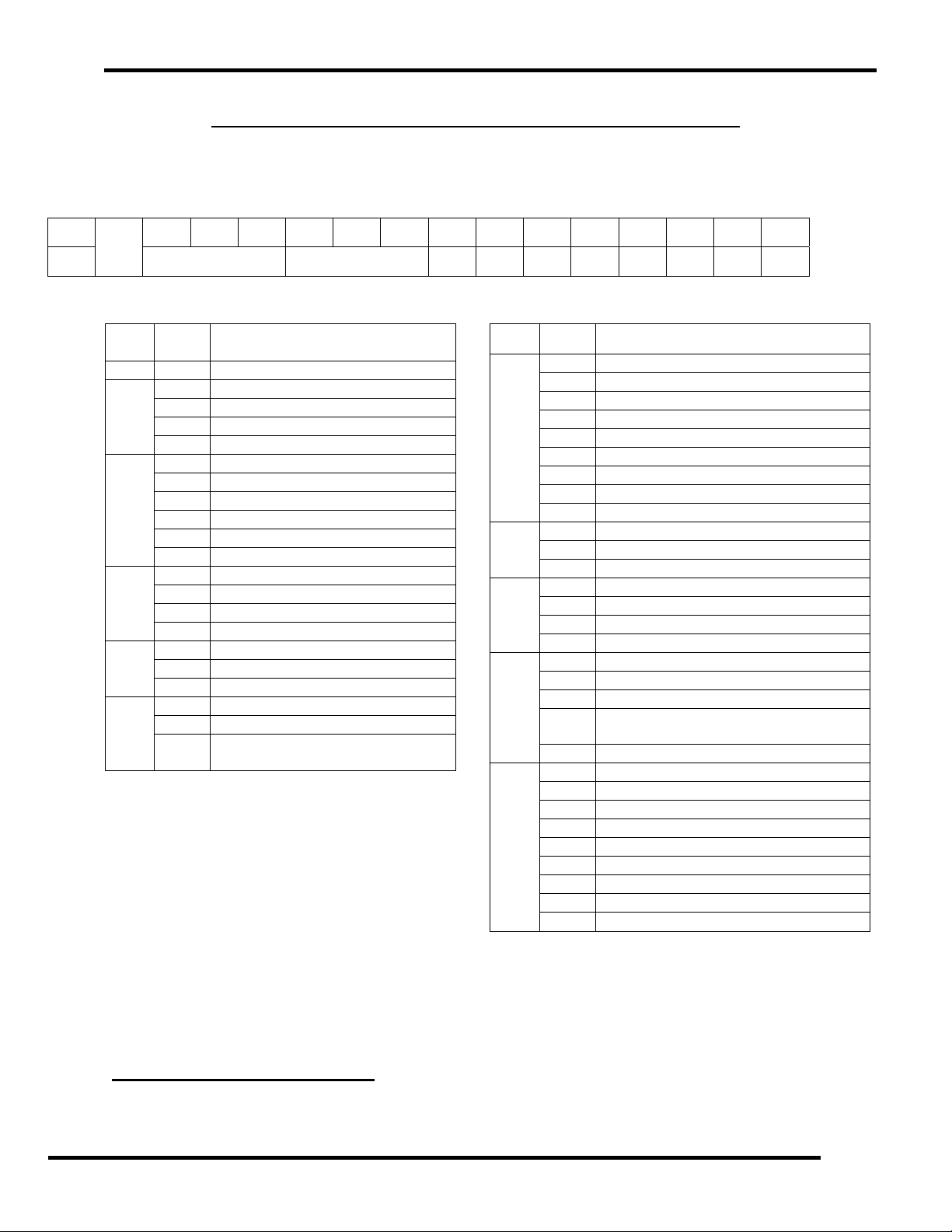
HOW TO READ THE ST MODEL NUMBER CONFIGURATION
The model number describes the options on the charger. Write the model number from the charger ratings specification label
in the spaces provided below. The descriptions shown below will confirm your charger’s configuration. If the charger options
are changed in the field, please make sure to tag the charger with a detailed description of the changes.
ST
A
If a space has no option selected, a zero must be inserted.
Box ST Description
A
B
C
D
E
F
Note:
* 130 Vdc; 50 Adc is not available in 120 Vac.
SAVE THIS MANUAL: Keep it in a location where it is available to anyone who may operate
B C D E F G H I J K
Box ST Description
1 1 Phase
Nominal DC Output Voltage
024 24 Vdc
048 48 Vdc
130 130 Vdc
Nominal DC Output Current
006 6 Adc
012 12 Adc
020 20 Adc
025 25 Adc
050 50 Adc *
Input Voltage
1 120
2 208 (not UL listed)
3 240
Filtering
0 Unfiltered
1 Filtered / Eliminator
Relays
0 No Relays
1 Individual Alarm Relay Contact
Board
or service the charger.
G
H
I
J
K
Remote Sensing
0 Not Supplied
1 Remote Control Panel
2 Remote Temperature Compensation
3 Remote DC Voltage Sensing
4 Lines 1 & 2
5 Lines 1 & 3
6 Lines 2 & 3
7 Lines 1, 2 & 3
Lightning Arrester
0 Not Supplied
1 Included
Charging
0 Not Supplied
1 Parallel Charging
2 Series Charging (Consult Factory)
Special Treatments
0 None
1 Fungus Proofing
2 Conformal Seal On Electronic PC
Board
3 Lines 1 & 2
Other Options
0 None
1 Lockable enclosure door
2 NEMA 4 enclosure
3 NEMA 12 enclosure
4 19” Rack flanges @ 6.0” from front
5 23” Rack flanges @ 6.0” from front
6 Lines 1 & 4
7 Lines 1 & 5
Preliminary Operating Instructions 3 of 62 AIP SERVICE NUMBER 1-800-863-3364
Page 4

TABLE OF CONTENTS
HOW TO READ THE ST MODEL NUMBER CONFIGURATION ....................................................................... 3
TABLE OF CONTENTS....................................................................................................................................... 4
IMPORTANT SAFETY INSTRUCTIONS............................................................................................................. 7
1. INTRODUCTION .............................................................................................................................................. 9
2. RECEIVING CHARGER................................................................................................................................... 9
3. STORING CHARGER...................................................................................................................................... 9
4. LOCATION FOR CHARGER INSTALLATION................................................................................................ 9
FIGURE 4.0: TABLE OF CHARGER ENCLOSURE SIZES.............................................................. 10
5. INSTALLATION OF CHARGER.................................................................................................................... 10
5.1 SHELF, COUNTERTOP OR FLOOR MOUNTING ............................................................................... 10
FIGURE 5.1: BOTTOM MOUNTING HOLE DIMENSIONS............................................................... 11
5.2 WALL MOUNTING ................................................................................................................................ 11
FIGURE 5.2-1: KEYHOLE DIMENSIONS.......................................................................................... 11
FIGURE 5.2-2: CHARGER WALL MOUNTING HOLES................................................................... 11
FIGURE 5.2-3: WALL ANCHOR DESIGN LOADS TABLE.............................................................. 12
5.3 RACK MOUNTING ................................................................................................................................ 12
FIGURE 5.3: ATTACHING RACK-MOUNTING BRACKETS............................................................ 12
6. AC ELECTRICAL SUPPLY ........................................................................................................................... 13
6.1 AC INPUT CONNECTIONS................................................................................................................... 13
FIGURE 6.1-1: RATINGS AND BREAKERS TABLE........................................................................ 13
FIGURE 6.1-2: AC AND DC WIRE HOOK UP................................................................................... 15
FIGURE 6.1-3: GROUND WIRE HOOK UP....................................................................................... 15
6.2 AC VOLTAGE JUMPER SETTINGS..................................................................................................... 15
FIGURE 6.2: AC VOLTAGE JUMPER POSITIONS.......................................................................... 16
6.3 AC AND DC CONNECTION LOCATIONS ........................................................................................... 16
FIGURE 6.3-1: S1 ENCLOSURE...................................................................................................... 16
FIGURE 6.3-2: S2 ENCLOSURE...................................................................................................... 17
FIGURE 6.3-3: S3 ENCLOSURE...................................................................................................... 18
7. DC OUTPUT................................................................................................................................................... 19
7.1 DC OUTPUT CONNECTIONS............................................................................................................... 19
FIGURE 7.1: VOLTAGE DROP PER 1 FT (305MM) OF WIRE TABLE ........................................... 19
8. REMOTE AND ALARM I/O RELAY OPTIONS............................................................................................. 19
8.1 REMOTE DC VOLTAGE SENSING...................................................................................................... 19
8.1.1 WIRING THE REMOTE DC VOLTAGE CABLE............................................................................. 20
FIGURE 8.1.1: CHARGER VOLTAGE SENSING WIRING DIAGRAM ............................................ 20
8.1.2 REMOVING REMOTE VOLTAGE SENSING CABLE.................................................................... 20
8.2 REMOTE TEMPERATURE SENSING CABLE..................................................................................... 20
8.2.1 REMOTE TEMPERATURE SENSING CABLE INSTALLATION................................................... 21
8.2.2 REMOVING TEMPERATURE SENSING CABLE.......................................................................... 21
8.3 OPTIONAL REMOTE CONTROL PANEL............................................................................................ 21
8.3.1 REMOTE CONTROL PANEL INSTALLATION.............................................................................. 21
8.4 ALARM I/O RELAY BOARD OUTPUT................................................................................................. 22
8.4.1 ALARM I/O RELAY BOARD OPERATION.................................................................................... 22
8.4.2 ALARM I/O FIELD INSTALLATION INSTRUCTIONS................................................................... 23
Preliminary Operating Instructions 4 of 62 AIP SERVICE NUMBER 1-800-863-3364
Page 5

8.4.3 WIRING THE ALARM I/O BOARD TO EXTERNAL CIRCUITS..................................................... 23
8.4.4 TESTING THE ALARM I/O RELAY BOARD AND EXTERNAL CIRCUITS .................................. 23
FIGURE 8.4.4-1: ALARM I/O RELAY BOARD MOUNTING............................................................. 24
FIGURE 8.4.4-2: ALARM I/O RELAY BOARD OUTPUT CONNECTIONS...................................... 24
9. CHARGER START UP SEQUENCE............................................................................................................. 25
9.1 CHECK DISPLAY AND LEDS .............................................................................................................. 25
9.2 CHARGER SETTINGS.......................................................................................................................... 25
9.3 AC & DC POWER UP............................................................................................................................ 25
9.4 RECONNECT DC & RE-CHECK........................................................................................................... 25
10. CIRCUIT BOARDS....................................................................................................................................... 25
10.1 SCR DRIVER BOARD......................................................................................................................... 25
FIGURE 10.1: SCR DRIVER BOARD................................................................................................ 26
10.1.1 BACKUP CHARGER POWER...................................................................................................... 26
10.1.2 SUMMARY ALARM BUZZER AND RELAY CONTACT CONNECTIONS.................................. 26
10.1.3 GFI JUMPER................................................................................................................................. 27
10.1.4 INTERNAL TEMPERATURE SENSOR........................................................................................ 27
10.1.5 OPTIONAL REMOTE TEMPERATURE SENSOR CONNECTOR............................................... 27
10.2 CONTROL BOARD FEATURES......................................................................................................... 27
FIGURE 10.2: CONTROL BOARD .................................................................................................... 27
10.2.1 LIQUID CRYSTAL DISPLAY (LCD)............................................................................................. 28
10.2.2 “HOLD TO EQUALIZE” BUTTON (LARGE SQUARE BUTTON)............................................... 28
10.2.3 ARROW BUTTONS....................................................................................................................... 28
10.2.4 GREEN “AC ON” LED.................................................................................................................. 28
10.2.5 GREEN “DC ON” LED.................................................................................................................. 28
10.2.6 YELLOW “FLOAT” LED............................................................................................................... 28
10.2.7 RED “EQUALIZE” LED ................................................................................................................ 28
10.2.8 BUTTON LOCKOUT JUMPER CONNECTOR............................................................................. 28
10.2.9 BEEPER ........................................................................................................................................ 28
11. CONTROL BOARD OPERATION ............................................................................................................... 28
11.1 DEFAULT DISPLAY MODES.............................................................................................................. 28
11.2 HOW TO VIEW OR CHANGE INFORMATION................................................................................... 29
11.3 CHARGER INFORMATION AND MENU DESCRIPTIONS................................................................ 30
11.3.1 DC VOLTAGE AND DC CURRENT.............................................................................................. 30
11.3.2 FAULT CODES AND FAULT LEDS............................................................................................. 30
11.3.3 DC SETTINGS............................................................................................................................... 32
11.3.4 ALARM SETTINGS....................................................................................................................... 33
11.3.5 EQLZ SETTINGS (EQUALIZE SETTINGS).................................................................................. 35
11.3.6 HRS RUN (HOURS RUN) ............................................................................................................. 36
11.3.7 INTEMP (INTERNAL TEMPERATURE)....................................................................................... 36
11.3.8 EXTEMP (EXTERNAL TEMPERATURE)..................................................................................... 36
11.3.9 CURRENT TIME............................................................................................................................ 36
11.3.10 PAUSE (CHARGER PAUSE) ..................................................................................................... 36
11.3.11 NEXT EQLZ (NEXT EQUALIZE CYCLE)................................................................................... 36
12. SPECIAL MENUS........................................................................................................................................ 36
12.1 SECURITY MENU ............................................................................................................................... 36
12.2 TECH MENU........................................................................................................................................ 37
12.2.1 RELAY START.............................................................................................................................. 37
12.2.2 LEDS ARE OFF............................................................................................................................. 37
12.2.3 DISP (DISPLAY VOLTAGE MODE)............................................................................................. 37
Preliminary Operating Instructions 5 of 62 AIP SERVICE NUMBER 1-800-863-3364
Page 6

13. CHARGER CONTROL BOARD QUICK GUIDE ......................................................................................... 37
14. MAINTENANCE........................................................................................................................................... 39
14.1 FUNCTIONAL TESTS......................................................................................................................... 39
14.2 PHYSICAL CLEANING....................................................................................................................... 39
14.3 CHECK AREA AROUND CHARGER................................................................................................. 40
14.4 VISUAL INSPECTION......................................................................................................................... 40
14.5 BATTERY CONDITION....................................................................................................................... 40
15. SERVICING THE CHARGER ...................................................................................................................... 40
15.1 TROUBLESHOOTING......................................................................................................................... 42
15.2 TESTING SCRS................................................................................................................................... 48
15.2.1 SCR1 SHORTED OR LEAKY....................................................................................................... 48
15.2.2 SCR1 OPEN .................................................................................................................................. 48
FIGURE 15.2.2-1: SCR1 TERMINAL DIAGRAM .............................................................................. 49
FIGURE 15.2.2-2: SCR1 TERMINAL DIAGRAM FOR 50A CHARGER........................................... 49
15.3 TRANSFORMER TESTING................................................................................................................. 50
FIGURE 15.3: TRANSFORMER AC VOLTAGES TABLE................................................................ 50
15.4 CHARGER ID TESTING...................................................................................................................... 51
FIGURE 15.4: TS1 ID TERMINAL STRIP RESISTORS TABLE....................................................... 51
16. ORDERING REPLACEMENT PARTS......................................................................................................... 51
17. FACTORY REPLACEMENT PARTS........................................................................................................... 52
18. CHARGER SCHEMATIC............................................................................................................................. 57
19. CHARGER SPECIFICATIONS .................................................................................................................... 58
Preliminary Operating Instructions 6 of 62 AIP SERVICE NUMBER 1-800-863-3364
Page 7
IMPORTANT SAFETY INSTRUCTIONS
1. SAVE THESE INSTRUCTIONS – This manual contains important safety and operating
instructions.
2. Before using battery charger, read all instructions and cautionary markings on battery
charger, battery, and product using battery.
LOOK FOR THIS SYMBOL TO POINT OUT SAFETY
PRECAUTIONS. IT MEANS: BE ALERT—YOUR SAFETY IS
3.
4.
5.
6.
7.
8.
9.
10.
11.
CAUTION: This charger is factory set to charge only lead-acid type rechargeable
batteries. Other types of batteries may burst causing personal injury and damage.
Before charging any other type of rechargeable battery, change the charger settings as
recommended by that battery manufacturer.
DANGER: TO REDUCE THE RISK OF FIRE OR ELECTRIC SHOCK, CAREFULLY READ
AND FOLLOW THESE IMPORTANT SAFETY AND OPERATING INSTRUCTIONS BEFORE
INSTALLING OR OPERATING THE CHARGER.
INSTRUCTIONS IMPORTANTES CONCERNANT LA SECURITÉ.
DANGER: RISK OF ELECTRIC SHOCK. CAPACITORS STORE HAZARDOUS ENERGY.
DO NOT OPEN DOOR OR REMOVE PANELS UNTIL 5 MINUTES AFTER DISCONNECTING
ALL AC AND DC SUPPLY. THE CAPACITORS WILL HOLD A CHARGE FOR UP TO 5
MINUTES AND CAN CAUSE A SHOCK EVEN IF THE POWER HAS BEEN DISCONNECTED.
DANGER: TURN OFF EXTERNAL AC POWER AND DISCONNECT EXTERNAL DC
VOLTAGE BEFORE SERVICING CHARGER OR BEFORE CONNECTING OR
DISCONNECTING THE BATTERY TO PREVENT ARCING OR BURNING.
DANGER: RISK OF ELECTRIC SHOCK. DO NOT TOUCH UNINSULATED ELECTRICAL
PARTS, EITHER AC OR DC, WHILE THE POWER IS CONNECTED.
DANGER: RISQUE DE CHOCKS ÉLECTRIQUES. NE PAS TOUCHER LES PARTIES
NON ISOLÉES DU CONNECTEUR DE SORTI OU LES BORNES NON ISOLÉES DE
L’ACCUMULATEUR.
DANGER: TO PREVENT ELECTRICAL SHOCK, DO NOT TOUCH EITHER AC OR DC
UNINSULATED PARTS. MAKE SURE ALL ELECTRICAL CONNECTORS ARE IN GOOD
WORKING CONDITION. DO NOT USE CONNECTORS THAT ARE CRACKED, CORRODED
OR DO NOT MAKE ADEQUATE ELECTRICAL CONTACT. USE OF A DAMAGED OR
DEFECTIVE CONNECTOR MAY RESULT IN A RISK OF OVERHEATING OR ELECTRIC
SHOCK.
WARNING: HAZARD OF ELECTRIC SHOCK.
INVOLVED. IF YOU DO NOT FOLLOW THESE SAFETY
INSTRUCTIONS, INJURY OR PROPERTY DAMAGE CAN OCCUR.
Preliminary Operating Instructions 7 of 62 AIP SERVICE NUMBER 1-800-863-3364
Page 8

12. Lead-acid batteries generate explosive gases. To prevent arcing or burning near
batteries, do not disconnect DC charging cord from batteries when the charger is
operating. Switch the AC breaker and the DC breaker to the “off” position before
disconnecting the DC output cord from the batteries. Keep sparks, flame, and smoking
materials away from batteries.
13. Always shield eyes when working near batteries. Do not put wrenches or other metal
objects across battery terminal or battery top. Arcing or explosion of the battery can
result.
14. Batteries produce hydrogen gas, which can explode if ignited. Never smoke, use an open
flame, or create sparks near the battery. Ventilate the area when the battery is charging
in an enclosed place.
15. Lead-acid batteries contain sulfuric acid, which may cause burns. Do not get acid in
eyes, on skin, or clothing. If contact with the eyes occurs, flush immediately with clean
water for 15 minutes and obtain medical attention.
16. Only qualified personnel should program or service this equipment.
17. De-energize all AC and DC power connections before servicing this unit. If injury does
occur, apply standard treatment for electric shock and, if necessary, consult with a
physician.
18.
19.
20.
21. This charger is factory set to charge lead-acid batteries.
22. Do not operate the charger if it has received a sharp blow, been dropped, or otherwise
23. Do not disassemble the charger. Have the charger examined by a factory authorized
24. Make sure the battery system has the properly rated voltage for this charging system.
CAUTION: FOR INDOOR USE ONLY. THIS CHARGER IS NOT DESIGNED FOR
OUTDOOR USE. DO NOT EXPOSE THE CHARGER TO RAIN OR SNOW.
ATTENTION: NE PAS EXPOSER À LA PLUIE.
ATTENTION: UTILISER POUR CHARGER UNIQUEMENT LES ACCUMULATEURS AU
PLOMB À ELECTROLYTE LIQUIDE. D’AUTRES TYPES D’ACCUMULATEURS
POURRAIENT ÉCLATER ET CAUSER DES BLESSURES OU DOMMAGES. LES
CCUMULATEURS AU PLOMB À BOÎTIER ÉTANCHE, Y COMPRISE LES BATTERIES À
ÉLECTROLYTE GÉLIFÎE.
damaged. Have a factory authorized service technician examine and repair as needed.
service technician. Incorrect re-assembly of the charger may result in an explosion,
electric shock, or fire.
SAVE THESE INSTRUCTIONS
Preliminary Operating Instructions 8 of 62 AIP SERVICE NUMBER 1-800-863-3364
Page 9

1. INTRODUCTION
This single-phase battery charger is convection cooled, microprocessor controlled, and SCR regulated. The
charger has an “l-E” profile, which is high rate constant current (start region), and constant voltage (plateau
region). The plateau region is defined by one voltage point (knee) where the start region changes into the
plateau region. This plateau voltage point is called the “Float Voltage” and it is factory set at 2.25 volts per cell
for charging lead acid batteries.
The charger has an equalize feature used to perform an equalize charge of the battery. An equalize charge is
periodically used to change the voltage set point above the normal float voltage. This increases the gassing to
mix the electrolyte in a battery and charge all of the cells to a uniform level. The equalize charge voltage is
factory set to 2.32 volts per cell. Contact your battery manufacturer’s authorized service technician for
information on how often your batteries should be equalized.
CAUTION: This charger is factory set to charge only lead-acid type rechargeable batteries. Other
types of batteries may burst causing personal injury and damage. Before charging any other type of
rechargeable battery, change the charger settings as recommended by that battery manufacturer.
The charger settings can be changed by following the instructions in SECTION 11, “CONTROL BOARD
OPERATION”, of this manual.
2. RECEIVING CHARGER
Unpack the charger and examine it for possible shipping damage. If any damage is found, report it
immediately as a claim to the carrier.
3. STORING CHARGER
When the charger is stored prior to being installed and powered up, it should be stored upright, bolted to the
shipping pallet, and covered by the plastic wrap and shipping carton it was shipped in. This will help protect it
from dust and abrasion. It should be stored in an area where it is not likely to be damaged. Do not stack
anything on top of the charger.
It must be stored indoors in a clean and dry environment where the temperatures will not exceed a range of
32º F to 120ºF (0°C to 49°C).
The charger should not be stored more than two years before it is powered up. If the charger capacitors are
not powered up, they will lose their effectiveness over time and may need to be replaced.
4. LOCATION FOR CHARGER INSTALLATION
WARNING: DO NOT INSTALL THE CHARGER ON OR NEAR COMBUSTIBLES OR EXPLOSIVES.
INSTALL THE CHARGER ON A FIRE RESISTANT FOUNDATION OF STONE, BRICK, CONCRETE OR
GROUNDED METAL.
The charger should be located in a clean, cool, dry and well-ventilated area. To permit ample airflow for
convection cooling, allow 4” (102mm) minimum clearance on both the right and left sides of the charger. Allow
more space for cooling and convenience of service and maintenance if possible. Do not obstruct the airflow
space provided behind and underneath the charger.
Allow 36” (914mm) minimum clear space in front of the charger for ease of operation, maintenance and
service.
WARNING: DO NOT INSTALL THE CHARGER ABOVE OR NEAR THE BATTERIES. The batteries give
off hydrogen gas, which rises upward and can be explosive and also produce acid fumes, which may harm the
charger.
Do not install the charger in an area where conditions may be below freezing, above 105° Fahrenheit (40°C) or
above 95% relative humidity. These extreme temperatures will reduce the current capacity and possibly the
Preliminary Operating Instructions 9 of 62 AIP SERVICE NUMBER 1-800-863-3364
Page 10
service life of the charger. If the charger is to be operated at any of these temperature extremes, contact the
manufacturer to verify it will withstand these conditions, and perform at the needed capacity.
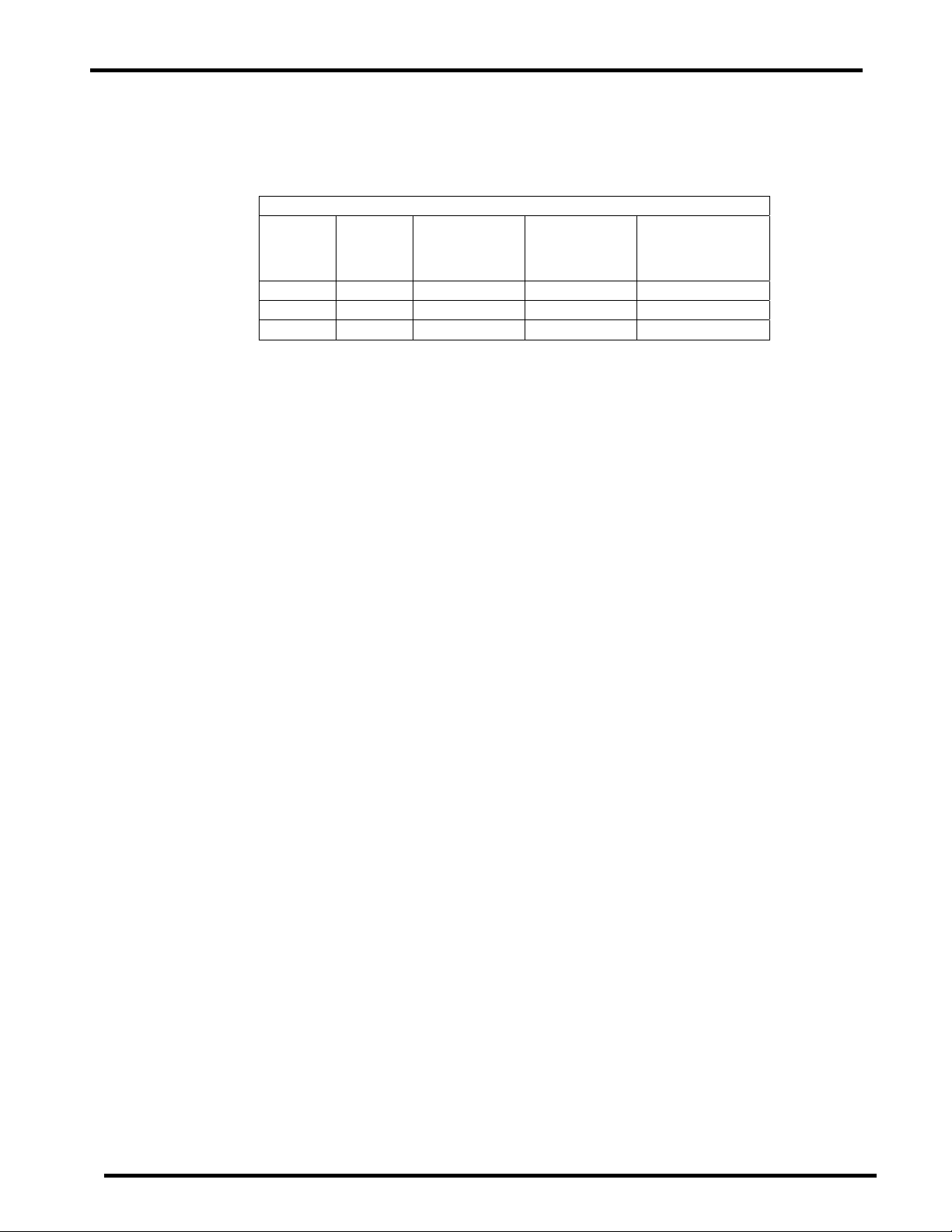
The overall outer dimensions of the S1, S2, and S3 charger enclosures are shown in FIGURE 4.0.
FIGURE 4.0: TABLE OF CHARGER ENCLOSURE SIZES
Overall
Enclosure
sizes
height in
modular
units
Overall height
in inches (mm)
Overall width
in inches (mm)
Overall depth in
inches (mm)
S1 10 U* 17.50 (445) 19.00 (483) 16.75 (425)
S2 15 U* 26.25 (667) 19.00 (483) 16.75 (425)
S3 20 U* 35.00 (889) 19.00 (483) 16.75 (425)
* A modular unit (U) is 1.75” (44mm) as defined by the
ELECTRONIC INDUSTRIES ASSOCIATION (EIA).
** Overall width is from the outer edges of mounting flanges, to correspond to a 19” (483mm) rack width.
5. INSTALLATION OF CHARGER
Proper installation is important to achieve good charger performance and to prevent damage to the charger
and batteries.
The S1, S2, and S3 enclosure sizes of the charger can be mounted on a shelf, countertop, floor, wall, or relay
rack.
Be sure to plan a clear routing for the conduit connections prior to mounting the charger. Looking at the front
of the charger, the conduit knockouts are provided on the right side, left side and bottom of the enclosure. See
SECTION 6.3. The AC input connections should enter at the left and the DC output connections at the right.
The alarm relay wiring, sensor wiring, and remote control wiring should enter at the right side through a
separate conduit knockout from the DC connections. The AC and DC wiring should be separated from each
other and from the other optional types of wiring, this is a UL requirement.
5.1 SHELF, COUNTERTOP OR FLOOR MOUNTING
The S1, S2 and S3 cabinets of the charger are shipped standard with a kit to install four cushioned feet.
These are designed to prevent marring of the mounting surface and to absorb vibration. The kit can be
found inside the charger cabinet in a small plastic bag. The kit consists of four round black rubber feet
and four mounting screws.
To install the feet, carefully lay the charger on its back onto a protective surface such as the shipping
carton collapsed flat. The four small .16” (4mm) diameter mounting holes can be found on the bottom
surface of the charger legs near the four corners of the charger. Place the mounting screw through the
recessed end of the foot. The screw head will be within the recess and the screw point will engage into
the mounting hole in the bottom of the charger. The screw is self-threading into the mounting hole.
Tighten each screw until it is snug but do not over compress the rubber.
Now, the charger can be rotated back to its upright position standing on the rubber feet. Be careful to lift
(do not slide) the charger into position.
Next, to avoid placing strain on the conduit and wiring, anchor the charger so it does not become
displaced. This can be done in either of two ways. The charger can be bolted down to the horizontalmounting surface that it is resting on or it can be bolted to the wall behind it.
To bolt to the horizontal mounting surface, the mounting bolts will attach through the four ½” (13mm)
diameter mounting bolt holes in the bottom surface of the charger legs that are nearest the corners of
the charger. The charger itself can be used as a template to mark the locations of the holes to be made
in the mounting surface or the bottom mounting hole dimensions in FIGURE 5.1 can be used to measure
the locations of the mounting bolt holes.
Preliminary Operating Instructions 10 of 62 AIP SERVICE NUMBER 1-800-863-3364
Page 11
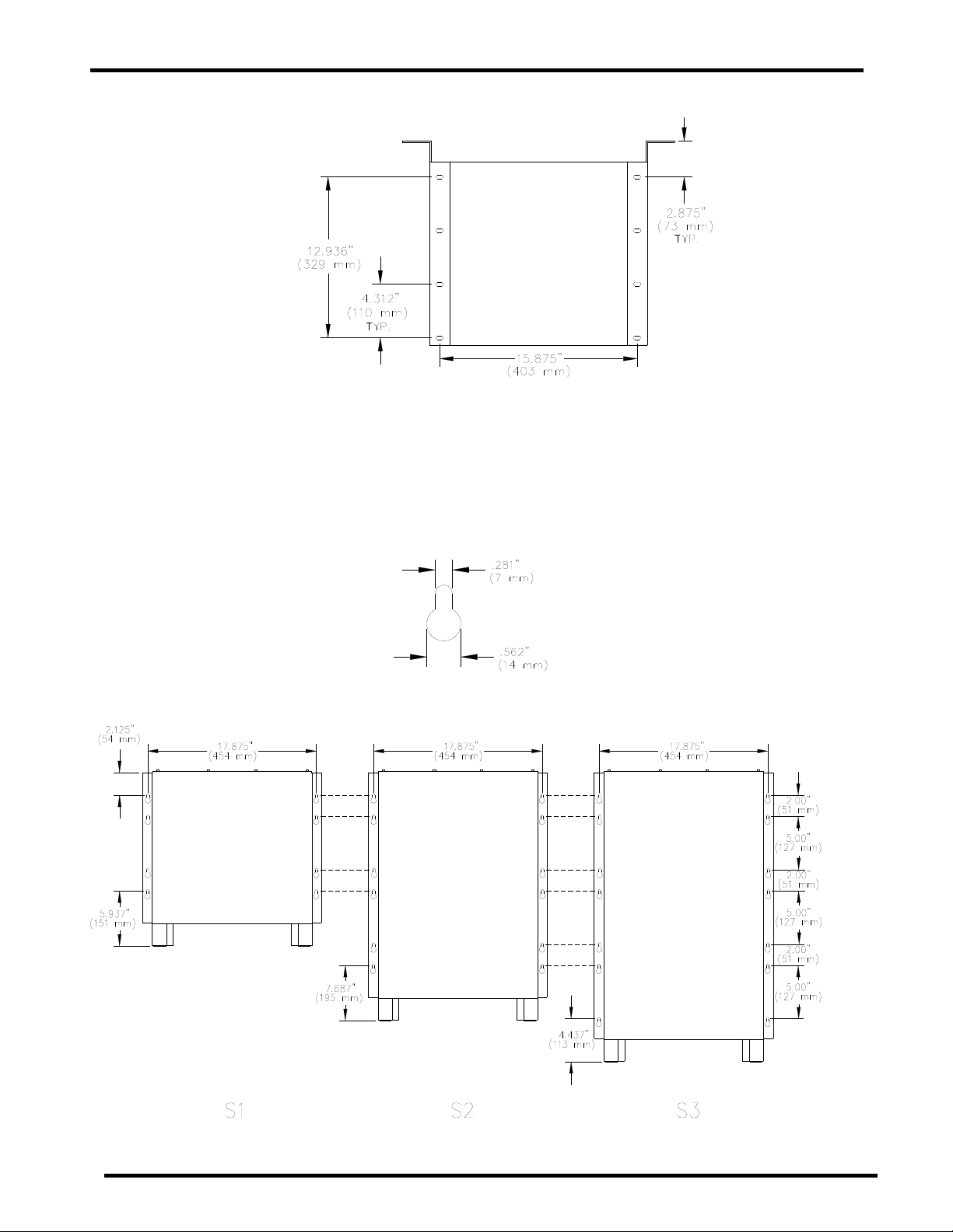
FIGURE 5.1: BOTTOM MOUNTING HOLE DIMENSIONS
5.2 WALL MOUNTING
The S1, S2 and S3 cabinets have built-in wall mounting flanges at the rear. When these flanges are
mounted flush against the wall, they provide for a clear airflow space at the rear of the charger. This
space should not be reduced or obstructed in any way.
The mounting flanges each have a series of keyhole slots. These are designed to conveniently engage
a ¼” (6mm) diameter bolt. The mounting flange bolt hole patterns are shown in FIGURES 5.2-1 and
5.2-2.
FIGURE 5.2-1: KEYHOLE DIMENSIONS
FIGURE 5.2-2: CHARGER WALL MOUNTING HOLES
Preliminary Operating Instructions 11 of 62 AIP SERVICE NUMBER 1-800-863-3364
Page 12
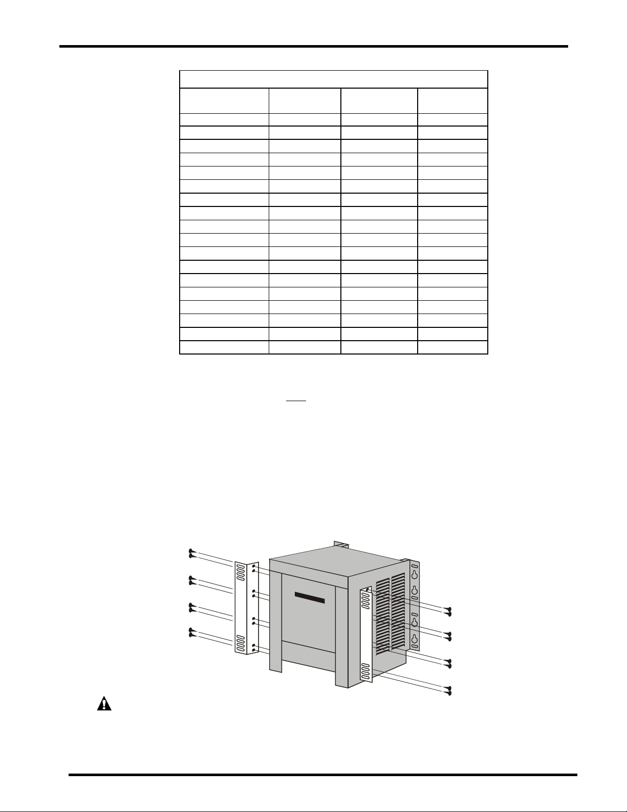
FIGURE 5.2-3: WALL ANCHOR DESIGN LOADS TABLE
Charger Type Enclosure size
Charger weight
lbs. (Kg)
Design load
lbs. (Kg)
24VDC 6A S1 70 (32) 350 (159)
24VDC 12A S1 75 (34) 375 (170)
24VDC 18A S1 85 (39) 425 (193)
24VDC 20A S1 85 (39) 425 (193)
24VDC 25A S1 90 (41) 450 (204)
24VDC 50A S3 190 (86) 950 (432)
48VDC 6A S1 75 (34) 375 (170)
48VDC 12A S1 90 (41) 450 (204)
48VDC 18A S1 110 (50) 550 (249)
48VDC 20A S1 110 (50) 550 (249)
48VDC 25A S1 115 (52) 575 (261)
48VDC 50A S3 222 (100) 1110 (500)
130VDC 6A S1 100 (45) 500 (227)
130VDC 12A S1 130 (59) 650 (295)
130VDC 18A S2 175 (79) 875 (397)
130VDC 20A S2 175 (79) 875 (397)
130VDC 25A S2 190 (86) 950 (432)
130VDC 50A S3 340 (154) 1700 (771)
FIGURE 5.2-3 shows the weight that the set of mounting bolts and their anchoring structure must
withstand for the various charger types. The “DESIGN LOAD” shows the “CHARGER WEIGHT” times a
safety factor of five (5). Be certain that both
the mounting structure and the bolts will, at a minimum,
support the “DESIGN LOAD”. Drywall or plaster will not be strong enough on its own, without proper
structural reinforcement.
5.3 RACK MOUNTING
The S1, S2 and S3 cabinets can be mounted to a standard EIA 19” (483mm) rack system using the
fasteners provided by the rack manufacturer. The rear mounting flanges are configured for an EIA 19”
(483mm) rack for a forward mounting arrangement. For a recessed mounting arrangement, optional
mounting brackets can be attached to the charger sides to fit either an EIA 19” (483mm) or a 23”
(584mm) rack. See FIGURE 5.3.
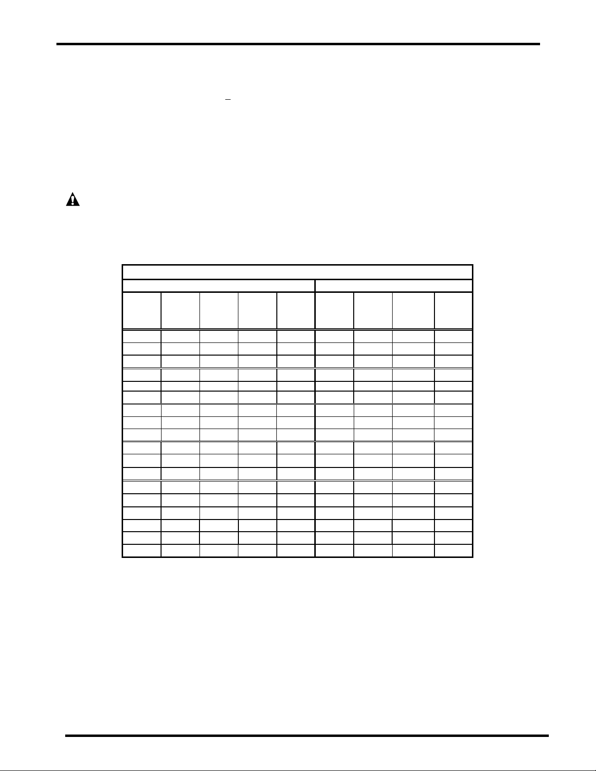
FIGURE 5.3: ATTACHING RACK-MOUNTING BRACKETS
CAUTION: TO ENSURE THE STRUCTURAL INTEGRITY OF THE RACK MOUNTING
BRACKETS, USE THE SIXTEEN #10 SELF-THREADING SCREWS PROVIDED IN THE KIT. USE
EIGHT SCREWS PER BRACKET AND TIGHTEN THEM UNTIL SNUG. DO NOT STRIP THE
THREADS.
Preliminary Operating Instructions 12 of 62 AIP SERVICE NUMBER 1-800-863-3364
Page 13
6. AC ELECTRICAL SUPPLY
The charger must be connected to a single-phase power source. All models can operate on an AC power
source input frequency of 50 or 60 +
3% Hertz. Check the label on the front of the charger or contact the
manufacturer for proper AC power source. The AC input voltage is pre-wired at the factory to 120, 208 or 240
(+10% / -12%) VAC and should not be changed.
NOTE: Field alteration of input voltage voids the charger’s UL Listing.
The AC input wiring must be sized and installed in compliance with the National Electric Code and all
applicable state and local codes and requirements. A qualified electrician must install the AC input wiring
system.
CAUTION: TO REDUCE THE RISK OF FIRE, USE ONLY CIRCUITS PROVIDED WITH BRANCH
CIRCUIT PROTECTION IN ACCORDANCE WITH THE NATIONAL ELECTRICAL CODE, ANSI/NFPA 70.
6.1 AC INPUT CONNECTIONS
The standard charger is shipped with conduit knockouts and no AC power supply cord. A qualified
electrician must perform this AC input wiring work.
FIGURE 6.1-1: RATINGS AND BREAKERS TABLE
DC Output AC Input
Optional
Rated
DC
Volts
24 6 10 15 14 120 only 5 60 or 50 10
24 6 10 15 14 208 only 3 60 or 50 10
24 6 10 15 14 240 only 3 60 or 50 10
24 12 20 30 12 120 only 7 60 or 50 10
24 12 20 30 12 208 only 5 60 or 50 10
24 12 20 30 12 240 only 5 60 or 50 10
24 18 35 40 8 120 only 10 60 or 50 15
24 18 35 40 8 208 only 6 60 or 50 10
24 18 35 40 8 240 only 6 60 or 50 10
24 20 35 40 8 120 only 12 60 or 50 15
24 20 35 40 8 208 only 7 60 or 50 10
24 20 35 40 8 240 only 7 60 or 50 10
24 25 40 60 8 120 only 14 60 or 50 20
24 25 40 60 8 208 only 8 60 or 50 10
24 25 40 60 8 240 only 8 60 or 50 10
24 50 80 90 6 120 only 24 60 or 50 30
24 50 80 90 6 208 only 15 60 or 50 20
24 50 80 90 6 240 only 15 60 or 50 20
Notes: All input AC circuit breakers are of the “high inrush” type to prevent nuisance tripping during power-up.
Rated
DC
Amps
Rms.
DC
Amps
DC
Circuit
Breaker
Amps
Cable
Size
AWG
(Continued on next page)
Rated
AC Input
Volts
Rated
AC
Amps
AC
Frequency
Hz
AC
Circuit
Breaker
Amps
Preliminary Operating Instructions 13 of 62 AIP SERVICE NUMBER 1-800-863-3364
Page 14
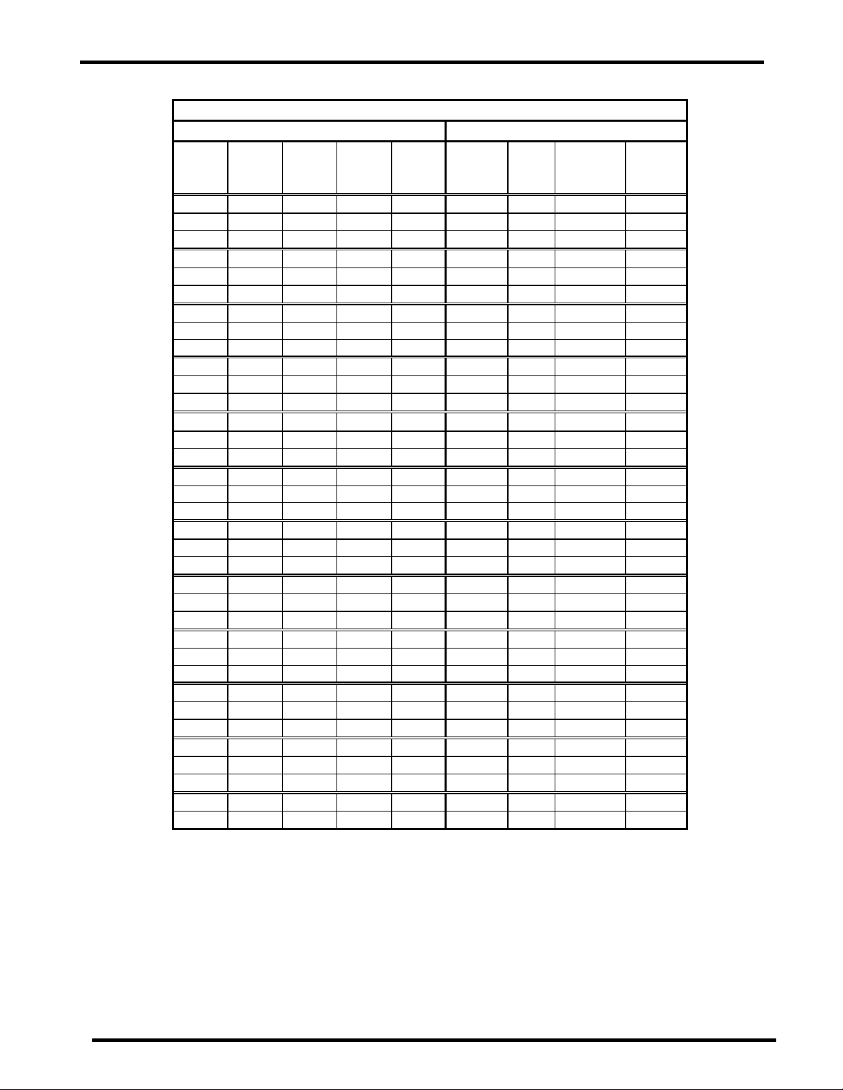
FIGURE 6.1-1: RATINGS AND BREAKERS TABLE
DC output AC input
Rated
DC
Volts
48 6 10 15 14 120 only 7 60 or 50 10
48 6 10 15 14 208 only 5 60 or 50 10
48 6 10 15 14 240 only 5 60 or 50 10
48 12 20 30 12 120 only 14 60 or 50 20
48 12 20 30 12 208 only 8 60 or 50 15
48 12 20 30 12 240 only 7 60 or 50 10
48 18 35 50 8 120 only 17 60 or 50 30
48 18 35 50 8 208 only 11 60 or 50 15
48 18 35 50 8 240 only 10 60 or 50 15
48 20 35 50 8 120 only 18 60 or 50 30
48 20 35 50 8 208 only 12 60 or 50 15
48 20 35 50 8 240 only 10 60 or 50 15
48 25 40 60 8 120 only 28 60 or 50 30
48 25 40 60 8 208 only 14 60 or 50 20
48 25 40 60 8 240 only 13 60 or 50 20
48 50 80 90 6 120 only 45 60 or 50 60
48 50 80 90 6 208 only 25 60 or 50 40
48 50 80 90 6 240 only 23 60 or 50 40
130 6 10 15 14 120 only 14 60 or 50 20
130 6 10 15 14 208 only 9 60 or 50 15
130 6 10 15 14 240 only 8 60 or 50 15
130 12 20 25 12 120 only 27 60 or 50 40
130 12 20 25 12 208 only 17 60 or 50 30
130 12 20 25 12 240 only 15 60 or 50 25
130 18 35 40 8 120 only 45 60 or 50 60
130 18 35 40 8 208 only 24 60 or 50 40
130 18 35 40 8 240 only 21 60 or 50 30
130 20 35 40 8 120 only 45 60 or 50 60
130 20 35 40 8 208 only 24 60 or 50 40
130 20 35 40 8 240 only 22 60 or 50 30
130 25 40 60 8 120 only 63 60 or 50 70
130 25 40 60 8 208 only 32 60 or 50 40
130 25 40 60 8 240 only 32 60 or 50 40
130 50 80 90 4 208 only 70 60 or 50 90
130 50 80 90 4 240 only 60 60 or 50 70
Notes: All input AC circuit breakers are of the “high inrush” type to prevent nuisance tripping during power-up.
Rated
DC
Amps
Rms.
DC
Amps
DC
Circuit
Breaker
Amps
Wiring and connections must meet the requirements of the National Electric Code, state and local codes
and requirements, and the requirements in this manual.
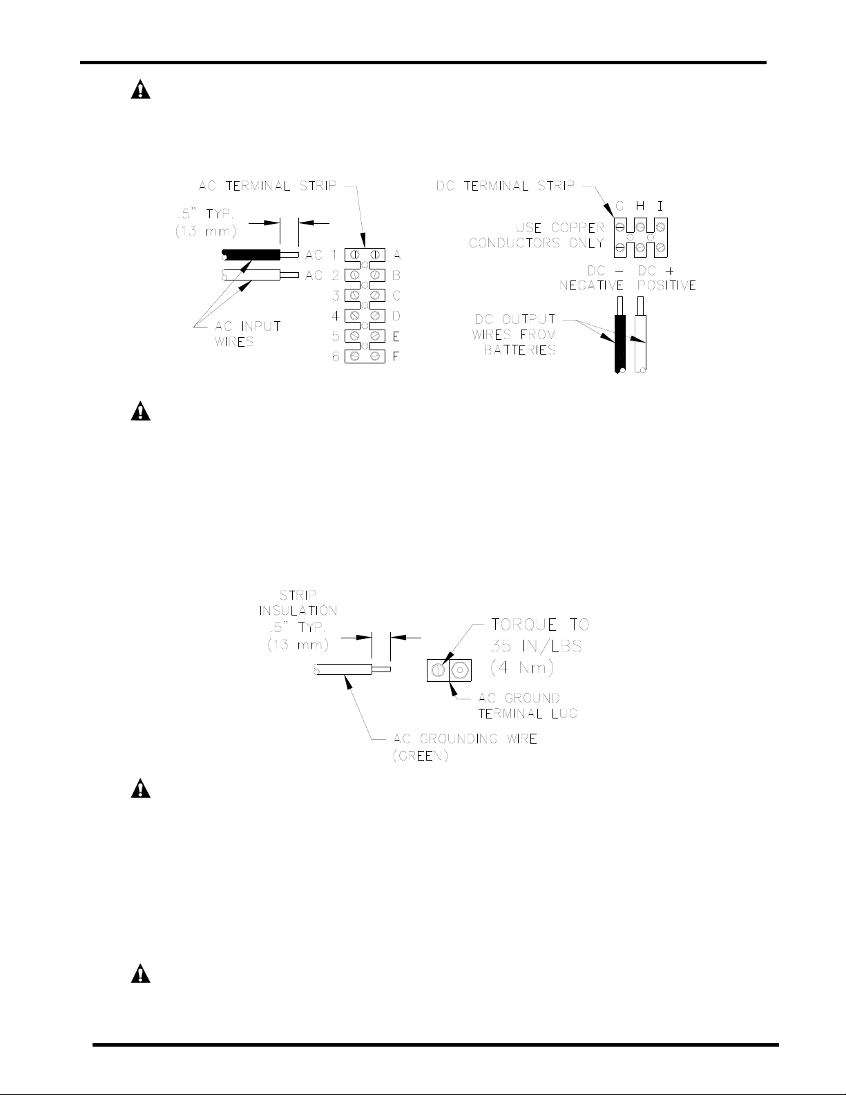
To connect the input AC voltage, route the AC conduit through the appropriate knockout hole. See
SECTION 6.3. Route the AC wiring to terminal lugs AC1 and AC2 located above the AC breaker as
shown in FIGURE 6.1-2. For proper connection, torque the AC1 and AC2 terminal strip screws to
18 inch pounds (2Nm), and the ground lug screw to 35 inch pounds (4Nm), see FIGURES 6.1-2
and 6.1-3.
Optional
Cable
Size
AWG
Rated
AC Input
Volts
Rated
AC
Amps
AC
Frequency
Hz
AC Circuit
Breaker
Amps
Preliminary Operating Instructions 14 of 62 AIP SERVICE NUMBER 1-800-863-3364
Page 15
WARNING: ALL AC AND DC CIRCUIT BREAKERS MUST BE IN THE “OFF” POSITION WH ILE
MAKING THE AC AND DC CONNECTIONS TO THE CHARGER.
FIGURE 6.1-2: AC AND DC WIRE HOOK UP
WARNING: IMPROPERLY CONNECTED WIRING CAN CAUSE AN ELECTRICAL FIRE.
Connect the AC ground to the terminal lug located to the right of the AC breaker on the charger floor as
shown in FIGURE 6.1-3. In some models the AC ground lug is above the AC terminal strip on the innerpanel. See SECTION 6.3. For proper connection torque the screw to 35 inch pounds (4Nm).
FIGURE 6.1-3: GROUND WIRE HOOK UP
(Located on charger floor (S1,S2) or above terminal strip (S3))
WARNING: DO NOT OPERATE THE CHARGER WITHOUT PROPER GROUNDING.
IMPROPER GROUNDING MAY CAUSE AN ELECTRIC SHOCK, WHICH COULD RESULT IN INJURY
OR DEATH.
6.2 AC VOLTAGE JUMPER SETTINGS
Check the “AC VOLTS” box on the charger rating specification label to determine its AC Voltage setting.
The AC Voltage jumper settings and the AC Input Voltage of the charger cannot be changed. See
FIGURE 6.2 for AC Voltage Jumper Settings.
NOTE: Field alteration of AC voltage jumper settings voids charger’s UL listing.
WARNING: IMPROPER AC VOLTAGE JUMPER CONNECTION MAY CAUSE SEVERE
DAMAGE TO THE CHARGER AND BATTERY.
Preliminary Operating Instructions 15 of 62 AIP SERVICE NUMBER 1-800-863-3364
Page 16
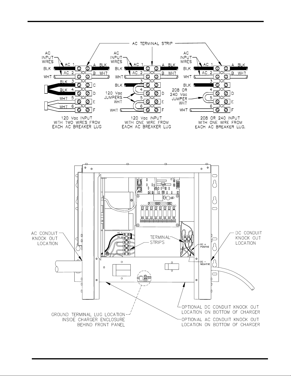
FIGURE 6.2: AC VOLTAGE JUMPER POSITIONS
6.3 AC AND DC CONNECTION LOCATIONS
FIGURE 6.3-1: S1 ENCLOSURE
Preliminary Operating Instructions 16 of 62 AIP SERVICE NUMBER 1-800-863-3364
Page 17
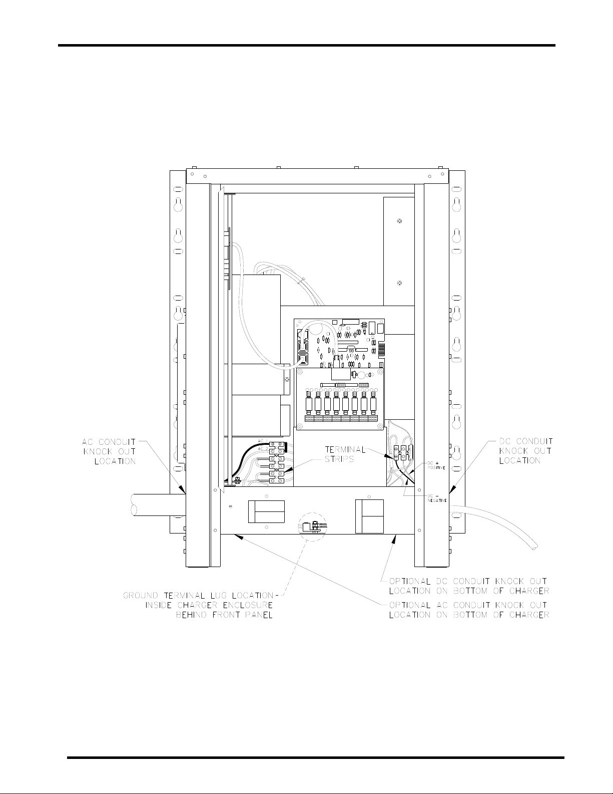
FIGURE 6.3-2: S2 ENCLOSURE
Preliminary Operating Instructions 17 of 62 AIP SERVICE NUMBER 1-800-863-3364
Page 18
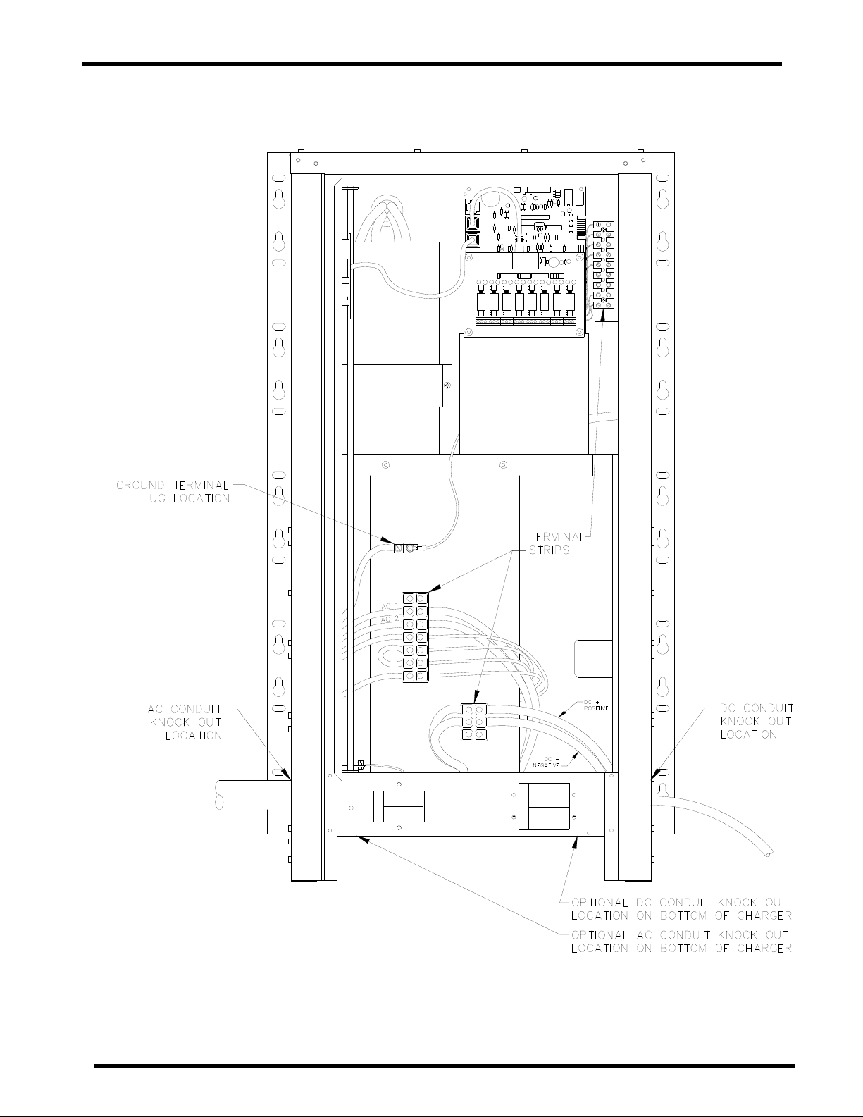
FIGURE 6.3-3: S3 ENCLOSURE
Preliminary Operating Instructions 18 of 62 AIP SERVICE NUMBER 1-800-863-3364
Page 19
7. DC OUTPUT
It is recommended that a DC disconnect switch or circuit breaker be used between the charger and the DC
bus. This device should have lockout capability to allow the charger to be disconnected from the DC bus when
connecting the charger during installation and maintenance.
7.1 DC OUTPUT CONNECTIONS
The standard charger is shipped with conduit knockouts and no DC output cable. Determine which
charger knockout to route the DC output cable through. See Section 6.3. Make sure to keep the DC
output cable isolated from the AC input cables and any other optional wiring.
To help in determining the proper size of cable to use for the DC output, FIGURE 7.1 lists the DC voltage
drop per one foot (305mm) of cable for the various Rated DC currents of the chargers and various wire
sizes. Take the appropriate number from FIGURE 7.1, and multiply it by the cable length needed to get
the approximate voltage drop from the charger to the battery or DC bus. FIGURE 7.1 values are
approximate values, the exact value can be measured after installation.
NOTE: If the total voltage drop of the DC output cable is greater than 1% of the charger voltage ( 0.24
VDC for a 24 VDC system, 0.48 VDC for a 48 VDC system, 1.3 VDC for a 130 VDC system) it is
recommended that the optional Remote DC Voltage Sensing cable be used.
To connect the DC output cable, route the conduit through the appropriate knockout hole. Route the DC
positive wire to terminal lug labeled DC POSITIVE and the DC negative wire to terminal lug labeled DC
NEGATIVE located above the DC breaker as shown in FIGURE 6.1-2. For proper connection, torque
the terminal strip screws to 18 inch pounds (2Nm). The charger will not operate in a reversed polarity
condition. The DC output circuit breaker is used to protect the silicon-controlled rectifiers (SCRs).
NOTE: DC circuit breaker may trip when switched on until capacitors are charged.
FIGURE 7.1: VOLTAGE DROP PER 1 FT (305mm) OF WIRE TABLE
For stranded copper wire at 68°F (20°C)
WIRE
SIZE
(AWG.)
16 0.0450 0.0900
14 0.0270 0.0540
12 0.0180 0.0360
10 0.0110 0.0220
8 0.0070 0.0140
6 0.0045 0.0090
4 0.0025 0.0050
2 0.0018 0.0036
1 0.0015 0.0030
0 0.0011 0.0022
6A 12A
RATED DC CURRENT, AMPERES
18A
0.1440
0.0864
0.0576
0.0352
0.0224
0.0144
0.0080
0.0058
0.0048
0.0035
20A 25A 50A
- - -
0.0945 - -
0.0630 0.0720 -
0.0385 0.0440 0.0880
0.0245 0.0280 0.0560
0.0158 0.0180 0.0360
0.0088 0.0100 0.0200
0.0063 0.0072 0.0144
0.0053 0.0060 0.0120
0.0039 0.0044 0.0088
8. REMOTE AND ALARM I/O RELAY OPTIONS
The Remote option allows the charger to be controlled and monitored remotely. The ALARM I/O relay board
allows the user to connect other devices to it to monitor various faults. The following sections go over function
and installation of these optional parts.
8.1 REMOTE DC VOLTAGE SENSING
This option will compensate for the voltage drop across the DC output cable due to the resistance and
current flowing through it. The remote voltage sensing cable can measure the DC voltage of batteries or
DC bus up to 30 ft. (9m) with the standard cable length. This can be extended with a longer cable. This
gives the charger display a more accurate voltage display. In order for the charger to function, the
connection to the DC bus must be secure and reliable.
Preliminary Operating Instructions 19 of 62 AIP SERVICE NUMBER 1-800-863-3364
Page 20

If the charger was shipped from the factory with the optional Remote Voltage Sensing cable, it will have
the sensing wires installed into the correct terminal strip and have the resistors moved to the correct
location. If this option is added later, installation instructions on how to wire it will be included.
8.1.1 WIRING THE REMOTE DC VOLTAGE CABLE
With both AC and DC de-energized follow the procedure below:
1. Place the RED and BLACK wires that are coiled up inside the charger through one of the spare
knockouts provided on the DC side of the enclosure. See SECTION 6.3. Do not place in the
same knockout as either the AC input or DC output wiring. Protect the wires to ensure the sharp
edges of the opening will not damage the wire. It is recommended to place a fuse in-line with the
cable near the battery connection in case the wires would get shorted together.
2. Securely con nect the RED wire to the POSITIVE of the battery or DC bus.
3. Securely con nect the BLACK wire to the NEGATIVE of the battery or DC bus.
4. Wire tie the cables so they can not be pulled loose.
5. After the charger is fully installed, connect the DC bus to the charger. Verify the voltage on the
display corresponds to the actual battery voltage. If so, the charger is ready for service.
For wiring diagram of this option, see FIGURE 8.1.1.
FIGURE 8.1.1: CHARGER VOLTAGE SENSING WIRING DIAGRAM
Torque all connections to 9 inch pounds (1Nm).
8.1.2 REMOVING REMOTE VOLTAGE SENSING CABLE
When removing Remote Voltage Sensing Cable both AC and DC will need to be de-energized.
Reference FIGURE 8.1.1 for proper placement of wires and R3 resistors.
8.2 REMOTE TEMPERATURE SENSING CABLE
This option will allow the charger to adjust the charging voltage to compensate for the temperature of the
batteries. The temperature of the battery will be closely monitored by the sensor and the float and
equalize voltages will be adjusted accordingly. The remote temperature sensing cable has a
temperature sensor that needs to be mounted to the battery post for accurate battery temperature
sensing.
Temperature compensation is based on a reference temperature of 77°F (25°C). The Temperature
compensation factor is - 2.5 mV (millivolts) per Cell per Degree F (- 4.5 mV per cell per Degree C). The
compensation factor is NEGATIVE because of the inverse relationship between the temperature and the
voltage (i.e. as the temperature increases the voltage should decrease).
Preliminary Operating Instructions 20 of 62 AIP SERVICE NUMBER 1-800-863-3364
Page 21

Note: When the remote temperature sensing cable is not installed, charging voltages can be
adjusted to compensate based on the internal temperature sensor, which is inside each charger
on the SCR driver board.
8.2.1 REMOTE TEMPERATURE SENSING CABLE INSTALLATION
A charger shipped from the factory will not have this option connected and temperature
compensation will be disabled. With both AC and DC de-energized, follow the procedure below:
1. The remote temperature sensing cable will be in the charger’s shipping carton. Carefully
unpack the cable from its bag and inspect for any cuts in the cable.
2. Place the 3-pin connector of the cable through one of the spare knockouts provided on the
DC side of the enclosure. See SECTION 6.3. Do not place in the same knockout as either
the AC input or DC output wiring. Protect the wire to prevent damage from the sharp edges
of the opening.
3. Connect the 3-pin connector to JP5. Secure the cable to prevent it from being pulled loose.
See FIGURE 10.1.
4. Secure the other end of the cable to a negative battery terminal post in the center of the
battery set.
5. After the installation is finished, connect DC voltage and verify that the display temperature
corresponds to the temperature of the battery. To view the external temperature, refer to
SECTION 11.3.8 of the manual.
6. Enable the Temperature Compensation by going to DC Settings then go to Temperature
Compensation. Default is disabled. Enable it to External (EX) by pressing right twice, refer
to SECTION 11.3.3 of the manual.
7. The charger is ready for service if the charger display shows the proper battery temperature.
8.2.2 REMOVING TEMPERATURE SENSING CABLE
With both AC and DC de-energized, remove connector from JP5. The charger will automatically
detect that there is no external temperature cable and return to temperature compensation
disabled.
8.3 OPTIONAL REMOTE CONTROL PANEL
This option will allow the charger to be controlled remotely from a distance of up to 50-ft. (15m); without
this option the charger would be controlled from the front door panel. Only one control panel can be
connected at a time. The Remote Control Panel is shipped with a 50-ft. (15m) communication cable with
plug-in connectors. The Remote Control Panel can be mounted to a 19-in. (483mm) relay rack or wall
mounted.
8.3.1 REMOTE CONTROL PANEL INSTALLATION
With both AC and DC de-energized, follow the procedure below:
1. If the Remote Control Panel was ordered with the charger as an option, it will be found
packed inside of the carton shipped with the charger. If it was ordered separately as a
service part kit, it will be packaged in its own carton. In either case, carefully unpack the
control panel assembly and inspect for any cuts in the cable or other damage.
2. It will be necessary to connect the remote control panel printed circuit board to the SCR
driver printed circuit board in the charger. If the remote control panel was ordered as a
service part option and the charger has a control board on the door then the Control printed
circuit board on the door will have to be disconnected before installing the Remote Control
Panel. Only one control printed circuit board can be electrically connected to the SCR Driver
board at a time.
3. Determine where and how the Remote Control Panel will be mounted. The Control Panel is
shipped from the factory with the communication cable entering the bottom of the case. If
preferred by the installer, the cable can be changed to enter the back of the case.
4. To change where the cable enters, remove the four nuts on the case cover to open the case.
Disconnect the cable from the control board, being careful to squeeze the retaining latch on
the cable connector before pulling on the connector. If the latch has been properly released,
Preliminary Operating Instructions 21 of 62 AIP SERVICE NUMBER 1-800-863-3364
Page 22

the connector will easily slide out of the socket. Carefully pull the cord and connector out
through the hole in the bottom of the cover. Reinstall the cable through the backside of the
larger hole in the back panel of the case. Reconnect the cable to either one of the connector
sockets on the control printed circuit board. Re-assemble the Remote Control Panel.
5. Carefully route the 50 ft. (15m) long communication cable to the charger making sure it is
protected from being pulled out of the Remote Control Panel or pinched.
6. Place the cable through one of the spare knockouts provided on the DC side of the
enclosure. See SECTION 6.3. Do not place in the same knockout as either the AC input or
DC output wiring. Protect the cable to ensure that the sharp edges of the knockout opening
will not damage the cable. Any excess communication cable can be coiled up and wire tied
out of the way.
7. The communication cable can be connected into any of the three RJ1, RJ2 or RJ3 connector
sockets on the charger SCR driver board. Do not connect more than one control board to the
SCR Driver board at the same time.
8. Reconnect the charger to either AC or DC and then verify that the Remote Control Panel is
functioning properly, (refer to SECTION 11). If both charger and remote control panel are
operating normally, they are ready for service.
Important: Proprietary communication protocol is used with the charger and control panel.
Equipment damage will occur if they are connected to Ethernet or any other network device or
port.
8.4 ALARM I/O RELAY BOARD OUTPUT
The optional ALARM I/O Relay board allows the user the use of “NO” (normally open) or “NC” (normally
closed) contacts with reference to “C” (common) to be connected to other equipment for fault detection.
The one GREEN LED and seven RED LEDs are used to signify when each individual relay coil has been
energized. The ALARM I/O Relay board receives its signal to energize the relays from the Charger
Control board.
8.4.1 ALARM I/O RELAY BOARD OPERATION
The GREEN LED (DS1) and J1 contacts are used to indicate the Auxiliary Summary Alarm fault
status. (See FIGURE 8.4.4-2) The GREEN LED will illuminate if the charger detects no faults.
Thirty seconds after any of the monitored faults have occurred, the J1 relay coil will be deenergized and the GREEN LED will go off.
C=COMMON NC=NORMALLY CLOSED NO=NORMALLY OPEN
The J1 terminal block contacts on the ALARM I/O relay board will switch at the same time as the
Summary Alarm terminal block contacts on the SCR Driver Board. With no faults the relay will be
energized and there will be continuity from “C” to “NC” and no continuity from “C” to “NO” on J1.
With a fault the relay coil will be de-energized and there will be continuity from “C” to “NO” and no
continuity from “C” to “NC”.
The seven RED LEDs and the J2 through J8 terminal block contacts on the ALARM I/O board are
used to indicate the seven individual fault conditions. Each relay will be energized and its
corresponding LED will illuminate when the SCR Driver board detects that fault. When there are
no faults, the relays will be de-energized and there will be continuity from “C” to “NC” and there
will be no continuity from “C” to “NO” on J2 through J8. With a fault, the appropriate relay coil will
be energized and there will be continuity from “C” to “NO” and no continuity from “C” to “NC”. The
appropriate LEDs will illuminate with each fault. See SECTION 11.3.4 for information on setting
up the charger faults. The ALARM I/O relay board terminal blocks and LED indicated fault
functions are shown in FIGURE 8.4.4-2.
Preliminary Operating Instructions 22 of 62 AIP SERVICE NUMBER 1-800-863-3364
Page 23

8.4.2 ALARM I/O FIELD INSTALLATION INSTRUCTIONS
The installation kit will come with the following components:
Qty. Part # Description
1 22845-XX* ALARM I/O Relay Board
1 31666 1 ft. (305mm) Communication cable
1 33456 Wiring Shield
4 32678 Spacers
4 03237 Nuts, 6-32
* - XX-Multiple options available, see SECTION 17 for proper option number.
Follow the instructions below to install the ALARM I/O Relay Board into the charger:
1. De-energize both AC and DC power from the charger.
2. To see how the ALARM I/O Relay board mounts to the SCR Driver Board and the cable
hookup, see FIGURE 8.4.4-1. (All RJ45 connector sockets are in parallel, so it will work with
the cable in any location.)
3. Install the four nylon spacers into the SCR Driver board on the inner panel of the charger.
4. Put the wiring shield on the bottom two nylon spacers.
5. Mount the ALARM I/O Relay board o n the four nylon spa ce rs a s shown.
6. Install the four nuts on the nylon spacers and tighten. (Do not over-tighten nuts or the nylon
spacers will strip.)
7. Connect the communication cable from the SCR Driver board RJ45 connector socket to the
ALARM I/O Relay board RJ45 connector socket.
8. Fold the wiring shield under the front of the charger base edge by the circuit breaker if
possible.
8.4.3 WIRING THE ALARM I/O BOARD TO EXTERNAL CIRCUITS
1. Route the wiring for your external circuits into the charger through one of the spare conduit
knockouts on the DC side of the enclosure. See SECTION 6.3. Make sure to isolate this
wiring from the charger AC input and DC output power wiring. The wiring shield is to help
isolate these wires from the other wires. Do not place in the same knockout as either the AC
input or DC output wiring.
2. Use #26-14 AWG wire stripped 0.25 in. (6mm) on the end going into the Individual Alarm
Terminal Blocks. Torque all connections to 5 inch pounds (.6Nm). All terminal blocks are
labeled in the non-alarm or fault condition.
3. Make sure to observe the Alarm Relay Contact Rating on FIGURE 8.4.4-2 when wiring into
external circuits.
4. Secure all wires with a strain relief in the conduit knockout so they will not to be pulled out of
unit. Protect the wires to ensure the sharp edges of the opening will not damage the wire.
5. Return power to the charge r.
8.4.4 TESTING THE ALARM I/O RELAY BOARD AND EXTERNAL CIRCUITS
1. It is recommended that a test be performed after installation to make sure everything works
as intended.
2. Go into the TEC H MENU on the charge r control board by pressing the RIGHT ARROW, then
LEFT ARROW buttons, and repeat this sequence 4 times while in the default display mode,
then enter the TECH MENU code which is set to “0001”. (For additional information on the
TECH MENU see SECTION 12.2.)
3. The first display in the TECH MENU is the control board version and date.
4. Press the DOWN ARROW button and you can get to the following menus: Relay Start, LEDs
are off, and Disp (Display voltage mode).
5. Go to the Relay Start Menu. This menu will only be available if the charger has an optional
ALARM I/O Relay Board that is functioning.
6. Press the RIGHT ARROW button at the “Relay Start” display. The ALARM I/O Relay Board
LEDs and Relay Contacts will go through a test cycle to verify they are working properly.
7. If you press the RIGHT ARROW button while the display shows “Relay Stop”, the test will
stop.
8. You can restart the test anytime the display shows “Relay Start”.
9. To exit the TECH MENU, press the LEFT ARROW button.
10. The charger is ready for service if all of these tests verify that it functions properly.
Preliminary Operating Instructions 23 of 62 AIP SERVICE NUMBER 1-800-863-3364
Page 24

FIGURE 8.4.4-1: ALARM I/O RELAY BOARD MOUNTING
FIGURE 8.4.4-2: ALARM I/O RELAY BOARD OUTPUT CONNECTIONS
Preliminary Operating Instructions 24 of 62 AIP SERVICE NUMBER 1-800-863-3364
Page 25

9. CHARGER START UP SEQUENCE
When all connections are made with the proper wire size, location and torque value, the charger is ready for
power up. Use the following steps to start up the charger.
9.1 CHECK DISPLAY AND LEDS
Switch the charger AC and DC breakers “OFF”, and disconnect the charger from the battery. Then,
reconnect the DC battery bus voltage to the charger. The Display and LEDs on the front of the charger
should power up and display the DC voltage that the charger senses on the DC terminal strip. If the
display does not show the proper DC voltages, disconnect charger from the DC battery bus and verify
connections and polarity again. (The charger requires at least 17 volts DC for the display to power up in
the 24 and 48-volt DC chargers and at least 100 volts DC in the 130-volt DC chargers.) If the Display or
LEDs do not power up correctly, even though connections were verified to be correct, see the
Troubleshooting section. Note: The back light of the LCD display will not be illuminated while the AC
breaker is off.
9.2 CHARGER SETTINGS
If the charger senses the proper voltage, you can go into the charger menus and customize the charger
settings. At this time, the summary alarm buzzer may sound because of various fault codes. If
necessary, disable the alarm buzzer or the fault condition while customizing the charger settings and
then enable them after the charger setup is complete.
9.3 AC & DC POWER UP
Disconnect the charger from the DC battery bus again with the switch or breaker. Apply the proper AC
voltage to the Charger AC terminal strip. Turn the AC Breaker “ON”. The charger Display should power
up with the display back light on, the “AC ON” LED should illuminate, now turn the DC breaker “ON”.
The charger will power up and slowly charge up the capacitor(s) in the charger to the proper float
voltage. The “DC ON” LED will illuminate.
9.4 RECONNECT DC & RE-CHECK
Connect the charger to the DC battery bus again with the switch or breaker. The charger will start
charging the battery at the appropriate voltage and current if everything is functioning properly. If you
experience any problems, go to the Troubleshooting section.
10. CIRCUIT BOARDS
The standard circuit boards are the SCR Driver Board and the Control Board. The optional circuit board is the
ALARM I/O Relay Board. Each of these three boards can be used universally in all charger models.
All three boards have RJ45 connector sockets to allow them to be easily connected or disconnected from each
other for service or to allow the use of an optional Remote Control Panel. The RJ45 connector sockets are all
connected in parallel so the cables can be plugged into any of the RJ45 receptacles on each board.
10.1 SCR DRIVER BOARD
The SCR Driver Board stores all of the important variables for the charger except for the time of an
equalize cycle. It determines what model the charger is, monitors the charger system for faults, and
sends information to the control board. It also provides the SCR gate drive pulses to control the charger
output and the proper supply voltages for the other two boards.
The following features are found on the SCR Driver Board. See FIGURE 10.1 for location of
components.
Preliminary Operating Instructions 25 of 62 AIP SERVICE NUMBER 1-800-863-3364
Page 26

FIGURE 10.1: SCR DRIVER BOARD
10.1.1 BACKUP CHARGER POWER
The SCR Driver Board is normally powered from the AC input power. However, if AC input power
is not present the SCR Driver Board will automatically switch to be powered from the DC batteries
as a backup power source. The SCR Driver Board includes a DC-to-DC converter that allows the
wide range of DC Battery voltage supplies to be converted to a usable 12 volt DC source. The
DC-to-DC converter has a fuse (F2) for over-current protection. This allows the charger to
monitor the charger information and provide the power supplies to the other circuit boards.
NOTE: It will not charge the batteries until AC power has returned.
10.1.2 SUMMARY ALARM BUZZER AND RELAY CONTACT CONNECTIONS
The Summary Alarm and Relay Contact Connections provide the user with two ways to monitor
for faults. See the Alarm Settings menu section for alarm setting information.
The Summary alarm buzzer and contacts will be enabled 30 seconds after the board detects a
fault code, reference FIGURE 10.1. Removing the JP3 jumper connector from pins 1 and 2 of
the JP3 connector can disable the summary alarm buzzer. When the jumper is connecting pins 1
and 2 (bottom two pins) the summary alarm buzzer is enabled. Removing the jumper from pins 1
and 2 disables the alarm buzzer. The jumper can be stored by installing it on pins 2 and 3 (top
two pins). Removing the fault code or disarming the fault code from the charger can be done
from the Alarm Settings Menu.
Preliminary Operating Instructions 26 of 62 AIP SERVICE NUMBER 1-800-863-3364
Page 27

The Summary Relay coil will also be de-energized after the board detects a fault for 30 seconds.
This will change the Relay Contact Connections on the JP2 terminal strip. With a fault the relay
coil will be de-energized and there will be continuity from “C” (common) to “NO” (normally open)
and no continuity from “C” to “NC” (normally closed). With no faults the relay will be energized
and there will be continuity from “C” (common) to “NC” (normally closed) and no continuity from
“C” to “NO” (normally open) on the JP2.
External wiring can be connected to the JP2 terminal block connections for external fault
detection. See SECTION 19 for information about the Alarm relay contact ratings.
10.1.3 GFI JUMPER
The GFI (Ground Fault Indicator) Jumper can be used to Enable (pins 2-3 of JP4) or Disable the
GFI faults. To disable the GFI, remove the Jumper from pins 2 and 3 of JP4 on the bottom edge
of the board. See the Alarm Settings menu SECTION, 11.3.4, for GFI setting information.
10.1.4 INTERNAL TEMPERATURE SENSOR
The Internal Temperature Sensor is located on the SCR Driver Board. It can be used for
monitoring the Charger temperature and also can be used for charger controlled temperature
compensation. See the DC Settings/Temp Comp SECTION, 11.3.3, for more information.
10.1.5 OPTIONAL REMOTE TEMPERATURE SENSOR CONNECTOR
The Optional Remote Temperature Connector is located on the SCR Driver Board. It allows the
optional Remote Temperature Sensor to be used to monitor battery temperature. It can also be
used for charger controlled temperature compensation based on the battery temperature. This is
the preferred method of temperature compensation because the battery voltage is adjusted
based on the battery temperature. See the DC Settings/Temp Comp SECTION, 11.3.3, for more
information.
10.2 CONTROL BOARD FEATURES
The charger control board has a 16-character alpha numeric Liquid Crystal Display (LCD), 5 Push
Buttons, 4 Light Emitting Diodes (LED’s), a button lockout jumper connector, and a beeper. These
features allow the operator to view the status of the charger functions and to change the charger
settings. Their operation is described in the following sections. See FIGURE 10.2 for Control Board
layout information.
FIGURE 10.2: CONTROL BOARD
Preliminary Operating Instructions 27 of 62 AIP SERVICE NUMBER 1-800-863-3364
Page 28

10.2.1 LIQUID CRYSTAL DISPLAY (LCD)
This is used to display DC Voltage and DC Current, fault identification, charger status information
and menu information.
10.2.2 “HOLD TO EQUALIZE” BUTTON (LARGE SQUARE BUTTON)
This is used to change from FLOAT mode to a manually started EQUALIZE mode. To manually
activate an EQUALIZE mode, push and hold about 6 seconds until the EQUALIZE LED
illuminates. The same button can be used to manually stop an equalize cycle and return to
FLOAT mode.
10.2.3 ARROW BUTTONS
The four Arrow buttons allow the user to go UP, DOWN, LEFT, and RIGHT in the menus. They
are used to view and change the different menus, display modes, and set point values.
10.2.4 GREEN “AC ON” LED
This LED will be illuminated whenever the charger has AC input power connected to it and the
AC circuit breaker is closed, (in the ON position).
10.2.5 GREEN “DC ON” LED
This LED will be illuminated whenever the DC circuit breaker is closed, (in the ON position) and
the charger detects DC voltage. This voltage can be the charger capacito r or b attery voltage.
10.2.6 YELLOW “FLOAT” LED
This LED will be illuminated whenever the charger has AC or DC voltage and it is in the FLOAT
mode.
10.2.7 RED “EQUALIZE” LED
This LED will be illuminated whenever the charger has AC or DC voltage and it is in an
EQUALIZE mode.
10.2.8 BUTTON LOCKOUT JUMPER CONNECTOR
This allows the buttons to be locked out for security purposes. The connector is located on the
top left edge of the control circuit board when looking at the back of the board. The buttons
enabled jumper position is located on the top two pins (pins 1-2) of the J2 connector. If the
jumper is removed or put on the bottom two pins of J2 (pins 2-3) of the connector, the buttons will
be disabled and not allow any changes. (Shown in FIGURE 10.2)
10.2.9 BEEPER
This is designed to beep each time a button is pushed, signifying a button press except when the
button lockout feature is being used. It also beeps when the charger changes charging modes,
and beeps a tune on control board initialization.
11. CONTROL BOARD OPERATION
The Control Board operation will be explained in the following sections. These sections will explain the various
display modes, how to view or change information, and menu descriptions.
11.1 DEFAULT DISPLAY MODES
The charger’s “DC Voltage and DC Current” values are continuously displayed when there are no fault
codes and the charger is in FLOAT mode.
If there are faults, the display will toggle between the “DC Voltage and DC Current” and the Fault codes.
If in Manual/Manual Equalize mode and an Equalize Charge is started, the display will toggle between
the “DC Voltage and DC Current”, any Fault Codes, and “Manual Eqlz” (manual equalize cycle).
In any other equalize mode, the display will toggle between the “DC Voltage and DC Current”, any Fault
Codes, and the number of hours left of the equalize charge.
Preliminary Operating Instructions 28 of 62 AIP SERVICE NUMBER 1-800-863-3364
Page 29

If the user is in any menu for longer than 60 seconds without pressing a button, the display mode will
return to the default display mode.
11.2 HOW TO VIEW OR CHANGE INFORMATION
The user can view and change charger settings easily. By using the UP ARROW or DOWN ARROW
buttons, the user can view the different charger information and menus that allow the user to change the
charger profile. In most cases there will be an ‘→’ to show that a value can be changed after the menu
description. The exception to this is the “Time” menu.
By pressing the DOWN ARROW button you can see the following menus or information:
Fault Codes, DC Settings, Alarm Settings, Eqlz Settings, Hrs Run, InTemp, ExTemp (if
unit has optional Remote Temperature Probe), Time of Day, Pause Time and Next Eqlz
Time. All of these will be explained in SECTION 11.3.
When the display has an ‘→’ after the menu description, the user can press the RIGHT ARROW button
to get into that menu or toggle between menu choices. The UP and DOWN ARROW buttons allow
values to be changed. After making the changes to the values that are underlined
the user must SAVE the change by pressing the RIGHT ARROW button until you get the ‘→’ again. In
most cases if the user backs out of changing a value by pressing the LEFT ARROW button, the value
will NOT be saved. The value will take affect only when the user presses the RIGHT ARROW button at
the last changeable value.
Example 1 – Changing Float Settings:
Example 1 explains how to change the Float settings for the charger
Press the DOWN ARROW button until you get to the following.
Press the RIGHT ARROW button and it will show you the charger type. Press the DOWN ARROW
button to get the following.
Press the RIGHT ARROW button to get the following.
Notice the arrow is gone and the 2 is underlined or the cursor is under it. The user can change the value
of the digit above the cursor by pressing the up and down arrow buttons. The up button increases to the
next higher digit and the down button decreases. Press the UP ARROW button to get the following.
Pressing the RIGHT ARROW button will move the cursor to the right to get the following.
The cursor has moved and again the value can be changed by pressing the up or down arrow button.
Press the DOWN ARROW button to get the following.
When the cursor is under the farthest right digit, if the user presses the RIGHT ARROW button, the
value shown will be saved and take affect. Press the RIGHT ARROW button to get the following.
“DC Settings →”
“Float 2.25V/C→”
“Float 2.2
“Float 2.3
“Float 2.35
“Float 2.30
5V/C”
5V/C”
V/C”
V/C”
or a cursor is present,
Preliminary Operating Instructions 29 of 62 AIP SERVICE NUMBER 1-800-863-3364
Page 30

“Float 2.30V/C→”
However, if the user pressed the LEFT ARROW button twice instead of the RIGHT ARROW button the
value will revert to the value before being changed like the following.
“Float 2.25V/C→”
Example 2 - Arming and Disarming Faults:
Example 2 explains how to toggle between arming and disarming fault codes and between many other
modes.
Press the DOWN ARROW button until you get the following.
Press the RIGHT ARROW button and it will show you the following.
Press the RIGHT ARROW button and it will show you the following.
The “AC Hi” alarm is now disarmed and will not be an active fault code. Press the RIGHT ARROW
button again and it will show you the following.
By pressing the RIGHT ARROW button in these types of menus you can see and change the different
charger profiles.
Press the UP or DOWN ARROW buttons when you have the selection you want and this will change to a
different Alarm setting.
By pressing the LEFT ARROW button you can get back to the following.
By pressing the LEFT ARROW button again you get back to the default menu.
Most of the Control Panel menus use one of the two example methods to make changes. The exception
to this is the GFI set point menu, which will be explained in SECTION 11.3.4.
“Alarm Settings →”
“AC Hi Armed→
“AC Hi Disarmed→
“AC Hi Armed→
“Alarm Settings →”
11.3 CHARGER INFORMATION AND MENU DESCRIPTIONS
11.3.1 DC VOLTAGE AND DC CURRENT
The Default Display is the DC Voltage and DC Current. It is updated every second. The last
character of the display changes every second to show the display is updating. Display Example:
(26.50V 20.00A –)
11.3.2 FAULT CODES AND FAULT LEDS
The display will show “No Faults” unless a fault has occurred. The following fault codes are
displayed on the display: Hi DC, Lo DC, EOD, GFI +, GFI - , Hi AC, Lo AC, HiLoc, and LoLoc.
The “AC ON” and “DC ON” LEDs can also be used as fault indicators.
Preliminary Operating Instructions 30 of 62 AIP SERVICE NUMBER 1-800-863-3364
Page 31

The SCR Driver Board in the charger has a Summary alarm and Relay contact that indicates
when any fault has occurred. The fault has to be active for 30 seconds before the summary
alarm and contact are activated.
The optional ALARM I/O Relay Board has LEDs and Relay contacts that can be used to indicate
the following fault codes: EOD, GFI (positive or negative), DC Fail, Lo DC, Hi DC, Lo AC, and Hi
AC. This board also has a Summary alarm and Relay contact, which indicates when any fault
has occurred. The fault has to be active for 30 seconds before the summary alarm and contact
are active.
FAULT CODE DEFINITIONS
Hi DC
This stands for High DC voltage. This fault occurs when the charger detects a DC voltage higher
than the value in the DC Hi set point location in the Alarm Settings menu.
Lo DC
This stands for Low DC voltage. This fault occurs when the charger detects a DC voltage lower
than the value in the DC Lo set point location in the Alarm Settings menu.
EOD
This stands for End of Discharge voltage. This fault occurs when the charger detects a DC
voltage lower than the value in the EOD set point location in the Alarm Settings menu.
GFI +
This stands for Ground Fault Indicator to the Positive Battery Terminal. This fault occurs when
the charger detects a leakage current from the battery positive to the charger ground of more
than the threshold value. The threshold value is set with a 10K-ohm resistor at the factory. The
GFI set points are set in the Alarm Settings menu.
GFI –
This stands for Ground Fault Indicator to the Negative Battery Terminal. This fault occurs when
the charger detects a leakage current from the battery negative to the charger ground of more
than the threshold value. The threshold value is set with a 10K-ohm resistor at the factory. The
GFI set points are set in the Alarm Settings menu.
HiLoc
This stands for High DC output voltage lockout. This fault occurs when the charger DC output
voltage exceeds the value in the HiLoc set point location in the Alarm Settings menu for more
than one minute or if the DC voltage varies above this value more than about three times in a
minute. This fault will lockout and not allow the charger to charge the batteries until the AC input
voltage is cycled off and then back on. Switching the AC breaker off and then on can do this.
The optional ALARM I/O Relay Board will indicate the “HiLoc” fault by actuating the “DC Hi”
contacts and LED if the “DC Hi” alarm is armed.
LoLoc
This stands for Low DC output voltage lockout. This fault occurs approximately 3 minutes after
the charger detects the DC output voltage drop below approximately 0.2 volts per cell or a near
short. This fault will lockout or not allow the charger to charge the batteries until the AC input
voltage is cycled off then back on or the battery voltage the charger detects increases above this
value.
Hi AC
This stands for High AC input voltage. The charger AC input voltage being higher than the
nominal AC input voltage for the charger by approximately 10% or more causes this fault.
Lo AC
This stands for Low AC input voltage. The charger AC input voltage being lower than the charger
nominal input voltage by approximately 10% or more causes this fault. An AC input voltage
:
Preliminary Operating Instructions 31 of 62 AIP SERVICE NUMBER 1-800-863-3364
Page 32

supply loss or an open charger AC input breaker will also cause it. AC Power loss, or an open
charger AC breaker is also displayed with the green “AC ON” LED being off.
DCFail
This stands for DC voltage failure. This fault is caused by the DC output circuit breaker being
open (in the OFF position), or the charger detects no DC voltage. This fault will not be displayed
on the display, but it will cause the “DC ON” LED to be off. The optional ALARM I/O Relay Board
LED and contact for this fault will be active if this fault detector is armed along with the summary
alarm and contacts on the SCR Driver Board.
The Hi DC, Lo DC, EOD, GFI +, and GFI - faults can be armed or disarmed in the Alarm Settings
menu and the alarm set points can be set at the point the user wants them to become faults. The
optional ALARM I/O Relay Board LED and contact for these faults will be active if this fault is
armed along with the summary alarm and contacts on the SCR Driver Board. They will be
explained further in the Alarm Settings section.
The Hi AC and Lo AC can be armed or disarmed in the Alarm Settings menu, but the user
cannot change the values. The optional ALARM I/O Relay Board LED and contact for these
faults will be active if this fault is armed along with the summary alarm and contacts on the SCR
Driver Board.
11.3.3 DC SETTINGS
The DC Settings menu has the following menus: Charger type, Float, Eqlz, Amps, Offset, and
Temp Comp. These allow the user to view and make changes to the charger profile. They will
be explained in the following sections.
Charger Type
The first display after you press the RIGHT ARROW button gives you the charger type
information. Example: “12Cells 20A” (Factory set at Cells and DC amps).
BY PRESSING THE UP OR DOWN ARROW BUTTONS YOU CAN VIEW AND CHANGE THE
FOLLOWING:
Float
Sets the float voltage for charging of the batteries. This is factory set at voltage per cell but can be
changed to voltage (of the entire battery set). (Factory set @ 2.25 V/C with a range of 2.0 to 2.5
V/C)
Eqlz (Equalize)
Sets the equalize voltage for charging the batteries during an Equalize cycle. This is factory set at
voltage per cell but can be changed to voltage (of the entire battery set). (Factory set @ 2.32 V/C
with a range of 2.0 to 2.5 V/C)
Amps
Sets the Current limit that the charger delivers to the batteries. (Factory setting same as charge
DC ampere Rating with maximum current range of 110% of this value.)
Offset
Sets the voltage offset or voltage compensation for the cable’s voltage drop due to the cable’s
resistance between the charger and the battery. The cable’s voltage drop can be found two
ways. Voltage offset should only be used when the cable’s drop difference causes problems.
The two methods are listed below:
• Read the display voltage at the rated DC output current then subtract the battery voltage
measured at the batteries. Both of these readings should be done at the rated DC output
current of the charger.
• Find the resistance of the cable and multiply that by the DC output current rating of the
charger.
Preliminary Operating Instructions 32 of 62 AIP SERVICE NUMBER 1-800-863-3364
Page 33

Enter the measured or calculated value as the Offset set point. (Factory setting of 0.00V with a
maximum of 2.50V)
Temp Comp
Sets the type of temperature compensation that adjusts the output voltage of the charger
depending on the temperature. The choices are:
• “Dis” for disabled or no temperature compensation
• “In” for internal temperature compensation based on the temperature sensor on the SCR
Driver Board
• “Ex” for external or remote temperature compensation based on the Optional Remote
Temperature Sensor. The “Ex” in this submenu only shows, if the Remote Temperature
Sensor is plugged into JP5 on the SCR Driver board.
Temperature compensation is based on a reference temperature of 77°F (25°C). The
Temperature compensation factor is - 2.5 mV (millivolts) per Cell per Degree F (- 4.5 mV per cell
per Degree C). The compensation factor is NEGATIVE because of the inverse relationship
between the temperature and the voltage (i.e. as the temperature increases the voltage should
decrease).
See the InTemp or ExTemp menu section for the temperature that the charger uses to determine
the float or equalize voltage after temperature compensation. This value is used for the
calculation.
The equivalent equation for the compensated voltage is:
V – ((- 0.0025 * k) * (77°F - t)) = Vcomp for Fahrenheit
V – ((- 0.0045 * k) * (25°C - t)) = Vcomp for Celsius
• V - is the nominal Float or Equalize voltage of the battery at 77°F (25°C)
• t - is the temperature in °F or °C according to the temperature sensor being used for
compensation
• k – is the number of cells.
• Vcomp - will be the new float or equalize voltage for the charger
Example 1:
If a 60-cell battery is charging with a Float voltage of 2.25 volts per cell or 135 volts, and the
temperature increases to 95°F, then the output float voltage decreases to 132.3 volts.
2.25 * 60) – ((- 0.0025 * 60) * (77°F - 95°F)) = 132.3 volts
(
Example 2:
If a 24-cell battery is charging with an Equalize voltage of 2.32 volts per cell or 55.68 volts, and
the temperature decreases to 20°C, then the output equalize voltage increases to 56.22 volts.
2.32 * 24) – ((- 0.0045 * 24) * (25°C - 20°C)) = 56.22 volts
(
The Battery Charger will switch back to “Dis” or no temperature compensation if the temperature
sensor detects 32 °F (0°C) or has been disconnected.
11.3.4 ALARM SETTINGS
The Alarm Settings menu allows the user to have the following fault conditions armed (enabled)
or disarmed (disabled) and allow the alarm to be turned on or not because of that fault condition.
It also allows the user to change some of the factory default values to user-desired values.
Disarming the fault will mask it out of the Fault menu and will cause the summary alarm to not
turn on because of it. If the optional ALARM I/O Relay board is equipped the fault will not be
displayed on it either. All faults are factory set to be armed or enabled.
Preliminary Operating Instructions 33 of 62 AIP SERVICE NUMBER 1-800-863-3364
Page 34

AC Hi Armed or Disarmed
“AC Hi” stands for AC voltage input high. This fault occurs if the AC input voltage is higher than
the nominal AC input voltage for the charger by approximately 10% or more. This menu allows
the user to arm or disarm the “Hi AC” fault code and optional ALARM I/O Relay board contacts.
AC Lo Armed or Disarmed
“AC Lo” stands for AC voltage input low. This fault occurs if the AC input voltage is lower than the
nominal AC input voltage for the charger by approximately 10% or more. This menu allows the
user to arm or disarm the “Lo AC” fault code and optional ALARM I/O Relay board contacts.
DC Hi Armed or Disarmed
“DC Hi” stands for DC voltage output high. This fault occurs if the DC output voltage is higher
than the value set in the “DC Hi set point” menu. This menu allows the user to arm or disarm the
“Hi DC” fault code and optional ALARM I/O Relay board contacts.
DC Lo Armed or Disarmed
“DC Lo” stands for DC voltage output low. This fault occurs if the DC output voltage is lower than
the value set in the “DC Lo set point” menu. This menu allows the user to arm or disarm the “Lo
DC” fault code and optional ALARM I/O Relay board contacts.
DCFail Armed or Disarmed
“DCFail” stands for DC voltage failure. This fault is caused by the DC output circuit breaker being
open or in the OFF position or the charger detecting no DC voltage. This menu allows the user to
arm or disarm the “DCFail” fault code on the optional ALARM I/O Relay board contacts. The
“DCFail” fault does not show as a fault on the Control Board display. The “DC ON” LED will go
off even with the fault disarmed. This fault is included in the summary alarm and contacts on the
SCR Driver board if it is armed.
GFI Armed or Disarmed
“GFI” stands for Ground Fault Indicator. This fault occurs when the charger detects a leakage
current from the battery negative or positive to the charger ground of more than the threshold
value. The threshold value is factory set with a 10K-ohm resistor. This menu allows the user to
arm or disarm the “GFI” fault codes and the optional ALARM I/O Relay board contacts. The two
faults that are displayed are the “GFI –“ and “GFI +”. The GFI set points are also set in the Alarm
Settings menu.
EOD Armed or Disarmed
“EOD” stands for End of Discharge voltage. This fault occurs when the charger detects a DC
voltage lower than the value in the “EOD set point” menu. This menu allows the user to arm or
disarm the “EOD” fault code and optional ALARM I/O Relay board contacts.
DC Hi 2.50V/C
This is the “DC Hi” set point menu. The user can set the value that the charger will give the “Hi
DC” fault. This is factory set at voltage per cell but can be changed to voltage (of the entire
battery set). (Factory set @ 2.50V/C with a range of 1.00 to 2.70V/C)
HiLoc 2.50V/C
This is the “HiLoc” set point menu. The user can set the value that activates the “HiLoc” fault.
This is factory set at voltage per cell but can be changed to voltage (of the entire battery set).
(Factory set @ 2.50V/C with an adjustable range of 1.00 to 2.70V/C)
DC Lo 2.10V/C
This is the “DC Lo” set point menu. The user can set the value that the charger will give the “Lo
DC” fault. This is factory set at voltage per cell but can be changed to voltage (of the entire
battery set). (Factory set @ 2.10V/C with a range of 1.00 to 2.50V/C)
EOD 1.70V/C
Preliminary Operating Instructions 34 of 62 AIP SERVICE NUMBER 1-800-863-3364
Page 35

This is the “EOD” set point menu. The user can set the value that the charger will give the “EOD”
fault. This is factory set at voltage per cell but can be changed to voltage (of the entire battery
set). (Factory set @ 1.70V/C with a range of 1.00 to 2.00V/C)
Set GFI Open
This is the Ground Fault Indicator (GFI) set point menu. The user can set the leakage current
threshold value with a resistor. This sets the value that will cause the charger to give the “GFI +”
or “GFI –“ faults. (Factory set with a 10k-ohm resistor).
To set the “GFI” set points, do the following:
1) Determine what value of resistance the set point will be changed to and have a resistor of
that value available with leads ready to use. (Charger factory set with a 10k-ohm resistor)
2) When the display reads “Set GFI Open” and there is no resistor on Positive or Negative
battery to Chassis Ground, press the RIGHT ARROW button.
3) The display reads “Set GFI Pos”. Place the resistor between Battery Positive and Chassis
Ground and wait 5 seconds, then press the RIGHT ARROW button.
4) The display reads “Set GFI Neg”. Place the resistor between Battery Negative and Chassis
Ground and wait 5 seconds, then press the RIGHT ARROW button.
5) The display should have “Set GFI Open” on it.
A) If it does, remove the resistor from the Battery Negative, then press LEFT ARROW
button.
B) If it reads, “GFI Set Fault”, there is a problem. Repeat steps 1 through 5.
6) The display reads “Alarm Settings”. Press the LEFT ARROW button again to get to the
default display menu.
This resistance is the set point for the “GFI” fault. The fault will have a resistance window that will
trigger the fault. To test the fault, you may need a resistance less than the set point value.
11.3.5 EQLZ SETTINGS (EQUALIZE SETTINGS)
The Equalize Settings menu allows the user to set up the length of time an equalize cycle is
active, the interval or time between equalize cycles, the type of equalize mode, and the charge
mode that the charger starts in. The menus are explained in the following sections.
Eqlz Time (Equalize Time)
This menu sets the amount of time the Equalize mode of charging is set to run before it will return
to float mode automatically. This time will be shown on the Default display as “Hrs Left” and
count down until the Equalize charge returns to float charge. (Factory set @ 1hr with a range of 1
to 255hrs)
Eqlz Int (Equalize Interval)
This menu sets the interval between Automatic equalizing charges. The charger will start
counting down when the equalizing mode Auto/Auto is selected. (Factory set @ 1Day with a
range of 1 to 180 Days)
Mode (Equalize Mode)
This menu allows the user to choose one of the three Equalize mode selections explained in
the following sections. (Factory set at Manual/Automatic.)
1) Man/Man (Manual/Manual)
In this mode the user must press and hold the “HOLD TO EQUALIZE” button to manually
start an Equalize charge mode. The default display will show, “Manual Eqlz”. To stop the
equalize charge mode the user must press and hold the “HOLD TO EQUALIZE” button until it
stops and returns to Float Mode.
2) Man/Auto (Manual/Automatic)
In this mode the user must press and hold the “HOLD TO EQUALIZE” button to manually
start an Equalize charge mode. The charger will charge in the Equalize mode for the amount
of time in the Equalize Time menu, then automatically return to the FLOAT mode. The
Preliminary Operating Instructions 35 of 62 AIP SERVICE NUMBER 1-800-863-3364
Page 36

default display will show, “Hrs Left” and count down until the Equalize charge shuts off and
the charger returns to Float Mode.
3) Auto/Auto (Automatic/Automatic)
In this mode the charger will automatically start an Equalize charge mode, and stop and
return to Float mode using the Equalize Interval and Equalize time values. The default
display will show, “Hrs Left” and count down until the Equalize charge shuts off and the
charger returns to Float Mode.
Start in Float or Eqlz
This menu allows the user to choose what mode to start charging in after the AC power is
applied. If the charger is set in Auto/Auto Equalize mode, the user can select to start in Float
charge mode or Equalize charge mode. (Factory set at Start in Float)
11.3.6 HRS RUN (HOURS RUN)
This menu displays the total time the SCR Driver Board has run in hours and minutes.
11.3.7 INTEMP (INTERNAL TEMPERATURE)
This menu displays the temperature inside the case on the SCR Driver Board. The factory
default value is in degrees Celsius, but can be toggled or changed to degrees Fahrenheit. This
value can be used for internal temperature compensation calculations.
11.3.8 EXTEMP (EXTERNAL TEMPERATURE)
This menu is only displayed if the optional remote temperature sensor is plugged into JP5 on the
SCR Driver Board. The factory default value is in degrees Celsius, but can be toggled or
changed to degrees Fahrenheit. This value can be used for External temperature compensation
calculations.
11.3.9 CURRENT TIME
This menu allows the user to set the day of the week and time. To set the time, Press the RIGHT
ARROW button to get the “→”, then set the day of the week and the time the same way you set
other menu values.
The time needs to be reset every time the AC and DC power are both lost.
11.3.10 PAUSE (CHARGER PAUSE)
This menu allows the user to prevent the charger from charging the batteries for up to 60 minutes
after AC power has been restored or applied. (Factory set at 00 minutes)
11.3.11 NEXT EQLZ (NEXT EQUALIZE CYCLE)
This menu will display the number of days and the hundredths of a day until the next equalize
charge will start, if the Equalize Mode is Auto/Auto. This menu will display “0.00” if the Equalize
Mode is not Auto/Auto.
12. SPECIAL MENUS
The following two menus allow the user to change the security level of the charger and also to make some
special technician level changes and tests.
12.1 SECURITY MENU
The Security Menu is reached by pressing the RIGHT ARROW then the LEFT ARROW 4 times in the
default display, then entering the code which is set to “1234”. The three options in the security menus
are listed below. Exiting the Security menu is accomplished by pressing the LEFT ARROW button.
Lo: The user can change and view any menu
Med: The user can only view any menu
Hi: The user can not view or change any menu
Preliminary Operating Instructions 36 of 62 AIP SERVICE NUMBER 1-800-863-3364
Page 37

12.2 TECH MENU
The Tech Menu is reached by pressing the RIGHT ARROW then the LEFT ARROW 4 times in the
default display, then entering the code which is set to “0001”.
The first display in the Tech menu is the Control board version and date. Exiting the Tech Menu is
accomplished by pressing the LEFT ARROW button.
Press the DOWN ARROW button and you can get to the following menus.
12.2.1 RELAY START
This menu will only be available, if the charger has an optional ALARM I/O Relay Board. If the
user presses the RIGHT ARROW button at the “Relay Start” display, the ALARM I/O Relay Board
LEDs and Relay contacts can be tested to verify they are working properly.
12.2.2 LEDS ARE OFF
This menu allows the user to test the four LEDs on the Control Board to verify they are
functioning properly. In the Tech Menu, all LEDs are turned off. Press the RIGHT ARROW
button and the display will toggle between “LEDs are off” and “LEDs are on”, the LEDs should
turn on and off accordingly.
12.2.3 DISP (DISPLAY VOLTAGE MODE)
This menu allows the user to change how the voltages in the menu are displayed, and in the 130
Volt DC chargers it allows the user to change the number of cells the charger is setup to charge.
The factory default mode for this is to show the set point values as volts per cell. (Example: Float
2.25 v/c)
In the 130-Volt Chargers, this menu allo ws the user to change the charger’s number of cells to
57, 58, 59 or the default value of 60. (Example: 57Cells)
If the Display Voltage mode is changed to “Volts”, all values shown on the display as volts per cell
will now be shown as total voltage. (Example: Float 27.00V)
13. CHARGER CONTROL BOARD QUICK GUIDE
USER MENUS:
DC Voltage & DC Current------------------------------------------------“ 24.00V 25.00A|”
Faults ---------------------------------------------------------------------------“Lo DC|Lo AC|GFI+”
DC Settings-------------------------------------------------------------------“DC Settings →”
Voltage and Current Rating --------------------------------------------“ 12Cells 25A ”
Float Volts per Cell ----------------------------------------------------“Float 2.25V/C→”
Float Volts Tenths --------------------------------------------------“Float 2.2
Float Volts Hundredths--------------------------------------------“Float 2.25
Equalize Volts per Cell -----------------------------------------------“Eqlz 2.32V/C→”
Equalize Volts Tenths ---------------------------------------------“Eqlz 2.3
Equalize Volts Hundredths---------------------------------------“Eqlz 2.32
Amps----------------------------------------------------------------------“Amps 25.00→”
Amps Ones-----------------------------------------------------------“Amps 25
Amps Tenths ---------------------------------------------------------“Amps 25.0
Voltage Offset-----------------------------------------------------------“Offset 0.00V→”
Offset Tenths---------------------------------------------------------“Offset 0.0
Offset Hundredths--------------------------------------------------“Offset 0.00
Temperature Compensation Disabled----------------------------“Temp Comp: Dis→”
Internal Temp Sensor----------------------------------------------“Temp Comp: In→”
Optional External Temp Sensor---------------------------------“Temp Comp: Ex→”
“Alarm Settings →”
AC High Armed or Disarm ed---------------------------------------“AC Hi Armed→”
---------------------------------------------------------------------------“AC Hi Disarmed→”
5V/C ”
V/C ”
2V/C ”
V/C ”
.00 ”
0 ”
0V ”
V ”
Preliminary Operating Instructions 37 of 62 AIP SERVICE NUMBER 1-800-863-3364
Page 38

AC Lo w Armed or Disarmed ---------------------------------------“AC Lo Armed→”
---------------------------------------------------------------------------“AC Lo Disarmed→”
DC High Armed or Disarmed --------------------------------------“DC Hi Armed→”
---------------------------------------------------------------------------“DC Hi Disarmed→”
DC Low Armed or Disarmed ---------------------------------------“DC Lo Armed→”
---------------------------------------------------------------------------“DC Lo Disarmed→”
DC Failure Armed or Disarmed------------------------------------“DCFail Armed→”
---------------------------------------------------------------------------“DCFail Disarmed→”
Ground Fault Indic ator------------------------------------------------“GFI Armed→”
Armed or Disarmed ------------------------------------------------“GFI Disarmed→”
End of Discharge ------------------------------------------------------“EOD Armed→”
Armed or Disarmed ------------------------------------------------“EOD Disarmed→”
DC High Volts per Cell Set point-----------------------------------“DC Hi 2.50V/C→”
DC High Set point Tenths ----------------------------------------“DC Hi 2.5
DC High Set point Hundredths----------------------------------“DC Hi 2.50
High DC Lockout Volts per Cell Set point -----------------------“HiLoc 2.50V/C→”
High DC Lockout Volts Set point Tenths----------------------“HiLoc 2.5
High DC Lockout Volts Set point Hundredths ---------------“HiLoc 2.50
DC Low Volts per Cell Set point------------------------------------“DC Lo 2.10V/C→”
DC Low Volts Set point Tenths----------------------------------“DC Lo 2.1
DC Low Volts Set point Hundredths ---------------------------“DC Lo 2.10
End of Discharge Volts/Cell Set point ----------------------------“EOD 1.70V/C→”
EOD Volts Set point Tenths--------------------------------------“EOD 1.7
EOD Volts Set point Hundredths -------------------------------“EOD 1.70
Ground Fault Indic ator Set point -----------------------------------“Set GFI Open →”
GFI Positive Set point ---------------------------------------------“Set GFI Pos →”
GFI Negative Set point--------------------------------------------“Set GFI Neg →”
Equalize Settings-----------------------------------------------------------“Eqlz Settings →”
Equalize Time--------------------------------------------------------------“Eqlz Time 1hr→”
Equalize Hours of Ones----------------------------------------------“Eqlz Time 2hr ”
Equalize Hours of Tens ----------------------------------------------“Eqlz Time 1
Equalize Interval ----------------------------------------------------------“Eqlz Int 1Days→”
Interval Days of Ones------------------------------------------------“Eqlz Int 1
Interval Days of Tens -------------------------------------------------“Eqlz Int 1
Change Equalize Mode
Manual Start/Manual Stop Eqlz ---------------------------------“Mode: Man/Man →”
Manual Start/Automatic Stop Eqlz---------------------------------“Mode: Man/Auto →”
Automatic Start/Automatic Stop Eqlz -----------------------------“Mode:Auto/Auto →”
Select Start in Float or Equalize mode ------------------------------“Start in Float →”
---------------------------------------------------------------------------“Start in Eqlz →”
Hours Run --------------------------------------------------------------------“Hrs Run 12:34”
Internal Charger Temperature in ºC or °F--------------------------“InTemp 29.00ºC→”
---------------------------------------------------------------------------“InTemp 84.20°F→”
Optional External Temperature in ºC or °F ------------------------“ExTemp 29.00ºC→”
---------------------------------------------------------------------------“ExTemp 84.20°F→”
Time ---------------------------------------------------------------------------“Mon 06:00:00 AM ”
Set Time---------------------------------------------------------------------“Time Mon 06:00A→”
Change Weekday------------------------------------------------------“TIME: M
Change Hours ----------------------------------------------------------“TIME: Mon 06
Change Mins------------------------------------------------------------“TIME: Mon 06:00
Change AM/PM --------------------------------------------------------“TIME: Mon 06:00A
Charger Pause --------------------------------------------------------------“Pause 00 mins→”
Char ger Pause in minutes of Tens--------------------------------“Pause 1
Charger Pause in minutes of Ones -------------------------------“Pause 10
Days Till Next Eqlz---------------------------------------------------------“Next Eqlz 0.00”
TECH MENUS:
Control Board Version----------------------------------------------------“Prod ?? MM/DD/YY”
Optional ALARM I/O Relay Test Start -------------------------------“Relay Start →”
Optional ALARM I/O Relay Test Stop--------------------------------“Relay Stop
0V/C ”
V/C ”
0V/C ”
V/C “
0V/C ”
V/C ”
0V/C ”
V/C ”
0hr ”
Days ”
1Days ”
on 06:00A”
:00A”
A”
”
0 mins “
mins “
→”
Preliminary Operating Instructions 38 of 62 AIP SERVICE NUMBER 1-800-863-3364
Page 39

LED Test-----------------------------------------------------------------------“ LEDs are off →”
“ LEDs are on
Display Voltage Mode
Voltage Reference is in Cells-------------------------------------------“Disp 12Cells→”
Voltage Reference is in Total Volts ----------------------------------“Disp Volts→”
130 Volt Only Voltage Reference is in Cells-----------------------“Disp 57Cells→”
The130 Volt Charger has a cell range of 57 to 60 cells
→”
SECURITY MENU:
Security Level Low --------------------------------------------------------“Security: Lo →”
Security Level Medium---------------------------------------------------“Security: Med →”
Security Level High--------------------------------------------------------“Security: Hi →”
14. MAINTENANCE
Maintenance should be performed on the battery/charging system as often as necessary, depending on
conditions, or at least every six months.
WARNING: DISCONNECT BOTH AC AND DC POWER FROM THE CHAR GER BEFORE ENTERING
THE ENCLOSURE. CONTACT WITH LIVE COMPONENTS WITHIN THE CHARGER COULD CAUSE
ELECTRICAL SHOCK, SERIOUS INJURY, OR DEATH.
CAUTION: KEEP CHARGER CLEAN AND DRY, INSIDE AND OUT. FAILURE TO DO SO MAY CAUSE
DAMAGE OR FAILURE OF CHARGER.
14.1 FUNCTIONAL TESTS
1. Check that the display and buttons are working properly. See SECTION 11 of the manual for more
information.
2. Measure the output voltage at the charger and battery. If the voltage difference is larger than
expected, make sure the cables are in good condition and the connections are tight. Reference
SECTION 7.1 and FIGURE 7.1.
3. Compare the measured voltage at the charger with the charger display voltage to insure the
charger calibration is proper.
4. If the optional Remote DC voltage Sensor cable is used, the charger display voltage should read
very close to the voltage measurement taken manually at the battery.
5. Check the temperature display to see if the values are close to the temperature as manually
measured. If the optional Remote Temperature Compensation cable is used, verify it is working
properly.
6. Check the charger settings listed below to ensure they are correct and were not inadvertently
changed.
a) Cell count in charger type
b) Amps in charger type
c) Float voltage setting
d) Equalize voltage setting
e) Amps setting
f) Alarm settings
g) Equalize settings
h) Any other charger settings that may be used to customize the charger.
i) If the optional ALARM I/O relay board is used, verify it is working properly. See SECTION 8.4
in manual.
14.2 PHYSICAL CLEANING
The charger itself requires little maintenance. However, elements such as dust, debris, and moisture,
can adversely affect the charger. These elements should be kept away from the charger. If they do
come in contact with the charger, they must be removed. Dust, debris, or moisture will shorten the
working life of the charger, if they are allowed to build up.
The ventilation slots and louvers in the enclosure should be kept clean and free of obstruction of airflow.
All the components within the charger should be kept clean and free of contamination build up.
Preliminary Operating Instructions 39 of 62 AIP SERVICE NUMBER 1-800-863-3364
Page 40

The working components of the charger are cooled by natural convection. If dust and debris are allowed
to build up, they will restrict airflow and cause these components to overheat.
Moisture may cause electrical shorting and/or corrosion. It may also combine with dust and debris
making them more difficult to remove. Do not use liquids to clean the working components of the
charger as they may damage them. Compressed air should be used to clean dust and debris from the
charger and its components
It may be necessary to remove the top panel and/or a side panel from the charger enclosure to allow
access to the internal parts for cleaning.
Always be careful not to bump the wiring or components. This could cause loose connections or
failures.
14.3 CHECK AREA AROUND CHARGER
The area around the charger must remain clean, cool, dry, and well ventilated. Check for obstructions to
airflow, clearances, or other violations of the requirements in SECTION 4 of this manual on “LOCATION
FOR CHARGER INSTALLATION”.
14.4 VISUAL INSPECTION
Check the charger for any physical failures, such as loose contacts or hardware, excess wear, or
damage. Darkened or hot terminals should be tightened or replaced.
14.5 BATTERY CONDITION
Batteries must be well maintained for the charging system to operate properly. Follow the battery
manufacturer’s instructions for battery maintenance. Check for loose connections or corrosion. Periodic
cleaning and watering of non-sealed batteries is very important. Logging the water usage of non-sealed
batteries is useful. As a battery ages it will use more water and increase in float current.
CAUTION: CHECK THE DC CONNECTIONS FROM THE CHARGER TO THE BATTERY AND
MAKE SURE THEY ARE TIGHT AND CLEAN. TIGHTEN AND/OR CLEAN IF NEEDED. FAILURE
TO DO SO COULD CAUSE MALFUNCTION, FIRE, OR EXPLOSION.
DC connections may become corroded over time. If the connections become corroded, they should be
cleaned as recommended by the battery manufacturer.
After the connections are cleaned, a battery connection treatment should be applied to help prevent
corrosion from reoccurring. Contact the battery manufacturer for their recommendations.
15. SERVICING THE CHARGER
The battery chargers are fully tested and calibrated with factory default values. If properly installed and set up,
the charger should require very little attention.
The manual has a Troubleshooting Guide with a section on interpreting fault codes and LEDs and for help in
repairing most of the problems that may occur. If the symptom does not appear in the guide or the repair does
not work, consult your sales or service representative to arrange for on site or factory service.
If a problem does occur, the following steps should help the user or technician find the problem and determine
what is necessary to correct it and return the charger to service:
1) Make note of any information about the Charging System (Charger, Battery, Battery Bus or Wiring, AC
Power Supply and other equipment hooked to the Charger). Write down the symptoms, such as, condition
of the batteries, what does the charger display show for voltage, current and fault codes, condition of the
charger circuit breakers, condition of any other circuit breakers or fuses in the charging system. If
possible, measure the DC voltage at the battery, DC voltage at the charger, DC current from the charger,
AC input voltage, and AC input current. Open the AC and DC breakers to prevent equipment damage or
personal injury.
Preliminary Operating Instructions 40 of 62 AIP SERVICE NUMBER 1-800-863-3364
Page 41

2) If the Control Board is working, check the Control Board for Fault Codes and verify proper LEDs are on.
The charger will show fault codes that can be used to help diagnose problems with the battery charging
system. See SECTION 15.1 for help solving Fault Code problems or improper LED function before
continuing.
3) If there are no fault codes, the AC and DC circuit breakers are on, and the charger is not functioning
properly; a complete power reboot may be required. This should only be done once and if the charger
does not return to normal operation, continue to the next step.
To do a complete power reboot, remove AC power by shutting off the charger AC breaker or AC power at the
source. Disconnect the battery voltage from the charger. With the charger DC breaker closed, let the
capacitor(s) in the charger discharge. The charger has a bleed resistor on the output, but to discharge the
capacitors faster an additional resistor may be used. Verify capacitors are discharged with a voltmeter. The
charger display and LEDs should all go off. Reapply Battery DC voltage. Using the charger control board,
verify charger settings are corr ect. Reapply AC power to the charger. This will return the charger to normal
operation, if there is no other internal component failure.
Preliminary Operating Instructions 41 of 62 AIP SERVICE NUMBER 1-800-863-3364
Page 42

15.1 TROUBLESHOOTING
WARNING: USE EXTREME CAUTION WHEN WORKING INSIDE THE CHARGER OR WITH THE
CHARGING SYSTEM. DO NOT ATTEMPT TO WORK INSIDE THE CHARGER UNLESS YOU ARE A
QUALIFIED TECHNICIAN OR ELECTRICIAN. HIGH VOLTAGES APPEAR AT SEVERAL POINTS
INSIDE THE BATTERY CHARGER. DISCONNECT AND LOCK OUT BOTH AC AND DC POWER
FROM THE CHARGER AND MAKE SURE CAPACITORS IN CHARGER ARE DISCHARGED
BEFORE REMOVING ANY COMPONENT. CONTACT WITH LIVE COMPONENTS WITHIN THE
CHARGER COULD CAUSE ELECTRICAL SHOCK, SERIOUS INJURY, OR DEATH.
CONTROL BOARD OR DISPLAY SYMPTOMS
Symptom Possible
Cause
1) Control
board display
or LED
problems.
2) Control
board display
blank.
No DC voltage
3) Back light
not on display.
Bad CC1 cable
4) Buttons not
functioning.
5) Wrong
display
voltage.
Bad A1 SCR
6) Wrong
display
current.
7) Wrong
charger type
(ID).
Defective A2
control board
or CC1 cable.
Bad CC1 cable
or connection.
to SCR driver
board .
Bad control
board.
or connection.
Buttons locked
out .
Bad R3
resistors or
bad
connections.
Driver board
Problem with
charger ID
circuit or SCR
driver board.
Problem with
charger ID
circuit or SCR
driver board.
Recommended Action
If the charger is charging properly but the A2 control board has a problem, then
check the CC1 cable connections then replace the A2 control board. The
charger will charge properly without the A2 control board connected. If the
charger is not charging properly go to that symptom section.
The control board receives power and information from the SCR driver board.
Check the CC1 cable connections between the two boards.
If charger has proper DC voltage at the TS3 DC output terminal strip and the
control board display is blank, the charger will need to be de-energized and the
following items checked. F2 fuse (see FIGURE 10.1) on the SCR driver board,
JE5-1 and JE5-6 wiring to TS3 terminal strip, and, if applicable, the ZD1 zener
diode on the 130 VDC output chargers.
The control board display back light will not illuminate without good AC voltage
to the SCR driver board. If the "AC ON" LED is illuminated on the control
board, then replace the control board.
The control board receives power and information from the SCR driver board.
Check the CC1 cable connections between the two boards.
Check button lockout jumper (J2) position. See FIGURE 10.2 and SECTION
10.2.8.
De-energize the charger and disconnect JE4 and JE5 cable edge connectors
from the A1 SCR Driver board. Measure the resistance from the charger TS3
DC Output Terminal Strip charger positive and negative to the JE5 pin 2 orange
and JE5 pin 4 blue wires. See FIGURE 15.4 for the proper resistance values.
With CB2 DC circuit breaker in the ON position measure the resistance from
the charger positive to JE4 pins 5 for near zero ohms.
If any of these measurements are bad, find the problem and fix it.
If no problem is found, reconnect the cables and restart the charger and verify
problem still exists. Replace the A1 SCR Driver board if problem still exists.
Go to the DC settings menu (SECTION 11.3.3) and check for proper charger
type. See SECTION 15.4, Charger ID Testing SECTION, of manual. Verify
values and all connections to the SCR driver board. If all connections and
values are good, replace the SCR driver board
See SECTION 15.4, Charger ID Testing SECTION, of manual. Verify values
and all connections to the SCR driver board. If all connections and values are
good, replace the SCR driver board.
Preliminary Operating Instructions 42 of 62 AIP SERVICE NUMBER 1-800-863-3364
Page 43

A
Symptom Possible
Cause
CHARGER OUTPUT SYMPTOMS
Recommended Action
8) No charger
DC current.
Bad connection
9) Charger
output current
wrong.
Defective A1
10) Charger
output
uncontrollable.
Defective A1
11) DC
Breaker CB2
(trips) OFF
after a few
minutes.
12) DC
Breaker CB2
(trips) OFF
immediately.
Defective A1
SCR Driver
board
or open SCRs.
Bad S1 shunt Check S1 shunt connections, and make sure shunt not damaged. JE4-3 and
SCR Driver
board
Leaky or full-on
SCR1
SCR Driver
board
Charger output
current wrong
Bad connection
or part in DC
output circuit.
Bad DC
breaker CB2.
Wrong DC
output wiring
Shorted SCR1
Rectifier
Shorted
component in
the output
circuit.
Verify both AC and DC breakers are ON. Verify AC and DC LEDs are on and
the display shows proper voltage. See other symptom if any of these are not
proper. Otherwise replace SCR driver board A1.
If the SCR driver board is good, check the internal charger connections or
check for an open SCR1. See SECTION 15.2.2 for procedure to determine if
the charger has an open SCR1.
JE4-7 wires provide the SCR driver board output current sensing.
defective A1 SCR Driver board will not control the SCR firing pulses properly.
This could over charge the battery or allow the DC voltage to go too high.
Disconnect JE4 control cable from the SCR Driver board. With the charger
wired for normal operation, re energize the charger. If there is output current,
then the SCR may be bad. See Charger output uncontrollable symptom (#10).
A leaky or full-on SCR1 will not allow the SCR Driver Board to control the
charger voltage or current. Disconnect both of the Brown SCR1 gate wires at
the SCR's. Restart the charger. If there is any measurable DC current, then at
least one of the SCR's is defective. It is recommended that both be replaced.
If no problem is found, reconnect the cables, restart the charger, and verify if
the problem still exists. Replace the A1 SCR Driver board if the problem still
exists.
Turn the DC breaker back on and make note of the charger current on the
display. If output current on the display is wrong, go to that symptom (#9).
If output current on display is proper and the DC breaker still trips OFF, deenergize the charger and check for a bad connection or part between the DC
terminal strip and the shunt causing the DC breaker to trip OFF. High DCrms
current or high temperature will cause the breaker to trip OFF.
If no other problem is found, replace the DC breaker CB2.
Turn the CB1 AC breaker off. Verify the DC output wiring is correct.
Try to reset the CB2 DC breaker with AC breaker OFF. If it trips again, there is
a defective component in the output of the charger. See SECTION 15.2.1 of
the manual on SCR1 shorted or leaky to determine if you have a defective
SCR1.
With charger completely de-energized, measure the resistance from charger
positive to negative. It should start low and rise above 1K ohm because of the
capacitor in the charger. If the resistance is lower than 1K ohm, disconnect JE 4
and JE5 cables from the SCR driver board. Disconnect necessary parts to
isolate them.
Preliminary Operating Instructions 43 of 62 AIP SERVICE NUMBER 1-800-863-3364
Page 44

A
INPUT BREAKER SYMPTOMS
Symptom Possible
Cause
13) AC supply
breaker or
CB1 AC
breaker (trips)
OFF
immediately
after reset,
and the
CB2 DC
breaker
remains ON.
14) AC supply
breaker or
CB1 AC
breaker (trips)
OFF a few
minutes after
reset, and the
CB2 DC
breaker
remains ON.
Defective AC
input wiring or
wrong voltage.
Defective
input voltage
protection
device.
Defective T1
transformer.
Defective AC
input wiring or
wrong voltage.
Open SCR1. If the AC current draw is higher than expected, check the charger DC output
Defective CB1
breaker.
Open wire to
SCR Gate .
SCR1 not
controllable
Defective A1
SCR Driver
Board
Recommended Action
Check AC input wiring, jumper connections (W1) and AC input voltage to
make sure they are proper for the charger label and AC circuit breaker. See
FIGURE 6.2 for proper jumper connections. See FIGURE 6.1-1 for Charger
Ratings and Breaker sizes. Make sure all TS2 Input Terminal Strip and CB1
AC Breaker connections are tight. Verify T1 wires 1- 4 are in proper location.
See Charger schematic.
Verify V2 Input Surge Suppressor MOV or optional Lightning Arrester are not
shorted or defective. Disconnect parts from circuit and retest.
With DC breaker CB2 OFF, disconnect Transformer T1 Secondary wires from
Anode A of both the SCR1's. See FIGURE 15.2.2-1 or FIGURE 15.2.2-2 for
SCR anode connections. Make sure wires are not touching anything. Reapply
C power, Turn ON AC circuit breaker. If CB1 breaker trips again you need to
replace the transformer. If CB1 does not trip, you will need to measure
transformer T1 voltages with a multimeter. See SECTION 15.3 for
instructions. If transformer measures bad, replace it.
Check AC input wiring, jumper connections (W1) and AC input voltage to
make sure they are proper for the charger label and AC circuit breaker. See
FIGURE 6.2 for proper jumper connections. See FIGURE 6.1-1 for Charger
Ratings and Breaker sizes. Make sure all TS2 Input Terminal Strip and CB1
AC Breaker connections are tight. Verify T1 wires 1-4 are in proper location.
See Charger schematic.
current on the charger display. If DC output current is OK and the AC current
draw is high, the charger may have only one SCR1 working.
See SECTION 15.2.2 for procedure to determine if the charger has an open
SCR1.
If the AC current draw is less than the AC current rating (found in FIGURE
6.1-1 or on the ratings decal on the lower front of the charger) but the AC
breaker is tripping, then the AC breaker may need to be replaced.
If both SCR1s appear to be OK, verify brown JE4-1 and JE4-2 wires are
good.
If DC output current is higher than the charger is setup for in the maximum
DC amps setting you may have an uncontrollable SCR1. See DC Settings
and charger label for maximum output current. Change DC amps setting to a
lower value using the Control board buttons. If the DC amps on the display do
not drop you may have a shorted or leaky SCR1. See SECTION 15.2.1 for
procedure to determine if the charger has a shorted or leaky SCR1.
If both SCR1s appear to be OK, replace A1 SCR Driver Board with a different
board.
Preliminary Operating Instructions 44 of 62 AIP SERVICE NUMBER 1-800-863-3364
Page 45

Symptom Possible
Cause
15) Lo DC
fault code or
output voltage
low.
DC breaker
OFF or no DC
voltage at the
charger.
Battery is
discharged.
CHARGER FAULT CODE SYMPTOMS
Recommended Action
Check to see if the CB2 DC breaker is OFF or tripped open. If OFF, go to
that symptom (#11 or #12). If DC breaker is ON, verify that the Green "DC
ON" LED is on? If not, go to the "DC ON" LED off symptom (#21).
After an AC power failure, battery discharge, or for any other reason, it may
take a few hours for the charger to charge the batteries above the DC Lo set
point value (SECTION 11.3.4).
16) EOD fault
code.
17) LoLoc
fault code.
Wrong Display
voltage.
The value in
the DC Lo set
point is too
high.
Bad A1 SCR
driver board.
Charger type
and battery
type not
matched.
No charger
output current
or current too
low.
See the Lo DC symptom (#15), because it is similar. Check EOD set point
Bad battery or
bad
connections.
If the breaker and LED are both on, then measure the DC voltage at the
charger. It should be close to what is displayed on the control board display.
If not, the charger has an internal component failure. See wrong display
voltage symptom (#5).
If the display voltage is correct, calculate the volts per cell value, then verify
that the Float voltage setting (SECTION 11.3.3) is higher than the DC Lo set
point (SECTION 11.3.4). If the charger was in Equalize Mode, verify that the
Equalize voltage setting (SECTION 11.3.3) is higher than the DC Lo set point.
If the charger is setup to do Temperature Compensation (SECTION 11.3.3),
verify that the calculated voltage after temperature compensation is higher
than the DC Lo set point. Hot temperatures will decrease the battery charger
voltage if using Temperature compensation. Adjust DC Lo set point in the
alarm setting's menu accordingly.
If voltages are correct, calculate the volts per cell value. If the value
calculated is higher than the DC Lo value in the Alarm Setting's menu, then
power the charger down completely and then power it back up. If the fault
code returns, replace the A1 SCR Drive Board.
If value is lower, then verify that the battery type and voltage is proper for the
charger type on the charger label. Verify charger type in DC setting's menu
(SECTION 11.3.3) is proper. See wrong charger type symptom (#7), if
control board shows wrong charger type.
If the voltage is rising, the fault should clear after the voltage gets above the
set point. If the voltage is dropping, then the charger is either not providing
enough DC output current or none at all. Check the DC amps setting in the
DC setting's menu (SECTION 11.3.3) and raise the value, if necessary. If the
display shows no DC current, then go to the “No charger DC current”
symptom (#8).
values (SECTION 11.3.4) instead of DC Lo set point values.
Check battery voltage and connections. Switch the CB1 AC breaker OFF,
then ON. The Charger should start charging the battery and bring the voltage
up. See Lo DC symptom (#15) if charger does not begin to charge. This fault
occurs about 3 minutes after the charger shows the DC output voltage drop
below about 0.2 volts per cell or a near short. This fault will lockout or not
allow the charger to charge the batteries until the AC input voltage is cycled
off then back on or the battery voltage of the charger shows increases above
this value.
Preliminary Operating Instructions 45 of 62 AIP SERVICE NUMBER 1-800-863-3364
Page 46

CHARGER FAULT CODE SYMPTOMS (CONTINUED)
Symptom Possible
Cause
18) DC Fail
fault code.
19) Hi AC
fault code.
DC breaker
OFF or no DC
voltage at the
charger.
High AC input
voltage.
Recommended Action
Check the CB2 DC breaker, it has probably tripped or is OFF. If it is not off,
the charger is not detecting voltage at the output. This fault will not be
displayed on the display, but it will cause the “DC ON” LED to be off. Go to
the "DC ON" LED off symptom (#21).
Measure the charger AC input voltage. If it is higher than the nominal AC
input voltage for the charger by approximately 10% or more, this is normal.
Bad T1
transformer
supply to
board.
Bad A1 SCR
Driver Board
20) Lo AC
fault code.
Bad T1
Bad A1 SCR
21) "DC ON"
LED off.
Bad A2 control
Low AC input
voltage.
transformer
supply to
board.
Driver Board.
DC breaker
(CB2) off
board or
CC1 cable.
If the AC input voltage that is measured is not high and there is still a FAULT,
check the AC voltage across wires JE4 pins 5 and 6. See SECTION 15.3 on
transformer testing.
If transformer and AC supply voltages are good, then do a complete power
reboot of the charger. If fault remains replace the board.
Measure the charger AC input voltage. If it is lower than the nominal AC input
voltage for the charger by approximately 12% or more, this fault is normal.
An AC input power loss or an AC breaker in the OFF position will also cause
this symptom. If the charger has an AC power loss, or an AC breaker in the
OFF position, the green "AC ON" LED will be off.
If the AC input voltage that is measured is not low and you still have this
FAULT, you will need to check the AC voltage across wires JE4 pins 5 and 6.
See SECTION 15.3 on transformer testing.
If the transformer and AC supply voltages are good, then do a complete
power reboot of the charger. If fault remains, replace the board.
This LED will light whenever the DC circuit breaker is ON and the charger
detects DC voltage. This voltage can be the charger capacitor or battery
voltage. Verify breaker is ON.
If the charger has output current, you have a defective control board A2 or
communication cable CC1 connection.
Bad DC
breaker sense
connection.
22) "AC ON"
LED off.
Bad A2 control
Preliminary Operating Instructions 46 of 62 AIP SERVICE NUMBER 1-800-863-3364
AC breaker
(CB1) off or
No AC input
voltage.
board or
CC1 cable.
If the charger does not have output current, the control board shows a voltage
on the display, the breaker is ON, and the LED is not illuminated, there may
be a bad connection. First, de-energize the charger and next check the wire
connections on JE5 pins 8 and 10.
If the AC breaker is off, this is expected. If the breaker is ON, verify voltage
on the TS2 AC input terminal strip at locations "C" and "D" where the charger
transformer T1 connects. Continue to the next step if there is AC voltage at
the T1 primary wires.
If the Status LED on the SCR driver board is illuminated (see FIGURE 10.1),
check the cable CC1 connections to the control board and check the control
board. Replace if defective.
Page 47

CHARGER FAULT CODE SYMPTOMS (CONTINUED)
Symptom Possible
Cause
23) Hi DC
fault code or
charger output
voltage high.
Charger
output
uncontrollable.
Wrong display
voltage.
The value in
the DC Hi set
point is too
low.
Bad A1 SCR
Driver Board.
Charger type
and Battery
type not
matched.
Recommended Action
Make note of charger DC voltage and current, turn OFF CB2 DC breaker to
turn off the charger output current. Battery voltage should drop and the fault
code should go off. Go to DC settings/amps (SECTION 11.3.3) and set the
amps down to "0". Turn ON CB2 DC breaker. If you have output current,
then go to the charger output uncontrollable symptom (#10). If no current,
proceed to next possible cause.
Measure the DC voltage at the charger. It should be close to what is
displayed on the control board display. If not, the charger has an internal
component failure. See “Wrong display voltage” symptom (#5).
If the display voltage is correct, calculate the volts per cell value, then verify
that the Float voltage setting (SECTION 11.3.3) is lower than the DC Hi set
point (SECTION 11.3.4). If the charger is in Equalize Mode, verify that the
Equalize voltage setting (SECTION 11.3.3) is lower than the DC Hi set point.
Is the charger setup to do Temperature Compensation (SECTION 11.3.3)? If
it is, verify that the voltage after temperature compensation as calculated, is
lower than the DC Hi set point. Cold temperatures will increase the battery
charger voltage if using temperature compensation. Adjust DC Hi set point in
the alarm setting's menu accordingly.
If voltages are correct, calculate the volts per cell value. If the calculated
value is lower than the DC Hi value in the Alarm Settings menu, then power
the charger completely down and then power it back up. If problem symptom
returns, then replace the A1 SCR Driver Board.
If the calculated volts per cell value is higher, then verify that the battery type
and voltage are both correct for the charger type indicated on the charger
label. Verify that the charger type in the DC settings menu (SECTION 11.3.3)
is correct. If the charger type is not correct for the size of battery set, then it
should be replaced with a correctly rated charger.
24) HiLoc
fault code.
25) GFI +
or
GFI fault code.
GFI alarm
Defective
Defective A1
This fault occurs when the charger DC output voltage exceeds the value in
the HiLoc set point location in the Alarm Setting's menu (SECTION 11.3.4) for
more than one minute or if the DC voltage varies above this value more than
about three times in a minute. This fault will lockout and not allow the charger
to charge the batteries until the AC input voltage is cycled off then back on.
See “Hi DC” symptom (#23) for recommended action.
Ground fault
on external
DC bus.
needs
calibration.
wiring in the
charger.
SCR Driver
Board.
Disconnect the charger from the battery and DC bus, then check the battery
and DC bus for a ground fault.
Calibrate the GFI threshold value. See SECTION 11.3.4 and go to "Set GFI
Open".
Disconnect the charger from the battery or DC bus. With charger deenergized, measure with an ohmmeter from charger ground to both the
positive and negative DC output connections. The resistance should be
about 300k ohms on both. If significantly less, disconnect the A1 SCR Driver
board JE4 and JE5 cables and measure the resistance between charger
ground to both the positive and negative DC output connections. Both should
be open. If not, check for evidence of damage or wires touching metal.
Restart the charger. If unable to find GFI cause but the fault code returns,
replace the A1 SCR Driver board.
Preliminary Operating Instructions 47 of 62 AIP SERVICE NUMBER 1-800-863-3364
Page 48

15.2 TESTING SCRs
While troubleshooting, it may be necessary to determine if you have a defective SCR1 in the charger.
The following sections assist in this task.
15.2.1 SCR1 SHORTED OR LEAKY
If an SCR1 is suspected of being faulty, it may be checked for a shorted or leakage condition with
an ohmmeter. With the AC and DC voltages removed and properly de-energized and locked out
from the charger, remove the secondary (SEC) transformer leads and disconnect the “G: or gate
wires from the SCR1s on the charger.
On the SCR1s, as in FIGURE 15.2.2-1, you can remove the wire on the terminal labeled “A” for
anode. The “K” or cathodes of the two SCR1s then go to the shunt. The “G” or Gate is the
smaller terminal with brown wires going to it. These are electrically isolated TO-239 package
SCRs with quick disconnect connections.
On the SCR1s, as in FIGURE 15.2.2-2, you will remove the wire attached to the heat sink plate
and disconnect the gate wires. These are electrically non-isolated TO-94 package SCRs with a,
½-20 STUD for mounting. The mounting stud is the “A” or anode of the SCR, which is mounted
to the heat sink plate. The “K” or cathodes of the two SCR1s are hooked together and then
mounted on the shunt with a red wire.
An ohmmeter reading between each SCR anode and cathode (which is connected to the shunt)
should show an open circuit for both polarities of the meter. If continuity is shown, the SCR is
shorted or leaky and should be replaced.
An ohmmeter reading between each SCR anode and gate should show an open circuit for both
polarities of the meter. If continuity is shown and the anode to gate is shorted, the SCR should
be replaced. If SCR is replaced, the SCR Driver board may also need to be replaced.
15.2.2 SCR1 OPEN
If the ohmmeter indicates an “OPEN” circuit, the SCR may have to be checked on some type of
SCR tester to determine if it is OK or an “OPEN” circuit.
Another way to determine if the SCR1 is open, is to use a clamp-on ammeter on either the wire
going to the anode or cathode while the charger is running with a small load on it. This needs to
be done using caution as to not touch anything that has voltage on it. On the SCR1s, as in
FIGURE 15.2.2-2, the heat sinks will have a dangerous voltage on them when the charger is
running. Both SCR1s should have about the same current reading. If one has no current flow,
then it may be open. Before replacing the SCR1, switch the two brown “G” or gate wires to see if
the working and non-working SCRs switch.
If not able to use another method to find out if the SCR1 is working, the SCR temperatures may
help determine which SCR is working and which is not. Make sure to disconnect all power before
touching anything.
Preliminary Operating Instructions 48 of 62 AIP SERVICE NUMBER 1-800-863-3364
Page 49

FIGURE 15.2.2-1: SCR1 TERMINAL DIAGRAM
FIGURE 15.2.2-2: SCR1 TERMINAL DIAGRAM FOR 50A CHARGER
Preliminary Operating Instructions 49 of 62 AIP SERVICE NUMBER 1-800-863-3364
Page 50

A
A
A
A
15.3 TRANSFORMER TESTING
If the transformer is suspected of being faulty, a voltage check of the transformer should be made. The
battery should be disconnected and capacitors in the charger de-energized. With the A1 SCR Driver
board cables disconnected and the secondary wires that go to the SCRs disconnected, the voltages can
be measured. Connect the charger to the nominal AC voltage source of the charger. The voltages on
the transformers should be close to those found in FIGURE 15.3. Use a True RMS meter when taking
the AC voltage measurements.
FIGURE 15.3: TRANSFORMER AC VOLTAGES TABLE
Charger Type
24 VDC 6A 208 64 27
24 VDC 12A 120 or 240 67 27
24 VDC 12A 208 67 27
24 VDC 18A 120 or 240 66 27
24 VDC 18A 208 66 27
24 VDC 20A 120 or 240 66 27
24 VDC 20A 208 66 27
24 VDC 25A 120 or 240 64 26
24 VDC 25A 208 64 26
24 VDC 50A 120 or 240 56 27
24 VDC 50A 208 56 27
48 VDC 6A 120 or 240 131 27
48 VDC 6A 208 131 27
48 VDC 12A 120 or 240 129 27
48 VDC 12A 208 129 27
48 VDC 18A 120 or 240 119 27
48 VDC 18A 208 119 27
48 VDC 20A 120 or 240 119 27
48 VDC 20A 208 119 27
48 VDC 25A 120 or 240 118 28
48 VDC 25A 208 118 28
48 VDC 50A 120 or 240 107 26
48 VDC 50A 208 107 26
130 VDC 6A 120 or 240 317 28
130 VDC 6A 208 317 28
130 VDC 12
130 VDC 12
130 VDC 18
130 VDC 18
130 VDC 20A 120 or 240 271 27
130 VDC 20A 208 270 27
130 VDC 25A 120 or 240 311 27
130 VDC 25A 208 252 29
130 VDC 50A 240 277 28
130 VDC 50A 208 277 28
NOTE: The measured values should be less than 4 volts
higher or lower than the values listed.
AC Input
Voltage
120 or 240 312 27
208 271 27
120 or 240 271 27
208 270 27
Secondary
AC Voltage
measured
Wires 5-7 AC
Voltage
measured
Preliminary Operating Instructions 50 of 62 AIP SERVICE NUMBER 1-800-863-3364
Page 51

A
Ω
Ω0 Ω
A
Ω
Ω0 Ω
A
Ω
Ω0 Ω
A
Ω
Ω0 Ω
A
Ω
Ω0 Ω
Ω
Ω
A
Ω
Ω
A
Ω
Ω
A
Ω
Ω
A
Ω
Ω
A
Ω
Ω
A
Ω
Ω
A
Ω
Ω
A
Ω
Ω
A
Ω
Ω
A
Ω
Ω
A
Ω
Ω
15.4 CHARGER ID TESTING
If the charger does not show the proper charger type in the charger menu, then there is possibly a
problem with the ID resistors or the SCR Driver Board. Use the charger schematic and FIGURE 15.4 to
verify the resistors are good.
FIGURE 15.4: TS1 ID TERMINAL STRIP RESISTORS
TABLE
Charger Type V-Rating
Resistor
I-Rating
Resistor
Bat. Sens.
Resistor
24 VDC 12
24 VDC 18
24 VDC 20
24 VDC 25
24 VDC 50
48 VDC 6A
48 VDC 12
48 VDC 18
48 VDC 20
48 VDC 25
48 VDC 50
130 VDC 6
130 VDC 12
130 VDC 18
130 VDC 20
130 VDC 25
130 VDC 50
NOTE: V-Rating and I-Rating resistors are 5% tolerance.
Bat. Sens. Resistors are 0.1% tolerance for proper voltage
calibration.
2000
2000
2000
2000
2000
3300
3300
3300
3300
3300
3300
5600
5600
5600
5600
5600
5600
1000
20000
2000
3300
10000
470
1000
20000
2000
3300
10000
470
1000
20000
2000
3300
10000
wire
wire
wire
wire
wire
95300 Ω
95300 Ω
95300 Ω
95300 Ω
95300 Ω
95300 Ω
383000 Ω
383000 Ω
383000 Ω
383000 Ω
383000 Ω
383000 Ω
16. ORDERING REPLACEMENT PARTS
When replacing a part or component in the charger, USE ONLY ORIGINAL FACTORY REPLACEMENT
PARTS of the correct size and rating.
If replacement parts are needed, please provide the following information for each component:
Circuit symbol from the schematic diagram if applicable
Factory part number and description from the replacement parts
Charger Model and serial number from charger label
Quantity required
Contact your sales or service representative to place an order for spare or replacement parts. If part is not
listed on the Replacement Parts Tables, contact your sales or service represent ative for additional parts
needed.
Preliminary Operating Instructions 51 of 62 AIP SERVICE NUMBER 1-800-863-3364
Page 52

17. FACTORY REPLACEMENT PARTS
Recommended Spare parts are shown marked with a “ Y” in the Rec. Spr. Column.
Miscellaneous Parts for 24 Volt, 48 Volt, and 130 Volt DC Chargers
Type of
Part
Wire
Varistor
Terminal
Strips
Cable
Fuse
Switches
Display
Symbol Description
W1
W1
V2
TS1
TS2
TS2
TS3
TS3
CC1
F2
SW1
SW2
DS1
AC Input Terminal Strip for less than 50A output 31887S
DC Output Terminal Strip for less than 50A output 31886S
AC Input Jumper (10 AWG wire) 17869S
AC Input Jumper (6 AWG wire) 33428S
Input Surge Suppressor MOV 11705S Y
ID Terminal Strip 32446S
AC Input Terminal Strip for 50A output 17716S
DC Output Terminal Strip for 50A output 23634S
Communication Cable 1ft (305MM) 31666S Y
Fuse, MDA-.5 15762S Y
4 Arrow Push Button Switch 32481S
Single Push Button Switch 32482S
LCD Display Assembly 32918S
Factory
Part #
Rec.
Spr.
Window
Spacers
Jumper
Leg
Nut
Spacers for Mounting Optional ALARM I/O Relay Board 32678S Y
# 6-32 Nut for Mounting Optional ALARM I/O Relay Board 03237S Y
Spacers for Mounting SCR Driver Board 13096S Y
Clear Door Window 31453S
Circuit Board Jumper 18682S Y
Round Black Rubber Feet 32823S Y
Preliminary Operating Instructions 52 of 62 AIP SERVICE NUMBER 1-800-863-3364
Page 53

Type of
Part
Symbol
24 Volt DC Chargers Only
Description Factory Part Numbers
Rec.
DC Ampere Rating 6 12 18 20 25 50
Cabinet Style S1 S1 S1 S1 S1 S3
Spr.
Trans.
AC Circuit
Breakers
DC Circuit
Unfiltered
option
Filtered or
Battery
Eliminator
option
T1
T1
CB1
CB1
CB1
CB2
C1
D1
V1
C1
C2
D1
V1
120/240 Vac
208 Vac
Transformer
120 Vac Input
208 Vac Input
Breaker
240 Vac Input
Breaker
DC Breaker 32669S 32659S 32661S 32661S 32671S 32476S
Capacitor 32461S 32461S 27843S 27843S 27843S
Diode Assembly 14786S 14786S 28018S 28018S 28018S
Varistor-Resistor
Assembly
Capacitor 32461S 32461S 27843S 27843S 27843S
Capacitor 32461S 32461S 27843S 27843S 27843S
Diode Assembly 14786S 14786S 28018S 28018S 28018S
Varistor-Resistor
Assembly
22905S 22915S 23425S 23425S 22425S 23585S
25075S 25085S 25095S 25095S 25105S 23565S
32658S 32658S 31634S 31634S 31633S 31951S
32658S 32658S 32658S 32658S 32658S 31633S
32658S 32658S 32658S 32658S 32658S 31633S
27843S
*
28018S
* Note 1
32092S 32092S 32092S 32092S 32092S
32092S 32092S 32092S 32092S 32092S
32092S
* Note 1
27843S
*
27843S
* Note 1
28018S
* Note 1
32092S
* Note 1
Y
Y
Y
Y
Y
Y
Y
L3
Ratings
Bat. Sens.
Rectifiers
Shunt
Note 1: “The 24 volt 50 amp filtered chargers have two C1 and C2 capacitors and two sets of D1 and
V1. The unfiltered 50 A charger has two C1 capacitors and two sets of D1 and V1.”
Note 2: “With the 24 volt 50 amp charger it is recommended to replace both SCR’s at the same time if
one is shorted or open. The #13716S is for only one SCR.”
Preliminary Operating Instructions 53 of 62 AIP SERVICE NUMBER 1-800-863-3364
R2
R3
SCR1
SCR1
S1
Filter Choke 24265S 24265S 24265S 24265S 24265S 22785S
Resistor Assembly 32793S 32794S 35077S 32796S 32797S 35056S
Resistor Assembly 32343S 32343S 32343S 32343S 32343S 32343S Y
SCR Rectifiers
with Heatsink
SCR Rectifiers
without Heatsink
Shunt Assembly 32921S 32921S 18696S 18696S 18696S 13324S
31608S 31608S 31608S 31608S 31608S NA Y
NA NA NA NA NA
13716S
* Note 2
Y
Page 54

Type of
Part
Symbol
48 Volt DC Chargers Only
Description Factory Part Numbers
DC Ampere Rating 6 12 18 20 25 50
Cabinet Style S1 S1 S1 S1 S1 S3
Rec.
Spr.
Trans.
AC Circuit
Breakers
DC Circuit
Unfiltered
option
Filtered or
Battery
Eliminator
option
T1
T1
CB1
CB1
CB1
CB2
C1
D1
V1
C1
C2
D1
V1
120/240 Vac
208 Vac
Transformer
120 Vac Input
208 Vac Input
Breaker
240 Vac Input
Breaker
DC Breaker 32672S 32662S 32663S 32663S 32673S 32476S
Capacitor 32461S 32461S 27843S 27843S 27843S
Diode Assembly 14786S 14786S 28018S 28018S 28018S
Varistor-Resistor
Assembly
Capacitor 32461S 32461S 27843S 27843S 27843S
Capacitor 32461S 32461S 27843S 27843S 27843S
Diode Assembly 14786S 14786S 28018S 28018S 28018S
Varistor-Resistor
Assembly
22925S 22435S 23775S 23775S 22445S 23925S
25115S 25125S 25135S 25135S 25145S 23915S
32658S 31633S 31951S 31951S 31951S 32924S
32658S 31634S 31634S 31634S 31633S 31952S
32658S 32658S 31634S 31634S 31633S 31952S
27843S
*
28018S
* Note 1
32092S 32092S 32092S 32092S 32092S
32092S 32092S 32092S 32092S 32092S
32092S
* Note 1
27843S
*
27843S
* Note 1
28018S
* Note 1
32092S
* Note 1
Y
Y
Y
Y
Y
Y
Y
L3
Ratings
Bat. Sens.
Rectifiers
Shunt
Note 1: “The 48 volt 50 amp filtered chargers have two C1 and C2 capacitors and two sets of D1 and
V1. The unfiltered 50 A charger has two C1 capacitors and two sets of D1 and V1.”
Note 2: “With the 48 volt 50 amp charger it is recommended to replace both SCR’s at the same time if one is
shorted or open. The #13716S is for only one SCR.”
Preliminary Operating Instructions 54 of 62 AIP SERVICE NUMBER 1-800-863-3364
R2
R3
SCR1
SCR1
S1
Filter Choke 24265S 24265S 24265S 24265S 24265S 22785S
Resistor Assembly 32798S 32799S 35076S 32797S 32801S 34931S
Resistor Assembly 32808S 32808S 32808S 32808S 32808S 32808S Y
SCR Rectifiers
SCR Rectifiers
without Heatsink
Shunt Assembly 32921S 32921S 18696S 18696S 18696S 13324S
31608S 31608S 31608S 31608S 31608S NA Y
NA NA NA NA NA
13716S
* Note 2
Y
Page 55

A
Type of
Part
Symbol
130 Volt DC Chargers Only
Description Factory Part Numbers
DC Ampere Rating 6 12 18 20 25 50
Cabinet Style S1 S1 S1 S1 S1 S3
Rec.
Spr.
Trans.
C Circuit
Breakers
DC Circuit
Breakers
Unfiltered
option
Filtered or
Battery
Eliminator
option
T1
T1
CB1
CB1
CB1
CB2
C1
D1
V1
C1
C2
D1
V1
120/240 Vac
208 Vac
Transformer
120 Vac Input
208 Vac Input
Breaker
240 Vac Input
Breaker
DC Breaker 32926S 32664S 23401S 23401S 32792S 32476S
Capacitor 28207S 28207S 23352S 23352S 23352S
Diode Assembly 28018S 28018S 28018S Y
Varistor-Resistor
Assembly
Capacitor 28207S 28207S 23352S 23352S 23352S
Capacitor 28207S 28207S 28207S 28207S 28207S
Diode Assembly 28018S 28018S 28018S 28018S 28018S
Varistor-Resistor
Assembly
22935S 22455S 24105S 24105S 22465S 22945S
25155S 24945S 24915S 24915S 24825S 25165S
31633S 31952S 32924S 32924S 32668S NA
31634S 31951S 31952S 31952S 31952S 32428S
31634S 31949S 31951S 31951S 31952S 32668S
23352S
*
23809S
23809S 23809S
32884S 32884S 32884S
32884S 32884S 32884S 32884S 32884S
* Note 1
23352S
*
28207S
* Note 1
28018S
* Note 1
32884S
* Note 1
Y
Y
Y
Y
Y
Y
L3
R4
Ratings
Bat. Sens.
Rectifiers
Zener
Shunt
Note 1: “The 130 volt 50 amp filtered chargers have two C1 and C2 capacitors and two sets of D1 and
V1. The unfiltered 50 A charger has two C1 capacitors and two of the combined diode, varistor, and
resistor assemblies."
Note 2: “With the 130 volt 50 amp charger it is recommended to replace both SCRs at the same time if
one is shorted or open. The #13716S is for only one SCR."
Preliminary Operating Instructions 55 of 62 AIP SERVICE NUMBER 1-800-863-3364
R2
R3
SCR1
SCR1
ZD1
S1
Filter Choke 24275S 24275S 24275S 24275S 24275S 25845S
Resistor Assembly NA NA NA NA NA 33338S
Resistor Assembly 32802S 32803S 35077S 32804S 32806S 32807S
Resistor Assembly 32809S 32809S 32809S 32809S 32809S 32809S
SCR Rectifiers
SCR Rectifiers
without Heatsink
Zener 32371S 32371S 32371S 32371S 32371S 32371S
Shunt Assembly 32921S 32921S 18696S 18696S 18696S 13324S
NA NA NA NA NA
31608S 31608S 31608S 31608S 31608S NA Y
13716S
*
Y
Page 56

pr
y
Circuit Boards for 24 Volt, 48 Volt, and 130 Volt DC Chargers
Type of
Part
Circuit
Boards
Type of
Part
Remote
parts
Symbol
A1
A2
A3
Symbol Description PART #
CC2
CC3
CC4
Optional ALARM I/O Relay 22845-00S 22845-01S 22845-02S Y
Remote Control Panel Kit (Note 1) 34841S
Description Factory Part Numbers
Special Treatments
SCR Driver 22480-00S 22480-01S 22480-02S Y
Control or Optional
Remote Control
Optional parts
Remote Temperature Compensation Sensor Cable 32843S
Remote DC Voltage Sensor Cable 33339S
Remote Communication Cable 50ft (15m) 34196S
Standard
No Coating
22470-00S 22470-01S 22470-02S Y
Fungus
Proofing
Conformal
Seal
Rec.
Spr.
Rec.
S
Optional
Mounting
Protection Input Lightning Arrester 33441S
Alarm
s
Rela
Note 1: In these optional kits the circuit boards have no special coating on them. If special coatings are
19" (483mm) Rack Flanges 34829S
23" (584mm) Rack Flanges 34832S
ALARM I/O Relay Board Installation Kit (Note 1) 33733S
needed contact the manufacturer.
Preliminary Operating Instructions 56 of 62 AIP SERVICE NUMBER 1-800-863-3364
Page 57

18. CHARGER SCHEMATIC
Preliminary Operating Instructions 57 of 62 AIP SERVICE NUMBER 1-800-863-3364
Page 58

19. CHARGER SPECIFICATIONS
Specification Conditions 24 Vdc 48 Vdc 130 Vdc
Vac + 10%, -12%
Output Voltage
Regulation
Temp. 32° - 105°F (0 - 40°C)
Transient
Response
Output Ripple
Voltage
(Meets or Exceeds
NEMA PE5-1996
Requirements)
Current Limit Adjustable 0 to 110%
Charger Delay After AC Return 8 Sec. to 60 Mins.
Soft Start 0 to 100% load Dynamic Depending on Battery Voltage
Voltage
Adjustment Range
Voltmeter Range,
Vdc
Ammeter Range,
Adc
Reverse Current
From Battery
Audible Noise
Cooling Natural Convection
Ambient
Temperature
Elevation Without Derating 1000 m (3000 ft)
Relative Humidity Non-condensing 0 – 95%
Alarm Relay
Contact Rating
0 to 100% load
± 0.25% ± 0.25%
Freq. 50 - 60 Hz ± 3 Hz
20-100% load charge, with
battery connected
Does not exceed ± 6%. Does not
activate High Voltage Alarm.
Unfiltered on battery 1% V rms 2% V rms
Filtered on battery 30 mV rms 30 mV rms
Filtered off battery 30 mV rms 100 mV rms
Battery eliminator 30 mV rms 100 mV rms
Float 2.00 V/C to 2.50 V/C
Equalize 2.00 V/C to 2.50 V/C
High DC Voltage alarm 1.00 V/C to 2.70 V/C
Low DC Voltage alarm 1.00 V/C to 2.50 V/C
End of Discharge Voltage
alarm
1.00 V/C to 2.00 V/C
0.40 V/C to 3.00 V/C
All ratings 0 to 120%
AC input power failure; no
options installed
Average for 4 sides, 5 feet
from charger
Less than 90 mA
Less than 62 dB (A)
Operating 32° - 105°F (0 - 40°C)
Max. Switching Voltage 150 VDC, 125 VAC
Max. Switching Power 30 WDC, 60 VA AC
Max. Switching Current 2.0 A
Max. Carry Current 2.0 A
Preliminary Operating Instructions 58 of 62 AIP SERVICE NUMBER 1-800-863-3364
Page 59

NOTES
Preliminary Operating Instructions 59 of 62 AIP SERVICE NUMBER 1-800-863-3364
Page 60

Preliminary Operating Instructions 60 of 62 AIP SERVICE NUMBER 1-800-863-3364
Page 61

Page 62

Alpha Technologies
3767 Alpha Way
Bellingham, WA 98226
USA
Tel: +1 360 647 2360
Fax: +1 360 6714936
Web: www.alpha.com
Alpha Technologies Ltd.
4084 McConnell Court
Burnaby, BC, V5A 3N7
CANADA
Tel: +1 604 430 1476
Fax: +1 604 430 8908
Alpha Technologies
Europe Ltd.
Twyford House
Thorley
Bishop's Stortford
Hertfordshire
CM22 7PA
UNITED KINGDOM
Tel: +44 0 1279 501110
Fax: +44 0 1279 659870
Alpha Technologies GmbH
Hansastrasse 8
D-91126 Schwabach
GERMANY
Tel: +49 9122 79889 0
Fax: +49 9122 79889 21
Alphatec, Ltd
P.O. Box 56468
Limassol, Cyprus
CYPRUS
Tel: +357 25 375675
Fax: +357 25 359595
AlphaTEK ooo
Khokhlovskiy Pereulok 16
Stroenie 1
109028 Moscow
RUSSIA
Tel: +7 495 916 1854
Fax: +7 495 916 1349
Alphatec Baltics
S. Konarskio G. 49
Vilnius 2009
LITHUANIA
Tel: +350 5 210 5291
Fax: +350 5 210 5292
Alpha Technologies
5 Avenue Victor Hugo
F-92140 Calmart France
FRANCE
Tel: +33 3 41 90 07 07
Fax: +33 1 41 90 93 12
Copyright © 2006 Alpha Technologies, Inc. All rights reserved. Alpha is a registered trademark of
Alpha Technologies. 34847D-10-2205
 Loading...