

Page 1
Installation Guide
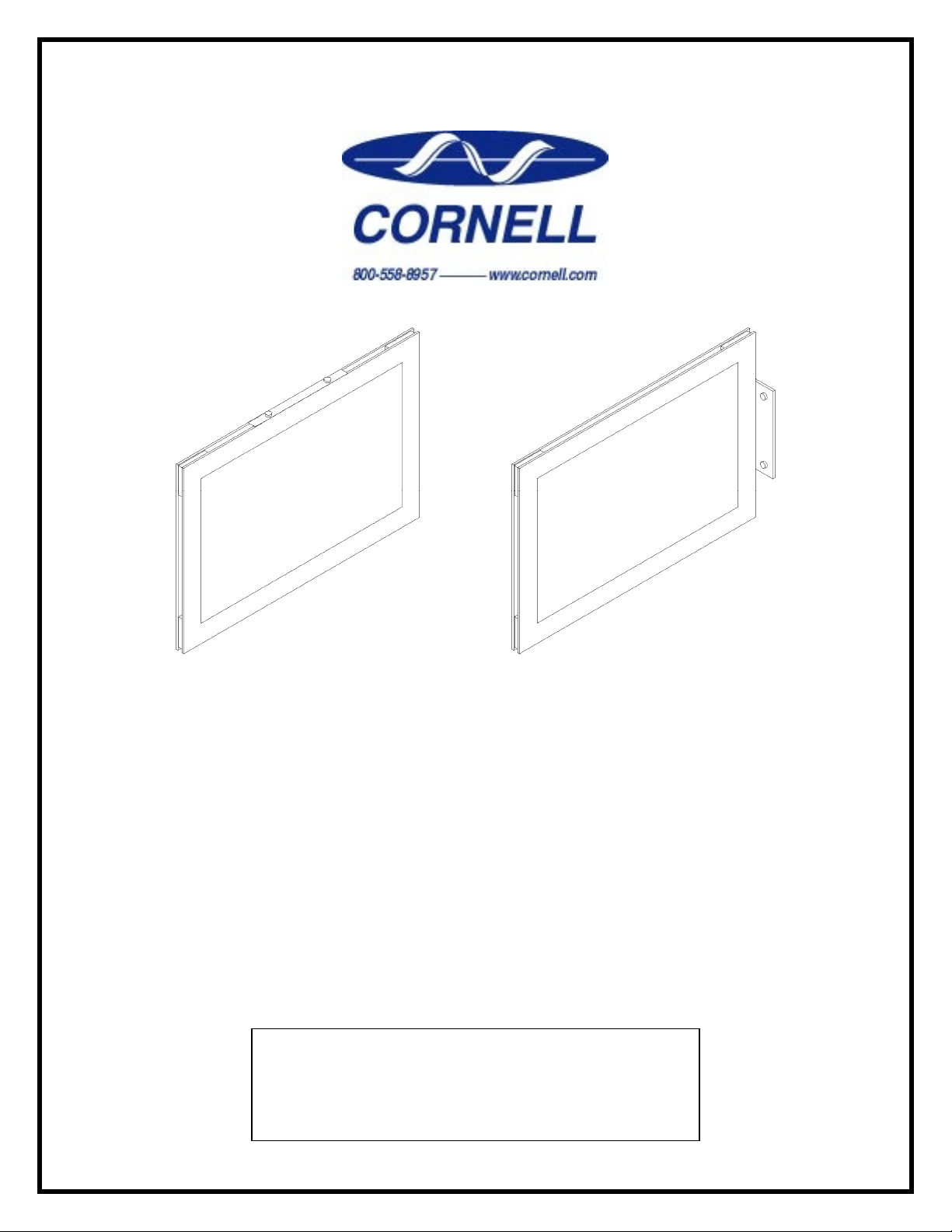
SN-LM42 “Brilliance” Series
Photoluminescent Area of Rescue Signs
This series consists of the following:
Model SN-LM42D
Model SN-LM42DR
Model SN-LM42S
Model SN-LM42SR
CAUTION:
In order for these signs to operate as intended,
the installed location MUST meet certain
minimum ambient lighting levels.
Page 2

The SN-LM42 “Brilliance” Series Photoluminescent Signs provide a simple means to
provide illuminated signage for Area of Rescue Assistance / Area of Refuge applications.
Because they “Glow-in-the-Dark” upon power failure – using high-performance materials,
they do not require any field wiring.
This guide is intended to assist you in the installation of such signs.
A. MODEL NUMBERS / STANDARD FACTORY CONFIGURATIONS:
SN-LM42 Brilliance Series Photoluminescent Signs are available in the following Standard Model Numbers /
Configurations:
CORNELL SINGLE / DOUBLE
MODEL NUMBER: SIDED : LABELING ON SIGN:
SN-LM42S Single-Sided “AREA OF RESCUE ASSISTANCE”
SN-LM42SR Single-Sided “AREA OF REFUGE”
SN-LM42D Double-Sided “AREA OF RESCUE ASSISTANCE”
SN-LM42DR Double-Sided “AREA OF REFUGE”
The following Mounting Hardware is included with the signs:
Wall-Mount Flag / Ceiling-Mount
Hardware: Hardware:
• Single-Sided X X
• Double-Sided X
B. REPLACEMENT PARTS:
In case certain parts are damaged or lost, the following parts can be ordered separately:
CORNELL QTY NEEDED
PART NUMBER: DESCRIPTION : PER SIGN:
5780-116 Flag / Ceiling-Mount Bracket 1
5780-117 Wall-Mount Bracket 2
5930-009 Stick-On Directional Arrow (as needed)
C. INSTALLATION TOOLS & MATERIALS:
The following tools may be needed for installation of Cornell SN-LM42 Series Photoluminescent Signs:
• Number 2 Philips Screwdriver
(Offset version may be needed, if using wall-mount near to the ceiling)
• Drill suitable for bits being used
• Drill Bits:
¼-inch Masonry Bit – for use with included anchors for concrete / mortar surfaces
¼-inch High-Speed Bit – for use with included anchors for drywall surfaces
3/32-inch Bit – where anchor screws will fasten directly into wood structure
Other Sizes (as recommended by mfgr of anchoring system) – where other wall /
concrete / masonry anchors are required
• Other anchors – for fastening to other materials / wall-types, as required
Rev 8/7/2009 page 2 of 7
Page 3
STEP 1 - CHOOSE A LOCATION FOR EACH SIGN:
Locations and mounting heights for such signs are dependent upon local Building Code requirements.
If your project involves an Architect and/or Engineer – they should be able to provide guidance.
If your project is design / build, or if your firm is the only contractor – you need to familiarize yourself with
local Code requirements, and should probably consult with your local Authority Having Jurisdiction
(building inspector / Fire Department official with jurisdiction regarding Building Egress issues).
In order to ensure proper operation, Cornell SN-LM42 Series signs require the following minimum ambient
illumination:
• DEFINITION – In this case, “ambient” shall be defined to mean at all times when the building is occupied.
• MINIMUM AMBIENT ILLUMINATION = 54 lux on the face(s) of the sign
• LIGHT SOURCES = In order for the signs to function properly, the Ambient Illumination needs to be
within a certain range of the visible light spectrum. The best way to ensure this, is to be certain that the
Ambient Illumination Sources consist of one or more of the following:
Flourescent Light Fixtures / Bulbs
Metal Halide Light Fixtures / Bulbs
Mercury Vapor Light Fixtures / Bulbs
If you suspect that the light level at a proposed location is marginal, one way to know for sure is to check
with a light meter. (Be sure to use one that reads in lux units, is suitable for the lighting types being read,
and place and place the meter “eye” on the face of the sign, while holding it in the proposed location.)
If the illumination at a proposed location is provided via a variety of sources, be sure to temporarily turnoff, block, or cover any light sources that are not listed above when metering light levels (Incandescent
lamps / fixtures, windows, etc.).
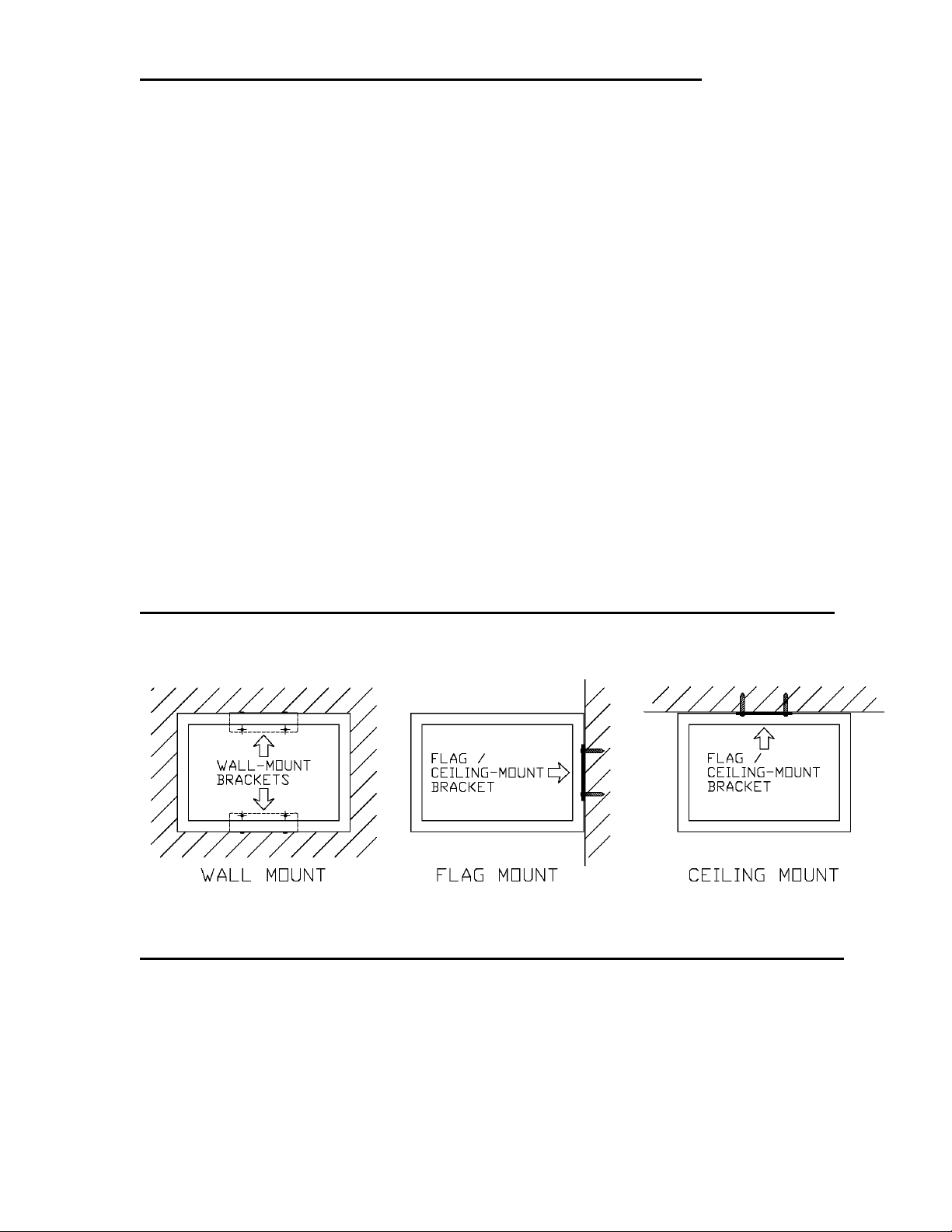
STEP 2 - CHOOSE THE MOUNTING METHOD FOR EACH SIGN:
Cornell SN-LM42 Series signs may be mounted to the building structure via any of the following methods:
(Refer to the pictures below)
STEP 3 - APPLY DIRECTIONAL ARROWHEADS TO EACH SIGN:
Cornell SN-LM42 Series signs include a set of RED Arrowhead “Stickers”, which may be applied as needed
to each sign, such that where required – the sign will “point the way” to Areas of Refuge, as designated within
the building.
The procedure for application of these arrows is illustrated in the series of photographs included within Figure
3 (see next page).
Note: Cornell recommends applying the arrowheads to each sign prior to mounting it, because doing so
usually produces neater results
Rev 8/7/2009 page 3 of 7
Page 4

3A. Grab an Arrowhead sticker from the bag 3B. Peel-off the backing (Keep translucent
that is included with each sign kit. cover sheeting attached as shown – it
provides a “handle” for alignment)
3C. Barely touch the adhesive side of the 3D. Once properly aligned, smooth the arrowhead
Arrowhead to the sign, and align the “stem” down. Gently squeeze-out any air bubbles.
of the Arrowhead with the line (no overlap)
3E. Remove the translucent Cover Sheeting. 3F. Repeat Steps 3A through 3E if needed, for
The other Arrowhead. Otherwise, proceed
With mounting of the sign.
Figure 3. Application of Directional Arrows to Signs
Rev 8/7/2009 page 4 of 7
Page 5

STEP 4 - SELECT THE APPROPRIATE TEMPLATE FOR EACH SIGN:
SIGN
3-1/2 inches
EDGE OR TOP OF SIGN
SIGN
Bracket
Bracket
3-1/2 inches (V)
11-1/2 inches (H)
SIGN
Bracket
Bracket
3-1/2 inches (H)
7 inches (V)
Included with each Cornell SN-LM42 Series sign is a set of two Mounting Templates, as follows:
(If they are lost, they may be obtained from the Cornell Website: www.cornell.com)
• Cornell Part Number D-SN420-MTC = Ceiling / Flag-Mount Template (on 8-1/2” X 11” paper)
• Cornell Part Number D-SN420-MTW = Wall-Mount Template (on 11” X 17” paper)
Each Mounting Template has been printed to scale, such that it will accurately show the locations of the
required mounting holes, along with reference lines for centering or aligning the sign on the mounting surface.
The template may be temporarily held in place, or may be taped in place with masking tape.
STEP 5 - MARK AND/OR DRILL THE MOUNTING HOLES:
WHERE SHOWN ON THE SELECTED MOUNTING TEMPLATE, MARK AND/OR DRILL (4) MOUNTING
HOLES – SIZED AS REQUIRED FOR THE HARDWARE THAT WILL BE USED TO FASTEN THE
APPROPRIATE BRACKETS TO THE MOUNTING SURFACE.
• If you will be using the drywall / masonry anchors included with the sign, drill ¼-inch holes
• If you will be using the included wood/sheet-metal screws, drill 3/32-inch holes
If you have lost or do not have access to the Mounting Templates, you may use the following measurements,
on centers, for marking and drilling the mounting holes (Mounting Holes will lay-out in a rectangular pattern):
WALL- MOUNT:
• Wall-Mount Brackets at Top
& Bottom edges of the sign
(See “Step 2” – Left Picture,
dashed lines):
• Wall-Mount Brackets at Left & Right edges of the sign (brackets rotated 90-degrees from above):
FLAG / CEILING-MOUNT:
• Flag-Mount – Long Axis should be oriented Vertically (Up / Down). Edge of Sign that meets the wall will
be centered between the screw holes
• Ceiling-Mount – Long Axis should be placed Perpendicular (At a right angle) to the direction from which
the sign will normally / most likely be viewed.
Bracket
(Ceiling)
Rev 8/7/2009 page 5 of 7
Bracket
(Flagl)
LONG AXIS
1-1/2 inches
GOES THIS WAY
Page 6

WALL-MOUNT = PROCEED WITH “STEP W6”
FLAG / CEILING MOUNT = SKIP AHEAD TO “STEP F6”
STEP W6 - WALL MOUNT - MOUNT BRACKETS TO THE WALL:
Fasten the Wall Mount Brackets to the wall surface using (4) suitable screws and/or wall anchors. The bent
flanges on the brackets should be oriented outwards from the mounting screws, such that the mounting
screws will be hidden behind the sign, once it is installed. (You may want to avoid completely “snuggingdown” these fasteners until the next step)
• If brackets will be placed vertically, (as shown in the left picture within Figure 2), the flanges go to the
extreme top and bottom
• If the brackets will be placed horizontally, the flanges to the extreme right and left
STEP W7 - WALL MOUNT - MOUNT SIGN TO BRACKETS:
Test-Fit the sign between the Wall Mount Bracket Flanges. When placed correctly, the flanges on the
brackets should be in contact with the edges of the sign. If this is not the case, loosen the screws inserted
during Step W6, adjust the brackets, and test-fit again. When proper placement is achieved, tighten the
screws / anchors that hold the brackets to the wall surface.
Place the sign between the Wall Mount Brackets, and insert (4) #8-32 X ¼-inch Pan-Head Machine Screws
through the holes in the bracket flanges, and into the captive threaded nuts located within the slot that runs
around the edges of the sign.
If needed, the sign may be shifted to the Right and Left (with brackets arranged vertically) or Up and Down
(with brackets arranged horizontally), in order to align the sign as desired. Once all four Machine Screws are
tightened, the sign should be firmly held in place.
* END OF WALL-MOUNT INFORMATION *
For tamper-resistant installations, replace the Machine Screws with (4) #8-32 X ¼-inch Tamper-Resistant
screws of your choice, and use a thread-locking agent on the screw threads (such as lock-tite).
STEP F6 - FLAG / CEILING MOUNT - MOUNT BRACKET TO SIGN:
Locate the Flag / Ceiling-Mount Bracket (Flat piece of Aluminum – approximately 1/8-inch thick), within the
Bracket Kit that is included with each sign.
• If the Sign will be Ceiling-Mounted – Attach the Flag / Ceiling-Mount Bracket to the Top of the sign
• If the Sign will be Flag-Mounted – Attach the Flag / Ceiling-Mount Bracket to the Top of the sign
The Bracket secures to the sign via (2) #8-32 X ¼-inch Flat-Head Machine Screws. Insert the screws into the
two counter-bored (conical) holes centered in the short ends of the bracket. The screws engage the captive
threaded nuts located within the slot that runs around the edges of the sign. The sliding nuts permit the sign
to be adusted Up & Down if Flag-Mounted / Side-to-Side if Ceiling-Mounted, and will hold their position once
the screws are tightened.
STEP F7 - FLAG / CEILING MOUNT - MOUNT SIGN TO WALL / CLG:
Fasten the Sign to the Wall or Ceiling, via (4) suitable screws and/or wall anchors – the screws / anchors pass
through the four exposed holes in the bracket, and insert into the holes that were drilled per Steps 4 and 5.
D. CLEANING:
When the signs need to be cleaned, use a soft, damp cloth (no chemical cleaners)
Rev 8/7/2009 page 6 of 7
Page 7

E. MAINTENANCE / TESTING:
SIGN INVENTORY:
Cornell recommends that the facility owner should develop an inventory of all installed Area of Rescue
Signage. Information recorded should include, but does not need to be limited to the following:
• Building (if the signs are installed within a multi-building complex)
• Floor (if the building is multi-story)
• Installed location (example: “West Wing Corridor, outside NW Stairwell”)
• Mounting configuration
• Arrows installed on each face (which way do they point?)
• When the signs need to be cleaned, use a soft, damp cloth (no chemical cleaners)
INSPECTION:
Using the Sign Inventory document(s), signs should be inspected on a regular basis. Cornell recommends a
minimum interval of at least once annually. This visual inspection should check for secure mounting, and
should verify that the sign has not been damaged or vandalized.
TESTING:
Using the Sign Inventory document(s), signs should be tested for proper operation on a regular basis. Cornell
recommends a minimum interval of at least once annually.
This test should be conducted at a time when interruption of normal illumination will not adversely affect
occupants of the building (or will minimally affect them when this is not possible). Such testing should be
conducted during nighttime hours for building areas that receive natural light
During such tests, all light sources in the area should be switched off, and each sign should be visually
checked, in order to ensure that it glows properly.
F. FREQUENTLY-ASKED QUESTIONS:
F1. HOW LONG WILL THE SIGN GLOW?
Once the sign has had a chance to properly charge-up via proper lighting sources (see “Step 1”) the
sign will remain highly visible in the dark for approximately 20 minutes, with some residual glow
remaining for up to 60 minutes.
F2. HOW LONG WILL THE SIGNS LAST?
Under normal use, the material used in the signs has a life expectancy in excess of 25 years.
F3. HOW CLOSE TO A LIGHT FIXTURE SHOULD EACH SIGN BE INSTALLED?
There is no set distance. Operation of the sign is dependent upon minimum illumination levels falling
onto the sign face, as well as the source(s) of such illumination (see “Step 1” for more information).
Areas where either face of the sign will be in strong shadows should be avoided
Areas with light-colored and/or shiny walls and floors will provide more indirect illumination
Areas with dark-colored and/or flat-finish walls and floors absorb light. In such cases, each sign
should be placed near light fixtures that will direct light to the installed sign location.
Light fixtures that provide indirect light increase the odds that light will fall where it is needed.
Light fixtures that provide highly-directed light (spot lights and fluorescent with parabolic
reflectors) will decrease the odds that light will fall where it is needed.
F4. DO THE SN-LM42 BRILLIANCE SERIES SIGNS MEET CURRENT CODE REQUIREMENTS?
Currently, there is no set Code / Standard for Illuminated Area of Rescue Assistance signage.
However, although the SN-LM42 Series Signs themselves have not been tested for compliance, the
materials used within these signs are designed to meet or exceed current standard for means of
egress (Exit) signage. Such standards include the following:
UL 924 Standard for Emergency Lighting & Power Equipment (Underwriters Laboratories)
IBC International Building Code – 2003 Edition (Section 1011)
OSHA 1910.37 Means of Egress
Rev 8/7/2009 page 7 of 7
 Loading...