

Page 1
TECHNOLOGY
USER MANUAL
Jazz GB2 Video Door
Entry System Kit
2-wire installation
Code 50122156 T ENJAZZ VESTA2-VESTA7 REV.0 14 7
Page 2
JAZZ GB2 VIDEO DOOR ENTRY SYSTEM KIT - HOUSE
INTRODUCTION
First of all, we thank and congratulate you for purchasing this product.
Our commitment to achieving the satisfaction of customers like you is manifested through our ISO-9001 certification
and the manufacture of products like the one you have just purchased.
Its advanced technology and strict quality control will ensure that customers and users enjoy the numerous features
that this device offers. To get the most out of them and ensure proper operation from day one, we recommend that you
read this instruction manual.
CONTENTS
Introduction....................................................................................................................................................................2
Contents........................................................................................................................................................................2
Set-up warnings............................................................................................... ................................. 2............................ .
Safety precautions.......................................................................................... ...................................................3............
Characteristics.............................................................................................................................................................. 3.
System operation.................................................................................................... ....................................... 3............... .
Description of JAZZ surface panel....................................................................................... .......................................4....
Exploded view of the parts of the JAZZ panel.......................................................................................... .......................5. .
Door panel.......................................................................................................................................................................
............................................................................................................................................5Location of the door panel
............................................................................................................................................6Removing the metal front
.......................................................................................................................................... 6.Positioning the door panel
.................................................................................................................................................. 6Wiring the door panel
............................................................ ........................... 7...................... .Codes assigned to the door panel call buttons
.............................................................................. .......................... 7...............................Description of the DIP switch
........................................................................ ............................................ ..8. .Description of the configuration jumper
....................... ......................................................8...............Description of the illumination LEDs (low light conditions)
...................................................... ...............................................8..Description of the visual signals on the door panel
............................................................................................................8.Setting the doorpanel communication volume
.................................................................................. ...................9............................Setting ringtone operating mode
...................................................... ......................................9...Setting door panel mode with or without shield installed
.............................. .................. 9..........Setting contact mode for CV-/CV+(lock release) and C1/NA1 (auxiliary device)
.................................. ........10....... .Setting the activation time for CV-/CV+(lock release) and C1/NA1 (auxiliary device)
........................................................................ ............10....................Setting card reader illumination operating mode
................................................................. ............10.....................Setting door panel illumination LED operating mode
.................................................................................................................... .............11.Setting the door panel address
............................................................................................................... ................ 11. .Positioning the nameplatelabel
.................................................... ......................................... 11.................... .Positioning the button identification labels
............................................................................................. ...............................................12...Closing the door panel
Installing the power supply unit (FA-GB2/A)and lock release....................................................................................... 13.
Wiring diagrams with the VENTA2 monitor.................................................................................. .................. 14-19......... .
Wiring diagrams with the VESTA7 monitor................................................................................... ................. 20-25......... .
Connection diagrams for up to 4 access panels............................................................................ ....................... ...26..... .
Connection diagrams withAC lock release, 2nd AC lockrelease or automatic gate..................... ........ 27......................... .
2
SET-UP WARNINGS
- Do not overtighten the screws on the power supply connector.
- Always disconnect the power supply before installing or making modifications to the devices.
- The fitting and handling of these devices must be carried out by .authorised personnel
- The wiring must run at least .40cm away from any other wiring
- Before connecting the device to the mains, check the connections between the door panel, power supply unit,
distributors,
- Use the Golmar cable (2x1mm ).RAP-2150
- Always follow the instructions contained in this manual.
camera
interface, GSM interface (VESTA2 monitor only) and monitors.
2
Page 3

JAZZ GB2 VIDEO DOOR ENTRY SYSTEM KIT - HOUSE
SAFETY PRECAUTIONS
- Always disconnect the power supply before installing or making modifications to the devices.
- The fitting and handling of these devices must be carried out by .authorised personnel
- The wiring must run at least 40 cm away from any other wiring.
- On the power supply unit:
wDo not overtighten the screws on the connector.
wInstall the power supply unit in a dry protected location free from the risk of dripping or splashing water.
wAvoid locations that are humid, dusty or near heat sources.
wEnsure that the air vents are free from obstruction so that air can circulate freely.
wTo avoid damage, the power supply unit must be firmly secured in place.
wTo prevent electric shock, do not remove the cover or handle the wires connected to the terminals.
CHARACTERISTICS
- Video door entry system with simplified wiring (non-polarised 2-wire bus).
- Up to 4 access panels (DP-GB2Adistributor required for more than one access panel) per installation.
- Up to 2 apartments per installation.
- Maximum 6 Vesta2monitors or 4 Vesta7 monitors perinstallation.
- Maximum 4 monitors in parallel (without distributors) per installation.
- In installations with 1 apartment, maximum 6 Vesta2monitors or 4 Vesta7 monitors.
-In installations with 2 apartments, maximum 6 Vesta2monitors or 4 Vesta7 monitors.
- Combinations with Vesta2monitors:
w1 monitor in one apartment and 5 monitors in the other apartment.
w3 monitors in each apartment.
- Combinations with Vesta7monitors:
w1 monitor in one apartment and 3 monitors in the other apartment.
w2 monitors in each apartment.
-Visual signals on the door panel for people with impaired hearing (indicating call process, communication, door open
and channel busy).
- Door opening and auxiliary device activated for 5 seconds (configurable).
- DC lock release.
- Potential-free contact for activation of auxiliary devices (2nd AC lock release, gate, etc.); do not exceed values of
12Vdc/1Abetween terminals 'C1' and 'NA1' on the door panel.
- Input for exterior door opening button (output 'CV-'and 'CV+').
- Confirmation tone when the call button is pressed.
- DIP switches to configure door panel address, call mode, door panel with/without shield, type of contact/time for lock
releaseand auxiliary device output,card reader illumination mode and LED function mode (low light conditions).
- Maximum distance between the power supply and the furthest door panel: 65m with a cross-section of 1mm .
- Maximum distance between the power supply and the last distributor: 60m with a cross-section of 1mm .
- Maximum distance between distributor and monitor: 30m with a cross-section of 1mm .
2
2
2
3
SYSTEM OPERATION
- To make a call, the visitor must press the button of the apartment; an audible sound indicates that the call is being
made and LED will turn on. At thismoment, the apartment's monitorsreceive the call. Ifanother apartment is called
by mistake, press the button for the correct apartment and the first call will be cancelled.
- In systems with several access doors, the other door panel(s) will be automatically disconnected. If another visitor
tries to call, a number of telephone tones will be heard to indicate that the system is busy and LED will illuminate.
- The call lasts for 40 seconds. The image appears on the monitor (with code 0 'apartment 1' or code 16 if the call is in
'apartment 2') when receiving the call without the visitor knowing.
If the call is not answered within 40 seconds, LED will turn off and thechannel will be freed.
- To establish communication, press button on any monitor in theapartment. Door panel LED will turn on.
If the monitor is a VESTA2 GB2/H or VESTA7 GB2/H with icon on the front, make sure that the hearing aid is
between 15 and 25 cm away from the monitor to ensure maximum audio quality during communication with the
door panel.
- Communication will last for one and a half minutes or until button is pressed again. When communication has
finished, LEDs and willturn off and the channel will be freed.
-To open the door, press button during the call or communication processes: one press will activate the lock release
for five seconds and LED will also turn on for five seconds.
-To activate theauxiliary deviceoutput, press button on the Vesta7 monitor or via the Vesta2 monitor's lock release
menu 2 (for lock release 2, it is necessary to enable lock release function 2 on the Vesta2 monitor) during call or
communication processes: a single press activates the auxiliary device output for five seconds, LED will also
illuminate for five seconds.
- For a description of the functioning and setup of the monitor,see the monitor's user manual.
Page 4
JAZZ GB2 VIDEO DOOR ENTRY SYSTEM KIT - HOUSE
DESCRIPTION OF THE JAZZ SURFACE PANEL
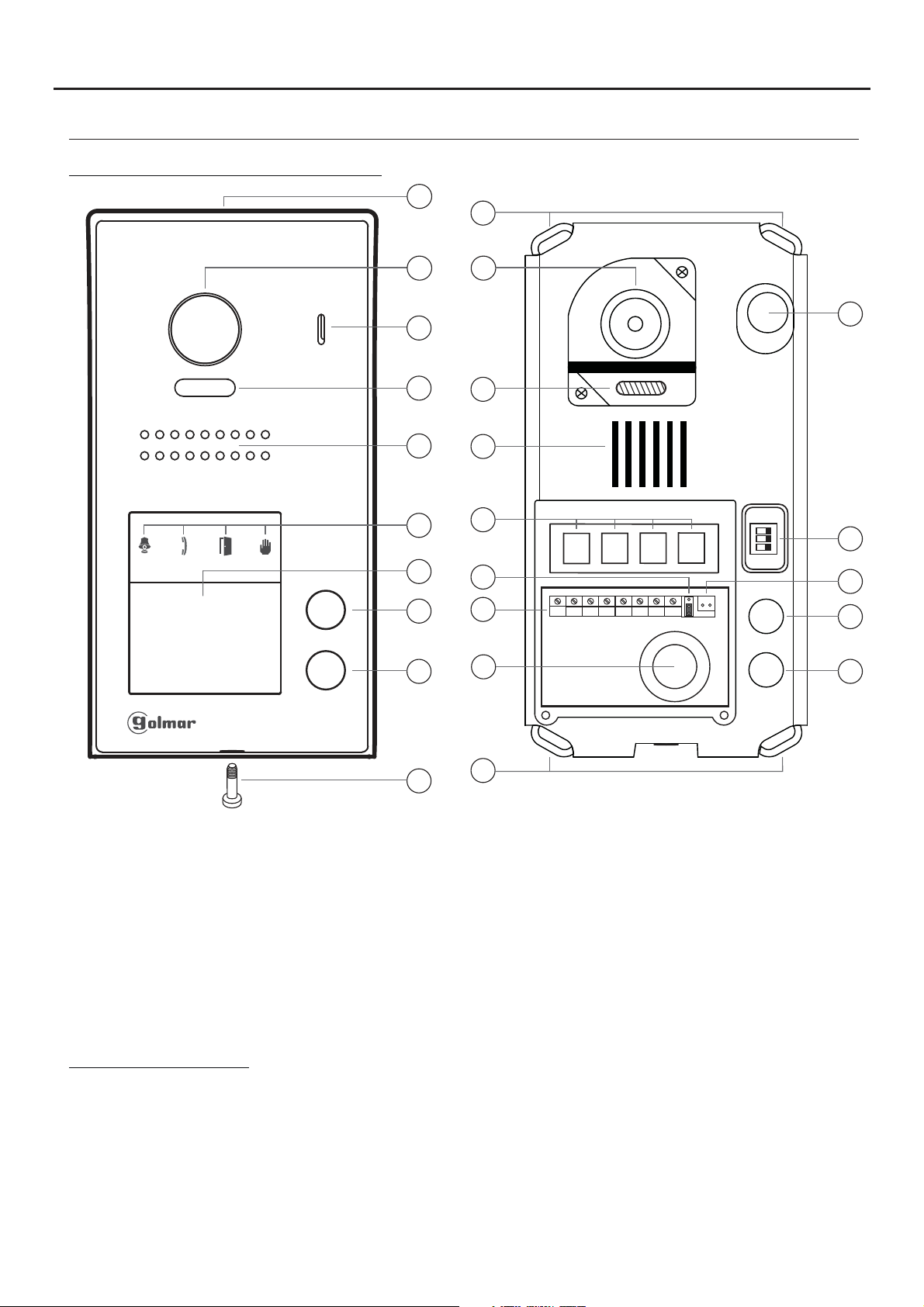
Description of the JAZZ surface panel:
a
k
4
b
c
d
e
g
h
b
c
d
e
f
i
f
m
n
1 2 3
ON
l
AP-
AP+
NA1
C1
CV+
CV- BUSBUS
o
p
h
i
a.
Shield.
b. Colour television camera.
c. Microphone.
d. LEDs (activation with ambient light).
e. Speaker.
f. LEDs (visual signals for people with
impaired hearing).
g. Nameplate label.
h. Call button apartment 2.
(2-button door panel models only).
Connection terminals:
_
AP +,AP :
C1
NA1
_
CV ,CV+
BUS
BUS
Input for exterior door opening button (CV-, CV+).
: Contact 'C' for auxiliary device (2nd AC lock release, gate, etc.).
: Contact 'N.O.' for auxiliary device (2nd AC lock release, gate, etc.).
: 12Vdc output for Golmar DC electric lock.
: Communication BUS (non-polarised).
: Communication BUS (non-polarised).
j
k
i. Call button apartment 1.
j. Metal front fixing screw (x1).
k. Holes for fixing to wall (x4).
l. Do not use (internal use).
m.Connection terminals.
n. Wiring entry.
o. DIP switch.
p. No function.
Note: See wiring diagrams for connections (pp. 14-27).
Page 5
JAZZ GB2 VIDEO DOOR ENTRY SYSTEM KIT - HOUSE
DESCRIPTION OF THE JAZZ SURFACE PANEL
Description of the door panel:
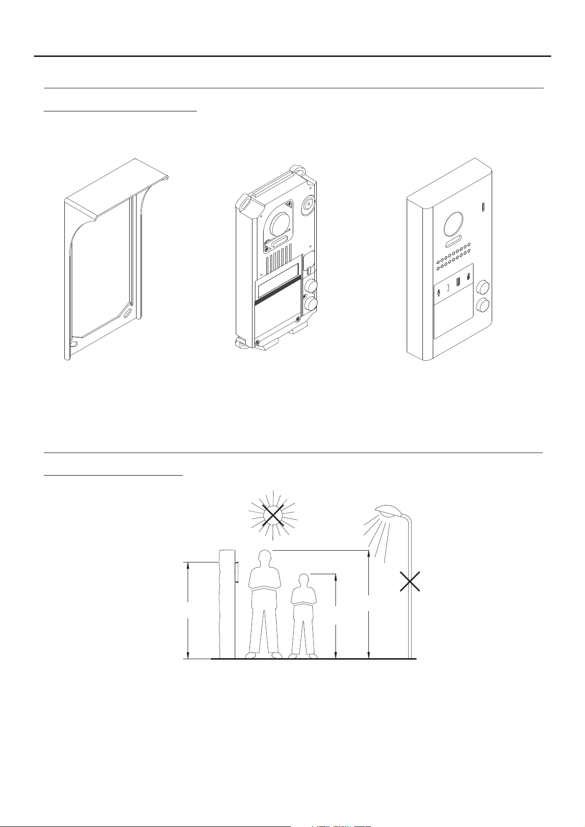
Exploded view of the parts of the panel.
5
Aluminium frontElectronic moduleShield
- JAZZ J5110/VESTA2 1P KIT (Code 11500241).
- JAZZ J5110/VESTA7 1P KIT (Code 11500242).
- JAZZ/1 SURFACE DOOR PANEL (Code 11525401).
- JAZZ/2 SURFACE DOOR PANEL (Code 11525402).
INSTALLATION OF THE DOOR PANEL
Location of the door panel:
1650
1850
1450
Locate the top of the door panel at a height of 1.65m.
The door panel has been designed to withstand diverse environmental conditions. It is however advisable to take
extra precautions to prolong its service life, such as using the shield supplied or locating it in a covered area.
For optimum image quality, avoid direct contact from light sources (sunshine, street lights, etc.).
Page 6
AP-
C1
NA1
AP+
CV- BUSBUS
CV+
JAZZ GB2 VIDEO DOOR ENTRY SYSTEM KIT - HOUSE
INSTALLATION OF THE DOOR PANEL
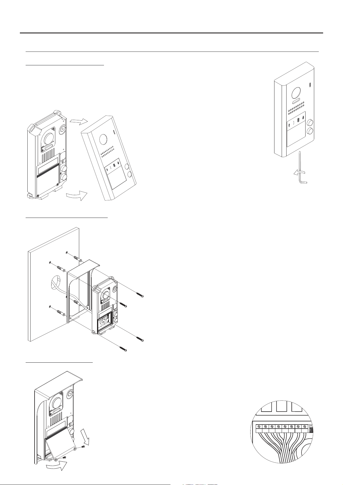
Removing the metal front:
Remove the screw at the bottom of the door panel
using the Allen key supplied with the product.
Remove the metal front as shown in the drawing.
6
Positioning the door panel:
Wiring the door panel:
Present the shield and the electronic module to the wall, placing
the top of the module at a height of 1.65m from the ground, and
pass the wiring through the cable entry.
Make 4 x 6mm diameter holes, two located at the top of the
module and the other two at the bottom, and fix the shield and
electronic module to the wall using the plugs and screws supplied.
Important: The distance between the top of the electronic module
and the shield should be 7mm, so that the metal front can be
correctly positioned when closing the door panel.
To access the connection
terminals, r e m o v e the
nameplate label.
Then connect the wiring to the
connector strip of the electronic
module, following the instructions
in the wiring diagrams.
Page 7
ON
1 2 3
JAZZ GB2 VIDEO DOOR ENTRY SYSTEM KIT - HOUSE
INSTALLATION OF THE DOOR PANEL
Codes assigned to the door panel call buttons:
1 2 3
ON
AP-
AP+
The sound module's P1 and P2 buttons are assigned with factory codes.
NA1
C1
CV+
CV- BUSBUS
Button 'P2': Codes 16-21.
(Apartment 2) 2-button door panels only.
Button 'P1': Codes 0-5.
(Apartment 1).
7
- Apartment 1, button 'P1': Enables codes 0-5 to be assigned to the monitor.
Monitors in this apartment must be set with codes in order of allocation from 0 to 5.
When button 'P1' on the door panel is pressed, all of the monitors in apartment 1 will receive the call and only
the monitor assigned with code 0 will show the door panel image. If the call is answered from any other
monitor in the apartment, the image on the monitor assigned with code 0 will disappear and audio and video
communication will be established with the door panel.
- Apartment 2, button 'P2': Enables codes 16-21 to be assigned (2-button door panel only).
Monitorsin this apartment must be set with codes in order of allocationfrom 16 to 21.
When button 'P2' on the door panel is pressed, all of the monitors in apartment 2 will receive the call and only
the monitor assigned with code 16 will show the door panel image. If the call is answered from any other
monitor in the apartment, the image on the monitor assigned with code 0 will disappear and audio and video
communication will be established with the door panel.
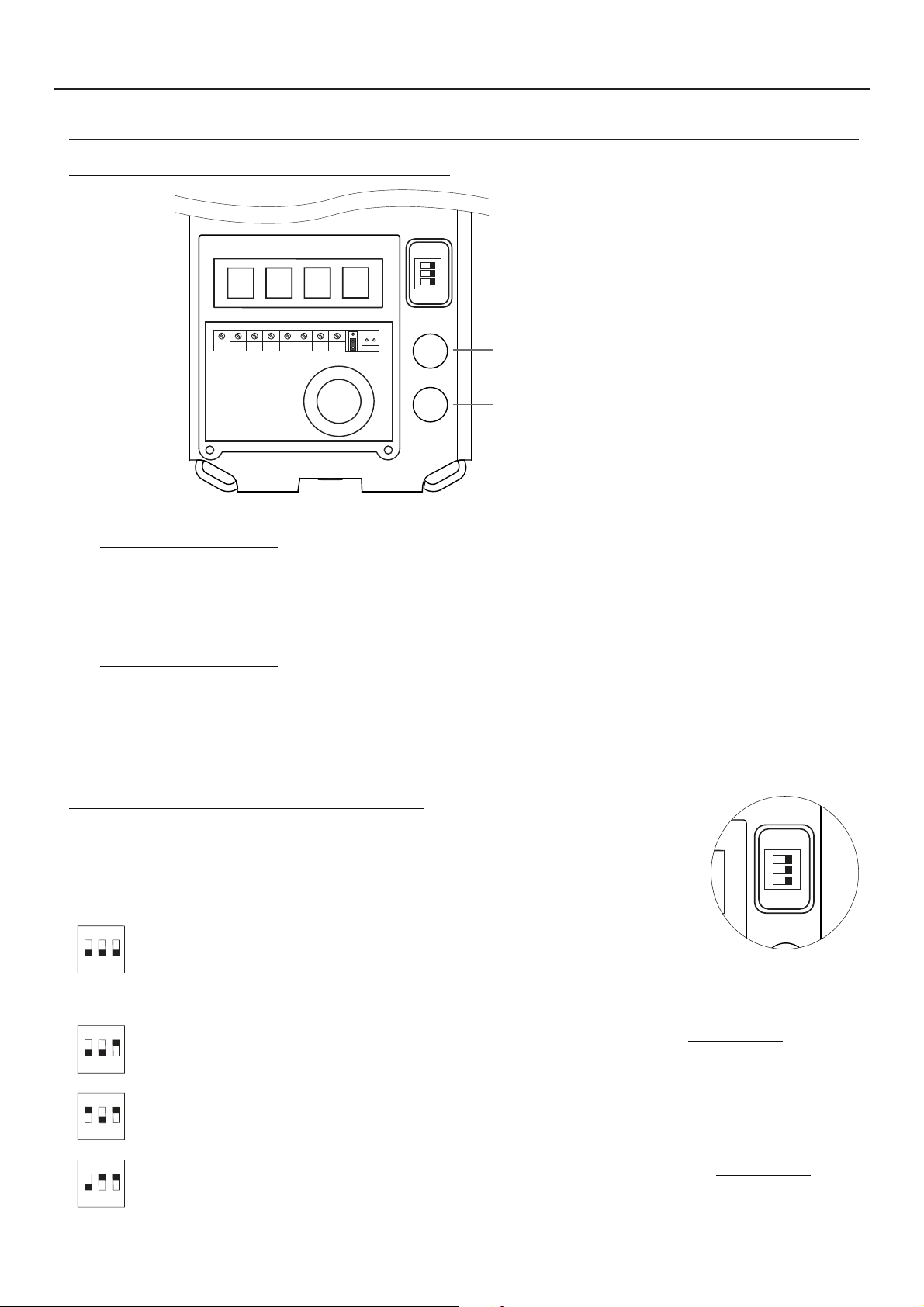
Description of the configuration DIP switch:
The DIP switch is located on the right side of the circuit, accessible by opening the
door panel.
1. To select the address of the door panel (DIP 3 must always be OFF):
( )
*
ON
1 2
Door panel address: (DIP 3 always OFF).
DIP switches: 1 and 2 OFF (address 1), 1 ON and 2 OFF (address 2), 1 OFF and 2
3
ON (address 3), 1 and 2 ON (address 4).
( )
*
2. To configure the door panel (DIP 3 must always be ON):
ON
1 2
ON
1 2
ON
1 2
( )
Factory setting.
*
With DIP 1 and DIP 2 OFF (DIP 3 always ON), the following can be configured: See pp. 9-10.
-With button 'P1', ringtone operating mode during a call process.
3
-With button 'P2', whether the door panel is installed with or without shield.
With DIP 1 ON and DIP 2 OFF (DIP 3 always ON), the following can be configured: See pp. 9-10.
-With button 'P1', lock release output 'CV-' and 'CV+', whether N.O. (factory setting) or N.C.
3
-With button 'P2', activation time of lock release and auxiliary device outputs.
With DIP 1 OFF and DIP 2 ON (DIP 3 always ON), the following can be configured: See pp. 9-10.
-With button 'P1', operating mode of card reader illumination.
3
-With button 'P2', operating mode of door panel illumination LEDs with low light.
Page 8
JAZZ GB2 VIDEO DOOR ENTRY SYSTEM KIT - HOUSE
INSTALLATION OF THE DOOR PANEL
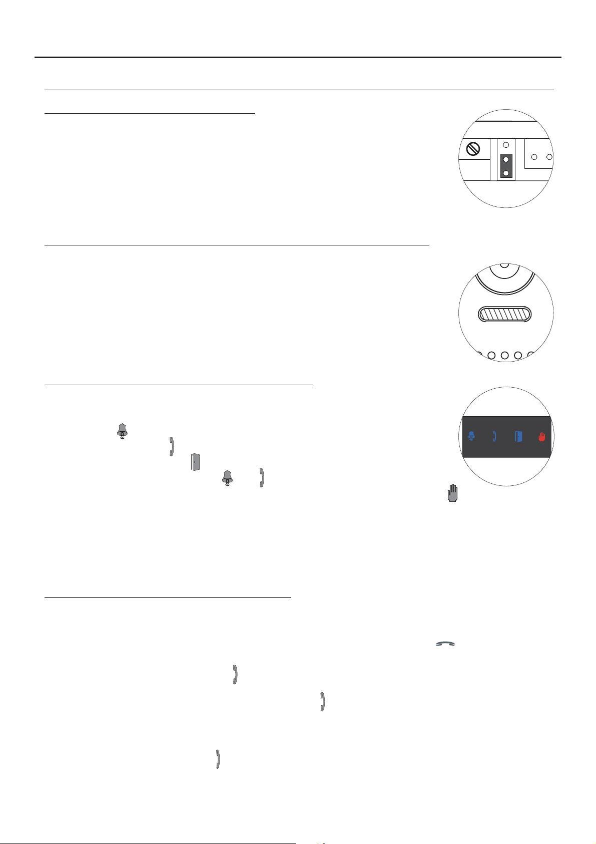
Description of the configuration jumper:
Important: Do not change the configuration jumper's factory position.
( )
Factory setting.
*
Description of the door panel illumination LEDs (for low light conditions):
The door panel lighting LEDs will turn on during a call if the door panel lighting at
that moment is low. This enables the user to view the person who has called
from the apartment monitor.
( )
*
8
Description of the visual signals on the door panel:
Visual signals on the door panel for people with impaired hearing, indicating:
- In call: LED ' ' will illuminate during in call and in communication times.
- In communication: LED ' ' will illuminate during the communication process.
*
- When the door is open: LED ' ' will illuminate when the door is open.
- When ending communication: LEDs ' ' and ' ' will turn off.
- With more than one door panel, when calling and one is already in communication: LED ' ' will illuminate for
10 seconds.
- In call and the monitor is in 'Do not disturb' mode: No LED will illuminate, the door panel will emit a quick tone.
- In call (apartment without monitor or telephone): No LED will illuminate, the door panel will emit 3 quick tones.
Note: Communication in auto switch-on mode does not occupy the channel and the door panel communication
*
LED does not illuminate.
Setting the door panel communication volume:
If the audio volume of the door panel is too low after turning it on, follow these steps:
- Call the apartment.
- When the call is received in the apartment, establish communication by pressing button on the monitor.
- Then press the button used to call the apartment for 3 seconds until a number of confirmation tones are heard
and door panel communication LED starts to blink.
- Each press on the call button will increase the door panel volume and blink speed of the LED.
.
There are 5 volume settings and the blink speed of LED will increase for each. Slow to fast blink - low to
high volume. After reachingsetting 5, maximum blinkspeed and volume, the nextsetting is 1, minimumblink
speed and volume (carousel mode).
- To save the volume setting, keep the button pressed until a number of confirmation tones are heard and the
door panel communication LED turns on.
Page 9

P1
P2
P1
JAZZ GB2 VIDEO DOOR ENTRY SYSTEM KIT - HOUSE
INSTALLATION OF THE DOOR PANEL
Setting ringtone operating mode:
To configure the door panel ringtone when making a call, follow these steps: See p. 7.
- In the configuration DIP switch, set DIP 1 andDIP 2 to OFF and DIP 3 to ON.
- The card reader illumination will blink slowly.
- Thenwith the P1 callbutton, each pressselects adifferent option and in carousel mode:
If pressed once: Configure the door panel with one ringtone.
LED illuminates and the door panel emits a long tone.
If pressed : Configure the door panel to hear tones during the call process.a 2nd time
LED illuminates and the door panel emits two tones.short
If pressed : Configure the door panel without a ringtone (factory setting).a 3rd time
LEDs and illuminate and the door panelemits three tones.short
- Once the required option is selected, stop pressing P1. Then set DIP 3 to OFF and the door panel
will exit configuration, saving the selected option. Remember to configure the address of the door panel.Note:
9
Setting door panel mode with or without shield installed:
To configure the door panel with or without shield installed, follow these steps: See p. 7.
- In the configuration DIP switch, set DIP 1 andDIP 2 to OFF and DIP 3 to ON.
- The card reader illumination will blink slowly.
- Thenwith the P2 callbutton, each pressselects adifferent option and in carousel mode:
If pressed once: Configure the door panel with shield installed (factory setting).
LED illuminates and the door panel emits a long tone.
If pressed : Configure the door panel without shield installed.a 2ndtime
LED illuminates and the door panel emits two tones.short
- Once the required option is selected, stop pressing P2. Then set DIP 3 toOFF and the door
panel will exit configuration, saving the selected option.
Note: Remember to configure the address of the door panel.
Setting contact mode for CV- and CV+ (lock release) and C1 and NA1 (auxiliary device):
To change the contact mode for lock release and auxiliary device activation, follow these steps: See p. 7.
- In the configuration DIP switch, set DIP 1 toON, DIP 2 to OFF and DIP 3 to ON.
- The card reader illumination will blink slowly.
- Thenwith the P1 callbutton, each pressselects adifferent option and in carousel mode:
If pressed once: Configure the door panel with contact mode N.A. (factory setting).
LED illuminates and the door panel emits a long tone.
If pressed : Configure the door panel with contact mode N.C.a 2nd time
LED illuminates and the door panel emits two tones.short
- Once the desired option is selected, set DIP3 to OFFand thedoor panelwill exitconfiguration,
saving the selected option.
Note: Remember to configure the address of the door panel.
Important: The type of contact selected will be for both the lock release and theauxiliary device.
Page 10

P2
P1
P2
JAZZ GB2 VIDEO DOOR ENTRY SYSTEM KIT - HOUSE
INSTALLATION OF THE DOOR PANEL
Setting the activation time for CV- and CV+ (lock release) and C1 and NA1 (auxiliary device):
To change the activation time for the lock releaseand auxiliary device, followthese steps: See p. 7.
- In the configuration DIP switch, set DIP 1 toON, DIP 2 to OFF and DIP 3 to ON.
- The card reader illumination will blink slowly.
- Then press and hold down call button P2; LED will blink indicating with each blink 1 second and also a tone will
indicate every timeit is heard 1 second for the activation time.
- Once the desired activation time is configured, set DIP 3 to OFF and the door panel will exit
configuration, saving the setting.
Note: Remember to configure the address of the door panel.
Important: The time configured will be for both the lock release and theauxiliary device.
Setting card reader illumination operating mode:
10
To configurethe card reader illumination operating mode, follow thesesteps: See p. 7.
- In the configuration DIP switch, set DIP 1 toOFF, DIP2 to ON and DIP 3 to ON.
- The card reader illumination will blink slowly.
- Thenwith the P1 callbutton, each pressselects adifferent option and in carousel mode:
If pressed once: Card reader always illuminated (factory setting).
LED illuminates and the door panel emits a long tone.
If pressed : Card reader always off.a 2nd time
LED illuminates and the door panel emits two tones.short
If pressed time:The card reader automatically turns on or off dependinga 3rd
on the ambient light (day/night mode).
LEDs and illuminateand the door panel emits three tones.short
- Once the required option is selected, stop pressing P1. Then set DIP 3 to OFF and the door panel will exit
configuration, saving the selected option. Remember to configure the address of the door panel.Note:
Setting door panel illumination LED operating mode:
To configure the door panel illumination LED operating mode, follow these steps: See p. 7.
- In the configuration DIP switch, set DIP 1 toOFF, DIP2 to ON and DIP 3 to ON.
- The card reader illumination will blink slowly.
- Thenwith the P2 callbutton, each pressselects adifferent option and in carousel mode:
If pressed once: Illumination LEDs always activate when a call is made from the door panel
LED illuminates and the door panel emits a long tone.
If pressed : Illumination LEDs always off.a 2nd time
LED illuminates and the door panel emits two tones.short
If pressed time: Illumination LEDs activate when a call is made and door panela 3rd
illumination at that moment is low (factory setting).
LEDs and illuminateand the door panel emits three tones.short
.
- Once the required option is selected, stop pressing P2. Then set DIP 3 to OFF and the door panel
will exit configuration, saving the selected option. Remember to configure the address of the door panel.Note:
Page 11

ON
1 2 3
JAZZ GB2 VIDEO DOOR ENTRY SYSTEM KIT - HOUSE
INSTALLATION OF THE DOOR PANEL
Setting the door panel address:
11
Configure door panel addresses as described below:
The DIP switch is located on the right side of the circuit, accessible by opening the
door panel.
ON
( )
*
1 2
Important: To select the address of the door panel (DIP 3 must always be OFF).
Door panel address: (DIP 3 always OFF).
DIP switches: 1 and 2 OFF (address 1), 1 ON and 2 OFF (address 2), 1 OFF and 2
3
ON (address 3), 1 and 2 ON (address 4).
Positioning the :nameplate label
After completing the wiring and configuration work, position the
nameplate label in the electronic module. Fix using the screws
supplied.
Important: Before closing the , make a test callnameplate label
to the apartment(s) to ensure that it works correctly.
( )
*
Important: Position the at the top with the black band visible.nameplate label
Positioning the button identification labels:
Open the label cover (figure A ), insert the label (figure B ) andclose (figure C ).
A B C
Open the label cover
( )
*
( )
Customise and download the 'JAZZ LABELLER KIT REV.0117' label from Golmar's documentation website:
*
https://doc.golmar.es/search/manual/50180198
Page 12

JAZZ GB2 VIDEO DOOR ENTRY SYSTEM KIT - HOUSE
INSTALLATION OF THE DOOR PANEL
Closing the door panel:
To finish the mounting of the doorpanel, replace the
metal front.
Remember: Insert the protective c ofsilicone over
*
the configuration witch.DIP s
Important: only 1 call push buttonDoor panels with ,
**
must cover the hole of the unused button withpush
the circular adhesive supplied withthekit.
Protective cover
*
Door panelwith
**
1 Push button
Adhesive to cover hole of the push button
not used. (Only 1door panels with call
push button).
12
Fix the metal front with the screw using the Allen key
supplied with the product, as shown in the drawing.
Once the work is complete, make a test call to the
apartment(s) to check it works correctly.
Page 13

JAZZ GB2 VIDEO DOOR ENTRY SYSTEM KIT - HOUSE
INSTALLATION OF THE POWER SUPPLY UNIT
Installing the FA-GB2/A power supply unit:
Installthe power supplyunit in a dry protected locationfree from the risk of dripping or splashing water.
To prevent electric shock, do not remove the protective cover of the primary or handle the wiring.
The fitting and handling of this device must be carried out by in the absence of electricalauthorised personnel
current.
To avoid damage, the power supply unit must be firmly secured in place.
Please note that current regulations stipulate that the power
DIN rail.
supply must be protected by a circuit breaker.
Connect the FA-GB2/A power supply unit to the earth
connection.
Mount the DIN rail to the wall with the plugs and screws
supplied.
Then attach the power supply by applying slight
pressure.
13
DIN rail.
DIN rail.
The power supply can be installed on aDIN 46277 rail.
.
To remove the power supply unit from the DIN rail, use a flat
screwdriverto lever it off, as shown in the drawing.
The FA-GB2/Amodel requires 8 elements on therail.
DIN rail latch release.
DIN 46277
IMPORTANT: the maximum number ofunits that canbe connected toan FA-GB2/Apower supply is6 VESTA2
monitors or 4 VESTA7 GB2 monitors.
Replace the protective cover once the input terminals have been wired.
INSTALLATION OF THE LOCK RELEASE
Installing the lock release:
3,5 x 25
DIN-7972
If the lock release is to be fitted to a metal door, use a Ø3.5mm drill bit and
thread the hole made. For wooden doors, use a Ø3mm drill bit.
M 4 x 8
DIN-963
IMPORTANT:
- The lock release must be 12V DC orAC (Golmar).
p. 27 forAC lock release and pp. 14-27 for DC lock release).
(See
- The kit is supplied with two varistors. If connecting an AC lock release to one of the outputs, fit the varistor
supplied
directly to the lock release terminals to ensure the device functions correctly.
Page 14

JAZZ GB2 VIDEO DOOR ENTRY SYSTEM KIT - HOUSE
WIRING DIAGRAMS:
One-apartment installation with VESTA2 monitor and Golmar DC lock release.
14
Distances and
cross-sections:
VESTA2
B
FA- 2GB /A
A
C
Configure the end of line in
*
the last monitor.
DIP 6 to ON.
CODE 0
*
Cable
Twisted pair 2x0.75mm
Twisted pair 2x1mm
( )2
( )2
Distances with Golmar RAP-2150 cable
(twisted pair 2x1mm ).
2
6 m0A50mB10m
2
65m 60m 15m
2
APARTMENT 1
VESTA2
BUS
C
AP
AP-
AP+
Lock release
12 Vcc/270mA.max.
100~240Vac
Access panel
NA1
C1
( )1
( )1
Mains
N L
L
CV- BUSBUSCV+
SW1
ON
1 2 3
CN
FA- 2GB /A
BUS (M) BUS(PL)
Two-apartment installation with 1 VESTA2 monitor per house and Golmar DC lock release.
Distances and
cross-sections:
VESTA2
VEST
A2
B
FA- 2GB /A
A
CODE 16
*
Cable
Twisted pair 2x0.75mm
( )2
Twisted pair 2x1mm
( )2
Distances with Golmar RAP-2150 cable
(twisted pair 2x1mm ).
C
2
6 m0A50mB10m
2
65m 60m 15m
2
BUS
APARTMENT 1APARTMENT 2
VESTA2VESTA2
CODE 0
BUS
Access panel
C
AP-
AP+
C1
100~240Vac
NA1
1
( )
Mains
N L
L
CV- BUSBUSCV+
SW1
ON
1 2 3
FA- 2GB /A
CN
BUS (M) BUS(PL)
Configure the end of line in
*
the last monitor.
6 to ON.
DIP
( )1
Important: For AC lock release, 2nd
AP
Lock release
12 Vcc/270mA.max.
( )1
AC lock release or automatic gate, see wiring diagrams p. 27.
Page 15

JAZZ GB2 VIDEO DOOR ENTRY SYSTEM KIT - HOUSE
WIRING DIAGRAMS:
One-apartment installation with VESTA2 monitors in parallel (In-Out) and Golmar DC lock release.
15
IMPORTANT: Maximum 4 monitors in parallel (without distributors) per installation.
APARTMENT 1
CODE 3
VEST
A2
CODE 2
VESTA2 VESTA2 VESTA2
CODE 1
CODE 0
*
BUS
BUS
BUS
Distances and cross-sections:
VESTA2
B
FA- 2GB /A
A
Cable
Twisted pair 2x0.75mm
( )2
Twisted pair 2x1mm
( )2
Distances with Golmar RAP-2150 cable
(twisted pair 2x1mm ).
Configure the end of line in the last monitor.
*
DIP 6 to ON.
2
6 m0A50mB10m
2
65m 60m 15m
2
C
C
AP
Lock release
Mains
100~240Vac
N L
L
CN
FA- 2GB /A
BUS
Access panel
SW1
ON
1 2 3
AP+
AP-
12 Vcc/270mA.max.
NA1
C1
CV- BUSBUS
CV+
( )1
( )1
BUS (M) BUS(PL)
Two-apartment installation with VESTA2 monitors in parallel (In-Out) and Golmar DC lock release.
IMPORTANT: Maximum 4 monitors in parallel (without distributors) per installation.
APARTMENT 1APARTMENT 2
VESTA2 VESTA2 VESTA2 VESTA2
CODE 17
CODE 16
CODE 1
CODE 0
*
BUS
BUS
BUS
Distances and cross-sections:
VESTA2
VESTA2
FA- 2GB /A
A
B
Twisted pair 2x0.75mm
( )2
( )2
*
C
Cable
2
6 m0A50mB10m
Twisted pair 2x1mm
Distances with Golmar RAP-2150 cable
(twisted pair 2x1mm ).
Configure the end of line in the last monitor.
DIP 6 to ON.
2
65m 60m 15m
2
C
AP
Lock release
BUS
Access panel
AP-
AP+
12 Vcc/270mA.max.
NA1
C1
1
( )
( )1
Mains
100~240Vac
N L
L
ON
1 2 3
CV- BUSBUSCV+
FA- 2GB /A
SW1
CN
BUS (M) BUS(PL)
( )1
Important: For AC lock release, 2nd AC lock release or automatic gate, see wiring diagrams p. 27.
Page 16

JAZZ GB2 VIDEO DOOR ENTRY SYSTEM KIT - HOUSE
WIRING DIAGRAMS:
One-apartment with 6 VESTA2 monitors, 2 DP-GB2A distributors and Golmar DC lock release.
End of line
*
BUS BUS
D
C
B
CODE 5 CODE 4
VESTA2 VESTA2
** **
BUS
BUS
A
16
ON
BUS
BUS
DP- 2GB A
CODE 3 CODE 2
** **
BUSBUS
VESTA2 VESTA2
VESTA2 VESTA2
CODE 1 CODE 0
** **
Distances and cross-sections:
DP-GB2A
C
VESTA2VESTA2
C
B
FA- 2GB /A
A
Cable
Twisted pair 2x0.75mm
Twisted pair 2x1mm
( )2
( )2
Distances with Golmar RAP-2150 cable
(twisted pair 2x1mm
2
6 m0A55mB30m
2
65m 60m 30m
2
).
End of line
BUSBUS
OFF
BUS BUS
D
BUS
C
BUS
B
DP- 2GB A
A
Mains
100~240Vac
N L
L
CN
FA- 2GB /A
BUS (M) BUS(PL)
C
D
10m
15m
Access panel
D
Configu the end of line inre
*
the last distributor.
Switch to ON.
Configure the end of line in
**
the last monitor.
DIP 6 to ON.
(1)
Important: For AC lock release, 2nd AC lock release or automatic gate, see wiring diagrams p. 27.
AP
Lock release
AP-
AP+
C1
NA1
CV- BUSBUS
CV+
( )1
( )1
12 Vcc/270mA.max.
SW1
ON
1 2 3
Page 17

JAZZ GB2 VIDEO DOOR ENTRY SYSTEM KIT - HOUSE
WIRING DIAGRAMS:
One apartment with 6 VESTA2 monitors, 3 D2L-GB2 distributors and Golmar DC lock release.
17
CODE 5 CODE 4
** **
BUS
CODE 3 CODE 2
** **
BUS
CODE 1 CODE 0
** **
BUS
Distances and cross-sections:
VESTA2VESTA2
BUS
(1)
VESTA2VESTA2
BUS
(1)
VESTA2VESTA2
BUS
(1)
BUS BUS
BUS BUS
BUS BUS
D2
D1
D2
D1
D2
D1
End of
*
line
ON
D2L-GB2
End of
line
OFF
D2L- 2GB
End of
line
OFF
D2L- 2GB
BUS
BUS
BUS
BUS
BUS
BUS
D2L- 2GB
C
C
B
FA- 2GB /A
A
(1)
Set the jumper in this position for
4.3” GB2 monitors of all of the
D2L-GB2 distributors.
Remove the jumper from all
*
of the distributors except
the last.
Configure the end of line in
**
the last monitor
DIP 6 to ON.
.
VESTA2VESTA2
Cable
Twisted pair 2x0.75mm
( )3
Twisted pair 2x1mm
( )3
Distances with Golmar RAP-2150 cable
(twisted pair 2x1mm ).
2
6 m0A55mB30m
2
65m 60m 30m
2
D
C
AP
D
10m
15m
AP-
AP+
Lock release
12 Vcc/270mA.max.
Mains
100~240Vac
N L
Access panel
NA1
C1
( )2
( )2
L
CN
FA- 2GB /A
SW1
ON
1 2 3
CV- BUSBUS
CV+
BUS (M) BUS(PL)
( )2
Important: For AC lock release, 2nd AC lock release or automatic gate, see wiring diagrams p. 27.
Page 18

JAZZ GB2 VIDEO DOOR ENTRY SYSTEM KIT - HOUSE
WIRING DIAGRAMS:
Two apartments with 6 VESTA2 monitors, 2 DP-GB2A distributors and Golmar DC lock release.
APARTMENT 2 APARTMENT 1
18
CODE 16
**
VESTA2
VESTA2
CODE 17
**
VESTA2
CODE 18
**
Configur the end of line in the last distributor.e
*
Switch to ON.
Configure the end of line in the last monitor.
**
DIP 6 to ON.
BUS
BUS
BUS
End of line
*
BUS BUS
D
C
B
A
CODE 2
VESTA2
**
BUS
ON
BUS
VESTA2
BUS
DP- 2GB A
**
**
CODE 1
CODE 0
BUS
VESTA2
BUS
End of line
OFF
BUS BUS
D
C
B
A
BUS
BUS
DP- 2GB A
Distances and cross-sections:
DP-GB2A
C
VESTA2VESTA2
C
B
FA- 2GB /A
A
Twisted pair 2x0.75mm
( )2
Twisted pair 2x1mm
( )2
Distances with Golmar RAP-2150 cable
(twisted pair 2x1mm ).
D
Cable
2
6 m0A55mB30m
2
65m 60m 30m
2
C
AP
D
10m
15m
AP-
AP+
Lock release
12 Vcc/270mA.max.
Mains
100~240Vac
N L
Access panel
NA1
C1
( )1
(
CV- BUSBUSCV+
)1
L
CN
FA- 2GB /A
BUS (M) BUS(PL)
SW1
ON
1 2 3
(1)
Important: For AC lock release, 2nd AC lock release or automatic gate, see wiring diagrams p. 27.
Page 19

JAZZ GB2 VIDEO DOOR ENTRY SYSTEM KIT - HOUSE
WIRING DIAGRAMS:
Two apartments with 6 VESTA2 monitors, 4 D2L-GB2 distributors and Golmar DC lock release.
APARTMENT 2 APARTMENT 1
19
CODE 16
**
BUS
VESTA2
VESTA2
CODE 17
**
BUS
VESTA2
CODE 18
**
BUS
(1)
Set the jumper in this position for 4.3” GB2
monitors of allof the D2L-GB2distributors.
Remove the jumper from all of the distributors
*
except the last.
Configure the endof line inthe last monitor.
**
DIP 6 toON.
Distances and cross-sections:
BUS BUS
D2
D1
BUS BUS
D2
D1
End of
line
OFF
D2L-GB2
End of
*
line
ON
D2L-GB2
BUS
BUS
BUS
BUS
**
**
**
CODE 2
CODE 1
CODE 0
Mains
100~240Vac
N L
L
VESTA2
VESTA2
VESTA2
BUS
BUS
BUS
End of
line
(1)(1)
OFF
BUS BUS
D2
BUS
D1
BUS
D2L-GB2
End of
line
(1)(1)
OFF
BUS BUS
D2
BUS
D1
BUS
D2L-GB2
( )2
Important: For
DP-GB2A
C
FA- 2GB /A
VESTA2VESTA2
C
B
A
Cable
Twisted pair 2x0.75mm
Twisted pair 2x1mm
( )3
( )3
Distances with Golmar RAP-2150 cable
(twisted pair 2x1mm ).
2
6 m0A55mB30m
2
65m 60m 30m
2
C
D
10m
Access panel
15m
D
AP-
AP+
C1
AP
Lock release
12 Vcc/270mA.max.
( )2
AC lock release, 2nd AC lock release or automatic gate, see wiring diagrams p. 27.
(
NA1
)2
CV- BUSBUSCV+
CN
FA- 2GB /A
SW1
ON
1 2 3
BUS (M) BUS(PL)
Page 20

JAZZ GB2 VIDEO DOOR ENTRY SYSTEM KIT - HOUSE
WIRING DIAGRAMS:
One-apartment installation with VESTA7 monitor and Golmar DC lock release.
20
Distances and cross-sections:
VESTA7
B
FA- 2GB /A
Twisted pair 2x0.75mm
( )2
( )2
A
Twisted pair 2x1mm
Distances with Golmar RAP-2150 cable
(twisted pair 2x1mm ).
C
Configure the end of line in
*
the last monitor.
DIP 6 to ON.
Cable
CODE 0
*
2
6 m0A50mB10m
2
65m 60m 15m
2
2
APARTMENT 1
VESTA7
C
BUS
AP
AP-
AP+
Lock release
12 Vcc/270mA.max.
100~240Vac
Access panel
NA1
C1
( )1
( )1
Mains
N L
L
CV- BUSBUSCV+
SW1
ON
1 2 3
CN
FA- 2GB /A
BUS (M) BUS(PL)
Two-apartment installation with 1 VESTA7 monitor per house and Golmar DC lock release.
Distances and
cross-sections:
VESTA7
VESTA7
FA- 2GB /A
A
B
Twisted pair 2x0.75mm
( )2
( )2
C
CODE 16
VESTA7
*
BUS
Cable
2
6 m0A50mB10m
Twisted pair 2x1mm
Distances with Golmar RAP-2150 cable
(twisted pair 2x1mm ).
2
65m 60m 15m
2
C
APARTMENT 1APARTMENT 2
CODE 0
VESTA7
BUS
AP-
AP+
Access panel
C1
100~240Vac
NA1
)1
(
Mains
N L
L
CV- BUSBUSCV+
SW1
ON
1 2 3
CN
FA- 2GB /A
BUS (M) BUS(PL)
Configure the end of line in
AP
*
the last monitor
DIP 6 to ON.
( )1
Important: For AC lock release, 2nd AC lock release or automatic gate, see wiring diagrams p. 27.
.
Lock release
12 Vcc/270mA.max.
( )1
Page 21

JAZZ GB2 VIDEO DOOR ENTRY SYSTEM KIT - HOUSE
WIRING DIAGRAMS:
One-apartment installation with VESTA7 monitors in parallel (In-Out) and Golmar DC lock release.
IMPORTANT: Maximum 4 monitors in parallel (without distributors) per installation.
NOTE: Up to 4 Vesta7 monitors per installation.
APARTMENT 1
VESTA7 VESTA7VESTA7VESTA7
CODE 3
CODE 2
CODE 1
*
BUS
BUS
BUS
Distances and cross-sections:
VESTA7
CODE 0
BUS
Access panel
Mains
100~240Vac
N L
L
21
CN
FA- 2GB /A
BUS (M) BUS(PL)
B
FA- 2GB /A
( )2
A
C
Two-apartment installation with VESTA7 monitors in parallel (In-Out) and Golmar DC lock release.
IMPORTANT: Maximum 4 monitors in parallel (without distributors) per installation.
NOTE: Up to 4 Vesta7 monitors per installation.
CODE 17
*
Distances and cross-sections:
VESTA7
Cable
Twisted pair 2x0.75mm
( )2
Twisted pair 2x1mm
Distances with Golmar RAP-2150 cable
(twisted pair 2x1mm ).
Configure the end of line in the last monitor.
*
DIP 6 to ON.
2
6 m0A50mB10m
2
65m 60m 15m
2
CODE 16
BUS
BUS
C
CODE 1
SW1
ON
1 2 3
AP+
AP-
C1
NA1
CV- BUSBUS
CV+
( )1
AP
Lock release
12 Vcc/270mA.max.
( )1
Mains
APARTMENT 1APARTMENT 2
VESTA7 VESTA7VESTA7VESTA7
CODE 0
100~240Vac
N L
L
CN
FA- 2GB /A
BUS
BUS
Access panel
BUS (M) BUS(PL)
VESTA7
B
Cable
FA- 2GB /A
A
Twisted pair 2x0.75mm
( )2
Twisted pair 2x1mm
( )2
Distances with Golmar RAP-2150 cable
(twisted pair 2x1mm ).
Configure the end of line in the last monitor.
*
DIP 6 to ON.
2
6 m0A50mB10m
2
65m 60m 15m
2
C
( )1
Important: For AC lock release, 2nd AC lock release or automatic gate, see wiring diagrams p. 27.
C
AP-
AP+
AP
Lock release
12 Vcc/270mA.max.
SW1
ON
1 2 3
NA1
C1
(
CV- BUSBUSCV+
)1
( )1
Page 22

JAZZ GB2 VIDEO DOOR ENTRY SYSTEM KIT - HOUSE
WIRING DIAGRAMS:
One apartment with 4 VESTA7 monitors, 1 DP-GB2A distributor and Golmar DC lock release.
NOTE: Up to 4 Vesta7 monitors per installation.
VESTA7 VESTA7
CODE 3 CODE 2
** **
BUSBUS
VESTA7 VESTA7
CODE 1 CODE 0
** **
BUSBUS
End of line
*
BUS BUS
D
C
B
A
22
ON
BUS
BUS
DP- 2GB A
Configur the end of line in the last distributor.e
*
Switch to ON.
Configure the end of line in the last monitor.
**
DIP 6 to ON.
Distances and cross-sections:
VESTA7 VESTA7
DP-GB2A
C
C
B
FA- 2GB /A
Twisted pair 2x0.75mm
( )2
( )2
A
Twisted pair 2x1mm
Distances with Golmar RAP-2150 cable
(twisted pair 2x1mm ).
D
Cable
2
6 m0A55mB30m
2
65m 60m 30m
2
Mains
100~240Vac
N L
L
CN
FA- 2GB /A
BUS (M) BUS(PL)
C
D
10m
15m
Access panel
AP-
AP+
AP
Lock release
12 Vcc/270mA.max.
(1)
Important: For AC lock release, 2nd AC lock release or automatic gate, see wiring diagrams p. 27.
NA1
C1
( )1
CV- BUSBUS
( )1
CV+
SW1
ON
1 2 3
Page 23

JAZZ GB2 VIDEO DOOR ENTRY SYSTEM KIT - HOUSE
WIRING DIAGRAMS:
One apartment with 4 VESTA7 monitors, 2 D2L-GB2 distributors and Golmar DC lock release.
NOTE: Up to 4 Vesta7 monitors per installation.
23
VESTA7 VESTA7
CODE 3 CODE 2
** **
BUS
VESTA7 VESTA7
CODE 1 CODE 0
** **
BUS
Distances and cross-sections:
VESTA7 VESTA7
C
D2L- 2GB
C
BUS
BUS
(1)
(1)
BUS BUS
BUS BUS
D2
D1
D2
D1
End of
*
line
ON
D2L-GB2
End of
line
OFF
D2L- 2GB
BUS
BUS
BUS
BUS
B
FA- 2GB /A
A
D
(1)
Set the jumper in this position for 7”
GB2 monitors of all of the D2L-GB2
distributors.
Remove the jumper from all
*
of the distributors except
the last.
Configure the end of line in
**
the last monitor
DIP 6 to ON.
.
Cable
Twisted pair 2x0.75mm
( )3
Twisted pair 2x1mm
( )3
Distances with Golmar RAP-2150 cable
(twisted pair 2x1mm ).
2
6 m0A55mB30m
2
65m 60m 30m
2
C
AP
D
10m
15m
AP-
AP+
Lock release
12 Vcc/270mA.max.
Mains
100~240Vac
N L
Access panel
NA1
C1
( )2
( )2
L
CN
FA- 2GB /A
SW1
ON
1 2 3
CV- BUSBUS
CV+
BUS (M) BUS(PL)
( )2
Important: For AC lock release, 2nd AC lock release or automatic gate, see wiring diagrams p. 27.
Page 24

JAZZ GB2 VIDEO DOOR ENTRY SYSTEM KIT - HOUSE
WIRING DIAGRAMS:
Two apartments with 4 VESTA7 monitors, 2 DP-GB2A distributors and Golmar DC lock release.
NOTE: Up to 4 Vesta7 monitors per installation.
24
**
**
CODE 16
CODE 17
*
Configur the end of line in the last distributor.e
Switch to ON.
APARTMENT 2
VESTA7
VESTA7
BUS
BUS
End of line
*
BUS BUS
D
C
B
A
APARTMENT 1
End of line
ON
BUS
BUS
**
CODE 1
DP- 2GB A
VESTA7
BUS
OFF
BUS BUS
D
BUS
C
BUS
B
DP- 2GB A
A
VESTA7
CODE 0
**
BUS
Configure the end of line in the last monitor.
**
DIP 6 to ON.
Distances and cross-sections:
VESTA7 VESTA7
DP-GB2A
C
C
B
FA- 2GB /A
A
Twisted pair 2x0.75mm
( )2
Twisted pair 2x1mm
( )2
Distances with Golmar RAP-2150 cable
(twisted pair 2x1mm ).
D
Cable
2
6 m0A55mB30m
2
65m 60m 30m
2
C
AP
D
10m
15m
AP-
AP+
Lock release
12 Vcc/270mA.max.
Mains
100~240Vac
N L
Access panel
NA1
C1
( )1
(
CV- BUSBUSCV+
)1
L
CN
FA- 2GB /A
BUS (M) BUS(PL)
SW1
ON
1 2 3
(1)
Important: For AC lock release, 2nd AC lock release or automatic gate, see wiring diagrams p. 27.
Page 25

JAZZ GB2 VIDEO DOOR ENTRY SYSTEM KIT - HOUSE
WIRING DIAGRAMS:
Two apartments with 4 VESTA7 monitors, 2 D2L-GB2 distributors and Golmar DC lock release.
NOTE: Up to 4 Vesta7 monitors per installation.
APARTMENT 2 APARTMENT 1
25
VESTA7
CODE 16
**
BUSBUS
VESTA7
CODE 17
**
(1)
Set thejumper in this position for 7”GB2 monitors of
all of theD2L-GB2 distributors.
Remove the jumper from all of the distributors
*
except the last.
Configure the endof line inthe last monitor.
**
DIP 6 toON.
Distances and cross-sections:
VESTA7 VESTA7
DP-GB2A
C
C
B
FA- 2GB /A
A
Twisted pair 2x0.75mm
Twisted pair 2x1mm
( )3
( )3
Distances with Golmar RAP-2150 cable
(twisted pair 2x1mm ).
(1)
Cable
End of
*
ON
BUS BUS
D2
D1
D2L-GB2
2
6 m0A55mB30m
2
65m 60m 30m
2
elin
BUS
BUS
End of
elin
(1)
**
VESTA7
CODE 1
BUS
BUS BUS
D2
D1
OFF
D2L-GB2
BUS
BUS
VESTA7
CODE 0
**
BUS
Mains
100~240Vac
N L
L
CN
FA- 2GB /A
BUS (M) BUS(PL)
C
D
10m
15m
Access panel
D
AP-
AP+
AP
Lock release
12 Vcc/270mA.max.
( )2
Important: For AC lock release, 2nd AC lock release or automatic gate, see wiring diagrams p. 27.
NA1
C1
( )2
(
CV- BUSBUSCV+
)2
SW1
ON
1 2 3
Page 26

JAZZ GB2 VIDEO DOOR ENTRY SYSTEM KIT - HOUSE
WIRING DIAGRAMS:
Video door entry system with 4 access panels, DP-GB2A distributor for door panels and Golmar DC lock
release.
Mains
100~240Vac
N L
L
CN
FA- 2GB /A
House with distributors
House without distributors (up to 4 monitors)
BUS (M) BUS(PL)
26
AP
SW1
ON
1 2 3
AP+
Lock release
12 Vcc/270mA.max.
AP-
( )
*
End of line
OFF
BUSBUS
DP- 2GB A
BUS BUS
D C B A
( )
Important: (in this distributor).
*
House with distributors:
Leave the end of line in the OFF position.
House without distributors (up to 4 monitors):
Set the end of line to ON.
Access panel 3Access panel 4
or
NA1
C1
( )1
CV- BUSBUSCV+
( )1
ON
AP
SW1
1 2 3
AP+
Lock release
12 Vcc/270mA.max.
AP-
or
NA1
C1
( )1
CV- BUSBUSCV+
( )1
SW1
ON
1 2 3
AP-
AP+
AP
Lock release
12 Vcc/270mA.max.
(1)
Important: For AC lock release, 2nd AC lock release or automatic gate, see wiring diagrams p. 27.
or
NA1
C1
( )1
(
CV- BUSBUSCV+
)1
ON
AP
SW1
1 2 3
AP+
Lock release
12 Vcc/270mA.max.
AP-
Access panel 2Access panel 1
or
NA1
C1
( )1
(
CV- BUSBUSCV+
)1
 Loading...