

Page 1
IDH3
Technical Manual
DOCSIS® HMS Embedded Transponder
Effective: January 2010
Alpha Technologies
®
Page 2

Alpha Technologies
Power
®
2
745-420-B0-001 Rev. A
Page 3

IDH3
DOCSIS
®
HMS Embedded Transponder
Installation and Technical Manual
745-420-B0-001, Rev. A
Effective Date: January 2010
Copyright© 2010
Alpha Technologies, Inc.
A Member of the Alpha Group
Alpha denies responsibility for any damage or injury involving its enclosures, power supplies, generators,
batteries or other hardware, manufactured by Alpha or members of the Alpha Group, when used for an
unintended purpose, installed or operated in an unapproved manner, or improperly maintained.
Photographs and drawings contained in this manual are only for illustrative purposes. These photographs and
drawings may not exactly match your installation.
Review the written and illustrative information contained in this manual before proceeding. If there are
questions regarding the safe installation or operation of this product, please contact Alpha Technologies or
your nearest Alpha representative.
Contacting Alpha Technologies: www.alpha.com
OR
For general product information and customer service (7 AM to 5 PM, Pacifi c Time), call
1-800-863-3930
For complete technical support, call
1-800-863-3364
745-420-B0-001 Rev. A
7 AM to 5 PM, Pacifi c Time or 24/7 emergency support
DOCSIS® is a Registered Trademark of CableLabs.
3
Page 4

Table of Contents
Safety Notes .......................................................................................................................... 6
1.0 Introduction to the DOCSIS® Transponder .................................................................7
1.1 System Overview ............................................................................................. 8
1.2 LED Indicators ............................................................................................... 10
2.0 Transponder Installation ............................................................................................11
2.1 Provisioning the Transponder .........................................................................11
2.1.1 Network Connectivity ...........................................................................11
2.1.2 Transponder Confi guration ................................................................. 12
2.2 Verifying Firmware Version and Device Address ...........................................13
2.3 Installing the Transponder Hardware .............................................................13
2.4 RF Connection ...............................................................................................15
2.5 Verifying Transponder Operation ................................................................... 15
3.0 Network/Element Management Software ................................................................. 16
3.1 Provisioning the SNMP Manager ...................................................................16
4.0 Using the Ethernet (Craft) Port ................................................................................. 17
4.1 IDH3 Web Interface ....................................................................................... 17
4.1.1 Overview ............................................................................................. 17
4.1.2 Status Page for Firmware Information ................................................ 21
4.1.3 Status Page for Connection Information .............................................22
4.1.4 Status Page for SNMP Event Log ....................................................... 23
4.1.5 HMS Power Supply Data Page ........................................................... 25
4.1.6 Generator Data Page .......................................................................... 25
5.0 Specifi cations............................................................................................................ 26
6.0 Acronym Defi nitions ..................................................................................................27
4
745-420-B0-001 Rev. A
Page 5

List of Figures
Fig. 1-1, IDH3 Transponder with EDSM ................................................................................ 7
Fig. 1-2, System Interconnection Diagram 1 ......................................................................... 8
Fig. 1-3, System Interconnection Diagram 2 ......................................................................... 9
Fig. 2-1, Attaching the PCB Standoff ................................................................................... 14
Fig. 2-2, Transponder Components ..................................................................................... 14
Fig. 2-3, RF Connection with Ground Block ........................................................................ 15
Fig. 4-1, Status Page for Firmware Information................................................................... 21
Fig. 4-2, Status Page for Connection Information ............................................................... 22
Fig. 4-3, Status Page for the SNMP Event Log ................................................................... 23
Fig. 4-4, HMS Power Supply Data Page ............................................................................. 24
Fig. 4-5, Generator Data Page ............................................................................................ 25
745-420-B0-001 Rev. A
5
Page 6
Safety Notes
Review the drawings and illustrations contained in this manual before proceeding. If there are any
questions regarding the safe installation or operation of the system, contact Alpha Technologies or the
nearest Alpha representative. Save this document for future reference.
To reduce the risk of injury or death and to ensure the continued safe operation of this product, the
following symbols have been placed throughout this manual. Where these symbols appear, use extra
care and attention.
The use of ATTENTION indicates specifi c regulatory/code requirements that may affect the placement of
equipment and /or installation procedures.
A NOTE provides additional information to help complete a specifi c task or procedure.
The use of CAUTION indicates safety information intended to PREVENT DAMAGE to material or
equipment.
WARNING presents safety information to PREVENT INJURY OR DEATH to the technician
or user.
6
745-420-B0-001 Rev. A
Page 7
1.0 Introduction to the DOCSIS® Transponder
The IDH3 Transponder for the XM2 power supply manages network powering through existing cable
modem or high speed data infrastructure. A single transponder can monitor and manage multiple
power supplies, multiple strings of batteries, and one generator. The transponder transmits data
to a management system via the existing DOCSIS network. SNMP (Simple Network Management
Protocol) keeps bandwidth use to a minimum. Status monitoring data is compatible with ANSI/SCTE
HMS (Hybrid Management Sublayer) standards.
With optional VoIP test functionality, the power supply transponder becomes a powerful network
diagnostics tool. Contact Alpha Technologies for more information.
Outstanding Features:
• Uses existing headend DOCSIS CMTS equipment.
• Uses ANSI/SCTE HMS standards.
• Single transponder supports up to six power supplies, two battery strings, and one generator.
EDSM
DOCSIS HMS Embedded
IDH3 Transponder
Fig. 1-1, IDH3 Transponder with EDSM
745-420-B0-001 Rev. A
7
Page 8
1.0 Introduction to the DOCSIS® Transponder, continued
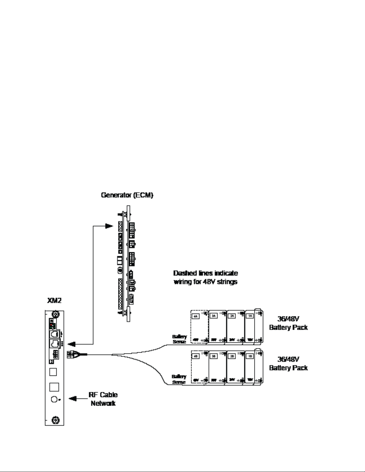
1.1 System Overview
The IDH3 Transponder obtains data from the EDSM (Enhanced Digital Status Monitoring)
interface card through an XM2 Power Supply. The EDSM collects data directly from the
battery strings or from the AlphaBus Communications Network, depending on system
confi guration.
Equipment monitored (direct battery monitoring):
• An XM2 Power Supply
• One or two 36Vdc or 48Vdc battery strings
• One AlphaGen stationary generator system (if installed)
Battery Wire Sense
Harness
Fig. 1-2, System Interconnection Diagram 1
8
745-420-B0-001 Rev. A
Page 9
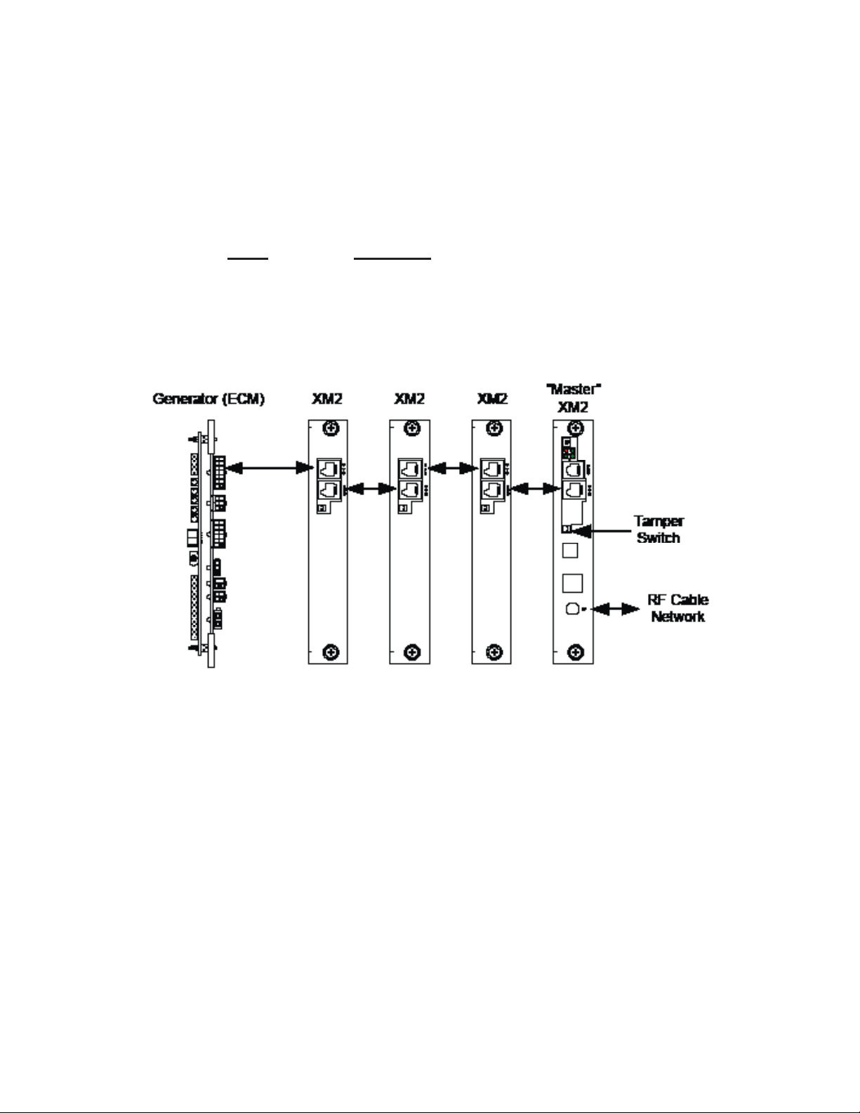
1.0 Introduction to the DOCSIS® Transponder, continued
1.1 System Overview, continued
Equipment monitored via the AlphaGuard™:
The AlphaGuard performs electrical compensation for differences in individual batteries in
the string. The unit can be confi gured to pass measurements from the battery string to a
status monitoring device (EDSM card, DOCSIS transponder, etc.) via an interface cable.
Model Description
AG-CMT-3SC AlphaGuard manages 3 batteries*
AG-CMT-4SC AlphaGuard manages 4 batteries*
* Includes 6’ battery cables
745-420-B0-001 Rev. A
Fig. 1-3, System Interconnection Diagram 2
9
Page 10

1.0 Introduction to the DOCSIS® Transponder, continued
1.2 LED Indicators
Communication State HMS RDY Tx Rx
Transponder Initializing OFF and ON OFF and ON OFF and ON OFF and ON
Searching for DOCSIS Downstream Channel OFF OFF and ON OFF OFF and ON
DOCSIS Channel Locked;
Establishing Upstream IP Connectivity
IP Connectivity Established; Registering with CMTS OFF OFF and ON ON ON
Registration Complete OFF and ON OFF and ON ON ON
OFF OFF and ON OFF and ON ON
10
745-420-B0-001 Rev. A
Page 11

2.0 Transponder Installation
Steps to a Successful Installation:
• Operator’s IT Department must allow the transponder’s Cable Modem (CM) to obtain an IP
address from the DHCP Server.
• Operator’s IT Department must provision the transponder, as described in the following section.
• Operator’s network security policies must allow SNMP traffi c to pass between transponder and
SNMP manager.
• Install the transponder and any related equipment in the power supply.
• Connect an RF drop.
• Verify proper operation.
2.1 Provisioning the Transponders in the Network
Before installing transponders, the transponders must be provisioned in the network for the
network to recognize, discover, and communicate with them when they are powered up. The
following graphic shows a typical network.
2.1.1 Network Connectivity
NOTE:
Some provisioning systems require that the transponder’s MAC address be added to the provisioning server
prior to installing the transponder to achieve full functionality.
Customers
Amplifier
Tap
DOCSIS Cable Modem
Configuration File
Power
Supply
PS
Fiber N ode
HFC
NETWORK
IDH3
Transponder
FIBER
CMTS
DOCSIS Cable Modem
Firmware Image Upgrade File
SNMP
Manager
IP
Network
Web Client
Time of Day Server
Provisioning Server
TFTP S er ver
745-420-B0-001 Rev. A
11
Page 12

2.0 Transponder Installation, continued
2.1 Provisioning the Transponder, continued
2.1.2 Transponder Confi guration
Many SNMP Management Applications require an SNMP Trap to be sent from the
transponder for self-discovery and for alarm notifi cations. An SNMP Trap destination
address can be specifi ed to the IDH3 through the DOCSIS confi guration fi les
docsDevNmAccessTable (RFC 2669).
12
745-420-B0-001 Rev. A
Page 13

2.0 Transponder Installation, continued
2.2 Verifying Firmware Version and Device Address
Before removing the Inverter Module (IM), verify the power supply fi rmware version and
device address are correct.
• IM fi rmware v3.00.0 is the minimum version compatible with the DOCSIS Embedded
Transponder.
• The power supply device address must not be set to zero, and no two power supplies
monitored by a single transponder may have the same address.
1. Press the Enter key on the inverter module twice to access the SETUP Menu.
2. Press the Down key until CODE VER is displayed.
3. Verify that the fi rmware code is 3.00.0 or higher.
4. Press the Down key twice until DEVICE ADDRESS is displayed.
5. If the address is correct (and not zero), skip to Step 10.
6. To change the address, press the Enter key to enter the Edit mode.
7. Press the Up or Down key until the desired address (between 1 and 7) is displayed.
Remember that each power supply on a single transponder must have a unique address.
8. Press the Enter key to load the new address.
9. Press the Enter key again to accept the new data.
10. Press ESC three times to return to the OPERATION NORMAL screen.
2.3 Installing the Transponder Hardware
The Embedded Transponder is static sensitive. An ESD wrist strap should be worn when installing
the transponder.
Tools Required: #1 Phillips Screwdriver
1. Move the XM2 Battery Breaker to the OFF position.
2. Unplug all connections to the front of the Inverter Module (battery cable, RTS, etc).
3. Loosen the thumbscrews holding the Inverter Module into the power supply. Slide the
Inverter Module out just enough to disconnect the ribbon cable. Now slide the Inverter
Module out of the power supply.
To reduce the risk of electric shock, completely remove the Inverter Module from the Power
Supply prior to installation.
745-420-B0-001 Rev. A
13
Page 14

2.0 Transponder Installation, continued
2.3 Installing the Transponder Hardware, continued
4. Attach the new transponder ribbon cable supplied to the 10-pin connector on the
transponder. The connectors are keyed to prevent incorrect orientation.
5. Attach the plastic standoff to the transponder PC board as shown in Fig 2-1
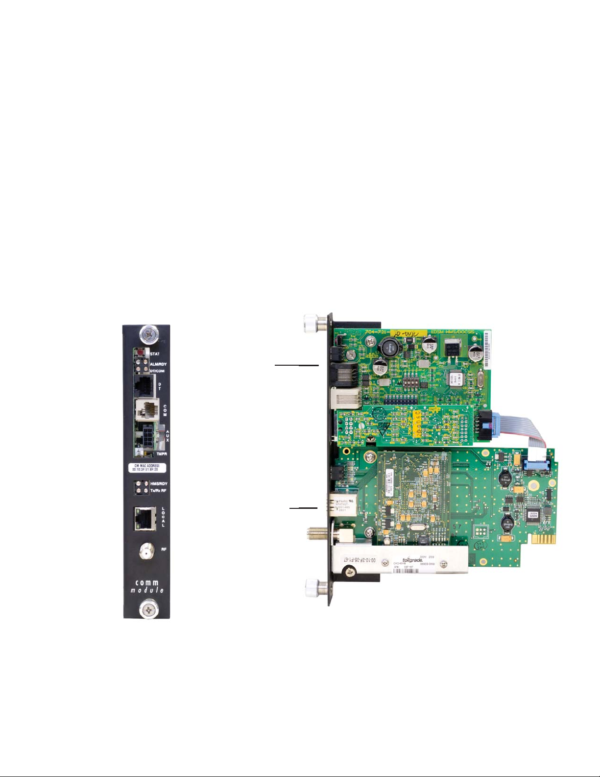
6. Verify that the MAC address label is installed on the transponder. If the label is missing,
locate the label in the packaging and apply to the transponder as shown in Fig 2-2.
7. Place the transponder as shown in Fig 2-2 below. The RF connector must be inserted
through the front of the Comm Module bracket.
8. Press the standoff into the Inverter Module chassis.
9. Secure the transponder to the Comm Module Bracket with the two screws provided.
10. Connect the transponder ribbon cable to the EDSM. Note the 90o twist in the cable.
11. Reconnect the Inverter Module ribbon cable, and reinstall the Inverter Module into the
power supply.
12. Reconnect all the cables unplugged in Step 2 .
13. Move the Battery Breaker to the ON position.
Fig. 2-1, Attaching the PCB Standoff
IDH3 COMPONENTS
These two screws attach the transponder to the
1
Communications Module bracket.
2
Transponder ribbon cable connector
3
Location of PCB standoff
4
Transponder MAC address labels
Communications Module bracket (attaches to power
5
supply Inverter Module).
6
RF Connector
10-pin Connector
PCB Standoff
4
1
1
6
2
3
14
Fig. 2-2, Transponder Components
5
4
745-420-B0-001 Rev. A
Page 15

2.0 Transponder Installation, continued
2.4 RF Connection
Connect the RF drop to the RF connector on the transponder. The drop must have a properly
installed ground block in or on the power supply enclosure. Recommended forward RF level
is 0 dBmV.
RF Connection
Ground Surge
Protector
(User Provided)
RF Cable
to Headend
See Caution Below
Fig. 2-3, RF Connection with Ground Block
Alpha requires installing a grounded surge suppressor (Alpha P/N 162-028-10 or equivalent).
2.5 Verifying Transponder Operation
The LED behavior per the table below shows the status of LEDs during transponder
operation:
Communication State HMS RDY Tx Rx
Transponder Initializing OFF and ON OFF and ON OFF and ON OFF and ON
Searching for DOCSIS Downstream Channel OFF OFF and ON OFF OFF and ON
DOCSIS Channel Locked;
Establishing Upstream IP Connectivity
IP Connectivity Established; Registering with CMTS OFF OFF and ON ON ON
Registration Complete OFF and ON OFF and ON ON ON
OFF OFF and ON OFF and ON ON
745-420-B0-001 Rev. A
15
Page 16

3.0 Network/Element Management Software
3.1 Provisioning the SNMP Manager
The following MIB (Management Information Base) fi les are required for the SNMP Manager
to collect data from the transponders. These fi les can be found on the Society of Cable
Telecommunications (SCTE) web site www.scte.org. There are dependencies between MIB
fi les so they should be compiled in the following order listed below:
ANSI/SCTE 36 2002R2007 (formerly HMS 028), SCTE-ROOT Management Information
Base (MIB) Defi nitions
ANSI/SCTE 37 2008 (formerly HMS 072), Hybrid Fiber/Coax Outside Plant Status Monitoring
SCTE-HMS-ROOTS Management Information Base (MIB) Defi nition
ANSI/SCTE 38-1 2009 (formerly HMS 026), Hybrid Fiber/Coax Outside Plant Status
Monitoring SCTE-HMS-PROPERTY-MIB Management Information Base (MIB) Defi nition
ANSI/SCTE 38-2 2005 (formerly HMS 023), Hybrid Fiber/Coax Outside Plant Status
Monitoring SCTE-HMS-ALARMS-MIB Management Information Base (MIB) Defi nition
ANSI/SCTE 38-3 2008 (formerly HMS 024), Hybrid Fiber/Coax Outside Plant Status
Monitoring SCTE-HMS-COMMON-MIB Management Information Base (MIB) Defi nition
ANSI/SCTE 38-4 2006 (formerly HMS 027), Hybrid Fiber/Coax Outside Plant Status
Monitoring SCTE-HMS-PS-MIB Management Information Base (MIB) Defi nition
ANSI/SCTE 38-6 2006 (formerly HMS 033) Hybrid Fiber/Coax Outside Plant Status
Monitoring - SCTE-HMS-GEN-MIB Management Information Base (MIB) Defi nition
ANSI/SCTE 38-7 2008 (formerly HMS 050), Hybrid Fiber/Coax Outside Plant Status
Monitoring SCTE-HMS-Transponder-Interface-Bus(TIB)-MIB Management Information Base
(MIB) Defi nition
16
745-420-B0-001 Rev. A
Page 17

4.0 Using the Ethernet (Craft) Port
4.1 IDH3 Web Interface
4.1.1 Overview
A web interface is available on the IDH3 transponder. The default port for HTTP
traffi c is port 80, but can be confi gured to use other ports via the Tollgrade httpMgmt
MIB. HTTP port confi guration is available for the cable modem interface (via the
cable modem IP address) and the CPE interface (via the Local connection). The
Local connection’s IP address is 192.168.100.1, and may be easily accessed by
using a standard CAT5 patch cord between a computer and the ETHERNET port on
the front of the transponder.
The interface can be accessed by typing the cable modem IP address of the
transponder into your web browser. The interface includes status data for the cable
modem, the HMS transponder, High Speed Internet Access (HSIA) diagnostics, the
RF constellation page and equalizer page, and the MTA (Media Terminal Adapter) in
VoIP systems.
745-420-B0-001 Rev. A
17
Page 18

4.0 Using the Ethernet (Craft) Port, continued
4.1 IDH3 Web Interface, continued
4.1.1 System Overview, continued
Depending on the network confi guration of the computer you are using to connect to
the IDH3 transponder, it may be necessary to set the network interface to a temporary static IP address. This will make itself known if you can’t bring up the fi rst web
page using 192.168.100.1. Here’s how to resolve that issue, and connect to the
transponder:
Click on the “start” button (lower left button on most Windows computers). When
the window pops up, right-click on “Network” (usually about half the way down the
second column).
Click on the bottom option, “Properties,” and right-click on the network interface you
are using. You’ll see a dialog box much like the one below; scroll down to the entry
“Internet Protocol (TCP/IP)” and then click on “Properties.”
18
745-420-B0-001 Rev. A
Page 19

4.0 Using the Ethernet (Craft) Port, continued
4.1 IDH3 Web Interface, continued
4.1.1 System Overview, continued
You’ll see another dialog box, and enter the values as they appear in the diagram
below:
745-420-B0-001 Rev. A
Click on “OK” and try to connect to the transponder once again using 192.168.100.1
in your Web browser.
19
Page 20

4.0 Using the Ethernet (Craft) Port, continued
4.1 IDH3 Web Interface, continued
4.1.1 System Overview, continued
NOTE:
The IDH3 web pages do not automatically refresh, so the user must manually reload each one to view the
most current data.
Confi guring the sysName and sysLocation OIDs
It is also possible to confi gure the sysName (1.3.6.1.2.1.1.5.0) and sysLocation
(1.3.6.1.2.1.1.6.0) OIDs from the web interface. This feature is password protected.
There are both Admin and User usernames and passwords. Both usernames (Admin
and User) have the authority to set sysName and sysLocation. The passwords can
be changed via the Broadcom httpMgmt MIB. The specifi c OIDs and default values
are shown below.
Table 5. OIDs for Usernames and Passwords for Web Interface Access
Parameter OID Default
httpAdminId 1.3.6.1.4.1.4413.2.2.2.1.1.3.1.0 edarglloT
httpAdminPassword 1.3.6.1.4.1.4413.2.2.2.1.1.3.2.0 aDm1n$TR8r
httpUserId 1.3.6.1.4.1.4413.2.2.2.1.1.3.3.0 Tollgrade
httpUserPassword 1.3.6.1.4.1.4413.2.2.2.1.1.3.4.0 Tollgrade
It is possible to change the port number for Web Access and to disable it entirely.
The table below lists the Parameters, OIDs, and default settings. Setting the Port
value to sero (0) will disable access to the HTTP server for the given interface. The
specifi c OIDs and their default values are listen in Table 6. The port must be open to
use all of the deatures described in the following sections.
Table 6. OIDs for Port Management
Parameter OID Default
httpCMMgmtPort 1.3.6.1.4.1.2082.5.5.1.1.1.0 80
httpCPEMgmtPort 1.3.6.1.4.1.2082.5.5.1.1.2.0 80
20
745-420-B0-001 Rev. A
Page 21

4.0 Using the Ethernet (Craft) Port, continued
4.1 IDH3 Web Interface, continued
4.1.2 Status Page for Firmware Information
This homepage provides details on the fi rmware running in the cable modem and al-
lows navigation to other diagnostic information via the links provided..
745-420-B0-001 Rev. A
Fig. 4-1, Status Page for Firmware Information
21
Page 22

4.0 Using the Ethernet (Craft) Port, continued
4.1 IDH3 Web Interface, continued
4.1.3 Status Page for Connection Information
This page provides detailed status information related to the current connection to the
CMTS.
22
Fig. 4-2, Status Page for Connection Information
745-420-B0-001 Rev. A
Page 23

4.0 Using the Ethernet (Craft) Port, continued
4.1 IDH3 Web Interface, continued
4.1.4 Status Page for the SNMP Event Log
This page provides recent event log entries.
745-420-B0-001 Rev. A
Fig. 4-3, Status Page for the SNMP Event Log
23
Page 24

4.0 Using the Ethernet (Craft) Port, continued
4.1 IDH3 Web Interface, continued
4.1.5 HMS Power Supply Data Page
This page displays HMS power supply, generator, and generic I/O data.
The coloring of an individual parameter indicates its alarm level as follows:
· Light grey: Parameter is not in alarm.
· Yellow: Parameter is in minor alarm.
· Red: Parameter is in major alarm.
24
Fig. 4-4, HMS Power Supply Data Page
745-420-B0-001 Rev. A
Page 25

4.0 Using the Ethernet (Craft) Port, continued
4.1 IDH3 Web Interface, continued
4.1.6 Generator Data Page
Click on the GEN8 link to see the Generator data page.
745-420-B0-001 Rev. A
Fig. 4-5, Generator Data Page
25
Page 26

5.0 Specifi cations
Power Supplies Supported: XM2-HP, XM2
DOCSIS Compatibility: DOCSIS 1.1, 2.0
Monitoring Protocol: SNMP v1
Devices Monitored:
Power Supply, Batteries and Generator
(compatible with ANSI/SCTE 25-3 2002,
formerly HMS 022)
Hardware
RF Cable Interface: F-connector, female, 75Ohm
Local Interface:
LED Indicators:
Ethernet interface for direct web page
access to diagnostic information.
Transponder Ready/RF Link Established
Transponder/CMTS Communications
Power Supply/Transponder
Communication
Environmental
Operating Temperature: -40 to 65°C / -40 to 149°F
Humidity: 10 to 90% non-condensing
EN50022 Class A and FCC Part 15
Emissions:
Class A
(Installed in power supply enclosure
system)
RF Transmit/Receive
Tx Frequency Range: 5 to 42MHz
Output Power: 8 to 58dBmV
Channel Bandwidth: 6MHz
Receive Center
Frequency Range:
Input Level: -15 to 15dBmV
91 to 857MHz (Standard, HRC, IRC
channels)
Power Supply Monitored Parameters
Major Alarm:
Minor Alarm:
Input Line Voltage: 90 to 270Vac 50/60Hz measured value
Output Voltage: 60/90Vac measured value
Output Current 1: 0 to 25A measured value
Output Current 2, 3, 4:
Output Power: Calculated, reported in AC Watts
UPS Status:
Enclosure Door: Open/Closed
Battery Voltage:
Battery Temperature: Measured, reported in Celsius
Remote Test Control: Start/Stop XM2 self test cycle
Logical (OR) of: test fail, battery fail, line
isolation alarm, output overload, inverter
over temperature, N+1 active, fuse fail
Logical (OR) of: temperature probe error,
AC line loss, N+1 error
0 to 25A measured value (if optional ports
installed)
AC line, Standby, Test in-process, Test
alarm
6 or 12V batteries, up to 4 battery strings
Individual battery voltages measured
reported to ±100mv resolution
Generator Monitored Parameters
Status: Engine off, running, alarm
Aggregate alarm consisting of: low oil
Generator Alarm:
Gas Hazard: OK, Alarm
Water Intrusion: OK, Alarm
Pad Shear: OK, Alarm
Enclosure Door: Open, Alarm
Ignition Battery Voltage: 10.2 to 15.5Vdc, 100mV resolution
Enclosure Temperature: -40 to 100°C / -40 to 212°F
Low Fuel: OK, Alarm
Remote Test: Start and Stop control input
pressure, engine over-temp, engine overspeed, crank limit, over voltage, low fuel,
water intrusion, pad shear, gas hazard,
test fail
26
745-420-B0-001 Rev. A
Page 27

6.0 Acronym Defi nitions
ANSI: American National Standards Institute
CM: Cable Modem
CMTS: Cable Modem Termination System
DHCP: Dynamic Host Confi guration Protocol
DOCSIS: Data Over Cable Service Interface Specifi cation
EDSM: Enhanced Digital Status Module
EMS: Element Management System
IT: Information Technology
MAC: Media Access Control
MIB: Management Information Base
NMS: Network Management System
QoS: Quality of Service
SCTE-HMS: Society of Cable Telecommunications Engineers-Hybrid Management Sublayer
SI: Serial Interface
SNMP: Simple Network Management Protocol
TFTP: Trivial File Transfer Protocol
TOD: Time of Day
UDP: User Datagram Protocol
VoIP: Voice over Internet Protocol
745-420-B0-001 Rev. A
27
Page 28

Page 29

Alpha Technologies
Power
Alpha Technologies
3767 Alpha Way
Bellingham, WA 98226
USA
Tel: +1 360 647 2360
Fax: +1 360 671 4936
Web: www.alpha.com
Alpha Technologies Ltd.
4084 McConnell Court
Burnaby, BC, V5A 3N7
CANADA
Tel: +1 604 430 1476
Fax: +1 604 430 8908
Alpha Technologies
Europe Ltd.
Twyford House Thorley
Bishop's Stortford
Hertfordshire CM22 7PA
UNITED KINGDOM
Tel: +44 0 1279 501110
Fax: +44 1 279 659870
Alpha Technologies GmbH
Hansastrasse 8
D 91126 Schwabach
GERMANY
Tel: +49 9122 79889 0
Fax: +49 9122 79889 21
Alphatec, Ltd
339 St. Andrews Street
Suite 101 Andrea Chambers
3307 Limassol
CYPRUS
Tel: +357 25 375675
Fax: +357 25 359595
AlphaTEK ooo
Khokhlovskiy Pereulok 16
Stroenie 1 Offi ce 403
109028 Moscow
RUSSIA
Tel: +7 495 916 1854
Fax: +7 495 916 1349
Alphatec Baltic
S. Konarskio Street G.49-201
Vilnius LT-03123
LITHUANIA
Tel: +370 5 210 5291
Fax: +370 5 210 5292
Alpha Technologies
34, Grande Rue
Bétheny, F-51450
France
Phone: +33 32 64990 54
Fax: +33 67 54289 44
Copyright © 2010 Alpha Technologies, Inc. All rights reserved. Alpha is a registered trademark of Alpha Technologies. 745-420-B0-001 Rev. A.
Due to continuing product improvements, Alpha reserves the right to change specifi cations without notice.
 Loading...