

Page 1

FMPS
FTTP Multipurpose Power Supply
010-592-B2
The following documents and drawings are included in this manual to provide the necessa ry information required for
installation, operation and fault diagnosis of the unit:
• Specifications: 010-592-B1
• Important Safety and Installation Instructions: 010-592-C0
• Warranty and Service Information: 048-700-10
• Service Centers: 048-693-10
Argus Technologies Ltd. 010-592-B2 Rev A WC
Printed in Canada. © 2008 Argus Technologies Ltd. ARGUS is a registered trademark of Argus Technologies Ltd. All Rights Reserved.
Page 2

Specifications for Argus Technologies’ FMPS
Input
Voltage (nominal): 120Vac @ 2.5A; 240Vac @ 1.25A
Frequency: 50/60Hz
Current (maximum): 2.5A @120Vac (maximum DC output + charger + heater)
Inrush Current: 4.1A maximum (peak value)
Surge Protection: ANSI/IEEE Std. C62.41 to Category A, B, or C requirements,
using a “Ring Wave” or “Combination” waveform, at a level of 6kV
Output
Power: 150W continuous; 170W, 10 second maximum
Voltage (nominal): 55Vdc
Current: 3.1A typical (crowbar limited beyond 4A DC)
Short Circuit: 5A
Loading: Following GR-909 telephone lines in various states; e.g., ringing, off-hook, on-
hook, data, and video operation requirements
Ripple: < 3mV
Noise: < 100mV
In accordance with FCC requirements, we provide the following statement as specified in the FCC guidelines for
conformance to Part 15, Class B:
NOTE: This equipment has been tested and found to comply with the limits for a Cla ss B digital
device, pursuant to part 15 of the FCC Rules. These limits are designed to provide reasonable
protection against harmful interference in a residential installation. This equipment generates,
uses, and can radiate radio frequency energy and, if not installed and used in accordan ce with
the instructions, may cause harmful interference to radio communication s. However, there is no
guarantee that interference will not occur in a particular installation. If this equipment does cause
harmful interference to radio or television reception, which can be determined by turning the
equipment off and on, the user is encouraged to try to correct the interference by one or more of
the following measures:
• Reorient or relocate the receiving antenna.
• Increase the separation between the equipment and receiver.
• Connect the equipment into an outlet on a circuit different from that to which the receiver is
connected.
• Consult the dealer or an experienced radio/TV technician for help.
Any changes or modifications to this equipment not expressly described in this manual could void the FCC
compliance.
RMS
p-p
Argus Technologies Ltd. 010-592-B1 Rev A WC
Printed in Canada. © 2008 Argus Technologies Ltd. ARGUS is a registered trademark of Argus Technologies Ltd. All Rights Reserved. Page 1 of 5
Page 3

Specifications for Argus Technologies’ FMPS Continued
Local Alarms
System LED: Green stea dy = system output normal, DC output/off = no AC or battery power
Battery LED: Yellow steady = system on battery/off = normal mode
Replace Battery: Red steady = replace one or two battery strings/off = batteries within parameters
Replace Battery A&B (internal): Red steady = replace one or both battery strings/off = batteries within parameters
Audible Indicator (Alarm On): Alarm enable/disable toggle switch located on FMPS, batteries below voltage
parameters
Remote Alarms
SEE ALSO CONNECTIONS
Pin 1 Alarm Return: Open collector return reference
Pin 2 AC Fail: On battery
Pin 3 Replace Battery: One or both battery strings failed periodic self-test
Pin 4 Missing Battery: < 8 batteries
Pin 5 Battery Low: Battery string voltage < 46.8Vdc
Connections
Output: 2x terminal blocks accepting #16 AWG (1.5mm²), parallel connections
Remote Alarms: 2x 5-position IDC #24 AWG (0.25mm²), parallel connections
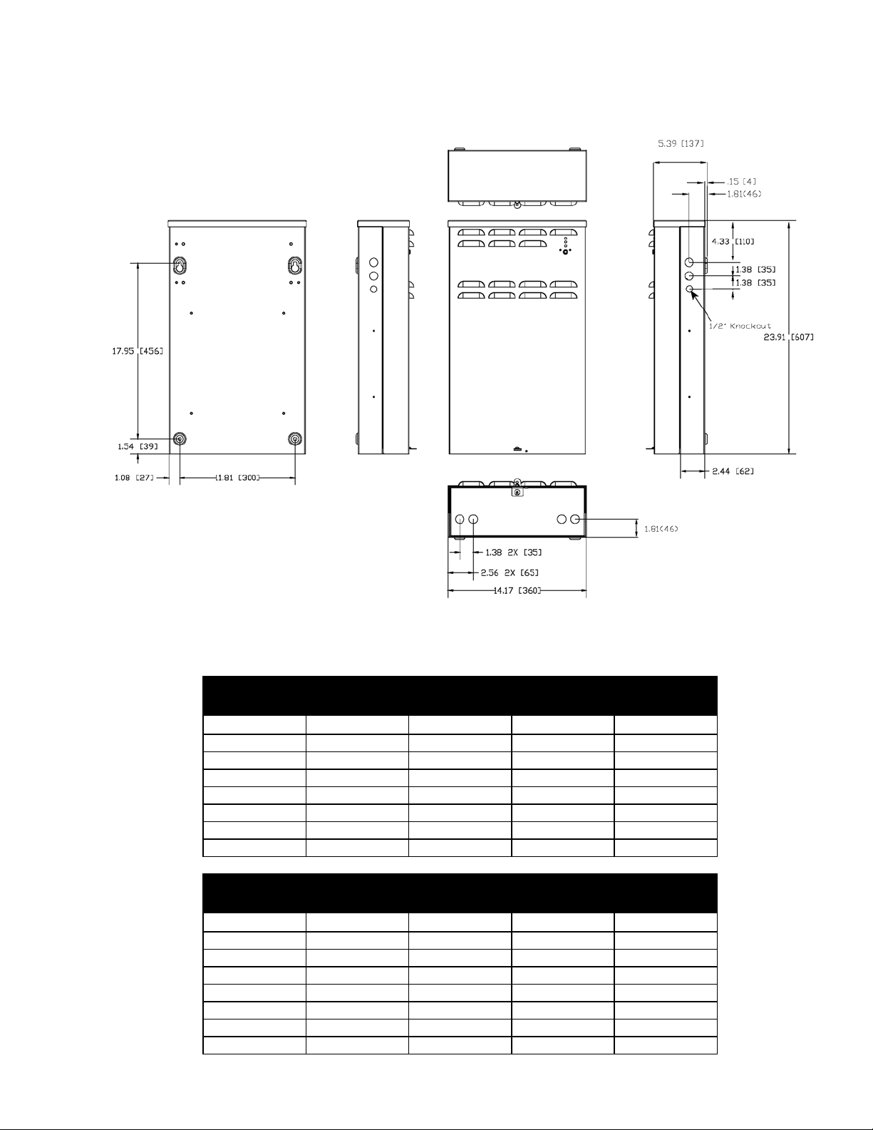
Mechanical
Dimensions
FMPS: 603mm H x 356mm W x 140mm D
FMPS + Shipping Carton: 724mm H x 432mm W x 298mm D
Weight
FMPS: 11.3 kg
FMPS + Shipping Carton: 13.6 kg
Battery
Type: 4 or 8 7.2AH valve regulated lead acid (VRLA)
Model: GS Battery Inc., OEM P/N: PX12072F2-HG
(23.75” H x 14” W x 5.5” D)
(28.5” H x 17” W x 11.75” D)
(25 lb.)
(30 lb.)
CSB, OEM P/N: GP1272F2
For compatibility with other battery models, please consult Argus factory.
Argus Technologies Ltd. 010-592-B1 Rev A WC
Printed in Canada. © 2008 Argus Technologies Ltd. ARGUS is a registered trademark of Argus Technologies Ltd. All Rights Reserved. Page 2 of 5
Page 4

Specifications for Argus Technologies’ FMPS Continued
Environmental
Operating Temperature: -10 to 46.1°C plus solar loading
(14 to 115°F)
[-40° with cold weather kit (includes heater)]
Storage Temperature: -15 to 85°C
(5 to 185°F)
Humidity: 0 to 95% non-condensing
Elevation: 0 to 3048m operating, 15240m storage
(0 to 10000 ft operating, 50000 ft storage)
Compliance
CSA/UL: 60950
EN: 60950
55022 Class B
FCC: Part 15 Class B
Telcordia: GR-63-CORE
GR-1089-CORE
System Configurations
This product is available to order under the following system configurations:
Description Part Number/List Option
FMPS with Verizon silkscreen, heater option, 120Vac line cord ....................................................... 010-592-20-050
FMPS with Alpha silkscreen, heater option, 120Vac line cord .......................................................... 010-592-20-053
FMPS with Alpha silkscreen, heater option, universal IEC line cord................................................. 010-592-20-058
Part Numbers and List Options
This product is available to order with the following options and accessories:
Description Part Number/List Option
FMPS UPS 150W ......................................................................................................................................010-592-20
Basic power module assembly ..........................................................................................................................*List 0
Cool gray with Alpha logo ..................................................................................................................................List 53
Cool gray with Verizon logo ...............................................................................................................................List 58
Cool gray with Motorola logo..............................................................................................................................List 59
Cold weather option...........................................................................................................................................List 80
Line cord, receptacle, 250Vac, IEC 60320 ........................................................................................................List 84
Line cord, 120Vac, 5-15P...................................................................................................................................List 85
Fittings, liquid tight .............................................................................................................................................List 86
* Default options
Kit, battery cables, 100 sets, FMPS 150W ................................................................................................037-116-20
Kit, fittings, 50 sets, FMPS 150W ..............................................................................................................037-117-20
The above information is valid at the time of publication. Consult factory for up-to-date ordering information.
Specifications are subject to change without notice.
Argus Technologies Ltd. 010-592-B1 Rev A WC
Printed in Canada. © 2008 Argus Technologies Ltd. ARGUS is a registered trademark of Argus Technologies Ltd. All Rights Reserved. Page 3 of 5
Page 5
Specifications for Argus Technologies’ FMPS Continued
Dimensions
Battery Run Times
ONE STRING
Run Time (hours) vs. Temperature
Watts -10°C 0°C 25°C 40°C
20
40
60
80
100
120
150
Watts -10°C 0°C 25°C 40°C
20
40
60
80
100
120
150
14.4 15.6 18.7 20.0
7.0 7.4 8.9 10.0
3.9 4.8 6.6 7.2
2.7 3.1 4.3 5.5
2.2 2.5 3.2 3.7
1.8 1.9 2.6 2.9
1.5 1.7 2.0 2.3
TWO STRINGS
Run Time (hours) vs. Temperature
21.7 22.5 24.4 25.0
14.1 15.6 18.7 20.0
9.0 9.6 13.1 15.5
6.7 7.4 8.9 10.0
5.9 6.3 7.5 7.9
3.7 4.8 6.7 7.2
3.0 3.3 5.0 6.2
Argus Technologies Ltd. 010-592-B1 Rev A WC
Printed in Canada. © 2008 Argus Technologies Ltd. ARGUS is a registered trademark of Argus Technologies Ltd. All Rights Reserved. Page 4 of 5
Page 6
Specifications for Argus Technologies’ FMPS Continued
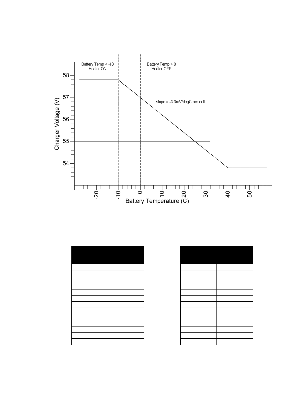
Temperature Compensation
Battery temperature compensation (charge voltage vs. temperature)
Battery Recharge Times
Battery Recharge vs. Load
90% Recharge Efficiency 90% Recharge Efficiency
Load (W) Hours Load (W) Hours
Power, Single String
5 3.5 5 10.8
10 3.5 10 11.1
15 3.5 15 12.0
20 3.5 20 12.7
25 3.5 25 13.6
30 3.5 30 14.2
40 3.5 40 15.8
50 3.5 50 17.4
75 5.4 75 21.4
100 8.3 100 25.2
125 17.1 125 29.3
150 No recharge 150 No recharge
Battery Recharge vs. Load
Power, Two Strings
Argus Technologies Ltd. 010-592-B1 Rev A WC
Printed in Canada. © 2008 Argus Technologies Ltd. ARGUS is a registered trademark of Argus Technologies Ltd. All Rights Reserved. Page 5 of 5
Page 7

SAFETY NOTES
SAVE THESE INSTRUCTIONS
Review the drawings and illustrations contained in this manual before proceeding. If there are any question s
regarding the safe installation or operation of the system, contact Argus Technologie s or you r nearest Arg us
representative. Save this document for future reference.
To reduce the risk of injury or death, and to ensure the continued safe operation of this product, the following
notations/symbols have been placed throughout this manual. Where these notations/symbols appear, use e x tra
care and attention.
ATTENTION:
The use of ATTENTION indicates specific regulatory/code requirements that may affect the
placement of equipment and installation procedures.
NOTE: A NOTE provides additional information to help complete a specific task or procedure.
CAUTION!
The use of CAUTION indicates safety information intended to PREVENT DAMAGE to material or
equipment.
WARNING!
A WARNING presents safety information to PREVENT INJURY OR DEATH to the technician or
user.
i
Page 8

General Safety Precautions
To avoid injury:
• Read and follow all installation, equipment grounding, usage, and service instructions included in this manual.
• Disconnect power before servicing.
• This enclosure and its associated hardware must be serviced only by authorized personnel.
• Enclosure must remain locked at all times, except when authorized service personnel are present.
• Remove all conductive jewelry or personal equipment prior to servicing equipment, parts, connectors, wiring,
or batteries.
• Use proper lifting techniques whenever handling enclosure, equipment, parts, or batteries.
• Batteries contain dangerous voltages, currents and corrosive material. Battery installation, maintenance,
service and replacement must be performed by authorized personnel only.
• Never use uninsulated tools or other conductive materials when installing, maintaining, servicing or replacing
batteries.
• Use special caution when connecting or adjusting battery cabling. An improperly conne cted battery cable or
an unconnected battery cable can result in arcing, a fire, or possible explosion.
• A battery that shows signs of cracking, leaking or swelling must be replaced immediately by authorized
personnel using a battery of identical type and rating.
• Avoid any contact with gelled or liquid emissions from a valve-regulated lead-acid (VRLA) b attery. Emissions
contain dilute sulfuric acid which is harmful to the skin and eyes. Emissions are electrolytic, which are
electrically conductive and are corrosive. Follow the Chemical Hazards notes if contact occurs.
• Do not smoke or introduce sparks in the vicinity of a battery.
• Under certain overcharging conditions, lead-acid batteries can vent a mixture of hydrogen gas that is
explosive. Proper venting of the enclosure is required.
• Follow the battery manufacturer’s approved transportation and storage instructions.
CAUTION!
Enclosure, equipment, or parts may be damaged (or cause damage) if installed or used improperly.
To avoid damage:
• Prior to installation, verify that the AC input voltage to the enclosure and its equipment match with respect to
voltage and frequency.
• Prior to installation, verify that the output voltage from the enclosure or its equipment match the voltage
requirements of the connected equipment (load).
• Prior to installation, verify that the enclosure’s utility service panel is equipped with a properly rated circuit
breaker for use with the equipment inside. Refer to manufacturer’s recommend ations.
• Review and upgrade utility service panel circuit breaker requirements whenever the equipment within the
enclosure is changed.
• Prior to installation, contact local utilities, local building maintenance departments, and cable/piping locator
services to ensure that installation does not interfere with existing utility or building cables/piping.
• Do not exceed the output rating of equipment. Verify load requirements prior and during connection process.
• Prior to handling the batteries, touch a grounded metal object to dissipate any static charge that may have
developed in your body.
• For continued protection against risk of fire, replace only with same type and rating of fuse.
ii
Page 9

Battery Safety Notes
WARNING!
Lead-acid batteries contain dangerous voltages, currents and corrosive material. Battery
installation, maintenance, service and replacement must be performed only by authorized
personnel.
Chemical Hazards
Any gelled or liquid emissions from a valve-regulated lead-acid (VRLA) battery contain dilute sulfuric acid, which
is harmful to the skin and eyes. Emissions are electrolytic, and are electrically conductive and corrosive.
To avoid injury:
• Servicing and connection of batteries shall be performed by, or under the direct supervision of, personnel
knowledgeable of batteries and the required safety precautions.
• Always wear eye protection, rubber gloves, and a protective vest when working near batteries. Remove all
metallic objects from hands and neck.
• Batteries produce explosive gases. Keep all open flames and sparks away from batteries.
• Use tools with insulated handles; do not rest any tools on top of batteries.
• Batteries contain or emit chemicals known to the State of California to cause cancer and birth defects or other
reproductive harm. Battery post terminals and related accessories contain lead and lead compounds. Wash
hands after handling (California Proposition 65).
• Wear protective clothing (insulated gloves, eye protection, etc.) whenever installing, maintaining, servicing, or
replacing batteries.
• If any battery emission contacts the skin, wash immediately and thoroughly with water. Follow your
company’s approved chemical exposure procedures.
• Neutralize any spilled battery emission with the special solution contained in an approved spill kit or with a
solution of 2.2 kg (one pound) bicarbonate of soda to 3.8 liters (one gallon) of water. Report chemical spill
using your company’s spill reporting structure and seek medical attention if necessary.
• Never use uninsulated tools or other conductive materials when installing, maintaining, servicing or replacing
batteries.
• Use special caution when connecting or adjusting battery cabling. An improperly conne cted battery cable or
an unconnected battery cable can make contact with an unintended surface that can result in arcing, fire, or
possible explosion.
• A battery showing signs of cracking, leaking, or swelling should be replaced immediately by authorized
personnel using a battery of identical type and rating.
iii
Page 10

Battery Maintenance Guidelines
The battery maintenance instructions listed below are for reference only. Battery manufacturer’s instructions for
transportation, installation, storage or maintenance take precedence over these instructions.
• To prevent damage, inspect batteries every three months for:
Signs of battery cracking, leaking or swelling.
personnel using a battery of the identical type and rating.
Signs of battery cable damage.
using replacement parts specified by vendor.
Loose battery connection hardware.
and connection hardware for the application.
• Apply battery manufacturer’s specified antioxidant compound on all exposed connections.
• Verify battery terminals or exposed connection hardware is not within close proximity of a conductive surface.
Reposition batteries as necessary to maintain adequate clearance.
• Clean up any electrolyte (battery emission) in accordance with all federal, provincial (or state), and local
regulations or codes.
• Proper venting of the enclosure is recommended. Follow the battery manufacturer’s approved transportation
and storage instructions.
• Always replace batteries with those of an identical type and rating. Never install old or untested batteries.
• Do not charge batteries in a sealed container. Each individual battery should have at least 12.7mm (0.5”) of
space between it and all surrounding surfaces to allow for convection cooling.
• All battery compartments must have adequate ventilation to prevent an accumulation of potentially dangerous
gas.
Battery cable should be replaced immediately by authorized personnel
Refer to battery manufacturer’s documentation for the correct torque
The battery should be replaced immediately by authorized
Recycling and Disposal Instructions
Spent or damaged batteries are considered environmentally unsafe. Always recycle used batteries or dispose of
the batteries in accordance with all federal, provincial (or state) and local regulations.
Electrical Safety
• Lethal voltages are present within the power system. Never assume that an electrical connection or conductor
is not energized. Check the circuit with a voltmeter with respect to the grounded portion of the enclosure (both
AC and DC) prior to any installation or removal procedure.
• Always use the buddy system when working under hazardous conditions.
• A licensed electrician is required to install permanently wired equipment.
• Ensure no liquids or wet clothes contact internal components.
• Hazardous electrically live parts inside this unit are energized from batteries even when the AC input powe r is
disconnected.
• For cord connected model, the plug is the disconnect device. A socket outlet shall be installed near the
equipment. For hardwired model, a breaker shall be used for a disconnect device. For IEC line cord option,
the inlet on the cord is the disconnect device for such systems.
CAUTION!
DOUBLE POLE/NEUTRAL FUSING:
For continued protection against risk of fire, replace only with the same type and rating of fuse.
iv
Page 11

Grounding Connection Notes
In order to provide a ready, reliable source of backup power it is necessary to establish a grounding system that
not only provides for the safety of the service personnel responsible for its operation and maintenance, but also
facilitates the proper operation and protection of the equipment within the network. Such a grounding system will
provide protection with respect to operator safety, system communication, and equipment protection.
Safety Ground
The safety ground is a two-part system. The first part is a return path for stray current back to the input breaker,
and the second is a return path from the enclosure to a second ground rod.
Typically, the safety, or utility ground, provides a return path to the input breaker or fuse panel by means of a
connection to an appropriate driven ground rod at the base of the power pole. This path must meet National
Electrical Code (NEC) as well as local codes to ensure the breaker will open, preventing unwanted current flow
from posing a hazard to service personnel.
Strike (Lightning) Ground
Lightning strikes, grid switching, or other aberrations on the power line all have the potential to cause “fast risetime currents” which can cause damage to the powering system. Without a low-impedance path to ground, the
current, while travelling through wires of varying impedance, can produce high voltages that will damage the
powering equipment. The most viable method available to protect the system from damage is to divert these
unwanted “fast rise-time currents” along a low-impedance path to ground. A low-impedance path to ground will
prevent these currents from reaching high voltage levels and posing a threat to equipment. The single-point
grounding system provides a low-impedance path to ground, and the key to its success is the proper b onding of
the ground rods, so the components of the grounding system appear as a single point of uniform impedance.
v
Page 12

NOTE: Argus shall not be held liable for any damage or injury involving its enclosures, power supplies, generators,
batteries, or other hardware if used or operated in any manner or subject to any condition not consistent with its
intended purpose, or is installed or operated in an unapproved manner, or improperly maintained.
vi
Page 13

TABLE OF CONTENTS
SECTION PAGE
1 INTRODUCTION.............................................................................................................................................................1
1.1 Scope of the Manual.....................................................................................................................................1
1.2 Product Overview..........................................................................................................................................1
2 THEORY OF OPERATION ............................................................................................................................................... 3
2.1 Operating States........................................................................................................................................... 3
2.2 Exception States........................................................................................................................................... 4
2.3 Status Signals............................................................................................................................................... 4
3 TRANSPORTATION AND STORAGE .................................................................................................................................5
4 INSTALLATION.............................................................................................................................................................. 6
4.1 Enclosure Preparation...................................................................................................................................6
4.2 Lifting Preparation......................................................................................................................................... 6
4.3 Removing the FMPS Cover..........................................................................................................................7
4.4 Wall-mounting the FMPS..............................................................................................................................7
4.5 Recessed/Stud-mounting the FMPS.............................................................................................................8
4.6 Grounding Connection Notes........................................................................................................................8
4.7 Safety Ground...............................................................................................................................................9
4.8 Strike (Lightning) Ground.............................................................................................................................. 9
4.9 AC Wiring, Optional Power Cords.................................................................................................................9
4.10 AC Wiring, Permanent Connection............................................................................................................. 10
4.11 DC Output And Alarm Wiring......................................................................................................................11
5 BATTERY INSTALLATION.............................................................................................................................................12
5.1 Preparation/Mounting.................................................................................................................................. 12
5.2 Installation of Batteries in Argus Power Systems .......................................................................................12
6 OPERATION................................................................................................................................................................15
6.1 Start-up ....................................................................................................................................................... 15
6.2 Normal Operation........................................................................................................................................15
6.3 Status LEDs................................................................................................................................................15
6.4 Battery String LEDs.....................................................................................................................................15
6.5 AC Fail Alarm..............................................................................................................................................15
6.6 Audible Alarm..............................................................................................................................................16
6.7 Battery Backup Mode.................................................................................................................................. 16
6.8 Charging Mode............................................................................................................................................16
6.9 Battery Management................................................................................................................................... 16
6.10 Battery Self-test...........................................................................................................................................17
7 TEST AND COMMISSIONING (OVERVIEW)......................................................................................................................18
7.1 System ........................................................................................................................................................18
7.2 Battery.........................................................................................................................................................18
7.3 Documentation............................................................................................................................................18
8 MAINTENANCE ...........................................................................................................................................................19
8.1 Using the Enclosure Security Bypass.........................................................................................................19
8.2 Replacing the FMPS...................................................................................................................................20
vii
Page 14

9
APPENDIX A...............................................................................................................................................................21
9.1 Installing the FMPS Power Module as a Stand-alone Unit.........................................................................21
10 APPENDIX B............................................................................................................................................................... 22
10.1 Installing the FMPS Power Module in a 19” or 23” Rack Mount Chassis................................................... 22
11 ARGUS CONVENTIONS................................................................................................................................................ 23
11.1 Numbering System......................................................................................................................................23
11.2 Acronyms and Definitions ...........................................................................................................................23
IGURE PAGE
F
Figure 1–Front perspective view of FMPS-150W............................................................................................................. 1
Figure 2–FMPS features overview with cover removed...................................................................................................2
Figure 3–Lifting the FMPS cover...................................................................................................................................... 7
Figure 4–Sliding the FMPS cover out...............................................................................................................................7
Figure 5–FMPS wall-mounting......................................................................................................................................... 7
Figure 6–Stud-mounting the FMPS.................................................................................................................................. 8
Figure 7–Power cord options............................................................................................................................................9
Figure 8–AC mains connection ......................................................................................................................................10
Figure 9–DC output connections.................................................................................................................................... 11
Figure 10–Connecting the battery pigtails...................................................................................................................... 12
Figure 11–Installing the batteries ...................................................................................................................................13
Figure 12–Battery capacity characteristics.....................................................................................................................16
Figure 13–Battery self-test .............................................................................................................................................17
Figure 14–Security bypass.............................................................................................................................................19
Figure 15–FMPS power module connection details.......................................................................................................21
Figure 16–Location of FMPS mounting bracket screws................................................................................................. 22
Figure 17–Location of mounting bracket captive screw.................................................................................................22
Figure 18–Six rack mounted FMPS power modules......................................................................................................22
viii
Page 15

1 Introduction
1.1 Scope of the Manual
This instruction manual explains the features, installation, startup and maintenance of the FMPS FTTP
Multipurpose Power Supply.
NOTE: Images contained in this document are for illustrative purposes only and may not exactly match your installation.
1.2 Product Overview
The FMPS, model number FMPS-150W, is an intelligent microprocessor-controlled 48Vdc UPS system.
The input is powered by either a customer-owned 120 to 240Vac power outlet or a hardwired AC connection.
The system includes two parallel outputs with alarm connections.
The FMPS supports distances of up to 100-feet using unshielded cable between the FMPS and ONT, allowing the
FMPS to be located close to existing power outlets.
Individually monitored 48Vdc strings of standard 7.2 AH maintenance free, sealed lead-acid batteries provide
standby power.
Model FMPS-150CWK features a factory installed cold weather kit that includes a battery heater, and supports
extended runtimes at –40°C.
LED indicators and audible alarm provide local status indication, and PacketCable-compliant telemetry
connections to the ONT provide remote status reporting.
System includes:
• Local and remote status indicators
• Universal AC input
• Two DC outputs and alarm connections
• Microprocessor controlled battery management
• Low voltage battery disconnect
• LED status indicators for each battery string
• Indoor or outdoor installation
• Up to two FMPS units may be installed on a single
dedicated 15A circuit
Figure 1–Front perspective view of FMPS-150W
Argus Technologies Ltd. 010-592-C0 Rev G WC
Printed in Canada. © 2008 Argus Technologies Ltd. ARGUS is a registered trademark of Argus Technologies Ltd. All Rights Reserved. Page 1 of 23
Page 16

A
LED indicators
Battery string (A, B) status LEDs
Safety ground stud and
C input block
Battery string B connections (4 PL)
8’ Power cord (List 85)
Figure 2–FMPS features overview with cover removed
#10 ONT ground reference stud (2 PL)
Silence alarm button
Audible alarm ON/OFF
Output (1, 2) and alarm connections
Battery string A connections (4 PL)
Factory installed heater option
Argus Technologies Ltd. 010-592-C0 Rev G WC
Printed in Canada. © 2008 Argus Technologies Ltd. ARGUS is a registered trademark of Argus Technologies Ltd. All Rights Reserved. Page 2 of 23
Page 17

2 Theory of Operation
2.1 Operating States
The FMPS has two operating states, Normal Operation and Battery Backup.
2.1.1 Normal Operation
The FMPS supplies power to the ONT, while being powered by the AC mains outlet. It may also be charging the
batteries or performing a battery test. While in the Normal Operation state, the FMPS operates in one of three
sub-modes and switches between these sub-modes as necessary. The sub-modes are:
2.1.1.1 Battery Standby
The Battery Standby mode is the normal mode of operation. The battery in the UPS is fully
charged and in good condition.
2.1.1.2 Battery Charging
The Battery Charging mode is initiated by a drop in battery voltage, due either to battery selfdischarge or powering the ONT(s) after an AC outage. In either case, the FMPS initiates battery
charging. Temperature compensated charging is used to maintain battery capacity at the
suitable voltage for the temperature range.
2.1.1.3 Battery Self-test
In order to determine when a battery needs replacement, a battery test program is initiated by
the microprocessor. Battery testing occurs only when AC power is present. See Section 6.10 for
a battery test overview.
From the Normal Operation state, the FMPS can switch to the Battery Backup state. This occurs without DC
interruption when AC power fails.
2.1.2 Battery Backup
The FMPS supplies power to the ONT via the backup batteries. The FMPS backup batteries consist of one or two
strings of 7.2 AH batteries. Each battery string consists of four batteries wired in series. See Section Error!
Reference source not found. for projected battery run times. While in the Battery Backup state, there are two
sub-modes:
2.1.2.1 Battery Low
The FMPS sends a “Low Battery” alarm to the ONT(s) when either battery string has discharged
to 46.8Vdc. The FMPS also sounds an audible alarm once a Low Battery condition has been
detected (unless the alarm has been disabled).
2.1.2.2 Low Voltage Disconnect
If AC power is not restored after an extended time, and both battery strings have discharged to
42.0Vdc, the FMPS disconnects the batteries to protect them from over-discharge.
If the depleted batteries are removed from the FMPS, and other (charged) batteries are installed
before restoration of AC power, the LVD circuit automatically resets and provides battery
backup power to the ONT(s).
The FMPS switches from the Battery Backup state to the Normal Operation state on resumption of reliable AC
power. The FMPS initiates the Battery Charging sub-mode until battery capacity is fully restored.
Argus Technologies Ltd. 010-592-C0 Rev G WC
Printed in Canada. © 2008 Argus Technologies Ltd. ARGUS is a registered trademark of Argus Technologies Ltd. All Rights Reserved. Page 3 of 23
Page 18

2.2 Exception States
While in Normal Operation or Battery Backup, there are three exception states that may occur.
2.2.1 Replace Battery
The FMPS enters the Replace Battery state when the charge control circuit determines the battery is not holding
a charge, or is incapable of being charged. The Replace Battery alarm initiates when the battery capacity is less
than 70% of the battery capacity stated by the battery manufacturer. The battery replacement criteria are based
on the battery test results described in Section 6.10.
2.2.2 Battery Missing
The Battery Missing condition is a critical condition because the FMPS is unable to supply the expected amount
of backup power should AC power fail. A Battery Missing alarm is sent to the ONT if one or more batteries are
missing from the FMPS; i.e., there are less than eight batteries in the unit.
2.2.3 Over-current
Over-current is a serious condition that could damage the FMPS. The state becomes active if the FMPS detects
the external load current draw exceeds the FMPS capacity; e.g., this condition could be caused by an inadvertent
short across the power leads.
The FMPS automatically determines the proper operating state and resumes operation when the Battery Missing
or Over-current conditions are removed. Replacing the battery (batteries) clears the Replace Battery alarm .
2.3 Status Signals
The status connections communicate FMPS status to the ONT(s). Status signals sent to the ONT are assertive
high; i.e., when active, the signal line is disconnected from float with respect to the “Telemetry Return” pin. Status
signals are open collector (open circuit = alarm, and low impedance = no alarm).
Argus Technologies Ltd. 010-592-C0 Rev G WC
Printed in Canada. © 2008 Argus Technologies Ltd. ARGUS is a registered trademark of Argus Technologies Ltd. All Rights Reserved. Page 4 of 23
Page 19

3 Transportation and Storage
3.1.1 Packaging
The enclosure and components are shipped on individual pallets and shrink wrapped. The pallet is approximately
0.15m H x 1.22m W x 1.52m D (6” H x 48” W x 60” D) and the overall height including pallet and enclosure is
approximately 0.46m (18”). The enclosures and components cannot be stacked.
Batteries may or may not be installed; if they are not, they will be on a separate pallet and packaged per the
manufacturers guidelines.
NOTE: Packaging assemblies and methods are tested to International Safe Transit Association standards.
3.1.2 Storage
The weight of the enclosure is listed in the specifications. The equipment pallet can be moved using a forklift.
Do not hoist/lift enclosure with batteries installed.
If the batteries are installed, the warehouse facility may have to be certified for handling such goods. Typically, the
batteries will be on a separate pallet; the same requirements for certification will apply.
3.1.3 Site Considerations
It is assumed that the site will be ready for enclosure installation upon arrival.
The supporting structure must be designed to support a fully configured enclosure . In addition, the mounting site
must be designed and installed in accordance with local building practices and codes.
Site considerations should include the following:
• Areas that may receive hot air exhaust from neighboring buildings or structures should be avoided.
• Any areas with architectural controls or environmental restrictions should be known.
• Areas prone to flooding should be avoided.
• A proper grounding system.
3.1.4 Inspection
Prior to unpacking the equipment, perform a visual inspection and note any damage. Un pack the equipment and
inspect the exterior for damage. If any damage is observed contact the carrier immediately.
Continue the inspection for any internal damage. In the unlikely event of internal damage, please inform the
carrier and contact Argus Technologies for advice on the consequ ence of any damage.
Verify that you have all the necessary parts per your order for proper assembly.
Call Argus Technologies if you have any questions before you proceed: 1 (888) 462-7487
Argus Technologies Ltd. 010-592-C0 Rev G WC
Printed in Canada. © 2008 Argus Technologies Ltd. ARGUS is a registered trademark of Argus Technologies Ltd. All Rights Reserved. Page 5 of 23
Page 20

4 Installation
The information in this section is intended as a guideline only; there may be site-specific
requirements and other factors that will require individual attention, such as jurisdictional codes
and construction covenants.
The FMPS can be installed by one technician during a single visit to the customer premises. The FMPS can be
mounted on an internal or external customer premises wall, or it can be recessed into a newly framed wall during
new construction.
Generous placement of 1/2" electrical metallic tubing (EMT) knockouts can accommodate flexible placement of
ONT(s) and AC service. Watertight fittings are supplied for strain relief, and to seal the ONT(s) cable transition
into the FMPS housing.
NOTE: The FMPS is factory equipped with an eight-foot power cord and safety ground stud. Placement of the FMPS
adjacent to a customer-owned AC outlet can minimize installation time.
When mounting the FMPS on an external wall, route the AC power lines to the FMPS in conduit. The FMPS
power cord is removable to allow installation of 1/2" EMT conduit to the FMPS using the same hole.
For “built-in” FMPS installations, a six-inch to eight-inch space below the FMPS should be provided. This will
allow access to EMT conduit and output fittings, in the event the FMPS requires service or replacement. This
opening should be free from drywall or other wall coverings.
ATTENTION:
The max/peak current draw for the FMPS power supply is 5.8A
current, two FMPS units may be installed on a dedicated 15A, 120Vac circuit, and three FMPS
units may be installed on a dedicated 20A, 120Vac circuit.
. Based on max/peak inrush
pk
4.1 Enclosure Preparation
Remove the protective covering from the enclosure.
NOTE: Inspect the packing slip to verify that all equipment is there.
If batteries are on a separate pallet, they should not be installed until after the enclosure has been secured. If the
batteries are going to be placed within the enclosure, the inter-unit connectors must be installed.
Inspect moving parts, hardware, connectors, and installed equipment.
NOTE: In case of damage, report it according to procedure.
Remove and properly dispose of all packaging.
4.2 Lifting Preparation
ATTENTION:
All local safety practices and guidelines must be followed while lifting the enclosure.
Do not lift enclosure with batteries installed.
All personnel involved with lifting and placing the enclosure should wear head and eye protection
and gloves when required.
Argus Technologies Ltd. 010-592-C0 Rev G WC
Printed in Canada. © 2008 Argus Technologies Ltd. ARGUS is a registered trademark of Argus Technologies Ltd. All Rights Reserved. Page 6 of 23
Page 21

4.3 Removing the FMPS Cover
1. Remove the Phillips screw securing the cover.
2. Grasp the cover by the sides and lift up slightly (see Figure 3).
3. Swing the bottom of the cover out and away from the unit (see Figure 4).
Figure 3–Lifting the FMPS cover
4.4 Wall-mounting the FMPS
1. Select a suitable location for mounting the FMPS (within 8 feet of a power outlet if using the line cord: L85).
2. Install a 3/4" plywood backing plate measuring 18” wide by 36” long on stud centers using four customer-supplied
5/16” x 4” lag bolts. Use one customer-supplied 5/16” flat washer and one 5/16” spring lock washer per lag bolt.
3. Attach the FMPS to the backing plate using four customer-supplied 5/16” x 1” lag bolts, with one 5/16” flat
washer and one 5/16” spring lock washer per lag bolt. See Figure 5.
Figure 4–Sliding the FMPS cover out
Figure 5–FMPS wall-mounting
Argus Technologies Ltd. 010-592-C0 Rev G WC
Printed in Canada. © 2008 Argus Technologies Ltd. ARGUS is a registered trademark of Argus Technologies Ltd. All Rights Reserved. Page 7 of 23
Page 22

4.5 Recessed/Stud-mounting the FMPS
1. Select a suitable location for mounting the FMPS.
2. After removing the cover, unscrew the battery retaining brackets.
3. Drill four 3/8” holes in the side of the enclosure using the pressed dimples in the side of the enclosure as a
guide. See Figure 6. Clean any shavings from the enclosure.
4. Using a hammer and punch, knock out the DC wiring knockout on the bottom of the enclosure. See Figure 6.
5. Mount one side of the FMPS to a stud using two user-supplied 5/16” x 1” lag bolts.
6. Insert a 1/2" (typical) plywood spacer on the other side of the FMPS and secure it using two more 5/16” x 1”
lag bolts.
Figure 6–Stud-mounting the FMPS
4.6 Grounding Connection Notes
In order to provide a ready, reliable source of backup power it is necessary to establish a grounding system that
not only provides for the safety of the service personnel responsible for its operation and maintenance, but also
facilitates the proper operation and protection of the equipment within the network. Such a grounding system will
provide protection with respect to operator safety, system communication, and equipment protection.
Argus Technologies Ltd. 010-592-C0 Rev G WC
Printed in Canada. © 2008 Argus Technologies Ltd. ARGUS is a registered trademark of Argus Technologies Ltd. All Rights Reserved. Page 8 of 23
Page 23

4.7 Safety Ground
The safety ground is a two-part system. The first part is a return path for stray current back to the input breaker,
and the second is a return path from the enclosure to a second ground rod.
Typically, the safety, or utility ground, provides a return path to the input breaker or fuse panel by means of a
connection to an appropriate driven ground rod at the base of the power pole. This path must meet National
Electrical Code (NEC) as well as local codes to ensure the breaker will open, preventing unwanted current flow
from posing a hazard to service personnel.
4.8 Strike (Lightning) Ground
Lightning strikes, grid switching, or other aberrations on the power line all have the potential to cause “fast risetime currents” which can cause damage to the powering system. Without a low-impedance path to ground, the
current, while travelling through wires of varying impedance, can produce high voltages that will damage the
powering equipment. The most viable method available to protect the system from damage is to divert these
unwanted “fast rise-time currents” along a low-impedance path to ground. A low-impedance path to ground will
prevent these currents from reaching high voltage levels and posing a threat to equipment. The sin gle-point
grounding system provides a low-impedance path to ground, and the key to its success is the proper bonding of
the ground rods, so the components of the grounding system appear as a single point of uniform impedance.
4.9 AC Wiring, Optional Power Cords
1. The FMPS may be supplied with an optional power cord, up to eight feet in length, equipped with a 5-15Ptype plug (as shown in Figure 2 or List 85 below).
2. If hardwiring the FMPS, discard the AC line cord by removing it from the AC input terminal block.
3. The inlet on the line cord shown here (Figure 7, List 84) is the disconnect device for systems provided with
this option:
List 84 List 85
Figure 7–Power cord options
NOTE: For use with external line cords compatible with IEC 60320 type female connections. Verify local electrical codes
and installation requirements before connection.
4. The FMPS must be permanently connected, or provided with a IEC 60309 compliant power cord set, when
installed in the following countries: Austria, Belgium, Denmark, Finland, Germany, Norway, Sweden, UK.
Argus Technologies Ltd. 010-592-C0 Rev G WC
Printed in Canada. © 2008 Argus Technologies Ltd. ARGUS is a registered trademark of Argus Technologies Ltd. All Rights Reserved. Page 9 of 23
Page 24

4.10 AC Wiring, Permanent Connection
1. Run the AC wiring through the 1/2" EMT along the same path as the original AC line cord.
2. Connect the AC wiring as follows:
• Black wire = Line
• White wire = Neutral
3. Connect the ground wire (min. #14 AWG) to the safety ground stud on the chassis, and then to the AC input
block. The stud uses a 7mm nut.
4. Secure the EMT connector.
CAUTION!
Do not apply power at this time.
Connection to the building utility may only be performed by a licensed electrician in accordance
with the NEC and all applicable local codes and regulations.
Connect to safety ground stud
and then to the AC input block
(green)
Line (black)
Neutral (white)
#10 ONT ground reference stud (2 PL)
Accepts #10 solid ground wire
NOTE:
The #10 ground studs are used only
when there is no other way to ground
the ONT to earth
To AC mains
Figure 8–AC mains connection
Argus Technologies Ltd. 010-592-C0 Rev G WC
Printed in Canada. © 2008 Argus Technologies Ltd. ARGUS is a registered trademark of Argus Technologies Ltd. All Rights Reserved. Page 10 of 23
Page 25

4.11 DC Output And Alarm Wiring
Recommended wire size:
• DC output: 2 x #16 AWG
• Alarm wiring: 5 x #24 AWG
• Ground: #16 AWG
1. If wall-mounting the FMPS, select a knockout to the right of the DC output block and remove it using a
hammer and punch.
2. Insert the terminal end of the customer-supplied DC and alarm wiring through the sealing nut of the Heyco
fitting (provided), and through the selected knockout.
3. Connect the ground wire to #10 ground stud, M4 thread (optional ground reference wire to ONT).
4. Run the #16 AWG DC wiring and #24 AWG alarm wiring through the threaded end of the Heyco fitting and
mate the fitting halves. Tighten snug.
NOTE: Recommended hybrid wire for use is Belden P/N YR53034 or equivalent.
5. Create a drip loop (Figure 9) and use tie-wraps to secure the wiring.
Pin for pin the two
outputs are common
FMPS output is floating with
respect to ground
Either side of the output may
be grounded
Drip loop
Tie-wraps (2 PL)
Figure 9–DC output connections
6. Connect the terminal end of the DC wiring to the DC output block as follows:
• Red wire = positive (RED) (48Vdc with respect to Black – )
• Black wire = negative return (BLACK)
NOTE: Do not over-tighten the output connections. Excessive torque can break the connectors.
7. Open (pull out) the alarm IDC connectors (small orange connectors) and insert the #24 AWG alarm wires into
the connectors. Press the connectors shut to complete the connections. See inside cover for alarm wiring
details.
NOTE: The FMPS complies with PacketCable™ alarm monitoring standards. Alarm monitoring parameters are
configured HI Active.
Argus Technologies Ltd. 010-592-C0 Rev G WC
Printed in Canada. © 2008 Argus Technologies Ltd. ARGUS is a registered trademark of Argus Technologies Ltd. All Rights Reserved. Page 11 of 23
Page 26

5 Battery Installation
WARNING!
Follow battery manufacturer’s safety recommendations when working around battery systems
and review the safety instructions provided in this manual.
Batteries must be rated at the same capacity, and must be equal in age and quality.
5.1 Preparation/Mounting
The Enclosure must be mounted (Section 4) before installation of the bottom tray of batteries may be completed.
Batteries should be located in a temperature-controlled environment. The temperature should be regulated at
approx. 25°C (77°F). Significantly lower temperatures reduce performance and higher temperatures decre ase life
expectancy.
Before assembly, clean cells (where applicable) as per the battery manufacturer's recommendations. First
neutralize any acid with a baking soda and water solution. Then wipe the cells with clean wa ter.
5.2 Installation of Batteries in Argus Power Systems
CAUTION!
Verify that all battery breakers, DC circuit breakers, and fuses on the distribution panels are either
in the OFF position or removed. For each of the following steps, verify that the rubber terminal
caps / plastic covers are on and are completely covering the positive and negative terminal
connections.
Use a corrosion-inhibiting agent, such as NO-OX-ID “A”™, on all battery terminal connections.
1. Check the battery block voltage (typically >12.6V).
2. Remove the battery pigtails from their plastic bag and connect them to the battery terminals as shown below:
The pigtails are manufactured
to prevent misconnection.
NOTE: The FMPS can be initially equipped with one string of batteries. If a second string of batteries is added later, the
FMPS software will qualify the new battery string and begin periodic testing.
3. Verify polarity and voltage at connectors.
4. Loosen the battery retaining bracket thumbscrews and let the brackets fall clear of the battery shelves.
NOTE: The FMPS passes GR63 flame testing using HB rated flame retardant 7.2AH batteries. Greater levels of fire
resistance can be achieved using 94V0 rated batteries.
Figure 10–Connecting the battery pigtails
Argus Technologies Ltd. 010-592-C0 Rev G WC
Printed in Canada. © 2008 Argus Technologies Ltd. ARGUS is a registered trademark of Argus Technologies Ltd. All Rights Reserved. Page 12 of 23
Page 27

t
5. Slide the battery blocks onto the battery trays starting at the bottom (four per tray).
NOTE: When only one string of batteries is installed, thermal performance will be better on the bottom tray.
6. Secure the battery bracket thumbscrews. See Figure 11.
7. Connect the battery pigtails to the battery bracket connectors.
8. Check all battery connections and verify the yellow Battery LED is on steady.
Battery bracke
thumbscrews (4 PL)
Battery string A
Pigtail connections (8 PL)
Battery string B
Figure 11–Installing the batteries
NOTE: See system startup procedure before connecting batteries online.
After assembly, batteries should be numbered and “as received” readings should be taken, such as, battery
voltage and temperature. Refer to manufacturer's literature for guidelines.
See following table for typical maintenance report.
Argus Technologies Ltd. 010-592-C0 Rev G WC
Printed in Canada. © 2008 Argus Technologies Ltd. ARGUS is a registered trademark of Argus Technologies Ltd. All Rights Reserved. Page 13 of 23
Page 28

Company: ________________________________________________ Date: ____________________
Address:____________________________________________________________________________
Battery location and/or number:__________________________________________________________
No. of cells: _______________ Type: __________________________ Date new: ________________
Date installed: _____________ Float voltage: ____________________ Ambient temp.: ____________
Battery Readings
Battery # Serial # Voltage Specific
1
2
3
4
5
6
7
8
9
10
11
12
13
14
15
16
17
18
19
20
21
22
23
24
Ohms Mhos Observations
Gravity
Remarks and recommendations:_________________________________________________________
__________________________________________________________________________________
__________________________________________________________________________________
Readings taken by: _________________________________________
Table A–Typical VRLA battery maintenance report
Argus Technologies Ltd. 010-592-C0 Rev G WC
Printed in Canada. © 2008 Argus Technologies Ltd. ARGUS is a registered trademark of Argus Technologies Ltd. All Rights Reserved. Page 14 of 23
Page 29

6 Operation
6.1 Start-up
1. Apply AC power by a) plugging the unit into AC power outlet, b) turning on the AC feeder breaker, or
c) connecting the IEC (option) to specified source.
2. Verify no alarms are active and the green power indicator is lit.
3. Connect the DC load.
4. Secure the FMPS cover with a padlock or a wire utility tie.
6.2 Normal Operation
Under normal operating conditions, the FMPS delivers 55Vdc (nominal) power for up to two l oads. The green
System LED remains lit.
6.3 Status LEDs
The FMPS is equipped with three status LEDs. Refer to the following table:
Silence
Alarm
System (GREEN): Indicates normal mode of operation.
Battery (YELLOW): Indicates power supply is operating from
the battery pack.
Replace Battery (RED): Battery replacement required.
Silence Alarm: Press and hold button one time for 1/2 second
to silence the audible alarm for 24 hours.
Table B–LED and alarm indications
6.4 Battery String LEDs
The FMPS is equipped with two battery string LEDs. The LEDs light when a battery test has failed, suggesting
that battery capacity has fallen below 70 percent.
NOTE: If a single string of batteries is used, the FMPS will report a Battery Missing alarm. This is a normal condition
when using a single battery string.
6.5 AC Fail Alarm
The FMPS sets an AC Fail alarm during an AC line outage or brownout when the AC supply voltage is insufficient
to maintain battery charge. To prevent nuisance alarms and consequent service disruptions, the FMPS monitors
the battery status and sets the alarm when the battery is discharging. Depending on load conditions, it may take
several minutes. The alarm is cleared when the battery receives a consistent charge.
The FMPS also indicates the AC Fail alarm when AC is present, but the system is overloaded to the point that
batteries are required to supplement the power supply in meeting load requirements. If an AC Fail Alarm is
indicated despite a solid AC line voltage, then verify the load is within specification and lead lengths and wire
sizes are accordant with the installation instructions.
Argus Technologies Ltd. 010-592-C0 Rev G WC
Printed in Canada. © 2008 Argus Technologies Ltd. ARGUS is a registered trademark of Argus Technologies Ltd. All Rights Reserved. Page 15 of 23
Page 30

6.6 Audible Alarm
The Audible Alarm switch is located inside the unit below the status LEDs. Its default position is OFF. If enabled,
the audible alarm gives a low battery warning of four short beeps once an hour when the battery string voltage
reaches 46.8V. When the voltage is between 40 and 46.80V, it takes 10 seconds to activate. When voltage is less
than 40V, it takes 30 seconds to activate. Silence the alarm for 24 hours by pressing the blue Silence Alarm
button on the front panel of the FMPS.
The audible alarm can be disabled by setting the Audible Alarm switch back to the OFF position.
6.7 Battery Backup Mode
In the event of an AC power outage, the FMPS switches to Battery Backup mode and the Battery LED lights. The
FMPS runs in Battery Backup mode until AC power is restored, or until the battery strings reach a low-voltage
shutdown level of 42V. On resumption of AC power, the FMPS will recharge the batteries at a maximum current
of 1.8A per string.
6.8 Charging Mode
Under normal conditions a float charge maintains the batteries at 100% capacity. If the unit operate s in Battery
Backup mode, battery charging resumes when primary power is restored. Charging continues until one of the
following occurs:
• Battery has reached 100% of capacity.
• Another power failure occurs requiring battery support. Charging ceases until primary power is restored.
• Additional power is required by the ONT, in which case power is diverted from the battery charger and sent to
the ONT. When demand for additional power ceases, normal battery charging resumes.
• The battery is depleted. No special actions are required to restore normal operation once primary power has
been restored.
CAUTION!
Never connect batteries, or any other power source, to the output of the FMPS.
6.9 Battery Management
Batteries have limited shelf life and must be put into service in a timely manner. The chart below provides general
storage guidelines and illustrates the relationship between capacity retention and storage temperature over time.
Consult battery documentation for product specific information.
Figure 12–Battery capacity characteristics
NOTE: Should the batteries freeze during periods of cold weather power failure, a “battery missing” alarm will become
active until the batteries thaw.
Argus Technologies Ltd. 010-592-C0 Rev G WC
Printed in Canada. © 2008 Argus Technologies Ltd. ARGUS is a registered trademark of Argus Technologies Ltd. All Rights Reserved. Page 16 of 23
Page 31

6.10 Battery Self-test
The FMPS performs an automatic Battery Self-test on a cycle of one string every 22.5 days.
The battery self-test operates as follows:
1. The microprocessor verifies that AC power is on.
2. If AC is present the microprocessor initiates the self-test.
3. The load is supported by Battery String A or B, but not both. Should AC power fail during the test, the test is
terminated.
4. The microprocessor monitors energy taken from the battery string and compares it with the energy required to
recharge the batteries. It determines if the battery string capacity is greater than 70 percent of the 7.2AH
rating. If capacity fails, a replace battery alarm is generated.
NOTE: The battery test begins with String A, and alternates between battery strings each time a test starts.
Figure 13–Battery self-test
NOTE: To trigger a manual battery test, toggle the Silence Alarm switch On, Off, On.
Argus Technologies Ltd. 010-592-C0 Rev G WC
Printed in Canada. © 2008 Argus Technologies Ltd. ARGUS is a registered trademark of Argus Technologies Ltd. All Rights Reserved. Page 17 of 23
Page 32

7 Test and Commissioning (Overview)
7.1 System
All Argus power system components undergo thorough factory testing. All levels/alarms are set to predeter mined
values as detailed in their individual component manuals except where custom levels are specif ied. Good
installation practice is to check the operation of all features and alarms and to set the power system levels in
accordance with the specific requirements of your system.
NOTE: The individual system component manuals detail the methodology for testing and calibration of all components.
7.2 Battery
After installation of batteries it is usually necessary to “initial charge” the batteries to ensure proper operation and
to eliminate plate sulfation. Follow guidelines supplied with the battery and record initial charge readings; i.e.
specific gravity, cell voltage, charge current and temperature.
NOTE: Battery warranty may be void if batteries are not initially charged following the manufacture's guidelines – with
proper records maintained.
Some VRLA batteries do not require initial charging if placed on charge within 3-6 months of manufacture, check
with the manufacturer.
After the equalization period battery voltage should be reduced to the recommended float level.
Once the batteries have been initial charged it is suggested to perform a short duration high rate discharge test on
the batteries to verify the connections on the batteries and also to verify that there are no open or failed cells. Cell
voltages should be monitored during this process:
• Discharge for 15 minutes at the C/8 rate.
• Record cell voltages every 5 minutes.
• Check for overheating connections.
7.3 Documentation
Complete all necessary documentation; i.e., battery reports (Table D), DC wiring lists, AC distribution tables, floor
plans, etc. Tag wires, fill out identification strips, and identify circuit breakers.
Argus Technologies Ltd. 010-592-C0 Rev G WC
Printed in Canada. © 2008 Argus Technologies Ltd. ARGUS is a registered trademark of Argus Technologies Ltd. All Rights Reserved. Page 18 of 23
Page 33

t
8 Maintenance
Although very little maintenance is required with Argus systems, routine checks and adjustments are
recommended to ensure optimum system performance. Qualified service personnel should do repairs.
The following table lists a few maintenance procedures for this system. These procedures should be performed at
least once a year.
WARNING! HIGH VOLTAGE AND SHOCK HAZA RD.
Use extreme care when working inside the enclosure/shelf while the system is energized.
Do not make contact with live components or parts.
Circuit cards, including RAM chips, can be damaged by static electricity. Always wear a grounded
wrist strap when handling or installing circuit cards.
Procedure Date Completed
Clean ventilation openings
Inspect all system connections (re-torque as necessary)
Verify alarm/control settings
Verify alarm relay operation
Table C–Sample maintenance log
8.1 Using the Enclosure Security Bypass
The FMPS provides a security bypass, allowing a technician to access a locked FMPS enclosure. Using a 0.540
Can Wrench (available through Harris Communications Products Division, Camarillo, CA, 8 00 437 2266, P/N
44007-000), loosen the security nut located on the bottom of the enclosure and slide the security hasp out of the
enclosure. Replace in reverse order.
Loosen security nu
Figure 14–Security bypass
Remove security hasp
Argus Technologies Ltd. 010-592-C0 Rev G WC
Printed in Canada. © 2008 Argus Technologies Ltd. ARGUS is a registered trademark of Argus Technologies Ltd. All Rights Reserved. Page 19 of 23
Page 34

8.2 Replacing the FMPS
The FMPS contains no serviceable parts. Should a unit fail, contact Alpha Technical Support at 1-800-836-3364.
Use the following procedure for replacing the FMPS unit.
8.2.1 Removal Procedure
1. Remove the housing cover by grasping it from the sides, lifting it up slightly, and
swinging the bottom out away from the unit.
2. If the unit’s power is hardwired, turn OFF, tag, and lock the power breaker.
Disconnect the wiring and move it out of the way.
3. If using a line cord, unplug the unit.
4. If using the IEC option, disconnect from the source. Alternatively, disconnect at the
IEC inlet closest to the FMPS.
5. Disconnect the battery pigtails and loosen the battery bracket(s). Remove the
batteries.
6. Make a note of alarm and output connections, and disconnect.
7. Remove the output and alarm wiring, and the Heyco liquid-tight fittings.
8. Uninstall the FMPS from its mounting and remove the unit. Return the damaged unit
according to the Return Merchandise Authorization (RMA) instructions.
8.2.2 Replacement Procedure
1. Remove the appropriate knockouts on the replacement enclosure.
2. Mount the replacement enclosure (see Section 4 for details).
3. Connect the alarm and output connections.
NOTE: Do not over-tighten the output connections. Excessive torque can break the connectors.
4. Reinstall the liquid-tight fittings.
5. Reconnect the output and alarm connections.
6. Verify connections and reinstall line power wiring. Turn on power breaker (if applicable).
7. Reinstall the batteries, and secure the battery brackets.
8. Check operation and secure the front panel.
Argus Technologies Ltd. 010-592-C0 Rev G WC
Printed in Canada. © 2008 Argus Technologies Ltd. ARGUS is a registered trademark of Argus Technologies Ltd. All Rights Reserved. Page 20 of 23
Page 35

9 Appendix A
9.1 Installing the FMPS Power Module as a Stand-alone Unit
The following instructions are for installation of the FMPS power module in an independent application.
9.1.1 Installing the FMPS Power Module
1. Unpack and inspect the FMPS power module for damage. For technical support,
contact Alpha Technologies at 800 863 3364.
2. Select a suitable location for mounting the FMPS power module. Allow at least one
inch clearance above and below the power module for proper cooling. The FMPS
power module can be wall-mounted or mounted in a 19” or 23” equipment rack. See
Section 4 for details.
3. Connect the AC wiring. The FMPS power module can be hardwired or powered using
one of the AC power cord options. Connect AC service to the AC input block as
follows: (120Vac) Line (black), Neutral (white), and Safety Ground (green); (240Vac)
Line 1 (black), Line 2 (red), and Ground (green). Leave a 6” to 8” space under the
FMPS power module for servicing.
4. Connect the DC load and alarm wiring. Use of #16 AWG wire for DC wiring is
recommended. Connect the DC load blocks (red=positive, black=negative). Tighten
snug; do not over-tighten. Pull open the alarm IDC connectors (small orange
connectors) and insert #24 AWG alarm wires into the connectors. Do not attempt to
remove the IDC connectors. Press the connectors shut to complete the connections.
5. Install one or two strings of batteries, if applicable.
6. Install the battery temperature probe wiring. The wiring is not polarity sensitive. Tape
the end of the sensor to the centermost battery.
7. Check all connections.
8. To verify that the unit is operational, apply AC power by a) plugging the unit into AC
power outlet, b) by turning on the AC feeder breaker, or c) by connecting the IEC
(option) to specified source.
Use plastic tie for AC
wiring strain relief
9.1.2 FMPS Operation
1. Verify no alarms are active and the green power indicator is lit (Table E).
2. Connect the DC load.
3. Secure the FMPS cover with a padlock or a wire utility tie.
Insert wire and
close connector
Figure 15–FMPS power module connection details
Argus Technologies Ltd. 010-592-C0 Rev G WC
Printed in Canada. © 2008 Argus Technologies Ltd. ARGUS is a registered trademark of Argus Technologies Ltd. All Rights Reserved. Page 21 of 23
Page 36

10 Appendix B
10.1 Installing the FMPS Power Module in a 19” or 23” Rack Mount Chassis
A 19” or 23” rack mount chassis accomodates up to six FMPS power modules for FiOS high-density indoor
applications.
10.1.1 Installation Procedure
1. Unpack and inspect the FMPS power modules and mounting brackets for shipping
damage. Contact Alpha to report issues.
2. Mount the power module to the mounting bracket using the provided screws (3 PL):
Figure 16–Location of FMPS mounting bracket screws
3. Slide the mounting bracket into the 23” rack mount, and secure the captive screw:
Figure 17–Location of mounting bracket captive screw
4. Repeat this procedure for up to six power modules:
Figure 18–Six rack mounted FMPS power modules
Argus Technologies Ltd. 010-592-C0 Rev G WC
Printed in Canada. © 2008 Argus Technologies Ltd. ARGUS is a registered trademark of Argus Technologies Ltd. All Rights Reserved. Page 22 of 23
Page 37

11 Argus Conventions
11.1 Numbering System
Argus Technologies uses an eight-digit drawing number system, which is broken into three blocks. The first three
digits describe the category of the product; e.g., rectifier or fuse panel. The next three digits indicate the sequence
in which the product number was allocated in a particular category. The last two digits indicate the type of
drawing, for example:
“-06” Outline Drawing
“-08” Customer Connections
“-20” Main Assembly
Argus uses an eight-digit part numbering system for all components and sub assemblies. Each part is covered by
its own unique number. Due to the quantity, categories will not be listed within this manual.
11.2 Acronyms and Definitions
AC Alternating current
AH Ampere hour
ANSI American National Standards Institute
AWG American Wire Gauge
CEC Canadian Electrical Code
CSA Canadian Standards Association
DC Direct current
EMT Electrical metallic tubing
FCC Federal Communications Commission (for the USA)
FTTP Fiber to the premises
IEC International Electrotechnical Commission
IEEE Institute of Electrical and Electronics Engineers
LED Light emitting diode
LVD Low voltage disconnect
NEC National Electrical Code (for the USA)
OEM Original equipment manufacturer
ONT Optical network terminal
OSHA Occupational Safety & Health Administration
UL Underwriters Laboratories
UPS Uninterruptible power supply
VRLA Valve regulated lead acid
Argus Technologies Ltd. 010-592-C0 Rev G WC
Printed in Canada. © 2008 Argus Technologies Ltd. ARGUS is a registered trademark of Argus Technologies Ltd. All Rights Reserved. Page 23 of 23
Page 38

This page intentionally left blank.
Page 39

WARRANTY AND SERVICE INFORMATION
Technical Support
Technical support staff are available for answering general questions related to installation, operation and maintenance of Argus products.
In Canada and the USA, call Argus toll free at +1-888-GO-ARGUS (+1-888-462-7487) 7:30 am to 5:00 pm Pacific Standard Time.
For emergencies, call +1-888-GO-ARGUS (+1-888-462-7487) 24 hours a day, seven days a week.
Customers outside Canada and the USA, call +1-604-436-5547 for technical support.
Factory Repair and Servicing
All service, beyond initial adjustments, should be carried out by qualified factory service personnel. For these procedures, please contact
Argus Technologies at the locations listed in the Service Centers document.
Warranty Policy
Argus Technologies Ltd. warrants all equipment manufactured by it to be free from defects in parts and labor, excluding third party OEM
materials (example: air conditioners, batteries), for a period of two years from the date of shipment from the factory. For third party products
the OEM’s warranty shall apply. The liability of Argus applies solely to repairing, replacing or issuing credit (at Argus’ sole discretion) for any
equipment manufactured by it and returned by the customer during the warranty period. The terms of the warranty are Ex Works (EXW) from
Argus’ factory service location.
Argus reserves the right to void the warranty if:
(1) identification marks or serial numbers are removed or altered in any way,
(2) invoice is unpaid, or
(3) defect is the result of misuse, neglect, improper installation, environmental conditions, non-authorized repair, alteration or accident.
Argus shall not be liable to the customer or other parties for any loss of profits, loss of use, costs for removal or installation of defective
equipment, damages or consequential damages based upon equipment failure during or after the warranty period. There shall be no other
obligations either expressed or implied. Argus will not honor warranties for batteries and other third party products without prior written Argus
authorization.
Customer is responsible for all shipping and handling charges (COD and freight collect will not be accepted without prior approval from
Argus Technologies).
Payment terms (North America) are net 30 days subject to prior credit approval. All other orders require payment before shipping.
Payment terms (International) are subject to prior approval and are typically through Tele-Transfer.
Return Material Policy
Our return policy is designed to ensure prompt, efficient and high quality factory service. A service request order (SRO) number must be
obtained before products can be accepted for servicing by the Argus factory. For returns to an authorized service center (refer to the Service
Centers document), please consult the individual service center for specific return policies and instructions.
To obtain an SRO number for a factory return, customers must call the appropriate location with the product serial and model number, as well
as a brief description of the problem, shipment instructions and billing details.
The original packing container should be used whenever possible. The box should be completely enclosed and constructed of wood or
double-wall, corrugated cardboard. At least 3” of foam or shock absorbing packing material must surround the unit. Both the shipping
documents and the outside of the box must have the SRO # clearly marked and the product shipped prepaid to the Argus factory service
center. Argus will endeavor to repair products within five working days of receipt. Repairs to the returned product are warranted for a
period of six months. A service charge may be applied if no fault is found in the returned product. Argus will not accept products without
an SRO number.
048-700-10 Rev B (08/2008)
Canada and USA toll free 24 hour emergency technical support: +1 888 GO ARGUS (462 7487) Outside North America: +1 604 436 5547
Page 40

Service Centers
Factory Service Centers
Canada and International
Argus Technologies Ltd.
ATTN: RMA Returns
7033 Antrim Avenue
Burnaby, BC, V5J 4M5 Canada
Tel: +1 604 436 5900
Fax: +1 604 436 1233
Email: returns@argusdcpower.com
Authorized Service Center
Argentina
Argus Technologies de Argentina
Belen 315, Capital Federal, Buenos
Aires,
1407l Argentina
Tel: +54 (11) 4672 4821
Fax: +54 (11) 4504 4698
Cell: +54 9 (11) 4993 9996
Email: lkleiman@argus.ca
Asia
Argus Technologies Asia Pte Ltd
Blk 6 Tagore Lane #160
Singapore 787570
Tel: +65 6458 8900
Fax: +65 6458 2122
USA
Argus Technologies Inc.
ATTN: RMA Returns
3116 Mercer Avenue
Bellingham, WA, 98225 USA
Tel: +1-360 756 4904
Fax: +1-360 647 0498
Email: returns-usa@argusdcpower.com
Brazil
Argus Brasil Serviços e Comércio Ltda
Rua: Constituição,145/147 - Santos
São Paulo – Brasil 11015-471
Tel: +55 (13) 3234 2469
Fax: +55 (13) 3234 2469
Cell: +55 (13) 7806 1438
Email: argusbrasil@bignet.com.br
Canada
Compower Systems Inc.
118 Tiffield Road
Toronto, ON, M1V 5N2 Canada
Tel: +1 416 293 3088
Fax: +1 416 293 0671
Asia-Pacific
PCM Electronics (Dong Guan) Co., Ltd.
Hongli Industrial Area, Miaobian,
Liaobu Town, Dongguan City,
Guangdong Province, 523400 China
Tel: +86 755 8895 3310
Fax: +86 755 8895 3307
South America
Argus Technologies Argentina
Santo Tome 2573, Capital Federal
Buenos Aires, 1416 Argentina
Tel: +54 11 4504 4698
Cell: +54 9 11 4993 9996
E-pager: 541149939996@nextel.net.ar
Turkey
IPC Enerji Elk San ve TIC AS
Inonu cad. Kanarya sok. No:20
Yenisahra - Kadikoy
Istanbul, Turkey
Tel: +90 216 317 41 42
Fax: +90 216 472 90 66
Australia
CPS National
8/376 Newbridge Rd
Moorebank, NSW, 2170 Australia
Tel: +61 02 9822 8977
Fax: +61 02 9822 8077
Australia/New Zealand
Alpha Power Systems Pty Ltd.
Unit 3, 30 Heathcote Road
Moorebank, NSW, 2170 Australia
Tel: +61 02 9602 8331
Fax: +61 02 9602 9180
Century Yuasa
37 - 65 Colbalt Street
Carole Park QLD 4300
Australian Sales & Service
Tel: +61 07 3361 6587
Fax: +61 07 3361 6705
New Zealand Sales & Service
Tel: +64 9 978 6689
Fax: +64 9 978 6677
Europe
Alpha Technologies Europe Ltd.
Cartel Business Estate
Edinburgh Way
Harlow, Essex, CM20 2DU UK
Tel: +44 1279 422110
Fax: +44 1279 423355
Mexico & Central America
Technologies Argus First De Mexico
SA de CV
Anatole France No. 17
Col. Polanco
Mexico City, 11560 Mexico
Tel: +52 55 5280 6990
Fax: +52 55 5280 6585
Romania
Alphapower SRL
Str. Paul Constantinescu nr.5
Timisoara, Romania
Tel: +40 21 569 1214
Cell: +40 31 816 1491
048-693-10 Rev C (04/2008)
Canada and USA toll free 24 hour emergency technical support: +1 888 GO ARGUS (462 7487) Outside North America: +1 604 436 5547
 Loading...