

Page 1
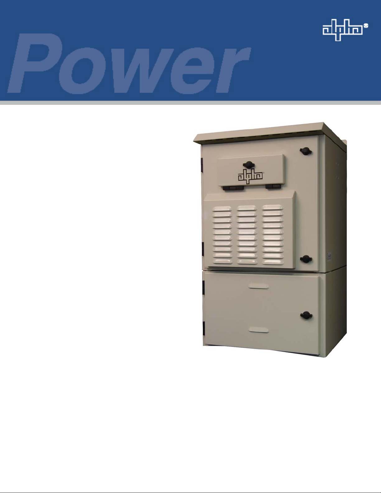
Fiber Backhaul Enclosure
Fiber Backhaul Enclosure (FBE)
Installation Manual
Effective: July 2009
Alpha Technologies
Page 2

Alpha Technologies
Power
®
Page 3

Fiber Backhaul Enclosure
Installation Manual
021-081-B0-001, Rev. A
Effective Date: July, 2009
Copyright© 2009
Alpha Technologies, Inc.
NOTE:
Alpha denies responsibility for any damage or injury involving its enclosures, power supplies, generators,
batteries or other hardware, manufactured by Alpha or members of the Alpha Group, when used for an
unintended purpose, installed or operated in an unapproved manner, or improperly maintained.
NOTE:
Photographs and drawings contained in this manual are only for illustrative purposes. These photographs and
drawings my not exactly match your installation.
NOTE:
Review the written and illustrative information contained in this manual before proceeding. If there are
questions regarding the safe installation or operation of this product, please contact Alpha Technologies or
your nearest Alpha representative.
Contacting Alpha Technologies: www.alpha.com
For general product information and customer service (7 AM to 5 PM, Pacifi c Time), call
021-081-B0-001 Rev.A
OR
1-800-863-3930
For complete technical support, call
1-800-863-3364
7 AM to 5 PM, Pacifi c Time or 24/7 emergency support
3
Page 4

Table of Contents
Safety Information ................................................................................................................. 5
1.0 Introduction .................................................................................................................8
1.1 Fiber Backhaul Enclosure ................................................................................8
1.2 Fiber Backhaul Enclosure (FBE) Specifi cations ............................................ 10
1.3 Parts List .........................................................................................................11
2.0 Installation.................................................................................................................12
2.1 Lifting ............................................................................................................. 12
2.2 Enclosure Installation, H-Bracket ................................................................... 15
2.3 Connecting Utility Power ................................................................................ 16
2.4 Enclosure Cooling .......................................................................................... 17
2.5 Cabinet Air Filtration.......................................................................................17
Figures & Tables
Fig. 1-1 Fiber Backhaul Enclosure ..................................................................................... 8
Fig. 1-2 Fiber Backhaul Enclosure (open) .......................................................................... 9
Fig. 2-1 Enclosure Lifting Arrangement ............................................................................ 12
Fig. 2-2 Enclosure Dimensions (Without Battery Cabinet) ............................................... 13
Fig. 2-3 Enclosure Dimensions (With Battery Cabinet) .................................................... 13
Fig. 2-4 Enclosure Dimensions cont'd .............................................................................. 14
Fig. 2-5 FBE Installation ................................................................................................... 15
Table 1-1 Specifi cations ......................................................................................................10
Table 1-2 Parts List ...............................................................................................................11
4
021-081-B0-001 Rev. A
Page 5
Safety Notes
Review the drawings and illustrations contained in this manual before proceeding. If there are any questions
regarding the safe installation or operation of the system, contact Alpha Technologies or the nearest Alpha
representative. Save this document for future reference.
To reduce the risk of injury or death, and to ensure the continued safe operation of this product, the following
symbols have been placed throughout this manual. Where these symbols appear, use extra care and
attention.
ATTENTION
The use of ATTENTION indicates specifi c regulatory/code requirements that may affect the placement of
equipment and /or installation procedures.
NOTE:
A NOTE provides additional information to help complete a specifi c task or procedure.
CAUTION!
The use of CAUTION indicates safety information intended to PREVENT DAMAGE to material or
equipment.
WARNING!
WARNING presents safety information to PREVENT INJURY OR DEATH to the technician
or user.
021-081-B0-001 Rev.A
5
Page 6

Battery Maintenance Guidelines
The battery maintenance instructions listed below are for reference only. Battery manufacturer’s instructions
for transportation, installation, storage or maintenance take precedence over these instructions.
• To prevent damage, inspect batteries every 3 months for:
Signs of battery cracking, leaking or swelling. The battery should be replaced immediately by
authorized personnel using a battery of the identical type and rating.
Signs of battery cable damage. Battery cable should be replaced immediately by Authorized Personnel
using replacement parts specifi ed by vendor.
Loose battery connection hardware. Refer to battery manufacturer’s documentation for the correct
torque and connection hardware for the application.
• Apply battery manufacturer’s specifi ed antioxidant compound on all exposed connections.
• Verify battery terminals and/or exposed connection hardware is not within 2 inches of a conductive
surface. Reposition batteries as necessary to maintain adequate clearance.
• Clean up any electrolyte (battery emission) in accordance with all federal, state, and local regulations or
codes.
• Proper venting of the enclosure is recommended. Follow the Battery Manufacturer’s approved
transportation and storage instructions.
• Always replace batteries with those of an identical type and rating. Never install old or untested batteries.
• Do not charge batteries in a sealed container. Each individual battery should have at least 0.5
inches of space between it and all surrounding surfaces to allow for convection cooling.
• All battery compartments must have adequate ventilation to prevent an accumulation of potentially
dangerous gas.
Recycling and Disposal Instructions
Spent or damaged batteries are considered environmentally unsafe. Always recycle used batteries or dispose
of the batteries in accordance with all federal, state and local regulations.
Electrical Safety
• Lethal voltages are present within the power supply and electrical boxes. Never assume that an electrical
connection or conductor is not energized. Check the circuit with a volt meter with respect to the grounded
portion of the enclosure (both AC and DC) prior to any installation or removal procedure.
• Always use the buddy system when working under hazardous conditions.
• A licensed electrician is required to install permanently wired equipment.
• Input voltages can range up to 240 Vac. Ensure that utility power is disabled before beginning installation
or removal.
• Ensure no liquids or wet clothes contact internal components.
• Hazardous electrically live parts inside this unit are energized from batteries even when the AC input
power is disconnected.
Mechanical Safety
• Keep hands and tools clear of fans. Fans are thermostatically controlled and will turn on automatically.
• Power supplies can reach extreme temperatures under load.
• Use caution around sheet metal components and sharp edges.
6
021-081-B0-001 Rev. A
Page 7

Battery Safety Notes
WARNING!
Lead-acid batteries contain dangerous voltages, currents and corrosive material. Battery
installation, maintenance, service and replacement must be performed only by authorized
personnel.
Chemical Hazards
Any gelled or liquid emissions from a valve-regulated lead-acid (VRLA) battery contain dilute sulfuric
acid, which is harmful to the skin and eyes. Emissions are electrolytic, and are electrically conductive and
corrosive.
To avoid injury:
• Servicing and connection of batteries shall be performed by, or under the direct supervision of, personnel
knowledgeable of batteries and the required safety precautions.
• Always wear eye protection, rubber gloves, and a protective vest when working near batteries. Remove
all metallic objects from hands and neck.
• Batteries produce explosive gases. Keep all open fl ames and sparks away from batteries.
• Use tools with insulated handles, do not rest any tools on top of batteries.
• Batteries contain or emit chemicals known to the State of California to cause cancer and birth defects
or other reproductive harm. Battery post terminals and related accessories contain lead and lead
compounds. Wash hands after handling (California Proposition 65).
• Wear protective clothing (insulated gloves, eye protection, etc.) whenever installing, maintaining,
servicing, or replacing batteries.
• If any battery emission contacts the skin, wash immediately and thoroughly with water. Follow your
company’s approved chemical exposure procedures.
• Neutralize any spilled battery emission with the special solution contained in an approved spill kit or with
a solution of one pound Bicarbonate of soda to one gallon of water. Report chemical spill using your
company’s spill reporting structure and seek medical attention if necessary.
• All battery compartments must have adequate ventilation to prevent an accumulation of potentially
dangerous gas.
• Prior to handling the batteries, touch a grounded metal object to dissipate any static charge that may have
developed on your body.
• Never use uninsulated tools or other conductive materials when installing, maintaining, servicing or
replacing batteries.
• Use special caution when connecting or adjusting battery cabling. An improperly connected battery cable
or an unconnected battery cable can make contact with an unintended surface that can result in arcing,
fi re, or possible explosion.
021-081-B0-001 Rev.A
7
Page 8

1.0 Introduction
1.1 Fiber Backhaul Enclosure
Alpha’s new Fiber Backhaul Enclosure is engineered to house optical fi ber equipment to support high
speed cellular data backhaul. Built with eleven rackmount spaces, the Alpha FBE is able to house
fi ber and powering gear including an Ethernet switch, power inverters, rectifi ers, fi ber splice tray, GMT
and additional controls. Optional confi gurations enable the addition of Batteries, DC rectifi ers and a
Service Utility Entrance. With Telecom-grade, padlockable quarter-turn locks and Demark access, the
FBE offers easy maintenance access and complete security.
NOTE:
For Fiber Backhaul Enclosure wiring diagrams and alarm information, see Fiber Backhaul Enclosure System
Schematics, Alpha P/N 021-081-08.
Figure 1-1, Fiber Backhaul Enclosure
8
021-081-B0-001 Rev. A
Page 9
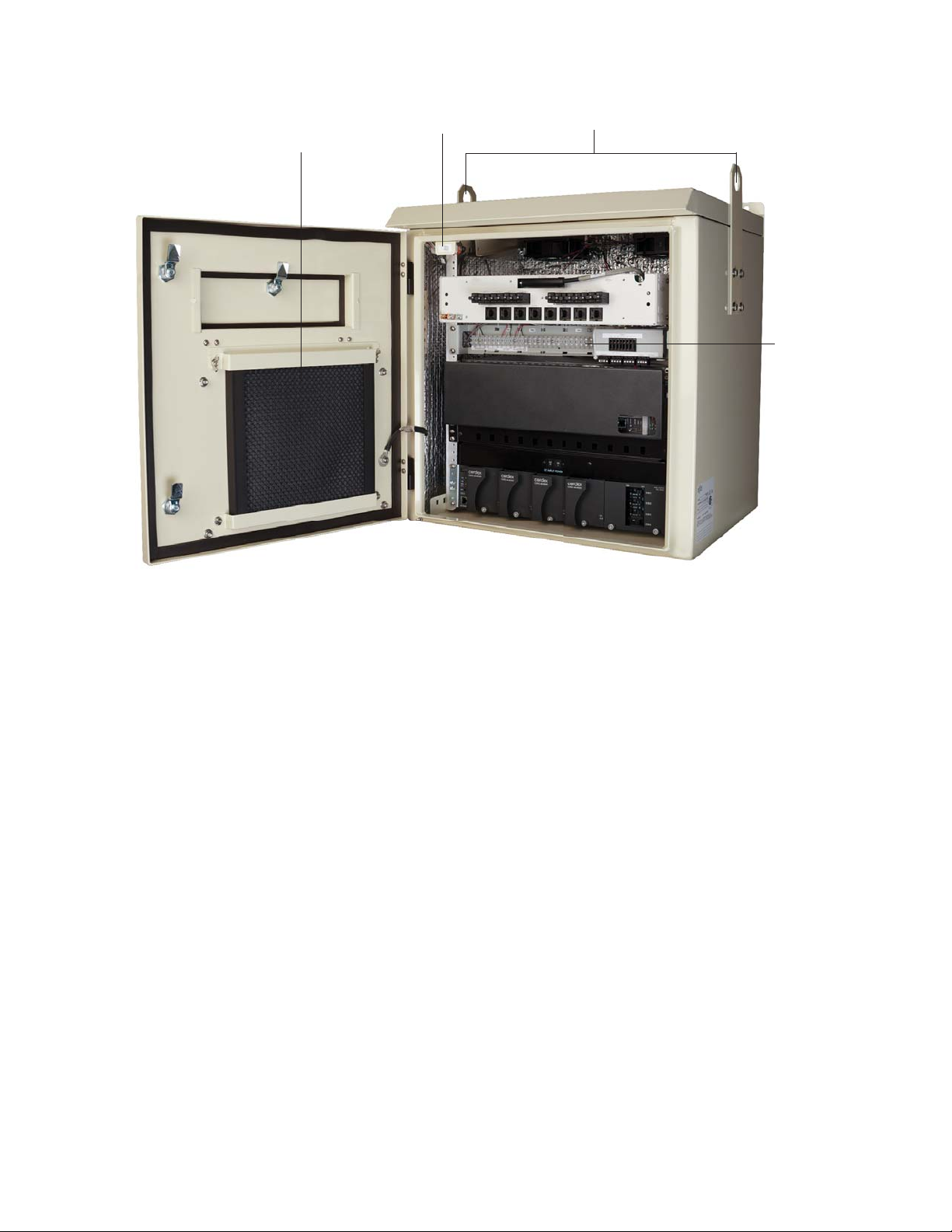
1.0 Introduction
Electrostatic Air Filter
Tamper Switch
Optional Enclosure Lifting Kit
Fuse panel
Figure 1-2, Fiber Backhaul Enclosure (open)
021-081-B0-001 Rev.A
9
Page 10

1.0 Introduction
1.2 Fiber Backhaul Enclosure (FBE) Specifi cations
Fiber Backhaul Enclosure
Material: Aluminum
Exterior Finish: Powdercoated exterior
Exterior hardware: Stainless Steel
Interior hardware: Stainless Steel and/or Zinc plated
Mechanical
Dimensions (maximum)
Width (in/mm): 23/584
Height (in/mm): 27/686
Depth (in/mm): 22.3/565
Weight (lbs/kg): 57/26
Enclosure External Mounting: Wall or H-bracket
Enclosure Internal Mounting: Adjustable (front to back) 19” equipment rack.
Door(s): Front: Hinged, with quarter-turn Telecom-grade locks
Knockouts: 2 x 2", 2 x 1.5", 4 x 0.75"
Environmental
Cooling: Redundant fans; 24 or 48Vdc, ball bearing, sealed, >70,000hr MTBF
Solar Insulation: 3/16" foil blanket (minimum)
Vent/Bug Screen: 20x20 mesh
Operating Temperature: -40° to 120°F/-40° to 49°C
Safety
Agency Standards: CSA CSA C22.2 No 60950-01-07; 60950-22-07
Optional Service Entrance: SUSE rated
Grounding: Permanent chassis ground for #6AWG wire
* "Information Technology Equipment Safety"
Fiber Backhaul Enclosure
11RU with maximum equipment depth of 15", up to 17" without optional din rail and ground bar
Demark/craft access - 2RU in height for eight RJ45 connectors with surge protection and two
LGX fi ber connector panels
UL UL 60950-1; UL 60950-22-2007
Cabinet NEMA Type 3R
Fiber Backhaul Enclosure
(
with Battery Cabinet)
23/584
41/1041
22.3/565
82/37.5
10
Table 1-1, FBE Specifi cations
021-081-B0-001 Rev. A
Page 11

1.3 Parts List
Enclosure Components
Description Part Number
Enclosure Assembly, FBE 031-296-20
Optional Components
Description Part Number
Temperature alarm switch 171-005-10
Din rail, accessory mounting 605-752-A1-001
Fan controller, 24Vdc 704-696-31
Enclosure Lifting Kit 744-941-25
Fan tray assembly, 24Vdc 746-062-21
Enclosure tamper switch kit 746-064-20
GMT style fuse panel, 24Vdc 746-065-20
Spare Components
Description Part Number
Tamper Switch 424-050-19
GMT Fuse, 10A 460-069-10
GMT Fuse, 5A 460-084-10
Replacement Fan (pair), 24Vdc 746-072-20
Electrostatic Air Filter 565-151-10
1.0 Introduction
Table 1-2, Parts List
021-081-B0-001 Rev.A
11
Page 12

2.0 Installation
2.1 Lifting
NOTE:
Remove the lifting ears after installation. The ears are made of steel and may rust over time.
WARNING!
Do not allow personnel to walk beneath the suspended unit during the lifting operation. Use
steel-toe work shoe protection. Use "hard hats" at all times during this procedure.
CAUTION!
Do not lift the enclosure with the equipment or batteries in place. Ensure load capacity of lifting
equipment is rated for the weight of the Fiber Backhaul Enclosure.
Attach the lifting chain to the eyebolts located in the top of the enclosure. Verify the adjustable chain
links are tightened securely. Also verify the length of the cable between the eyebolts and the lifting
hook (2d) is at least twice the distance (d) between the lifting eyebolts and the lifting angle of the
chain is greater than or equal to 60 degrees.
2
DX
D
Fig. 2-1, Enclosure Lifting Arrangement
12
021-081-B0-001 Rev. A
Page 13

2.2 Enclosure Installation, H-Bracket
23” (584mm)
21” (534mm)
13” (329mm)
22.2” (564mm)
20” (508mm)
1” (25mm)
2.0 Installation
0.5” (13mm)
O
24.4” (620mm)
22.1” (561mm)
4.8” (123mm)
26.9” (683mm)
Figure 2-2, Enclosure Dimensions (without battery cabinet)
40.9” (1038mm)
25.9” (657mm)
39.9” (1013mm)
021-081-B0-001 Rev.A
12.9” (328mm)
Figure 2-3, Enclosure Dimensions (with Battery Cabinet)
13
Page 14

1.0 Introduction
2.2 Enclosure Installation, H-Bracket (continued)
41.0” (1042mm)
Notes:
1) Standard FBE units are equipped with Left-hand
opening doors. Right-hand opening doors are
available as an option.
2) Maximum equipment depth for standard confi guration
is 15” (380mm). If optional DIN rail and ground bar are
not required, the EIA rails may be moved forward to
increase maximum depth to 17” (432mm).
25.0” (635mm)
18.313” (465 mm)
11U USABLE RACK UNITS
15" (380 mm)
MAX EQUIPMENT DEPTH
14
Figure 2-4, Enclosure Dimensions cont'd
021-081-B0-001 Rev. A
Page 15

2.2 Enclosure Installation, H-Bracket (continued)
Most codes require the base of the enclosure to be located a minimum height from the ground. Always
verify height restrictions before proceeding.
Recommended Tools and Materials:
• Ratchet with 5/8" (19mm) socket
• Level
• 7/16" x 1" (M12 x 25) hex head stainless steel bolts (quantity 4)
• 1” (25.4mm) diameter (minimum 0.1"/2.5mm thick) stainless steel fl at washer for 7/16” (M12) bolt
(quantity 4)
• Stainless steel helical lock washer for 7/16” (M12) bolt (quantity 4)
• Lifting kit (optional)
Installation Procedure:
1. Position the enclosure on an H-Bracket capable of supporting 350lbs (160kg).
2.0 Installation
2. The optional lifting ears may be used to raise and position the empty enclosure.
3. Using a level, ensure that the enclosure base is parallel to the ground.
4. Secure the enclosure to the H-Bracket using four user-supplied 7/16" x 1" (M12 x 25) hex head
stainless steel bolts, helical lock washers and fl at washers.
29.5”
(657mm)
39.9”
(1013mm)
Stainless Steel Hex Head Bolt,
Helical lock washer & Flat Washer
(4 Places)
021-081-B0-001 Rev.A
Figure 2-5, FBE Installation
15
Page 16

2.0 Installation
2.3 Connecting Utility Power
WARNING!
ONLY qualifi ed personal should connect the utility power. Power must be connected in
compliance with local electrical codes, and common safety practices must be observed.
ATTENTION:
• Connection to utility power may need to be approved by the local utility before installing the
enclosure.
• Your local authority may require that a service disconnect switch (UL listed) be provided by the
installer and be connected between the power source and the enclosure.
WARNING!
Low impedance grounding is mandatory for personnel safety and critical for the proper
operation of the cable system .
Strike (Lightning) Ground
Lightning strikes, grid switching, or other aberrations on the power line and/or communications cable have the
potential to cause high-energy transients which can damage the powering or communitations systems. Without a lowimpedance path to ground, the current, when traveling through wires of varying impedance, produce damaging high
voltage. The most viable method available to protect the system from damage is to divert these unwanted high-energy
transients along a low-impedance path to ground. A low-impedance path to ground prevents these currents from
reaching high voltage levels and posing a threat to equipment. The single-point grounding system provides a lowimpedance path to ground, and the key to its success is the proper bonding of the ground rods, so the components of
the grounding system appear as a single point of uniform impedance. Alpha recommends the use of a surge arresting
device electrically bonded to the grounding system.
NOTE:
All ground rod connections must be made by means of a listed grounding clamp suitable for direct burial or
exothermically welded.
16
021-081-B0-001 Rev. A
Page 17

2.0 Installation
2.4 Enclosure Cooling
NOTE:
Consultation with Alpha Applications Engineering is required. Provisions must be made for adequate air
fl ow in the cabinet, equipment total heat dissipation load inside the cabinet, equipment min/max operating
temperatures, equipment over-temp fail safe shutdown capability, environmental outdoor design conditions,
and battery back up run times.
• Cooling capacity 200W dissipated with 10ºC rise over ambient.
• Two 100 CFM fans with variable speed temperature control.
• Fans are off below 25ºC. Fans increase from 40% to 100% with increased enclosure temperature
from 25ºC to 45ºC. Power to the Fan Control PCBA must be provided by a circuit breaker or fuse. 5A
recommended; 10A maximum.
• Form C dry contact alarm, fan fail, open on alarm.
• Maximum power draw 23W.
2.5 Cabinet Air Filtration
The system has an electrostatic fi lter that should be inspected for cleaning or replacement every six
months depending on time of year or environment. Clean the fi lters by back fl ushing with water in the
direction indicated and reinstall the fi lter with air fl ow direction pointing into the enclosure and drain
holes at the bottom.
NOTE:
Some environments may require more frequent inspections to maintain optimum airfl ow.
021-081-B0-001 Rev.A
17
Page 18

2.0 Installation
18
021-081-B0-001 Rev. A
Page 19

Alpha Technologies
Power
®
Alpha Technologies
3767 Alpha Way
Bellingham, WA 98226
USA
Tel: +1(360) 647-2360
Fax: +1(360) 671-4936
Web: www.alpha.com
Alpha Technologies Ltd.
4084 McConnell Court
Burnaby, BC, V5A 3N7
CANADA
Tel: +1(604) 430-1476
Fax: +1(604) 430-8908
Alpha Technologies
Europe Ltd.
Twyford House
Thorley
Bishop's Stortford
Herfordshire
CM22 7PA
UNITED KINGDOM
Tel: +44 1279-501110
Fax: +44 1279-659870
Alpha Technologies GmbH
Hansastrasse 8
D-91126 Schwabach
GERMANY
Tel: +49-9122-79889-0
Fax: +49-9122-79889-21
Alphatec, Ltd
P.O. Box 56468
Limassol, Cyprus
CYPRUS
Tel: +357-25-375675
Fax: +357-25-359595
Alpha Technologies France
34, Grande Rue
Bétheny, F-51450
FRANCE
Phone: +33 32 64990 54
Fax: +33 95 60205 01
Copyright © 2009 Alpha Technologies, Inc. All rights reserved. Alpha is a registered trademark of Alpha Technologies. 021-081-B0-001 Rev. A
Due to continuing product improvements, Alpha reserves the right to change specifi cations without notice.
 Loading...