

Page 1
FBE2322 Enclosure System
Technical Manual
Effective: December, 2012
Page 2

Alpha Technologies
Power
®
2
031-314-B0-001, Rev. A (12/2012)
Page 3

FBE2322 Enclosure
Technical Manual
031-314-B0-001, Rev. A
Effective Date: December, 2012
Copyright© 2012
Alpha Technologies, Inc.
NOTE:
Alpha denies responsibility for any damage or injury involving its enclosures, power supplies, generators,
batteries or other hardware, manufactured by Alpha or members of the Alpha Group, when used for an
unintended purpose, installed or operated in an unapproved manner, or improperly maintained.
NOTE:
Photographs and drawings in this manual are for illustrative purposes only and might not exactly match your
installation.
NOTE:
Review this manual before proceeding. If there are questions regarding the safe installation or operation of
this product, please contact Alpha Technologies or your nearest Alpha representative.
For the most recent version of this Technical Manual or wiring
schematics visit www.alpha.com
Contacting Alpha Technologies: www.alpha.com
or
For general product information and customer service (7 AM to 5 PM, Pacic Time), call
1-800-863-3930
For complete technical support, call
1-800-863-3364
7 AM to 5 PM, Pacic Time or 24/7 emergency support
To report errors in this document, send email to:Techpubs@alpha.com
3031-314-B0-001, Rev. A (12/2012)
Page 4

Table of Contents
Safety Notes ............................................................................................................................................................... 6
Battery Maintenance Guidelines...................................................................................................................................... 7
Recycling and Disposal Instructions ................................................................................................................................ 7
Mechanical Safety ........................................................................................................................................................... 7
Battery Safety Notes........................................................................................................................................................ 8
Chemical Hazards ........................................................................................................................................................... 8
1.0 Introduction ............................................................................................................................................................... 9
1.1 FBE2322 Enclosure System Overview ............................................................................................................... 9
1.2 FBE2322Specications ................................................................................................................................... 10
1.3 FBE2322 Component Exterior Dimensions ...................................................................................................... 12
1.4 FBE2322 Enclosure System Shipping .............................................................................................................. 13
1.5 FBE2322 Parts Tables ...................................................................................................................................... 14
2.0 Installation ............................................................................................................................................................. 16
2.1 FBE2322 Enclosure Installation Overview ....................................................................................................... 16
2.2 Site Selection .................................................................................................................................................... 16
2.3 Enclosure Lifting (Optional) .............................................................................................................................. 17
2.4 Enclosure Installation, H-Frame/Wall Bracket Mounting .................................................................................. 17
2.5 Enclosure Installation, Pole Mounting .............................................................................................................. 19
2.5.1 Wooden Pole ........................................................................................................................................... 19
2.5.2 Concrete or Steel Pole ............................................................................................................................ 21
2.6 Ground-mount Installation ................................................................................................................................ 22
2.7 Enclosure Grounding ........................................................................................................................................ 26
2.8 Equipment Installation, FBE2322-ENC ............................................................................................................ 27
2.9 Equipment Installation, FBE2322-ENCBEE .................................................................................................... 28
2.10 Battery Installation .......................................................................................................................................... 30
3.0 Environmental Control Systems .............................................................................................................................. 32
3.1 FBE2322 Enclosure Environmental Control Overview ..................................................................................... 31
3.2 FBE2322 Fan Cooling ...................................................................................................................................... 31
3.3 FBE2322 AC Air Conditioner ........................................................................................................................... 32
3.4 FBE2322 Heat Exchanger ............................................................................................................................... 33
3.5 FBE2322 Emergency Fan ................................................................................................................................ 33
4.0 Maintenance ............................................................................................................................................................ 34
4.1 FBE2322 Enclosure Maintenance .................................................................................................................... 34
4.2 FBE2322 Environmental Control Maintenance ................................................................................................ 34
4.2.1 FBE2322 Air Filter Replacement ......................................................................................................... 34
4.2.2 FBE2322 Heat Exchanger ................................................................................................................... 34
4.2.3 FBE2322 AC Air Conditioner ............................................................................................................... 34
4
031-314-B0-001, Rev. A (12/2012)
Page 5

Figures and Tables
Fig. 1-1, FBE2322 Enclosure System Components ............................................................................................................... 9
Fig. 1-3, FBE2322-ENC Base Cabinet Exterior Dimensions ................................................................................................ 12
Fig. 1-4, FBE2322-AEE/BEE Auxiliary Equipment/Battery Expansion Enclosure Exterior Dimensions ...............................12
Fig. 1-5, FBE2322-P10 10” Pedestal Exterior Dimensions ..................................................................................................12
Fig. 1-2, FBE2322-AEE Example of Hardware Position for Shipping - Rear View ............................................................... 13
Fig. 1-6, FBE2322-P10 10” Pedestal Exterior Dimensions ..................................................................................................13
Fig. 1-7, FBE2322-ENC Footprint and Interior Cabinet Dimensions .................................................................................... 13
Fig. 2-1, Enclosure Lifting Arrangement ...............................................................................................................................17
Fig. 2-2, Enclosure Mounting Dimensions. ........................................................................................................................... 17
Fig. 2-3, Enclosure w/ Open Door Dimensions ....................................................................................................................17
Fig. 2-4, FBE2322-AEE H-Frame Mounting Example . ........................................................................................................ 18
Fig. 2-5, FBE2322-AEE H-Frame Mounting Hardware Detail . ............................................................................................18
Fig. 2-6, FBE2322 Series Wooden Pole Mounting ...............................................................................................................20
Fig. 2-7, FBE2322 Series Concrete or Steel Pole Mounting ................................................................................................21
Fig. 2-8, Ground-mount Positioning and Safety Example ....................................................................................................22
Fig. 2-9, FBE2322 Precast Polymer Pad Dimensions .......................................................................................................... 23
Fig. 2-10, Representative Site Arrangement ........................................................................................................................24
Fig. 2-11, Lightning Protection Ground Ring (Recommended Installation) .......................................................................... 26
Fig. 2-12, 3/8" 2-Hole, 1" Ct, Enclosure Ground Mount Location ......................................................................................... 26
Fig. 2-13, Pole Mount Lightning Protection (Recommended Installation) ...........................................................................26
Fig. 2-14, FBE2322-ENC Standard Equipment Conguration Example ..............................................................................27
Fig. 2-15, FBE2322-ENCBEE Stanrdard Equipment Conguration Example ...................................................................... 28
Fig. 2-16, Example of Battery Installation ............................................................................................................................. 29
Fig. 2-17, Example of Battery Stack Up ...............................................................................................................................30
Fig. 2-18, Inline Fuse Stack Up ............................................................................................................................................30
Fig. 2-19, Example of Completed Battery Installation ..........................................................................................................30
Fig. 3-1, ICEQube AC Air Conditioner Control Panel ...........................................................................................................33
Fig. 4-1, Removing Security Fasteners ................................................................................................................................35
Fig. 4-2, Rotating the Filter Bracket ......................................................................................................................................35
Fig. 4-3, Reinstalling the Filter Bracket.................................................................................................................................35
Fig. 4-4, Removing and Reinstalling the Filter .....................................................................................................................36
Table 1-1, FBE2322 Enclosure Specications...................................................................................................................... 10
Table 1-2, FBE2322 Battery Specications ..........................................................................................................................10
Table 1-3, FBE2322 Cooling Specications ......................................................................................................................... 11
Table 1-4, FBE2322 Parts Table ...........................................................................................................................................14
Table 2-1, FBE2322 Enclosure System Installation Options ................................................................................................16
Table 2-2, Enclosure Pole Mounting Dimension ...................................................................................................................19
Table 3-1, FBE2322 AC Air Conditioner Specications ........................................................................................................32
5031-314-B0-001, Rev. A (12/2012)
Page 6

Safety Notes
Review the drawings and illustrations contained in this manual before proceeding. If there are any questions regarding
the safe installation or operation of the system, contact Alpha Technologies or the nearest Alpha representative. Save this
document for future reference.
To reduce the risk of injury or death and to ensure the continued safe operation of this product, the following symbols have
been placed throughout this manual. Where these symbols appear, use extra care and attention.
ATTENTION:
The use of ATTENTION indicates specic regulatory/code requirements that may affect the placement of equipment and /
or installation procedures.
NOTE:
A NOTE provides additional information to help complete a specic task or procedure.
CAUTION!
The use of CAUTION indicates safety information intended to PREVENT DAMAGE to material or
equipment.
WARNING!
WARNING presents safety information to PREVENT INJURY OR DEATH to the technician or
user.
6
031-314-B0-001, Rev. A (12/2012)
Page 7

Battery Maintenance Guidelines
The battery maintenance instructions listed below are for reference only. Battery manufacturer’s instructions for
transportation, installation, storage or maintenance take precedence over these instructions.
• To prevent damage, inspect batteries every 3 months for:
Signs of battery cracking, leaking or swelling. The battery should be replaced immediately by authorized personnel
using a battery of the identical type and rating.
Signs of battery cable damage. Battery cable should be replaced immediately by Authorized Personnel using
replacement parts specied by vendor.
Loose battery connection hardware. Refer to battery manufacturer’s documentation for the correct torque and
connection hardware for the application.
• Apply battery manufacturer’s specied antioxidant compound on all exposed connections.
• Verify battery terminals and/or exposed connection hardware is not within 2 inches of a conductive surface. Reposition
batteries as necessary to maintain adequate clearance.
• Clean up any electrolyte (battery emission) in accordance with all federal, state, and local regulations or codes.
• Proper venting of the enclosure is recommended. Follow the Battery Manufacturer’s approved transportation and
storage instructions.
• Always replace batteries with those of an identical type and rating. Never install old or untested batteries.
• Do not charge batteries in a sealed container. Each individual battery should have at least 0.5 inches of space
between it and all surrounding surfaces to allow for convection cooling.
• All battery compartments must have adequate ventilation to prevent an accumulation of potentially dangerous gas.
Recycling and Disposal Instructions
Spent or damaged batteries are considered environmentally unsafe. Always recycle used batteries or dispose of the
batteries in accordance with all federal, state and local regulations.
Electrical Safety
• Lethal voltages are present within the power supply and electrical boxes. Never assume that an electrical connection
or conductor is not energized. Check the circuit with a volt meter with respect to the grounded portion of the enclosure
(both AC and DC) prior to any installation or removal procedure.
• Always use the buddy system when working under hazardous conditions.
• A licensed electrician is required to install permanently wired equipment.
• Input voltages can range up to 240Vac. Ensure that utility power is disabled before beginning installation or removal.
• Ensure no liquids or wet clothes contact internal components.
• Hazardous electrically live parts inside this unit are energized from batteries even when the AC input power is
disconnected.
Mechanical Safety
• Keep hands and tools clear of fans. Fans are thermostatically controlled and will turn on automatically.
• Power supplies can reach extreme temperatures under load.
• Use caution around sheet metal components and sharp edges.
7031-314-B0-001, Rev. A (12/2012)
Page 8

Battery Safety Notes
WARNING!
Lead-acid batteries contain dangerous voltages, currents and corrosive material. Battery
installation, maintenance, service and replacement must be performed only by authorized
personnel.
Chemical Hazards
Any gelled or liquid emissions from a valve-regulated lead-acid (VRLA) battery contain dilute sulfuric acid, which is harmful
to the skin and eyes. Emissions are electrolytic, and are electrically conductive and corrosive.
To avoid injury:
• Servicing and connection of batteries shall be performed by, or under the direct supervision of, personnel
knowledgeable of batteries and the required safety precautions.
• Always wear eye protection, rubber gloves, and a protective vest when working near batteries. Remove all metallic
objects from hands and neck.
• Batteries produce explosive gases. Keep all open ames and sparks away from batteries.
• Use tools with insulated handles, do not rest any tools on top of batteries.
• Batteries contain or emit chemicals known to the State of California to cause cancer and birth defects or other
reproductive harm. Battery post terminals and related accessories contain lead and lead compounds. Wash hands
after handling (California Proposition 65).
• Wear protective clothing (insulated gloves, eye protection, etc.) whenever installing, maintaining, servicing, or
replacing batteries.
• If any battery emission contacts the skin, wash immediately and thoroughly with water. Follow your company’s
approved chemical exposure procedures.
• Neutralize any spilled battery emission with the special solution contained in an approved spill kit or with a solution
of one pound Bicarbonate of soda to one gallon of water. Report chemical spill using your company’s spill reporting
structure and seek medical attention if necessary.
• All battery compartments must have adequate ventilation to prevent an accumulation of potentially dangerous gas.
• Prior to handling the batteries, touch a grounded metal object to dissipate any static charge that may have developed
on your body.
• Never use uninsulated tools or other conductive materials when installing, maintaining, servicing or replacing batteries.
• Use special caution when connecting or adjusting battery cabling. An improperly connected battery cable or an
unconnected battery cable can make contact with an unintended surface that can result in arcing, re, or possible
explosion.
8
031-314-B0-001, Rev. A (12/2012)
Page 9
1.0 Introduction
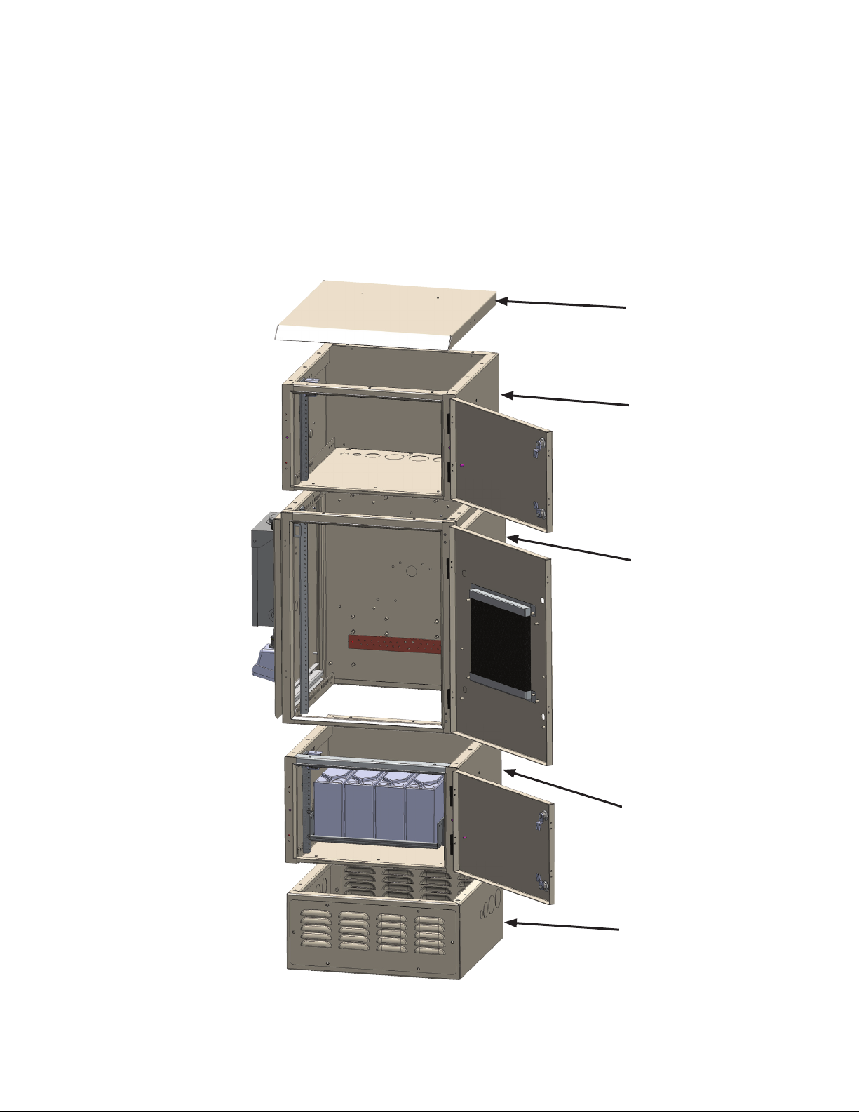
1.1 FBE2322 Enclosure System Overview
The FBE2322 is engineered to provide modular solutions for customer backhaul enclosure demands. The
various congurations offer wall, H-frame, pole, or ground mount options. Thermal management features
include convection cooling, fan, heat exchanger, or air conditioning, as well as an optional emergency
ventilation system for certain congurations. The FBE2322 delivers secure accessibility with expansion
capability even in multiple carrier scenarios.
FBE2322-LID
FBE2322-AEE
FBE2322-ENC
FBE2322-BEE
FBE2322-P10
Fig. 1-1, FBE2322 Enclosure System Components
9031-314-B0-001, Rev. A (12/2012)
Page 10
1.0 Introduction, continued
1.2 FBE2322Specications
FBE2322 Material
Material
Exterior Finish Powdercoated
Exterior hardware Stainless Steel
Interior hardware Stainless Steel and/or Zinc plated
Mechanical
Enclosure External Mounting Options Ground, Pole or H-Frame/Wall Bracket
FBE2322-ENC Enclosure Internal Mounting:
Door(s): Front Left or Right hinged, with quarter-turn Telecom-grade locks.
Access Panels: Left and Right with quarter-turn Telecom-grade locks.
Knockouts: Baseplate (optional): 2 x 2", 2 x 1.5", 4 x 0.75"
FBE2322-AEE Enclosure Internal Mounting: Adjustable (front to back) 19” equipment rack w/ 7RU.
Door(s): Front Left or Right Hinged, with quar ter-turn Telecom-grade lock.
Knockouts: Left and Right side: 2 x 2 ", 1 x 1.5", 1 x 0.75", Baseplate (optional): 2 x 2", 2 x 1.5", 4 x 0.75"
FBE2322-BEE Enclosure Internal Space: 20.2" W x 19.85" D x 12.25" H battery storage
Door(s): Front Left or Right Hinged, with quar ter-turn Telecom-grade lock
Knockouts: Left and Right side: 2 x 2 ", 1 x 1.5", 1 x 0.75", Baseplate: 2 x 2", 2 x 1.5", 4 x 0.75"
FBE2322- P10 Access Panels: Vented Front and Back
Knockouts: Left and Right side: 2 x 2 ", 1 x 1.5", 1 x 0.75"
Safety
Agency Standards
.10 0" Aluminum
Adjustable (front to back) 19" equipment rack w/ 15RU.
CAN/US UL/CSA 60950-01-07; UL/CSA 60950-22-07
Cabinet NEMA Type 3R
Table 1-1, FBE2322 Enclosure Specications
FBE2322 Battery Specications
70HPL-FT 115HPL-FT 220HPL-FT SBS B14F
Weight (lb/kg) 27.9/15.3 46.2/22.2 78.5/36 42 /19.1
Height (in/mm) 8.21/209 10.3/263 11.3/287 10.4/ 264
Width (in/mm)* 3.81/97 4.2 /108 4.24/108 3.8/97
Depth (in/mm)
Terminals
Torque (in-lbs/Nm)
Operating Temperature
Range Discharge °C (°F)
Heat Resistant High High High
Capacity 42Ah at 20hrs (to 1.75VPC)
Charge (with temp
compensation)(°F)
Float Charging Voltage @
25°C/77°F (VDC)
(*) – Dimensions at battery base.
* 9.84/250 11.3/287 15.59/396 11.9/303
M8 x 1.25-14mm M8 x 1.25 -14mm M8 x 1.25-14mm
71/8 71/8 71/8
-40°C to 60°C (-40°F to
140°F)
@ 25°C/77°F
-40°C to 60°C (-40°F to
140°F)
13.5 to 13. 6 13. 5 to 13 .6 13.5 to 13.6
-40°C to 60°C (-40°F to
140°F)
62Ah at 20hrs (to 1.75VPC)
@ 25°C/77°F
-40°C to 60°C (-40°F to
140°F)
-40°C to 60°C (-40°F to
140°F)
107Ah at 20hrs (to 1.75VPC)
@ 25°C/77°F
-40°C to 60°C (-40°F to
140°F)
M6 M
44/5
62Ah at 10hrs (to 1.80VPC)
@ 20°C/68°F
Table 1-2, FBE2322 Battery Specications
10
031-314-B0-001, Rev. A (12/2012)
Page 11

1.0 Introduction, continued
1.2 FBE2322Specications
FBE2322 Cooling Specications
Fan Cooling
General Description Two, variable speed, temperature controlled fans.
Airow Capacit y (per Fan) 118 CF M
Input Power ( Volts/Watts) 24 or 48Vdc/20 Watts for 2 Fans
Control Features Dual Fan PCBA w/ Red and Green LED Display
Operation Range (Temp°C/%Speed) 25– 45°C/5 0–10 0%
Alarms Form C dry contact alarm
AC Air Conditioner
Capacity Cooling IQ1000V – 1,000 BTUH @ 55º C (131ºF) ambient
Maximum Operating Temperature 55ºC (131º F)
Electrical IQ1000V – 3.1A @ 120VAC/60HZ maximum
High Enclosure Temperature Alarm* 45 º C (11 3º F)
Low Enclosure Temperature Alarm* 0º C (32º F)
Audible Alarm Default Setting* OFF
Digital Display Default Setting* ºC
Filter Maintenance Alarm Setting* Disabled
High Condenser Temperature Alarm* 76.7 ºC (170º F)
Heat Exchanger
Specication 040-025-12-001 040-025-13-001
Nominal Voltage (Vdc) 24 48
FLA (Full Load Amps) 3.5 1.75
Cooling Capacity 30.6W/°C (17W/°F) Cooling @ 65°C (149°F) Ambient Temperature
Operating Temperature Range -40°C –70°C
Maximum Temperature 65°C
Internal Fan Operating Range Off below 5°C; Minimum Speed @ 10°C; Variable to Max. Speed @ 20°C~30°C
Internal Fan Operating Range Off below 15°C; Minimum Speed @ 20°C; Variable to Max. Speed @ 30°C~45°C
High Temperature Alarm 70°C
Low Temperature Alarm -50°C
(*) – Alpha default settings may differ from ICEQube default settings.
Condenser High Temp. (76.7ºC/170ºF)
Filter Maintenance
IQ240 0VXS – 2400 BTUH @ 55ºC (131ºF) ambient
Heating 400W
IQ240 0VXS – 7.5A @ 120VAC/60HZ ma ximum
Table 1-3, FBE2322 Cooling Specications
11031-314-B0-001, Rev. A (12/2012)
Page 12
1.0 Introduction, continued
21.0
" (533mm)
23.0
" (584mm)
25.1
" (636mm)
32.0
" (812mm)
30.0
" (762mm)
27.3
" (693mm)
25.0
" (634mm)
18.5
" (470mm)
31.0
" (787mm)
.5
" (13mm)
1.0
" (25mm)
TYP
(Front View) (Right Side View) (Rear View)
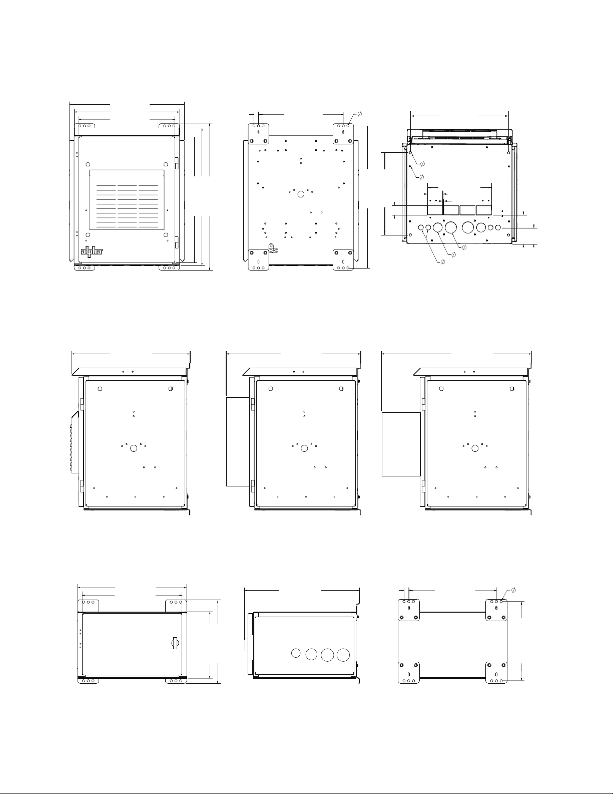
1.3 FBE2322 Component Exterior Dimensions
25.1
" (636mm)
23.0
" (584mm)
21.0
" (533mm)
(Front View) (Rear View) (Bottom View)
Fig. 1-2, FBE2322-ENC Base Cabinet Exterior Dimensions
" (812mm)
" (762mm)
" (693mm)
32.0
30.0
27.3
1.0
" (25mm)
TYP
18.5
" (470mm)
.5
" (13mm)
" (787mm)
31.0
" (50.8mm)
" (457mm)
2.0
18.0
.96
.28
21.5
" (24mm)
" (7mm)
14.0
1.0
" (546mm)
" (354.8mm)
3.31
" (84mm)
.25
" (7mm)
2.5
2.0
" (50.8mm)
" (25.4mm)
" (63.5mm)
" (161mm)
6.3
" (88.9mm)
3.5
25.0
" (634mm)
Fan & Filter
(Right Side View)
23.0
" (584mm)
21.0
" (533mm)
28.3
" (718mm)
Heat Exchanger
(Right Side View)
Fig. 1-3, FBE2322-ENC Environmental Control Options Side Dimensions
18.5
25.0
" (634mm)
" (25mm)
TYP
" (470mm)
30.8
" (783mm)
Air Conditioner
(Right Side View)
.5" (13mm)1.0
18.0" (457mm)
14.0" (356mm)
(Front View) (Right Side View) (Rear View)
Fig. 1-4, FBE2322-AEE/BEE Auxiliary Equipment/Battery Expansion Enclosure Exterior Dimensions
12
17.0" (431.8mm)
031-314-B0-001, Rev. A (12/2012)
Page 13

1.0 Introduction, continued
23.0
" (584mm)
10.0" (254mm)
23.0
" (584mm)
10.0" (254mm)
22.0
" (559mm)
21.0
" (533mm)
23.0
" (584mm)
18.0" (457mm)
14.0" (356mm)
25.0
" (634mm)
18.5
" (470mm)
17.0" (431.8mm)
.5" (13mm)1.0
" (25mm)
TYP
21.0
" (533mm)
23.0
" (584mm)
25.1
" (636mm)
32.0
" (812mm)
30.0
" (762mm)
27.3
" (693mm)
25.0
" (634mm)
18.5
" (470mm)
31.0
" (787mm)
.5
" (13mm)
1.0
" (25mm)
TYP
(Front View) (Right Side View) (Rear View)
(Front View) (Right Side View) (Rear View)
(Front View) (Right Side View) (Rear View)
21.0
" (533mm)
23.0
" (584mm)
18.0" (457mm)
14.0" (356mm)
25.0
" (634mm)
18.5
" (470mm)
17.0" (431.8mm)
.5" (13mm)1.0
" (25mm)
TYP
21.0
" (533mm)
23.0
" (584mm)
25.1
" (636mm)
32.0
" (812mm)
30.0
" (762mm)
27.3
" (693mm)
25.0
" (634mm)
18.5
" (470mm)
31.0
" (787mm)
.5
" (13mm)
1.0
" (25mm)
TYP
(Front View) (Right Side View) (Rear View)
(Front View) (Right Side View) (Rear View)
1.3 FBE2322 Component Exterior Dimensions, continued
23.0
" (584mm)
22.0
" (559mm)
23.0
" (584mm)
10.0" (254mm)
(Front View) (Right Side View) (Rear View)
21.5
" (546mm)
12.0
" (304mm)
.28
" (7mm)
.96
" (24mm)
(Bottom View)
Fig. 1-5, FBE2322-P10 10" Pedestal Exterior Dimensions
" (457mm)
" (304mm)
18.0
12.0
19.8
" (502mm)
17.5
" (445mm)
(Front View) (Right Side View)
Fig. 1-6, FBE2322-ENC Footprint and Interior Cabinet Dimensions
" (693mm)
27.3
25.0
" (634mm)
19.0
" (482mm)
10.0" (254mm)
1.4 FBE2322 Enclosure System Shipping
Each enclosure system may ship differently because of its modular design. Ensure that all components
are received and in proper order. Certain hardware (i.e. mounting brackets, lifting ears, etc.) may be
reoriented to facilitate packing and shipping demands (see Figure 1-7).
Brackets shipped
turned in
Fig. 1-7, FBE2322-AEE Example of Hardware Position for Shipping - Rear View
Brackets
reoriented for
mounting
13031-314-B0-001, Rev. A (12/2012)
Page 14

1.0 Introduction, continued
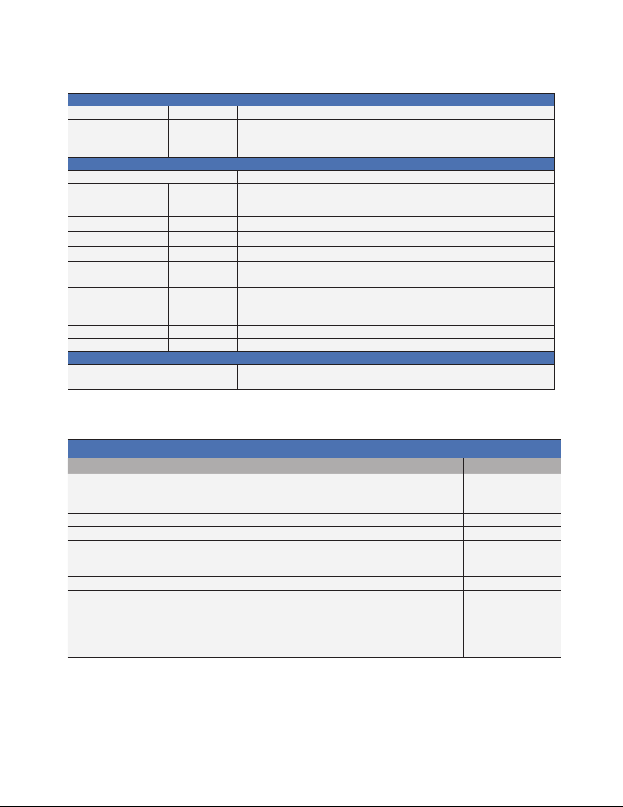
1.5 FBE2322 Parts Tables
Table 1-4 provides parts information for the FBE2322 Enclosure System. This material is for reference only. All
congurations must be approved by Alpha Engineering.
FBE Cabinet Parts
Part Name Part Number
FBE2322 Base Cabinet 031-314-20
Enclosure Base Plate 606-188-F2-001
Enclosure Base Plate w/ Emergency Exhaust Ports 746-181-20
Enclosure Lid 746-183-20
Enclosure Side Door 746-179-20
Enclosure Door Latch 1/4 Turn Knob 746-095-20
Enclosure Door Latch 1/4 Turn Knob Hex w/CP 746-095-21
Hex w/CP Door Latch Key 745-306-21
FBE Mounting Options
Part Name Part Number
FBE Mounting Kit 10" Pedestal 746 -194-20
FBE Mounting Kit Pole Mount 746-205-20
FBE Mounting Kit Wall Mount/H-Frame 746-206-20
FBE Pole Mount Bracket Concrete 591-557-20
FBE Pole Mount Bracket Wood 744-670-20
FBE Power/Equipment Options
Part Name Part Number
100A AC Service Load Center 745-266-23
70A BBX w/o CB 746-162-20
AC Gen Inlet Assembly 30A 745-264-20
120V/15A. GFCI Kit 746-213-20
Air Conditioner 120Vac/15A Receptacle Kit 746-214-20
Auxiliary 120Vac/20A Receptacle Kit 746-215-20
Surge Protector Kit lSA 120/240 745-946-20
Tamper Switch Kit 3 Door 746-064-22
Lifting Ears Kit FBE2322 746-204-20
FBE Ground Bars
Part Name Part Number
12 Position, 1/4" 2-Hole, 5/8" Ct, Isolated Buss Bar 745-235-24
12 Position, 1/4" 2-Hole, 5/8" Ct, Grounded Buss Bar 745-235-25
4 Position, 1/4" 2-Hole, 5/8" Ct, Ground Bar 746-093-21
15 Position, (14)1/4" 2-Hole, 5/8" Ct; (1)3/8" 2-Hole, 1" Ct, Ground Bar 746-188-20
14
Table 1-4, FBE2322 Parts Table
031-314-B0-001, Rev. A (12/2012)
Page 15

1.0 Introduction, continued
1.5 FBE2322 Parts Tables, continued
FBE Enclosure Cooling
Part Name Part Number
Ice Qube IQI000V 120Vac 60Hz Alarm 040-020-10-001
Ice Qube IQ2400VXS 120Vac 60Hz Alarm 040-021-10-001
48Vdc Fan Panel 746- 184-20
24Vdc Fan Panel 746-184-21
120Vac Fan Panel 746-184-22
24Vdc Heat Exchanger 040-025-12-001
48Vdc Heat Exchanger 040-025-13-001
Insulation Kit 1" (For Air Conditioner Congurations) 746-201-20
48Vdc Fan Control Board 746-098-20
24Vdc Fan Control Board 746 -098-21
48Vdc Overtemp Exhaustl Kit 746-224-20
24Vdc Overtemp Exhaust Kit 746-224-21
Cordex Assembly Parts
Part Name Part Number
Cordex Assembly 030-834-20-A002
Cordex Power Module 48-1.2kW 010-619-20-A001
Cordex Plug-in Breakers w/
Auxiliary Switch
1 Amp 470-300-10-A000 40 Amp 470-309-10-A000
3 Amp 470-301-10-A000 45 Amp 470-310-10-A000
5 Amp 470-302-10-A000 50 Amp 470-311-10-A000
10 Amp 470-303-10-A000 60 Amp 470-312-10-A000
15 Amp 470-304-10-A000 70 Amp 470-313-10-A000
20 Amp 470-305-10-A000 80 Amp 470-314-10-A000
25 Amp 470-306-10-A000 90 Amp 470-315-10-A000
30 Amp 470-307-10-A000 100 Amp 470-316-10-A000
35 Amp 470-308-10-A000
FBE GMT Fuse Options
Part Name Part Number Part Name Part Number
GMT Fuse 1/2 AMP 460-004-10 GMT Fuse 4 AMP 460-085-10
GMT Fuse 1 AMP 460-006-10 GMT Fuse 5 AMP 460-084-10
GMT Fuse 1-1/3 AMP 460-081-10 GMT Fuse 7-1/2 AMP 460-105-10
GMT Fuse 2 AMP 460-083-10 GMT Fuse 10 AMP 460-069-10
GMT Fuse 3 AMP 460-013-10 GMT Fuse 15 AMP 460-150-10
FBE Battery Accessories
Part Name Part Number
Battery Cable Kit #6AWG/100A Fuse 746-164-20
Battery Tray 19", Rack Mount Kit 746-200-20
Fuse, 100A 460-191-10
Part Number Cordex Plug-in Breakers w/
Part Number
Auxiliary Switch
Table 1-4, FBE2322 Parts Table, continued
15031-314-B0-001, Rev. A (12/2012)
Page 16

2.0 Installation
2.1 FBE2322 Enclosure Installation Overview
Installation requirements may differ for each conguration or customer specic application. The following
instructions provide guidelines for the most common enclosure conguration installations. Always follow
local codes and ordinances when designing and implementing your backhaul enclosure plans. Table 2-1
provides installation options for standard congurations. Consult your sales representative for installation
information if your conguration does not appear below.
FBE-AEE x x
FBE-ENC x x
FBE-ENC w/ Batteries x x
FBE ENC-BEE x x
FBE-AEE-ENC-BEE-P10 x* x
FBE-ENC-BEE-BEE-P10 x* x
FBE-AEE-AEE-ENC-P10 x* x
(*) - Installed without P10 plinth base.
FBE2322 Enclosure System Installation Options
Standard Congurations H-Frame Mount Pole Mount Ground Mount
Table 2-1, FBE2322 Enclosure System Installation Options
NOTE:
For ground mount congurations, do NOT exceed a maximum height of 72" (1.8m).
2.2 Site Selection
• Where possible, select a site above the 100-year ood plain and away from houses.
• Place in a shaded location to minimize the effects of solar loading.
• Locate in an area where airow can be maximized.
• Avoid locating the enclosure where it is an obstruction and would inhibit visibility.
• Locate the enclosure away from sprinkler systems or other sources of forced water.
• Locate the enclosure out of the prevailing wind to minimize the buildup of snow or the
accumulation of wind-borne dust.
• Ensure soil conditions are suitable for the the appropriate grounding system installation.
• Ensure cabling has been run and terminated at the site.
• Decide whether the enclosure will be placed on a precast concrete pad or on a pad poured on site.
• Contact a cable locating service, the local utility, and adjacent building supervisors to ensure
installation location and cable routing does not interfere with existing utility connections.
ATTENTION:
Ensure that all enclosure installations are installed per local, state, and federal codes and regulations. Local,
state, and federal codes and regulations supersede information provided in this manual.
16
031-314-B0-001, Rev. A (12/2012)
Page 17

2.0 Installation, continued
2.3 Enclosure Lifting (Optional)
WARNING!
Follow all rules and guidelines for safe lifting operation.
Secure the lifting straps/cable to the lifting ears. The length of the
cable/strap between the lifting ears and the hook (A) is at least
twice the distance (B) between the lifting ears (see Fig. 2-1).
A
NOTE:
B
Remove the lifting ears after installation. The ears are
made of steel and may rust over time.
Fig. 2-1, Enclosure Lifting
Arrangement
2.4 Enclosure Installation, H-Frame/Wall Bracket Mounting
H-Frame mounting brackets ship attached to your enclosure. They may be mounted in reverse for
convenience during shipping.
CAUTION!
• Never transport the unit with installed batteries. Doing so can cause injury or damage to the
enclosure and installed equipment. Install the batteries after you transport the unit to the site
and secure it to the H-frame.
• Alpha recommends that you position the enclosure on the H-frame in an area that restricts
unauthorized access.
• System installation at >5º angle from pole-axis is not recommended.
The size of the H-Frame and physical space needed for your enclosure will be determined by its
conguration. For FBE2322-ENC mounting dimensions, see Fig. 2-2. For other enclosure dimensions,
see Section 1.3. Place the enclosure to provide sufcient space for maintenance access (see Fig. 2-3).
18.5
1.0
" (25mm)
TYP
" (470mm)
.5
" (13mm)
" (787mm)
31.0
Fig. 2-2, Enclosure Mounting Dimensions
41.0” (1042mm)
25.0” (635mm)
Fig. 2-3, Enclosure w/ Open Door Dimensions
17031-314-B0-001, Rev. A (12/2012)
Page 18

2.0 Installation, continued
2.4 Enclosure Installation, H-Frame Mounting continued
Most codes require the base of the enclosure to be located a minimum height from the ground. Always
verify mounting height requirements before proceeding.
Recommended Customer Supplied Tools and Materials:
• Ratchet with 5/8” (19mm) socket
• Level
• Four 7/16-14 x 1" (M12 x 25mm) hex head stainless steel bolts
• Eight 7/16" stainless steel at washers
• Four 7/16"-14 (M12) lock washers
• Four 7/16"-14 (M12) hex nuts
• Structural slotted channel with mounting hardware
Procedure:
1. The FBE2322 Enclosures may ship with mounting brackets turned inward for convenience during
shipping. Remove the bracket mounting hardware and remount the brackets turned outward (see
Section 1.4).
2. Position the enclosure on an H-frame of structural slotted channels 17" apart (for FBE2322-AEE) on
center (see Fig. 2-4).
3. Loosely attach the enclosure to the structural slotted channel using (4) 7/16"-14 x 1" (M12 x 25) hex
head stainless steel bolts, (8) 7/16" (M12) lock washers, (4) 7/16" stainless steel at washers, and (4)
7/16"-14 (M12) hex nuts (see Fig. 2-5).
4. Using a level, ensure that the enclosure is parallel to the ground, and nal tighten all mounting
hardware.
5. The enclosure is now ready for grounding (see Page 26) and equipment installation.
18
Fig. 2-4, FBE2322-AEE H-Frame Mounting Example.
NOTE:
The optional lifting ears may be used to raise and position the empty enclosure. Lifting ears may ship
reversed.
Fig. 2-5, FBE2322-AEE H-Frame Mounting
Hardware Detail.
031-314-B0-001, Rev. A (12/2012)
Page 19

2.0 Installation, continued
2.5 Enclosure Installation, Pole Mounting
CAUTION!
• Never transport the unit with installed batteries. Doing so can cause injury or damage to the
enclosure and installed equipment. Install the batteries after you transport the unit to the site
and secure it to the pole.
• Alpha recommends that you position the enclosure on the opposite side of the pole from trafc.
This reduces the danger of falling equipment in the event that a pole is struck by an automobile.
• Mounting bolts must completely penetrate the wooden pole. Secure the bolts from the back with
a large washer and nut.
• Enclosure installation at >5º angle from pole-axis is not recommended.
• Different congurations may require more or less pole mounting bolts/strapping than indicated
in the instructions below. Always use the same number mounting hardware assemblies as the
total enclosure mounting brackets for any conguration.
ATTENTION:
The majority of poles belong to the local utility. Before installing an enclosure, have both the location and mounting
method approved by the utility. Because most codes require the enclosure to be located at a minimum height from
the ground, always verify local height restrictions before proceeding.
2.5.1 Wooden Pole
Tools and Materials Required (customer supplied):
• Two 5/8" (16mm) diameter machine bolts, length to suit pole
• Four 5/8" (16mm) split lock (helical spring) washers, zinc plated or better
• Two 5/8" (16mm) threaded hex nuts (UNC thread)
• Auger or drill for boring 11/16" (17.5mm) diameter holes in the wooden pole
• Mallet or hammer
• Assorted sockets
• Tape measure
• Three-foot level
Procedure:
1. Unpack the enclosure and galvanized brackets.
2. Mark the position for the upper bracket on the utility pole. Using a three-foot level to verify
the drill is level, drill a 11/16" (17.5mm) hole completely through the pole from the installation
side.
Enclosure Pole Mount Bracket Distances
Enclosure Distance (on center) (in/mm)
FBE2322-ENC 18/457.2
FBE2322-AEE 8/203.2
FBE2322-BEE 8/203.2
Table 2-2, Enclosure Pole Mounting Dimensions
3. Mark the location of the hole for the lower bracket the appropriate distance below the upper
bracket hole (see Table 2-2 for distances).
4. Using the three-foot level to verify drill angle, drill the 11/16" (17.5mm) hole or holes for the
lower bracket from the installation side of the pole.
NOTE:
Drill all holes from the enclosure side of the pole to ensure proper spacing.
19031-314-B0-001, Rev. A (12/2012)
Page 20

2.0 Installation, continued
2.5 Enclosure Installation, Pole Mounting, continued
2.5.1 Wooden Pole, continued
5. Secure the brackets to the pole using the 5/8" (16mm) machine bolts, washers, and nuts.
6. Lift the enclosure onto the brackets. It might be necessary to rock and pull the enclosure to
properly seat it on the brackets.
7. Secure the enclosure to the brackets using the 3/8"x 3/4" hex bolts.
8. Make sure all nuts and bolts are fully tightened and the anges of the brackets seat in the
wood.
9. The enclosure is now ready for grounding (see Page 26) and equipment installation.
Nut & Washer
5/8" (16mm) Bolts
Pole Mount Brackets
p/n 744-670-20
Enclosure Pole Mount Straps
p/n 746-205-20
18" (457.2mm)
Nut & Washer
Enclosure Ground
Cable
Fig. 2-6, FBE2322 Series Wooden Pole Mounting
20
031-314-B0-001, Rev. A (12/2012)
Page 21

2.0 Installation, continued
Cable
2.5 Enclosure Installation, Pole Mounting, continued
2.5.2 Concrete or Steel Pole
Tools and Materials Required (customer supplied):
• Stainless steel banding (or equivalent), rated to support loaded enclosure and sized for pole
diameter
• Assorted sockets
Procedure:
1. Unpack the enclosure and galvanized brackets; turn the enclosure facedown on a soft
surface.
2. Slide a bracket up through the enclosure’s lower mounting bracket. The bracket’s anges
must face away from the enclosure. Secure the lower mounting bracket using the 3/8" x 3/4"
hex bolt included.
3. Position the upper mounting bracket on the pole and secure using banding.
4. Lift the enclosure onto the upper mounting bracket and pull downward to properly seat it.
Center the enclosure on the pole.
5. Secure the lower mounting bracket on the pole using banding. Spacing between banding is
18"/457mm.
6. The enclosure is now ready for grounding (see Page 26) and equipment installation.
Pole Strap
18" (457.2mm)
Pole Mount Brackets
p/n 591-557-20
Pole Strap
Enclosure Pole Mount Straps
Enclosure Ground
Fig. 2-7, FBE2322 Series Concrete or Steel Pole Mounting
p/n 746-205-20
21031-314-B0-001, Rev. A (12/2012)
Page 22

2.0 Installation, continued
2.6
Ground-mount Installation
CAUTION!
Never transport the unit with installed batteries. Doing so can cause injury to the installer or damage
the enclosure and equipment. Install the batteries after you transport the unit to the site and secure
it to the pad.
ATTENTION:
It is the responsibility of the installer to meet the requirements of all applicable national and local codes. Alpha
Technologies assumes no responsibility or liability for failure of the installer to comply with the requirements of
all applicable local and national codes.
ATTENTION:
The appropriate grounding method for a particular location depends on soil type, available space, local codes,
NEC (National Electric Code), and other site-specic characteristics.
Alpha Technologies, Inc. cannot anticipate all the ways a vehicle could threaten an installed system or the
specic type of protection that is appropriate for a particular location. The following installation drawing for
Alpha’s Standby Power systems are general recommendations and not intended to be a specic guideline
for protecting the equipment. The numbers of bollard posts (or other protection devices) depend upon
equipment locations.
SIDEWALK
10’ (3m)
SPRINKLER HEAD
PAD
POSTS
Fig. 2-8, Ground-mount Positioning and Safety Example
22
031-314-B0-001, Rev. A (12/2012)
Page 23

2.0 Installation, continued
2.6
Ground-mount Installation, continued
Typically, Alpha Technologies recommends using precast polymer mounting pads. The size of the mounting
pad is determined by the size of the enclosure. Precast pads provide proper enclosure support and easy
installation. They also provide knockouts for coax and service sweep openings and pre-installed threaded
inserts for enclosure attachments.
38.53"
14.76"
0.0"
ø5.26"
ø9.62"
13.03"
ø13.762"
ø18.262"
23.5"
ø27.262"
36.525"
ø0.375"
0.0"
ø4.842"
ø5.919"
12.025"
ø8.512"
3.937"
ø0.375"
36.53"
10.48"
3.937"
26.5"
ø19.262"
ø30.012"
38.525"
ø33.682"
Fig. 2-9, FBE2322 Precast Polymer Pad Dimensions
23031-314-B0-001, Rev. A (12/2012)
Page 24

2.0 Installation, continued
2.6
Ground-mount Installation, continued
The illustration below shows a representative view of the installation site.
C
D
E
A
B
PRE-CAST PAD
Precast Polymer Pad
A
Compacted Gravel (12" depth recommended)
B
Level Grade
C
Area of Backlled Soil
D
Trench for Sweep (sweep can enter at back and/or front of cabinet)
E
Fig. 2-10, Representative Site Arrangement
24
NOTE:
Verify the conduit is trimmed to an appropriate height to accommodate the use of the plinth.
031-314-B0-001, Rev. A (12/2012)
Page 25

2.0 Installation, continued
2.6
Ground-mount Installation, continued
Before installation verify the following:
• All necessary grounding rods and materials are in place.
• Utility power is on site in accordance with the NEC (National Electric Code).
• Review and comply with all local safety practices for working with high-voltage systems.
• All necessary permits and permissions are granted.
• The lifting/transport path is free of obstructions.
To perform the installation procedures, have the following tools and materials on hand:
• Crane to lift enclosure from shipping pallet and place on pedestal (optional).
• Key to enclosure doors (p/n 745-306-21–Hex Key Kit).
• Torque wrench with insulated handle and 9/16" socket.
• Standard ratchet for 9/16" socket.
CAUTION!
The enclosure MUST be loosened from the pallet BEFORE lifting the enclosure from the truck
and placing it on the pad. Damage such as broken welds, corrosion, etc., resulting from improper
installation are not covered under warranty.
WARNING!
Enclosures may be top heavy and could tip if not properly supported. Always support the
enclosure while removing fasteners or strapping before lifting it from the pallet.
Installation Procedure:
1. Remove the strap or fasteners securing the enclosure to the pallet.
3. For the lifting option, attach the lifting straps/cable to the lifting ears attached to the top of the
enclosure (see Section 2.3 for more lifting information).
4. Verify all cabling passing through the enclosure is bundled and maintained within the cutout area.
5. Position the enclosure above the pad and slowly lower it into position over the pad’s 3/8" anchor,
J-bolts or threaded inserts.
6. Secure the enclosure using stainless at washers, lock washers and 3/8" nuts (or bolts for precast
pad) at each mounting location and torque to 50ft-lbs.
7. When installation is complete, remove the lifting ears.
NOTE:
To prevent damage, enclosures must be mounted ush with a smooth surface and not over-torqued. The
enclosure must be bolted down to a completely at surface. If the concrete pad is uneven or has bumps,
cracks, or other imperfections, the installer is responsible for correcting these defects prior to installing the
enclosure.
25031-314-B0-001, Rev. A (12/2012)
Page 26

2.0 Installation, continued
2.7
Enclosure Grounding
NOTE:
Alpha Technologies recommends using the grounding method illustrated below. The grounding method for a
particular site is dependant upon soil type, available space, local codes, NEC (National Electric Code), and
other site-specic characteristics.
ATTENTION:
It is the responsibility of the installer to meet the requirements of all applicable national and local codes. Alpha
Technologies assumes no responsibility or liability for failure of the installer to comply with the requirements of all
applicable local and national codes.
Site Service Grounding (Minimum Requirement)
Low-impedance earth protection from enclosure to earth potential (lightning/transient protection) is
provided by #6 bare copper wire connecting enclosure ground point and site grounding system. The site
grounding system, at a minimum, must be comprised of 2 ground rods 1/2" diameter x 8' in length driven
into the ground at least 6' apart.
Burndy YGHP58C2W-2TN
Lightning Protection Ground Ring
Terminate at Enclosure
Ground Point
or Equivalent
1
1/2" X 8' copper ground rods, driven at least
two feet from pad
#6 bare copper wire ring, at least 30" below
2
grade, and terminated at each ground rod
#6 bare copper wire from ring to enclosure
3
ground point
1
3
1
Front of Pad
2
1
Fig. 2-11, Lightning Protection Ground Ring
(Recommended Installation)
#6 Bare Copper Wire from
Enclosure Ground Point
2' Minimum
1
26
Fig. 2-12, 3/8" 2-Hole, 1" Ct, Enclosure
Ground Mount Location
Burndy YGHP58C2W-3
or Equivalent
Fig. 2-13, Pole Mount Lightning
Protection (Recommended Installation)
031-314-B0-001, Rev. A (12/2012)
Page 27
2.0 Installation, continued
0 RU
5
10
15 RU
0 RU
5
10
15 RU
18.73"
Standard Configuration: Rack
mounted at holes 9 & 10 from
front of Enclosure
10.25" 16.5"
13.24"
1 2 3 4 5 6 7 8 9 10
A
15A GMT Fuse Max
Power
Alarm
15A GMT Fuse Max
1 2 3 4 5 6 7 8 9 10
( ) - 70HPL-FT Batteries shown; See
Table 1-2 on Page 10 for more battery
size information.
*
6 RU
Battery Storage*
5 RU
Equipment Storage
Cordex Shelf
System (2RU)
AC Power
Distribution (1RU)
GMT Fuse
Panel (1RU)
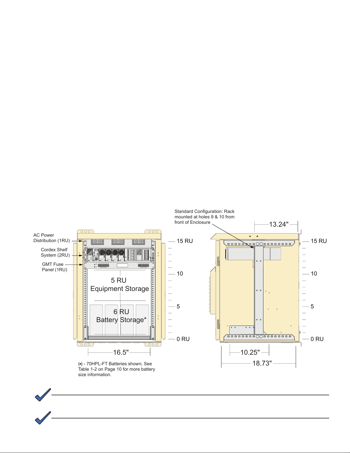
2.8
Equipment Installation, FBE2322-ENC
The FBE2322 Enclosure system's modular design and exibility allow for a wide variety equipment
installation options. A standard conguration example is shown below. Consult an Alpha Applications
Engineer for more details about approved congurations.
Standard Conguration Cordex with Battery Tray in Base Cabinet Example:
• AC Power Distribution Shelf
• Cordex™ CXRF-HP 48-1.2kW 19" Front Access Shelf System
- Congured for 120Vac input
- Provides 12.5A @ 48VDC, N+1
- Fully equipped shelf provides 2.4kW (12.5A max @ 48V)
- 2RU shelf
- Heat dissipation <154 BTU/hr, per rectier module
• Telect Dual Feed 60A GMT fuse panel, 10A/10B position -48VDC
• 5 RU of additional Equipment storage
• 6 RU of battery storage with FBE2322-ENC standalone.
Fig. 2-14, FBE2322-ENC Standard Equipment Conguration Example
NOTE:
Rack height is shown in Rack Units (RU); 1 RU = 1.75".
NOTE:
For wiring diagrams and alarm information, see Alpha p/n 031-314-08 Wire Diagram FBE2322 System.
Consult an Alpha Applications Engineer for further information about enclosure congurations.
27031-314-B0-001, Rev. A (12/2012)
Page 28

2.0 Installation, continued
0 RU
5
10
15 RU
0 RU
5
0 RU
5
10
15 RU
0 RU
5
11 RU Additional
Equipment Storage
18.73"
12.25" of
Battery Storage
Standard configuration: Rack
mounted at holes 9 & 10
from front of Enclosure
1 2 3 4 5 6 7 8 9 10
A
15A GMT Fuse Max
Power
Alarm
15A GMT Fuse Max
1 2 3 4 5 6 7 8 9 10
13.24"
Cordex Shelf
System (2RU)
GMT Fuse
Panel (1RU)
AC Power
Distribution (1RU)
2.9
Equipment Installation, FBE2322-ENCBEE
The FBE2322 Enclosure system capabilities may be expanded by adding additional enclosure sub-units.
A standard conguration example for that scenario is shown below. A standard conguration example is
shown below. Consult an Alpha Applications Engineer for more details about approved congurations.
Standard Conguration Cordex in Base Cabinet with additional Battery Enclosure Example:
• AC Power Distribution Shelf
• Cordex™ CXRF-HP 48-1.2kW 19" Front Access Shelf System
- Congured for 120Vac input
- Provides 12.5A @ 48VDC, N+1
- Fully equipped shelf provides 2.4kW (12.5A max @ 48V)
- 2RU shelf
- Heat dissipation <154 BTU/hr, per rectier module
• Telect Dual Feed 60A GMT fuse panel, 10A/10B position -48VDC
• 10 RU of additional equipment space, or
• BEE provides 12.25" for battery storage
28
Fig. 2-15, FBE2322-ENCBEE Stanrdard Equipment Conguration Example
031-314-B0-001, Rev. A (12/2012)
Page 29

2.0 Installation, continued
2.10
Battery Installation
WARNING!
Electrical shock can injure or kill. Remove any metallic personal items (rings, watches, etc.)
before working with batteries. Always use insulated tools. Only qualied personnel should
install batteries.
The FBE2322 Enclosure system allows for battery storage in the FBE2322-ENC. The following batteries will
t in the FBE2322-ENC with the installed 19" battery shelf:
• Enersys SBS B14F
• NorthStar HPL70
• NorthStar HPL115-FT
• NorthStar HPL220-FT*
For expanded equipment applications the FBE2322-BEE may be integrated with the enclosure system
or installed as a stand-alone unit. Up to 4 batteries may be installed in the BEE enclosure. Always follow
manufacturer’s specications for battery spacing. For Battery Specications see Page 10.
(*) - NorthStar HPL220-FT only available with the FBE-BEE enclosure.
StandardBatteryConguration:
1 2 3 4
Intercell Bars
-
+
-
+
Battery Terminal Covers
Inline Fuse
-
+
Fig. 2-16, Example of Battery Installation
-
+
To Cordex Shelf
-
+
Remote
Temperature
Sensors
29031-314-B0-001, Rev. A (12/2012)
Page 30

2.0 Installation, continued
2.10
Battery Installation, continued
Battery Wiring Procedure:
1. Place batteries in the enclosure with manufacturer’s
specied spacing between each battery.
2. Remove and save Battery Terminal Covers.
3. Connect adjacent batteries with Intercell Bar, see
Fig. 2-17. Where applicable install the Remote
Temperature Sensor.
4. Where applicable, install the Inline Fuse, (see
Fig. 2-18).
+
Fig. 2-17, Example of Battery
Stack Up
Fuse
Fig. 2-18, Inline Fuse Stack Up
-
Intercell bar
Remote Temp. Sensor
Flat Washer
Lock Washer
Nut (torque to
manufacturer's
specifications)
Bolt (torque to 75in-lbs
on fused terminal)
Flat Washer
Ring Terminal
Flat Washer
Lock Washer
Nut
5. Replace Battery Terminal Covers.
6. Make nal connections to equipment per
manufacturer’s recommendations.
7. Battery installation is now complete (see Fig. 2-19
for example).
Fig. 2-19, Example of Completed
Battery Installation
NOTE:
For further information for battery connections and wiring, see Alpha p/n 031-314-08 Wire
Diagram FBE2322 System.
30
031-314-B0-001, Rev. A (12/2012)
Page 31

3.0 Environmental Control Systems
3.1 FBE2322 Enclosure Environmental Control Overview
The FBE2322 Enclosure system has four integrated environmental control systems and an alternative
emergency backup system. The following options are available:
• Convection Cooling
• Fan & Filter Cooling
• AC Air Conditioning
• Heat Exchanger
• Emergency Fan (Optional for Air Conditioning/Heat Exchanger units)
The following sections provide further information for each environmental control option. For more
information about environmental systems not addressed in this manual, contact your Alpha sales
representative.
3.2 FBE2322 Fan & Filter Cooling
FBE2322 Fan Control Boards:
• 48VDC, DL Fan Control, 25-45C,W/SD, RMB (Alpha p/n 704-696-21)
• 24VDC, DL Fan Control, 25-45C,W/SD, FBE (Alpha p/n 704-696-31)
General operation:
Fans are off below 25ºC. Fans turn on at 25ºC and increases from 50% to 100% full speed with
increased enclosure temp from 25ºC to 45ºC. Over temp alarm is 55ºC. (Temp Tolerance +/- 2.5ºC).
Features:
• Two 118 CFM fans are powered by a variable speed temperature control. Fans turn off below
25ºC. Fans turn on at 25ºC and increase from 50% to 100% full speed with increased enclosure
temperature from 25ºC to 45ºC.
• Dual Fan Control PCBA has a green LED to indicate proper function, a red LED to indicate an alarm
condition and a push button test feature. When the button is pushed the fans will momentarily ramp
up to full speed and the alarm condition will be indicated. After this test sequence the fans will go
back to normal speed and the alarm will clear with green LED indicated.
• 24 or 48VDC input power.
• 5A fuse or circuit breaker is required (Not provided unless congured with Cordex shelf or GMT fuse
panel options).
• Maximum power draw for two fans is 20W.
• One form C dry contact alarm, open on alarm (Fan fail or 55ºC over temp, or LVD).
• Low Voltage Disconnect (LVD) input below 42VDC will shut off fans.
NOTE:
Cooling system alarm can be an indication that lters need to be cleaned or that fans may need to be
replaced. It can also indicate that the battery buss is low or the cooling system circuit breaker is off.
31031-314-B0-001, Rev. A (12/2012)
Page 32

3.0 Environmental Control Systems, continued
3.3 FBE2322 AC Air Conditioner
Theory of Operation:
The FBE2322 Enclosure AC Air Conditioner is an ICEQube1000V/ICEQube2400VXS. The air conditioner
is powered by a 120Vac 15A receptacle inside the enclosure. The ICEQube1000V draws 3.1A, and the
ICEQube2400VXS draws 7.1A.
The controller is located on the inside of the door and the digital display shows internal temp. The external
condenser fan turns on with the compressor when unit calls for cooling. There is a factory default off cycle
time delay of 3 ½ minutes on the compressor and condenser fan.
For more information see ICEQube Operation and Installation Manual. The air conditioner will maintain
enclosure temperature in cooling mode at the 25°C set point as long as cooling capacity is not exceeded.
In heating mode, the unit will maintain 10°C using a heating element mounted in the internal fan return air
stream. See Table 3-1 for Factory Default settings and Fig. 3-1 for control panel description.
NOTE:
The internal evaporator fan runs continuously.
FBE2322 AC Air Conditioner
Alpha Factory Default Settings
Cooling System ON Temperature 25°C (77°F)
Heating System ON Temperature 10°C (50°F)
High Enclosure Temperature Alarm 4 5°C (113°F )
Low Enclosure Temperature Alarm 0°C (32°F)
Audible Alarm OFF
Digital Display Temperature Units °C
Filter Maintenance Alarm Disabled
High Condenser Temperature Alarm (not adjustable) 76 .7° C (170 °F)
Table 3-1, FBE2322 AC Air Conditioner Specications
Programming
LED
ENTER PIN CODE
BEFORE PROGRAMMING
PGM
COOL HEAT ALARM FILT
STATUS
Display
Navigation Button
1
ADJUST
2
C
4
EXIT
3
SELECT
Parameter LEDs
SET TEMP
HI LO
SET ALARM
AUDIBLE
CODE
32
ButtonMode LEDs
Pin Code LED
Fig. 3-1, ICEQube AC Air Conditioner Control Panel
031-314-B0-001, Rev. A (12/2012)
Page 33

3.0 Environmental Control Systems, continued
3.4 FBE2322 Heat Exchanger
General Operation:
The heat exchanger moves the heated cabinet air into a network of closed loop vents that are in close
contact with closed loop vents with ambient air passing through them. This process transfers heat out of
the cabinet maintaining a constant internal temperature.
Features:
• Programmable variable speed DC fan controller with self-test.
• Internal fan: Off below 5ºC. On at 10ºC min speed; Variable to max speed between 20ºC to 35ºC.
• External Fan: Off below 15ºC. On at 20C min speed; Variable to max speed between 30ºC to 45ºC.
• High Temp alarm: 70ºC.
• Low Temp Alarm: -50ºC.
• Fan fail: Alarm contact loop open on alarm.
3.5 FBE2322 Emergency Fan
General Operation
When the primary cooling system cannot maintain adequate enclosure temperature, the emergency fan
thermostat closes energizing the emergency fan relay. This activates the form C dry contact alarm. The
high temperature alarm activates, the emergency air dampers open and the emergency fans turn on. Fan
air pressure pushes open the discharge air check valves and an electronic solenoid opens the air intake
damper.
Features:
• Two 118 CFM fans are powered by a variable speed temperature control. Fans turn off below
25ºC. Fans turn on at 25ºC and increase from 50% to 100% full speed with increased enclosure
temperature from 25ºC to 45ºC.
• Dual Fan Control PCBA has a green LED to indicate proper function, a red LED to indicate an alarm
condition and a push button test feature. During the test fans momentarily ramp up to full speed and
the alarm condition will be indicated. After this test sequence the fans will return to normal speed and
the alarm will clear with green LED indicated. Emergency fan solenoid does not have low voltage
disconnect (LVD) protection.
• One form C dry contact alarm, open on alarm.
Emergency Fan System Power Requirement:
• 24 or 48VDC input power.
• 3A fuse or circuit breaker is required (not provided unless congured with Cordex shelf or GMT fuse
panel options).
• 20awg input power leads provided (see wire labels for correct voltage and polarity).
• Maximum power draw 36W.
33031-314-B0-001, Rev. A (12/2012)
Page 34

4.0 Maintenance
4.1 FBE2322 Enclosure Maintenance
Monthly, visually inspect the enclosure for any mechanical damage that may allow insect or rodent
ingress into the enclosure. Ensure fasteners and hinges are tightened and in a state of good repair
(free from rust, damage, etc.). Inspect insect screens for damage and replace if necessary. Clear away
any windblown dust or insect debris from inside the cabinets. Inspect and maintain batteries per the
manufacturer's recommendations.
Annually ensure that all electrical components are operable and in good repair. Repair or replace any
component that shows excessive sign of wear or breakdown per the manufacturer's recommendations.
4.2 FBE2322 Environmental Control Maintenance
4.2.1 FBE2322 Air Filter Replacement
For fan cooled applications, the system has directional lters that should be inspected for
cleaning or replacement every six months depending on time of year or environment. Clean the
lters by back ushing with water in the direction indicated on the lter and reinstall the lter.
Filter placement is directional.
4.2.2 FBE2322 Heat Exchanger
The lterless design of the Heat Exchanger provides long-term low maintenance operation.
Occasional cleaning of the vent openings may be necessary to clear insects or windblown debris.
If further maintenance is required please Contact Alpha Technical Support.
4.2.3 FBE2322 AC Air Conditioner
Ambient Air Filter: It is recommended that the ambient air lter be inspected and cleaned
regularly, at least every 3 to 6 months, or more frequently depending upon ambient conditions.
Refer to the ICEQube Maintenance Manual for detailed information about maintaining the
Ambient Air Filter.
Condensate Management System: The condensate management system should be checked
periodically for scale, sludge and debris that may cause the drip outlet to clog. Maintenance
of the condensate management system will require removal of electrical power from the Ice
Qube system. Unplug the AC power cord from the 120Vac 15A receptacle within the enclosure
and ensure that the ICEQube system is disconnected from power. Follow all instructions in the
ICEQube Manual for cleaning the Condensate Management System before reconnecting the air
conditioner to the power receptacle.
Alpha mounts the Air Conditioner Filter bracket for security. Using pin-in-hex screws and orienting
the lter bracket opening toward the enclosure door prevents unauthorized removal of the lter.
See page 36 for instructions on changing the lter and/or reorient the bracket for convenience.
34
031-314-B0-001, Rev. A (12/2012)
Page 35

4.0 Maintenance, continued
4.2 FBE2322 Environmental Control Maintenance, continued
4.2.2 FBE2322 AC Air Conditioner, continued
Tools Required:
• 5/32" Hex w/ Pin Driver, Alpha p/n 964-027-10
Changing Filter/Filter Bracket Procedure:
1. Remove the (4) hex w/ pin security fasteners
(see Fig. 4-1).
2. If reinstalling for security, replace the lter and
reinstall the fasteners removed in Step 1. If
enclosure is within a secure location the lter
bracket may be reinstalled for convenient lter
replacement. Proceed to Step 3.
3. Rotate lter bracket so lter slides out away
from the door (see Fig. 4-2).
4. Reinstall fastners removed in Step 1 (see
Fig. 4-3).
5. The lter bracket has now been reinstalled
so the lter may be replaced without tools.
Fig. 4-1, Removing Security Fasteners
Fig. 4-2, Rotating the Filter Bracket
Fig. 4-3, Reinstalling the Filter Bracket
35031-314-B0-001, Rev. A (12/2012)
Page 36

4.0 Maintenance, continued
4.2 FBE2322 Environmental Control Maintenance, continued
4.2.2 FBE2322 AC Air Conditioner, continued
Changing Filter/Filter Bracket Procedure, continued:
6. Remove the lter by pulling the lter
tab. Replace lter, see Fig. 4-4.
Fig. 4-4, Removing and Reinstalling
the Filter
36
031-314-B0-001, Rev. A (12/2012)
Page 37

Page 38

Alpha Technologies Inc.
3767 Alpha Way
Bellingham, WA 98226
United States
Tel: +1 360 647 2360
Fax: +1 360 671 4936
Alpha Technologies Europe Ltd.
Twyford House Thorley
Bishop’s Stortford
Hertfordshire, CM22 7PA
United Kingdom
Tel: +44 1279 501110
Fax: +44 1279 659870
Alpha Technologies Ltd.
7700 Riverfront Gate
Burnaby, BC V5J 5M4
Canada
Tel: +1 604 436 5900
Fax: +1 604 436 1233
Toll Free: +1 800 667 8743
Alpha Technologies GmbH
Hansastrasse 8
D-91126
Schwabach, Germany
Tel: +49 9122 79889 0
Fax: +49 9122 79889 21
Alpha TEK ooo
Khokhlovskiy Pereulok 16
Stroenie 1, Ofce 403
Moscow, 109028
Russia
Tel: +7 495 916 1854
Fax: +7 495 916 1349
Alphatec Baltic
S. Konarskio Street 49-201
Vilnius, LT-03123
Lithuania
Tel: +370 5 210 5291
Fax: +370 5 210 5292
Alpha Technologies
Suite 1903, Tower 1,
33 Canton Road, Kowloon
Hong Kong City, China
Phone: +852 2736 8663
Fax: +852 2199 7988
Alphatec Ltd.
339 St. Andrews St.
Suite 101 Andrea Chambers
P.O. Box 56468
3307 Limassol, Cyprus
Tel: +357 25 375 675
Fax: +357 25 359 595
Visit us at www.alpha.com
Due to continuing product development, Alpha Technologies reserves the right to change specications without notice.
Copyright © 2012 Alpha Technologies. All Rights Reserved. Alpha® is a registered trademark of Alpha Technologies.
031-314-B0-001 Rev. A (12/2012)
 Loading...