

Page 1

950 -265 -10 Rev E (02/2 010)
Page 2

Cordex Controller Software
Version 2.0
034-136-B2
The following documents and drawings are included in this manual to provide the necessary information required for
routine operation:
• Program License Agreement: 048-556-10
• Operation Instructions: 034-136-C0
Alpha Technologies Ltd. 034-136-B2 Rev C WC
Printed in Canada. © 2010 Alpha Technologies Ltd. ALPHA and CORDEX are trademarks of Alpha Technologies Ltd. All Rights Reserved.
Page 3

CONTENTS
1 INTRODUCTION ............................................................................................................................................................. 4
1.1 Scope of the Manual ..................................................................................................................................... 4
1.2 User Interface (see Chapter 4) ..................................................................................................................... 4
1.3 Software Overview ........................................................................................................................................ 5
2 QUICK START ............................................................................................................................................................... 9
2.1 Applying Startup Power ................................................................................................................................. 9
2.2 Remote Communications (see Chapter 9) .................................................................................................... 9
2.3 Trouble-shooting Tips ................................................................................................................................... 9
3 STANDARD FEATURES ................................................................................................................................................ 10
3.1 Password Security ...................................................................................................................................... 10
3.2 Software Configuration Loading and Updates ............................................................................................ 10
3.3 Mixed Rectifier System ............................................................................................................................... 10
3.4 Safe Voltage ................................................................................................................................................ 10
3.5 Power Save ................................................................................................................................................. 10
3.6 Battery Temperature Compensation ........................................................................................................... 11
3.7 Battery Auto Equalization ............................................................................................................................ 12
3.8 Battery Monitor and Charge Current Control .............................................................................................. 12
3.9 Low Voltage Disconnect Operation ............................................................................................................. 13
3.10 Signals Management .................................................................................................................................. 13
3.11 Statistics and Historical Data ...................................................................................................................... 13
4 OPERATION ................................................................................................................................................................ 15
4.1 Startup and Reset Procedure ..................................................................................................................... 15
4.2 Normal Operation ........................................................................................................................................ 15
4.3 Mode Status (active area) and Temp Comp Indication .............................................................................. 17
4.4 Rectifiers (and Converters) Information (active area) ................................................................................. 21
4.5 Analog Signals Display (active area) .......................................................................................................... 22
4.6 Alarm Indication (active area) ..................................................................................................................... 23
4.7 Argus Icon (active area) .............................................................................................................................. 24
4.8 Date and Time (active area) ....................................................................................................................... 26
4.9 Saving Settings ........................................................................................................................................... 26
4.10 Overview of Web Interface .......................................................................................................................... 27
5 MENU NAVIGATION AND SAMPLE PROGRAMMING ........................................................................................................ 29
5.1 Menu Navigation ......................................................................................................................................... 29
5.2 Basic Programming Example ...................................................................................................................... 30
5.3 Advanced Programming .............................................................................................................................. 30
i
Page 4

6 MENU STRUCTURE, PROGRAMMING AND ADJUSTMENTS .............................................................................................. 32
6.1 System Info ................................................................................................................................................. 32
6.2 Converters ................................................................................................................................................... 35
6.3 Rectifiers ..................................................................................................................................................... 36
6.4 Batteries ...................................................................................................................................................... 39
6.5 Alarms ......................................................................................................................................................... 46
6.6 Signals......................................................................................................................................................... 58
6.7 Controls ....................................................................................................................................................... 78
6.8 Communications ......................................................................................................................................... 80
6.9 Hardware ..................................................................................................................................................... 83
6.10 Logs & Files (Web Interface only) ............................................................................................................... 84
6.11 Supervisor ................................................................................................................................................... 86
7 ADVANCED PROGRAMMING ........................................................................................................................................ 87
7.1 Example: Customize ................................................................................................................................... 87
7.2 Equation Builder Keypads ........................................................................................................................... 87
7.3 Tips on Programming .................................................................................................................................. 88
8 CXC COMMUNICATIONS MENU PARAMETERS .............................................................................................................. 89
8.1 Ethernet Port Configuration ........................................................................................................................ 89
8.2 PPP Connection Devices ............................................................................................................................ 90
8.3 Rear Port Configuration .............................................................................................................................. 91
9 REMOTE COMMUNICATIONS ........................................................................................................................................ 93
9.1 Establishing a Network Connection via a Crossover Cable ........................................................................ 93
9.2 PPP Serial Data Connection ....................................................................................................................... 94
9.3 Modem Connection ................................................................................................................................... 100
10 SIMPLE NETWORK MANAGEMENT PROTOCOL (SNMP) .............................................................................................. 102
10.1 Overview ................................................................................................................................................... 102
10.2 Network Manager MIB Files ...................................................................................................................... 104
10.3 Communication Configuration ................................................................................................................... 105
11 FACTORY RANGES AND DEFAULTS ........................................................................................................................... 109
12 MODBUS® COMMUNICATIONS PROTOCOL ................................................................................................................. 114
13 TROUBLE-SHOOTING ................................................................................................................................................ 120
13.1 Technical Support ..................................................................................................................................... 120
14 ALPHA CONVENTIONS .............................................................................................................................................. 121
14.1 Numbering System .................................................................................................................................... 121
14.2 Acronyms and Definitions ......................................................................................................................... 121
INDEX ............................................................................................................................................................................. 122
ii
Page 5

TABLES
Table A–Output channel assignments............................................................................................................................ 48
Table B–Digital input channel assignments ................................................................................................................... 50
Table C–Analog input channel assignments .................................................................................................................. 59
Table D–Controller signal default definitions .................................................................................................................. 62
Table E–Rectifiers menu defaults ................................................................................................................................. 109
Table F–Signals menu defaults .................................................................................................................................... 109
Table G–Batteries menu defaults ................................................................................................................................. 110
Table H–Converters menu defaults .............................................................................................................................. 110
Table I–Alarms menu defaults ...................................................................................................................................... 111
Table J–Controls menu defaults ................................................................................................................................... 112
Table K–Communications menu defaults ..................................................................................................................... 113
Table L–Hardware menu defaults ................................................................................................................................ 113
Table M–Supervisor menu defaults .............................................................................................................................. 113
Table N–CXC Modbus PDU address definition for function code 0x01 (read coils) .................................................... 114
Table O–CXC Modbus PDU address definition for function code 0x02 (read discrete inputs) .................................... 118
Table P–CXC Modbus PDU address definition for function code 0x03 (read holding registers) ................................. 119
Table Q–CXC Modbus PDU address definition for function code 0x04 (read input registers) .................................... 119
Table R–Trouble-shooting guide .................................................................................................................................. 120
iii
Page 6
1 Introduction
1.1 Scope of the Manual
This document describes the software features, on-site setup and operation of the Cordex System Controller
(CXC) from Alpha Technologies.
Refer to the Installation manual for hardware details.
1.2 User Interface (see Chapter 4)
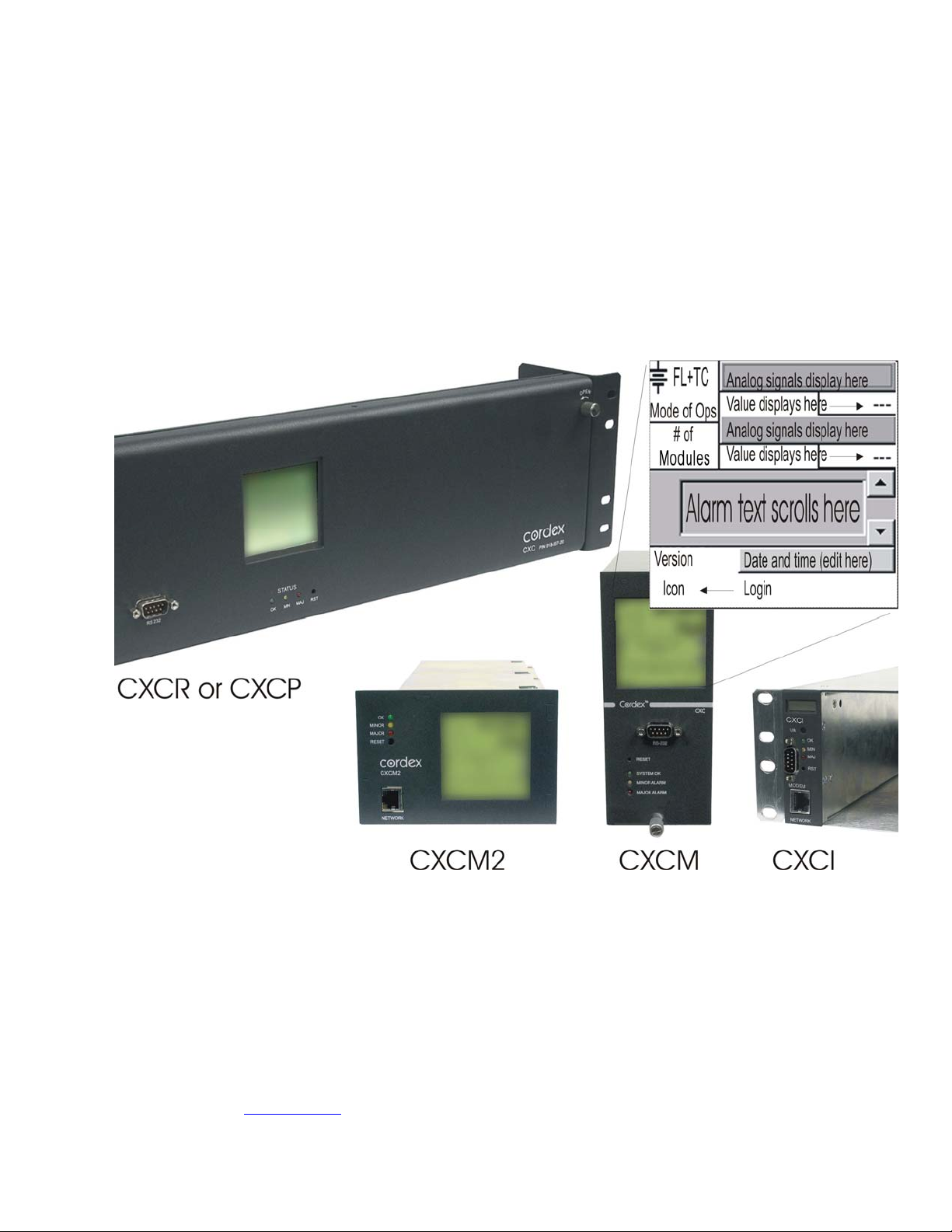
Located on the front panel of each CXCM (or CXCP or CXCR) model is a 160-x-160-pixel touch screen liquid
crystal display (LCD) similar to that used in a personal digital assistant (PDA), see Figure 1. This graphical user
interface (GUI) enables a person to interact with screen selectable items.
Refer to the back of this manual for Factory Service and Technical Support contact information
For CXC models with a touch screen
display, the use of a PDA type stylus is
recommended and may be required
when accessing the on-screen keyboard
for some adjustments.
Figure 1–CXC models showing features of main menu touch screen
The CXC will provide feedback during operation with different audible tones for alarms, invalid password, and
menu navigation.
NOTE: Other models, such as the CXCI, only have a 4-digit display for monitoring system voltage and current. Without a
touch screen display, system setup and management is performed exclusively with the web interface, see Section
4.10.
CAUTION
Do not connect anything other than the Alpha modem and Alpha-supplied DB-9 cable to the
D-sub port on the front of the CXCI.
A step by step connection wizard – provided to establish remote communications with the CXC – is available via
the Alpha website (www.alpha.ca
).
Alpha Technologies Ltd. 034-136-C0 Rev B WC
Printed in Canada. © 2010 Alpha Technologies Ltd. ALPHA and CORDEX are trademarks of Alpha Technologies Ltd. All Rights Reserved. Page 4 of 122
Page 7

1.3 Software Overview
The CXC software controls the entire DC power system. Features include temperature compensation, auto
equalization, remote access, battery diagnostics, and web server and SNMP support.
1.3.1 New Features since version 1.2
The following changes/updates have been incorporated into version 1.3 of the CXC software:
Communications Protocol Selection – enables the Supervisor to set the communications protocol for either the
Cordex series (CAN) or Pathfinder series (RS-485).
E-mail – enables communication of alarms via Ethernet or modem.
Enhancements to Battery Features – enables live Battery Discharge parameters to be viewable via Battery Log.
Enhancements to Event Logging & Statistics – provides tracking of several parameters on a daily basis, such
as battery current information.
Equation Builder for Custom Alarms & Signals – enables the Supervisor to program separate triggering
equations into the CXC software. The equations may reference any combination (up to 16) of the analog inputs,
digital inputs, virtual inputs, and alarms (such as Fan Fail) utilizing logical and arithmetic arguments that simulate
the functionality of a programmable logic controller (PLC).
Modem Support – expanded for web connections via PPP using modem (internal or external) with CXCP or
CXCR models.
Visit the Alpha website at www.alpha.ca for the latest manual and product downloads
Third Language Support – provides for multiple language files; which can be uploaded via web interface.
1.3.2 New Features since version 1.3
The following changes/updates have been incorporated into version 1.4 of the CXC software:
220Vdc System Support – enables the Supervisor to select the system voltage as 24V, 48V or 220Vdc.
CAN Communications Protocol – expanded to include Alpha’ new Cordex Shunt Multiplexer.
Web Interface Additions – provides submit (changes) button on top of every page, data logging, LVD countdown
timer, and relay text labels can be edited.
1.3.3 New Features (since version 1.4)
The following changes/updates have been incorporated into version 1.5 of the CXC software:
Urgent AC Mains Fail Alarm – provides indication of alarm condition. This major alarm has a time delay; the
default activation value is ten (10) minutes.
AC Phase Voltage Measurement – enables assignment (mapping) of rectifiers to a phase for individual phase
voltage readings.
SNMP Trap Dial-out – enables dialup connection from CXC to SNMP manager PC over intranet via corporate
intranet RAS (remote access server) port. This setup is similar to an e-mail RAS client.
1.3.4 New Features (since version 1.5)
The following changes/updates have been incorporated into version 1.6 of the CXC software:
CXCI Support – enables connectivity with Alpha’ new CXCI (controller used in small power Cordex integrated
rectifier systems) where system setup is performed with the CXC web interface alone.
IP Address Reset – provides a means to reset the IP address of a CXC without a touch screen display.
SNTP Support – enables synchronization of device time with an external source (see www.NTP.org
).
LCD Touch Screen Calibration – enables user to fine-tune the accuracy of the touch screen on site.
Default Values for Dynamic (Editable) Text Files – may be restored to factory settings.
Calibrate Analog Inputs – feature has been improved for web interface.
Alpha Technologies Ltd. 034-136-C0 Rev B WC
Printed in Canada. © 2010 Alpha Technologies Ltd. ALPHA and CORDEX are trademarks of Alpha Technologies Ltd. All Rights Reserved. Page 5 of 122
Page 8

1.3.5 New Features since version 1.6
The following changes/updates have been incorporated into version 1.7 of the CXC software:
12Vdc System Support – enables the Supervisor to select the system voltage as 12, 24, 48, 125 or 220Vdc.
Mixed Rectifier System – enables the use of one type of Alpha Pathfinder model rectifier working in pa rallel with
one type of Alpha Cordex model rectifier; e.g. PFM 48V-10kW with CXRF 48-3.6kW. The menu item Rectifier
Protocol is no longer required and has been removed.
Safe Voltage – enables the Supervisor to set the default system voltage (Safe Mode) in the event that
communications to Cordex rectifiers should fail.
Site Number – provides an additional line of text under Contact Information for convenient display of the Site
Number.
Rectifier Report Enhancements – provides new columns for device name and percentage of maximum output
current (per rectifier).
Battery Information – provides an additional window to enter/view the manufacturer’s data for the batteries in the
system; e.g., for inventory purposes.
Alarm Configuration Screen Enhancements – provides a list of all alarms in one place (via web browser). The
configuration of most alarms may be done on this one screen.
Alarm Tone – enables the Supervisor to enable/disable the audible alarm buzzer (tone).
Battery Test Alarm – provides a warning to indicate that a Battery Test is in progress.
Invalid Battery Voltage Alarm – provides for indication of invalid battery charging voltage; e.g., in the event that
the sense leads have become disconnected.
SNMP Enhancements – provides SNMP/Severity level (numeric) and enables CXC supervisor to set the
scheme.
AC Mains Voltage Correction – provides the means to apply a correction factor to the reading coming from the
rectifier.
ADIO Enhancements – enables the Supervisor to configure individual signals for an ADIO (Analog Digital Input
Output) Device; i.e., Cordex Smart Peripherals.
Custom Signal Units – enables the Supervisor to set the units value for Custom Signals; e.g., V, AH, mm, etc.
LVD DOD Control – enables the Supervisor to configure each LVD control for activation once the percentage of
Depth of Discharge (DOD) has increased above a threshold.
SNMP Community Settings – enables the Supervisor to configure CXC SNMP community settings.
SNMP Trap Recovery – enables the CXC SNMP agent to hold traps in a buffer during a network block out.
Event Notifications – Multiple SNMP and SMTP Destinations – enables the Supervisor to add up to eight (8)
separate destinations for SNMP and SMTP dial-out or e-mail notifications.
Test Relays – provides a message of warning to the CXC operator before allowing the toggling of an LVD relay
and allows the user to cancel the operation.
Argus MIB File Enhancements – provides separate object identifier (OID) for a ctive and cleared alarm traps.
Alarm status and signals are reconstructed into tables and sub tables to allow for future expansion while
remaining backward compatible with already defined alarms and signals.
Log File Cleanup – provides improved event log file management by filtering and condensing repetitive rectifier
events on a daily basis. File retrieval has been updated for sorting by name and by chronological order. The
display of log information has also been improved for ease of user navigation.
Passwords for Supervisor and User – provides two levels of password protection – the same password cannot
be used for both Supervisor and User.
Refer to the back of this manual for Factory Service and Technical Support contact information
1.3.6 New Features (since version 1.7)
The following changes/updates have been incorporated into version 1.8 of the CXC software:
Configuration File Enhancements – enables the Supervisor to exclude settings and groups of settings when
applying changes. A partial configuration file may be generated and sent to CXC (v1.81 and above).
CXCI Modem Support
– enables connectivity to the CXCI’s new front D-sub port with the Alpha modem and
Alpha-supplied DB-9 cable.
Alpha Technologies Ltd. 034-136-C0 Rev B WC
Printed in Canada. © 2010 Alpha Technologies Ltd. ALPHA and CORDEX are trademarks of Alpha Technologies Ltd. All Rights Reserved. Page 6 of 122
Page 9

1.3.7 New Features (since version 1.8)
The following changes/updates have been incorporated into version 1.9 of the CXC software:
Web Interface Facelift – provides more efficient access to software features. Speed/responsiveness has been
improved over previous version (testing has shown up to four times faster). Each page can be accessed
individually; for example, users with slow interfaces, such as modem, do not have to navigate to specific pages as
before.
Modbus® Support – enables CXC communication of alarms and live signals in RTU encoded data format using
Modbus protocol (messaging structure developed by Modicon®) upon query via TCP to any Modbus supervisor or
master.
Remote Battery Test Mode – enables the Supervisor to define a condition (custom alarm) that will force a
transition to battery test mode once the condition is met. BT mode stays active as long as the condition remains
true. This feature is exclusive for the Cordex series of rectifiers.
ADIO Support for 4R/8D I/O Module – allows configuration of this new module in the digital alarms or custom
alarm sections of the menus; where the alarm condition can be associated with a digital input and mapped to a
relay. The 4R/8D I/O module is a Cordex Smart Peripheral designed to expand the CXC I/O by four output relays
and eight digital inputs.
Temp Comp in EQ Mode (enable/disable) – allows the supervisor to enable or disable automatic battery
temperature compensation in equalize mode independently from float mode.
Boost Mode – provides the supervisor with the means to equalize charge the battery at a higher voltage relative
to the connected load. Activation is manual and certain conditions must be met to prevent damage to the load.
Visit the Alpha website at www.alpha.ca for the latest manual and product downloads
Custom/User Alarms – have increased in number from 5 to 20.
Battery Log – provides support for very slow discharges. This is accomplished by saving intermediate battery log
information in the event of controller power loss before battery recharge completes.
1.3.8 New Feature for version 1.93
ADIO Support for Cordex Battery Monitor System (BMS) – enables connectivity with Alpha’ new
BCMC module – a Cordex Smart Peripheral – designed to monitor a number of voltages, currents and
temperatures in battery strings via a number of remote devices that are managed through a ring data
network. Configuration is performed in the signals section of the CXC’s menus.
1.3.9 New Feature for version 1.95
Simplified BCT EQ Threshold – from rate of change to an absolute current value.
The BC Rate of Change setting used to be the rate of change of battery current in units of A/H. This
setting has changed and is now BC Threshold in units of A.
NOTE: When upgrading to v1.95 or later, users of the BCT EQ feature must re-evaluate the BC
Threshold setting and enter a new value since the units of the setting has changed.
1.3.10 New Feature for version 1.97
Cordex DC-DC Converter (CXD) Support – enables the Supervisor to configure converter settings,
display and read analog values; similar to the system controller features applied to the Cordex rectifier
series.
The converter defaults will be based on the system voltage if it is either 24 or 48Vdc.
NOTE: At present, the converter software does not support:
Two types of converters simultaneously
12, 125, and 220Vdc systems.
Other features include:
Active voltage control Firmware upgrade Loadsharing
Converter locate Inventory update Major and minor alarms
Alpha Technologies Ltd. 034-136-C0 Rev B WC
Printed in Canada. © 2010 Alpha Technologies Ltd. ALPHA and CORDEX are trademarks of Alpha Technologies Ltd. All Rights Reserved. Page 7 of 122
Page 10

1.3.11 New Features (since version 1.97)
The following changes/updates have been incorporated into version 2.0 of the CXC software:
Counters and Timers – counters enable the Supervisor to monitor the number of times a particular event occurs.
Timers are used to measure the amount of time since an event occurred or the amount of time between two
events. These features are suitable for general-purpose signals that can be used in Custom Signal or Custom
Alarm equations.
Dynamic Current Limit – enables the Supervisor to change the battery current limit based on the status of a
digital input; such as, when powering a system with a generator, to limit battery recharge current to prevent the
generator from overloading. See Dynamic Charge Current Control (CCC) feature.
ALCO Enhancements – enables the user to silence the alarms for a set duration (in minutes). The user may also
enable or disable cutoff of each of the following when ALCO is pressed:
Audible alarm
Alarm relays
E-mail
SNMP.
Printable Configuration (Config) – enables the user to print the total CXC configuration (for a particular
controller) via a Print button on the Logs&Files > Manage Configuration File page.
Equipment Inventory – a new User Inventory page allows the user to enter up to twenty inventory items.
Additionally, a System Inventory page enables the user to view a single list of all CAN connected devices, user
inventory items and battery information items. Previously, devices would only be shown on the individual category
pages; e.g., rectifiers connected shown on the Rectifier section.
Refer to the back of this manual for Factory Service and Technical Support contact information
SNMP Related Features – is comprised of these new items:
Add Trap Acknowledge (Inform)
CXC will wait for SNMP Manager (software) to acknowledge that it has received a trap. If the manager does not
acknowledge within a certain amount of time, the trap will be resent.
Timestamp Varbind
Data added to the SNMP trap to indicate the time of the event that triggered the trap to be sent.
Alarm Trigger Varbind
Data added to the SNMP trap that shows the analog value that triggered an alarm activation or deactivation.
Multiple Community Strings
The user may enter more than one set of SNMP community strings. This is to permit multiple SNMP NMS programs,
with different community strings, to connect to the CXC. A company with multiple NMS's, each in a different region,
with a different community string, will find it easier to connect to the CXC from various places.
Static Calibration – enables the Supervisor to calibrate Controller analog inputs and ADIO (except BCMC)
analog inputs without the need for a live signal at the input; especially useful for calibrating current inputs for
systems in the field.
Scheduler – enables the Supervisor to use the system time and date as operands in custom alarm and signal
equations.
Modbus® and SNMP – additions were made for converter alarms and signals.
1.3.12 New Features since version 2.03
The following changes/updates have been incorporated into version 2.04 of the CXC software:
The battery log will be closed off when 96 hours has elapsed since the start of the recharge cycle. This is
in addition to the existing functionality that closes off the log when the returned AH reaches 115% of the
rated capacity during the recharge cycle.
Improved response of charge current control when lithium-ion batteries are installed. Lithium-ion batteries
are detected by scanning the battery information and looking for the keyword “lithium” or “li-ion” in the
model comment fields.
The rectifier start delay algorithm now allows a setting of 0 s instead of the former minimum of 1 s.
Alpha Technologies Ltd. 034-136-C0 Rev B WC
Printed in Canada. © 2010 Alpha Technologies Ltd. ALPHA and CORDEX are trademarks of Alpha Technologies Ltd. All Rights Reserved. Page 8 of 122
Page 11

Visit the Alpha website at www.alpha.ca for the latest manual and product downloads
2 Quick Start
2.1 Applying Startup Power
1. Initiate startup routine by applying power to the CXC; e.g. close battery breaker or close converter and
rectifier input and output breakers.
NOTE: The CXC will perform a short self-test as it boots up. Alarm alerts are normal. The LEDs perform a scrolling
pattern to indicate there is activity. Please wait.
2. Check and adjust alarms and control levels in the CXC’s submenus.
3. Check and adjust group settings in the CONVERTERS and RECTIFIERS submenus; e.g. float, equalize
voltage, etc.
4. Verify COMMUNICATIONS settings as needed.
5. Program the CXC’s TEMP COMP and AUTO EQUALIZE settings as needed.
6. Test relay OUTPUT ALARM\CONTROLS as needed; e.g. Major Alarm, CEMF, etc.
2.2 Remote Communications (see Chapter 9)
The CXC can be set up, monitored and tested with a RS-232 serial data connection, ETHERNET 10/100 Base-T
or over a phone line using a modem. Some standard scenarios are described below:
Network (TCP/IP secured by user) to CXC rear Ethernet port.
Computer to CXC via RS-232 serial data connection (PPP) using a null modem cable connected to the Craft
port (front panel RS-232).
Laptop to CXC via direct Ethernet connection using a standard crossover cable.
External modem to CXC via RS-232 serial data connection using a straight through cable connected to the
rear RS-232 port.
Internal modem (see ordering options).
CAN bus (located next to the Ethernet port) is provided for connection to the Cordex series of converters and
rectifiers.
RS-485 bus provides a secondary connection for products (e.g., Pathfinder rectifiers) that do not support the CAN
bus interface.
2.3 Trouble-shooting Tips
See Trouble-shooting chapter for more information.
2.3.1 Converter and Rectifier Tips
The Cordex Converter (CXD) Rectifier (CXR) series modules are plug and play. When a CXD or CXR module is
added to the system, the CXC will detect and update the inventory automatically.
If CXD or CXR module communication has failed, or a module has been removed from the system, an
INVENTORY UPDATE
For the Pathfinder series of rectifiers, ensure that the:
Rectifiers are in NORMAL OPERATING MODE
REMOTE ACCESS is ENABLED
REMOTE ADJUST is ENABLED
BAUD RATE is set to 9600 baud.
2.3.2 Cordex Controller Tips
Use the CXC GUI (Section 4.2) or web interface (4.10) to ensure that the operating levels (e.g. input/output
voltage, converter voltage, etc.) are within operating parameters of alarm and control thresholds.
1
must be initiated manually.
1
Should Inventory Update fail: a) check cable & connections; b) check settings under System Info/System Configuration for correct voltage.
Alpha Technologies Ltd. 034-136-C0 Rev B WC
Printed in Canada. © 2010 Alpha Technologies Ltd. ALPHA and CORDEX are trademarks of Alpha Technologies Ltd. All Rights Reserved. Page 9 of 122
Page 12

Refer to the back of this manual for Factory Service and Technical Support contact information
3 Standard Features
The CXC provides centralized setup, control and monitoring of a communications power system.
3.1 Password Security
Two levels of password security are available: User and Supervisor. The same password cannot be used for both.
User access (Section 4.7.1) enables navigation through menus, but no changes are permitted.
Supervisor access enables navigation and changes to parameters including Supervisor password, see 6.11.1.
The Supervisor may change the User password only via the web interface.
3.2 Software Configuration Loading and Updates
Factory software updates and adjustments to the configuration file are possible through the RS-232 serial port or
Ethernet connection. The Supervisor may exclude settings and groups of settings when applying changes. A
partial configuration file may also be generated and sent to CXC (v1.81 and above).
3.3 Mixed Rectifier System
The CXC enables the use of one type of Alpha Pathfinder model rectifier working in parallel with one type of
Alpha Cordex model rectifier; for example, PFM 48V-10kW or PFM 48V-3kW with CXRF 48-3.6kW. Another
example is PFM 24V-3kW with CXRF 24-3.1kW. The menu item Rectifier Protocol is no longer required and has
been removed. The load share of each rectifier is based on the percentage of maximum output current of the
rectifier; see Rectifier Report (4.4.2). In some cases, e.g. battery test algorithm, the system functionality will be
limited to that of the Pathfinder rectifiers while the communications will equal that of the Cordex controller.
NOTE: The Pathfinder rectifiers will not be shown under Upgrade Firmware as that submenu applies to Cordex rectifiers
and smart peripherals only.
3.4 Safe Voltage
Safe Voltage is the voltage that the rectifiers will default to if the controller fails. In general terms, the open circuit
voltage for VRLA batteries is determined to be a point where discharge or over charge will not occur.
The Supervisor can set the default system voltage (Safe Mode) in the event that communications to Cordex
rectifiers should fail. This feature has a time delay (a function of the rectifier); the activation value is five (5)
minutes. The rectifier manual lists the default parameters.
3.5 Power Save
This feature will enable the Supervisor to improve operational efficiency when conditions warrant by running only
the necessary number of rectifiers. For example, when the load is significantly less than the available system
power, the controller will shut down one or more of the rectifiers so that the remaining rectifiers may operate with
greater efficiency at a higher current level. A short (one-minute) time delay or hysteresis is included to avoid
nuisance alarming and to eliminate changes if the load is fluctuating.
In addition, with Power Save, rectifiers are rotated into use on a weekly basis to share the service time.
When Power Save is enabled, it takes effect when a minimum discharge or load current (~2.5% of maximum
current of one rectifier) is achieved.
Charge or battery current limit calculations are made based on rectifiers that are running.
The Power Save feature is suspended during Battery Test mode, see 4.3.4.6.
NOTE: The remote shutdown setting (Cordex series only) enables the function in the rectifier. The Power Save feature
uses this functionality when a Cordex rectifier is commanded to shut down.
The Power Save feature does not work with the Alpha RSM 48/100 series of rectifiers.
Alpha Technologies Ltd. 034-136-C0 Rev B WC
Printed in Canada. © 2010 Alpha Technologies Ltd. ALPHA and CORDEX are trademarks of Alpha Technologies Ltd. All Rights Reserved. Page 10 of 122
Page 13

3.6 Battery Temperature Compensation
The automatic battery temperature compensation (Temp Comp or TC) will function with Cordex series rectifiers
that support CAN bus communications and Pathfinder series rectifiers that support RS-485 remote
communications.
Temp Comp may be active in either float (4.3.1) or equalize (4.3.2) mode.
Temperature inputs are available on the CXC for monitoring a lead acid battery string. Temperature sensor
readings can be displayed on the GUI in either Celsius (°C) or Fahrenheit (°F) scales.
The CXC will have the flexibility to display the breakpoints in voltage as well as temperature, also enabling them
to be entered as voltage or temperature.
The detection of thermal runaway will be limited to a programmable Battery Over Temperature Alarm. This will
enable the Supervisor to select a temperature that will trigger an alarm.
3.6.1 Theory of Battery Temperature Compensation
Battery life expectancy and performance is directly related to battery ambient temperature. The optimum
temperature for battery operation is 25°C (77°F). Without compensation, battery life is seriously compromised at
temperatures above 25°C, while battery performance is reduced below it.
Adjusting the battery’s float or equalize voltage to correspond with temperature fluctuations will ensure maximum
battery performance and life expectancy. With the CXC, this may be accomplished by using the software’s built-in
automatic temperature compensation function.
Visit the Alpha website at www.alpha.ca for the latest manual and product downloads
This function works by adjusting the system, every ten minutes, as the temperature changes and provides for a
maximum voltage change of 0.1V over this interval.
While this may seem like a small voltage change, even if the battery had a temperature compensation slope as
high as 5.5mV per C, the CXC would still be able to track a temperature change in the battery of up to 4.5C or
8F per hour. Due to the large thermal mass of the battery string, even an extreme rise or drop in environmental
temperature would be very unlikely to cause this kind of temperature change in the battery over a one hour
period.
Temp Comp occurs at standard rates commonly referred to as slope-compensation settings. For maximum
performance, it’s important to match the battery slope compensation with the setting recommended by the battery
manufacturer. This is not to be confused with slope regulation; which refers to the process of regulating current
among a group of parallel-operating rectifiers.
The Temp Comp feature has programmable breakpoints. These are the points at which Temp Comp will cease.
Further temperature decreases or increases will NOT increase or decrease the output voltage. This protects the
connected load from excessive voltage conditions. As Temp Comp is active in either float or equalize mode,
breakpoints should be set with this in mind.
The Temp Comp feature also incorporates fail-safe circuitry to prevent it from driving the rectifier system to a
voltage higher than is suitable for the load or battery.
3.6.2 Operation of Battery Temperature Compensation
The CXC can accommodate up to four sensors for lead acid battery temperature monitoring. If more than one
probe is used and the temperature readings are within 5°C (9°F) of one another, the temperature readings will be
calculated for the average. If the readings difference exceeds 5°C, it is assumed that thermal runaway is
occurring in one battery string and the calculation changes from average to the highest reading. If any reading is
suddenly outside the norm (i.e. cut leads or open leads), that reading is discarded and the associated Temp
Sensor Fail alarm is issued. The temperature calculation will then return to the average of the remaining sensors,
or next highest reading.
Temp Comp has been programmed as a low priority item; all commands and operations will take precedence
over Temp Comp. If a command is issued during a Temp Comp cycle, the cycle will be put on hold until the
command is completed. If any operation is happening when the Temp Comp cycle occurs, the cycle will be put on
hold until the operation is completed. Temp Comp will resume when the command or operation is completed.
The Temp Comp feature can be enabled or disabled in the CXC’s Batteries menu.
Alpha Technologies Ltd. 034-136-C0 Rev B WC
Printed in Canada. © 2010 Alpha Technologies Ltd. ALPHA and CORDEX are trademarks of Alpha Technologies Ltd. All Rights Reserved. Page 11 of 122
Page 14

3.7 Battery Auto Equalization
Auto Equalize (Auto-EQ) is a protective feature designed to ensure optimal lead acid battery life and performance.
With the CXC, auto equalize is used for two basic purposes: first, for providing a quick battery recharge after an
AC power failure, and second, as a long-term battery maintenance solution.
Refer to the battery manufacturer’s recommendations for equalization charging.
3.7.1 Battery Charge Auto Equalize
Battery Charge Auto Equalize can be used after a prolonged AC power failure, when the battery voltage has
decreased to a low level.
Once the batteries have decreased beyond the auto equalize low voltage threshold, the CXC will enter an armed
mode. When AC power returns, the system voltage begins to increase, which charges the batteries.
Once the system voltage increases to the high voltage threshold, the CXC enters the equalize mode and begins
to equalize charge the batteries for a period specified by the Supervisor in the AUTO-EQ DURATION submenu.
This is done to ensure the EQ duration is not effectively reduced by the time it takes to recharge the battery back
to the nominal system voltage.
3.7.2 Periodic Auto Equalize
Periodic Auto Equalize can be used for maintaining the long-term integrity of a battery string. Over time, individual
battery cell voltages may vary greatly. As a result, to ensure that batteries remain in optimum condition, they
should be equalize charged at regular intervals. The CXC enables the Supervisor to program the time between
automatic equalize charging of the battery string in the AUTO-EQ INTERVAL submenu.
Refer to the back of this manual for Factory Service and Technical Support contact information
3.7.3 Battery Current Termination (BCT) Equalize
The BCT Equalize feature provides an alternative method of ending EQ mode early to prevent over-charging of
the battery. Once enabled, it will only be active when EQ mode is caused by a Charge Auto Equalize.
BCT EQ will terminate Charge Auto EQ when the battery current falls below the BC Threshold setting. Upon initial
activation of EQ mode – that is triggered by the Charge Auto EQ feature – the CXC will wait for one minute of
system stabilization time before monitoring the battery current for BCT EQ. After one minute, the battery current is
checked about once per second to see if the current has fallen below the BC Threshold.
When the battery current falls below the BC Threshold, and remains below the threshold for three seconds, the
EQ duration is replaced with the BCT duration. After this time, the system returns to FL mode.
3.8 Battery Monitor and Charge Current Control
The Battery Monitor feature enhances the CXC’s capability to provide information about the battery to the User.
Charge Current Control will help increase battery longevity by keeping the battery current to within specified limits.
Charge current to the battery during recharge will be limited to a value as programmed by the Supervisor. This
value will be derived from the battery manufacturer’s specification sheet and entered by the Supervisor.
A battery run time prediction will be performed while the battery is supplying power to the load. The CXC will
collect data to estimate the time it will take the battery to be drained. If the Battery Monitor feature is enabled and
the battery is sourcing current to the load, a time estimate appears in the Mode Status screen. Runtime estimate
is also available in the Analog Signals display, which can be enabled for display status in (SIGNALS)
CONFIGURE SIGNALS\CONTROLLER SIGNALS.
During an AC outage or Battery Test, data will be collected to calculate a capacity prediction. A capacity of 80%
means the battery is due to be replaced. The accuracy of this will improve as the battery undergoes more
discharge cycles.
Alpha Technologies Ltd. 034-136-C0 Rev B WC
Printed in Canada. © 2010 Alpha Technologies Ltd. ALPHA and CORDEX are trademarks of Alpha Technologies Ltd. All Rights Reserved. Page 12 of 122
Page 15

3.9 Low Voltage Disconnect Operation
Whenever the system parameters require that the LVD be activated, a 60-second countdown and audible warning
will commence. When the countdown reaches zero, the LVD will be activated. During this countdown, an icon on
the GUI may be pressed to evoke a prompt to inhibit LVD controls – activated by entering the Supervisor
password. There is a 10-minute time-out for this. See also LVD Inhibit 6.7.2.
3.10 Signals Management
The CXC enables the Supervisor to view and edit a signal equation of the selected signal. The Supervisor may
also configure custom signals; properties may be modified or disabled as required. All signals in the system can
be selected for a signal equation builder making it possible to combine logic conditions and analog values to
generate an alarm.
The Supervisor can select which Temperature Sensor (including any smart peripheral temperature sensors) is
enabled for Battery Temp Sensor Signal.
3.11 Statistics and Historical Data
The CXC is capable of tracking several statistical parameters on a daily basis; e.g., analog statistics or triggered
items (listed below), such as, battery log and event log, see Data Logging (web interface only), Section 6.6.3.
Data is stored in local memory and may be accessed via a web interface. The logged data is comma-delimited
such that it can be automatically viewable in rows and columns in MS Excel. The data is stored on a first-in-firstout basis.
Visit the Alpha website at www.alpha.ca for the latest manual and product downloads
3.11.1 Analog Statistics
All statistics, to a maximum of 90 records (one per day) contain a time stamp and date. Daily analog statistics
include the minimum, maximum and average of:
Load Voltage Load Current
Battery Voltage Battery Current
AC Mains Battery Temperature
Total Rectifier Current Average DC Voltage
Average AC Voltage Number of Acquired Rectifiers
Number of Sourcing Rectifiers Ten Custom Signals
3.11.2 Battery Log
A maximum of 40 records can be logged for battery statistics and events. The Battery Log contains the following:
Event Type Capacity Rating
Battery Test Start Time Depth of Discharge
Discharge Duration Time Capacity
Amp Hours Delivered Recharge Duration
Amp Hours Recharge Return Peukert Number
1-5 Max. Midpoint Deviation Discharge Data1
1-5 Max. Midpoint Deviation Recharge Data2
Battery Current/Average Battery Current Battery Temperature/Average Battery Temperature
Battery Voltage/Battery Test End Voltage Open Circuit Voltage
Battery Test Result
During a battery discharge, active battery log information is displayed in a row above the Battery Log. This
information is then no longer available after the battery has finished recharging.
The Battery Log also provides support for very slow discharges. This is accomplished by saving intermediate
battery log information in the event of controller power loss before battery recharge completes.
When a battery test (BT) is started by the remote BT feature, the battery log will show “Remote BT” in the Event
Type column.
Alpha Technologies Ltd. 034-136-C0 Rev B WC
Printed in Canada. © 2010 Alpha Technologies Ltd. ALPHA and CORDEX are trademarks of Alpha Technologies Ltd. All Rights Reserved. Page 13 of 122
Page 16

3.11.3 Event Log
In addition, the CXC can record up to 500 events. All events are stamped with the date and time. Some of the
events available include the following:
All alarm events (activation and deactivation),
Rectifier alarm details,
Any change of state of the digital inputs,
Other miscellaneous events; such as, rectifiers being turned off or on due to the Power Save feature.
3.11.4 Data Logging
This feature of the CXC web interface allows the user to perform complex/custom configurations of the data
gathered by the Alpha controller. Various ways of setting the log frequency/limit and start/stop triggers enables
greater management of the events for collection.
The data is stored in files showing the records associated with each for easy archiving and retrieval. File Save
Option enables a FIFO (first in first out) or “Stop when full” means of data collection.
Recommended size is up to seven signals and a maximum one thousand entries, as very large log files may not
be viewable. If the datalog screen comes up blank, the log is too large to be displayed.
Refer to the back of this manual for Factory Service and Technical Support contact information
Alpha Technologies Ltd. 034-136-C0 Rev B WC
Printed in Canada. © 2010 Alpha Technologies Ltd. ALPHA and CORDEX are trademarks of Alpha Technologies Ltd. All Rights Reserved. Page 14 of 122
Page 17
4 Operation
4.1 Startup and Reset Procedure
When the CXC is powered-up or reset, it will first perform a 15-second self-test before displaying the Cordex logo
and various identification messages. The three front-panel LED’s will illuminate temporarily, but will extinguish
after the system has finished its self-test. Next, the GUI will display the power system’s parameters during Normal
operating mode, see Figure 2.
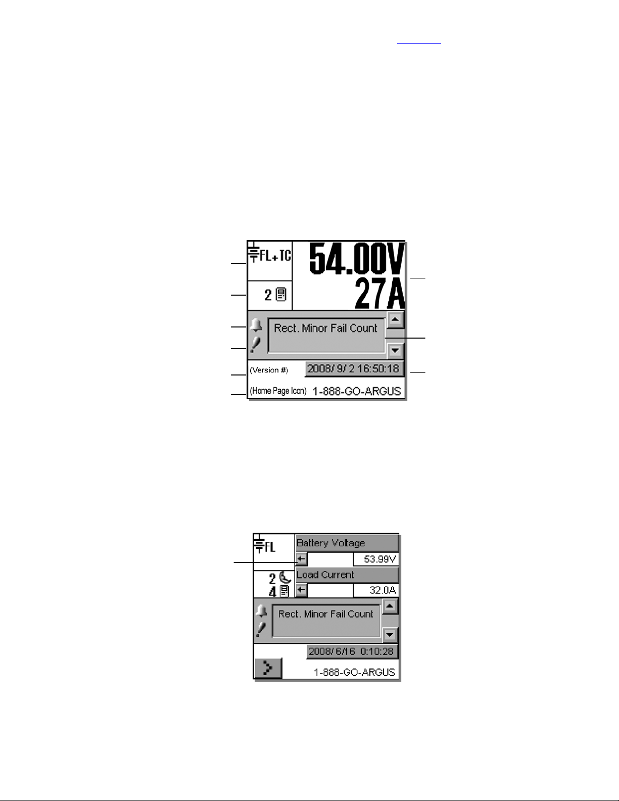
4.2 Normal Operation
This is the default-operating mode or “home page.” The GUI displays system status information and monitors all
input channels.
Active areas to tap and activate are noted below:
Mode Status
Rectifiers Information
Converter Report may also be accessed
via this active area
Alarm condition icon
Priority icon
Visit the Alpha website at www.alpha.ca for the latest manual and product downloads
Analog Signals Display
Alarm Indication
Home Page Icon, tap to login
4.2.1 Activation/Tapping
Each active area is touch sensitive and responds better to a stylus suited for this purpose; i.e. PDA type.
The Analog Signals Display on the home page will show two lines of text for system voltage and current by default
(Figure 2). Tap this active area to decrease the font size for four lines of text showing the system values and the
corresponding labels (Figure 3). The large font reappears after 20 minutes of inactivity (no user input); otherwise
tap again to enter a new window of operation (Figure 10) or select a different active area as required. Refer also
to 5.1.3.
The arrows beside the system values
enable the user to return to the larger font
of the normal (default) home page
The display also returns to the
default page when the user logs out
Software Version
Figure 2–Sample of CXC default operating screen
from the menu.
Date and Time
A new window of operation will open for the
active area selected, whereupon:
Buttons may be tapped to evoke
commands.
Lists or pull-down menus enable item
selection.
Sliders and scroll bars may be used
for navigation.
Pop-up windows may appear from
selected items; to be cleared as the
user follows the prompts.
Figure 3–Sample of CXC home page with user-activated Analog Signals Display
Alpha Technologies Ltd. 034-136-C0 Rev B WC
Printed in Canada. © 2010 Alpha Technologies Ltd. ALPHA and CORDEX are trademarks of Alpha Technologies Ltd. All Rights Reserved. Page 15 of 122
Page 18
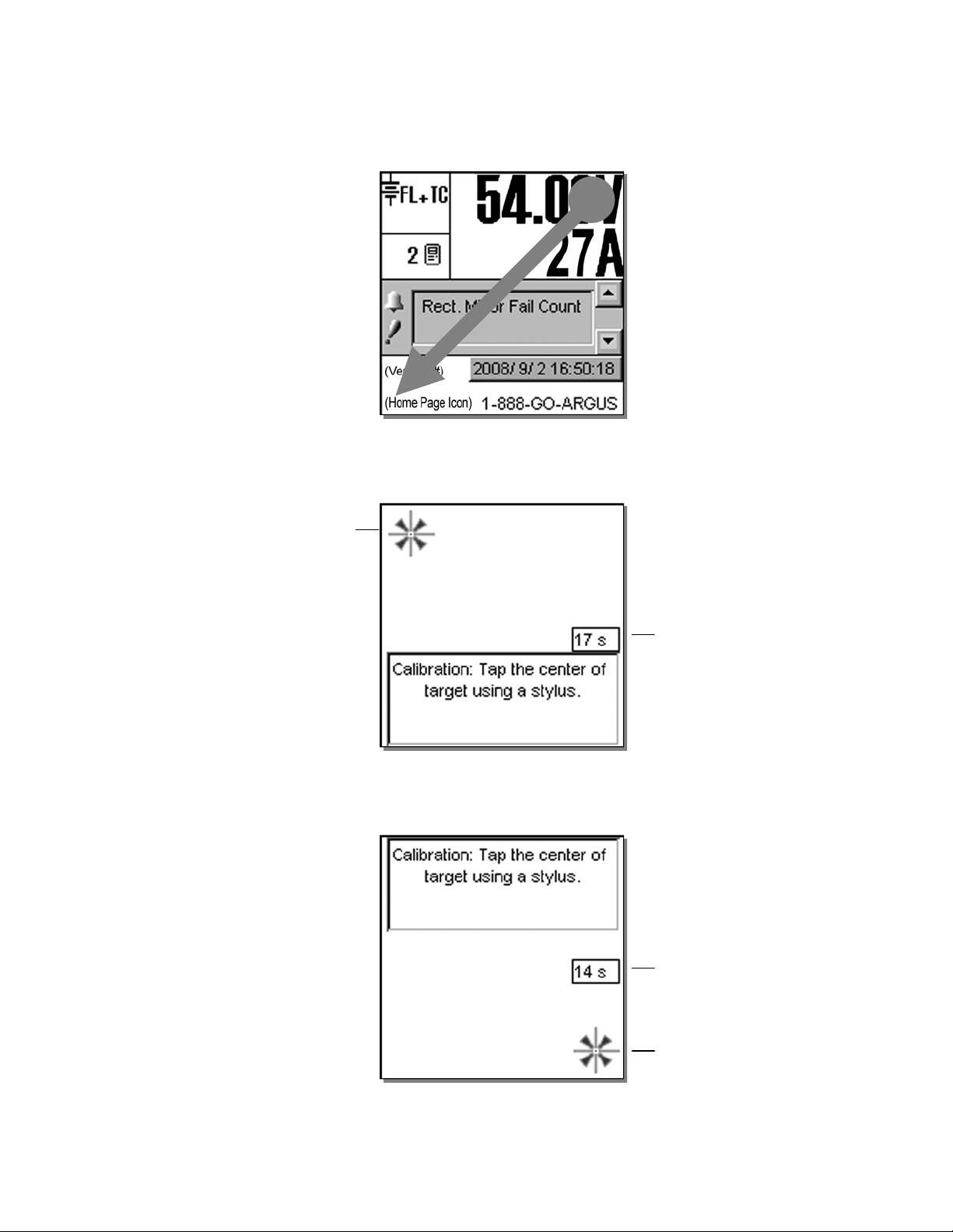
4.2.2 LCD Touch Screen Calibration
t
(
)
r
A touch screen calibration page may be evoked from the user interface default operating screen:
Perform a diagonal action or "swipe" from the top right area of the LCD to the bottom left area:
CAUTION: Do not use a pen, pencil o
other sharp object to tap on the CXC
screen. This will scratch the screen and
may void the warranty.
Figure 4–Begin LCD touch screen calibration (default operating screen)
When the calibration screen appears, tap on the center of the first target within 20 seconds to complete this step:
Refer to the back of this manual for Factory Service and Technical Support contact information
Tap on the center of the first targe
Calibration will be ignored if the user does
not tap in the general area of the target
(correct area is the size of the target icon)
top left area of the screen
Count down timer; calibration will be
ignored when time runs out
Figure 5– LCD touch screen calibration screen target one
Tap on the center of the second target (bottom right area of the screen) to complete the calibration:
If the user does not tap in the general area
of the first target, then calibration will not
be saved no matter what happens in the
second target
Count down timer; calibration will be
ignored when time runs out
Tap on the center of the second target
and calibration will be saved
automatically
Figure 6– LCD touch screen calibration screen target two
NOTE: Both the targets must be tapped correctly for the calibration to take effect. This is done to prevent the calibration
from changing dramatically from the default.
Alpha Technologies Ltd. 034-136-C0 Rev B WC
Printed in Canada. © 2010 Alpha Technologies Ltd. ALPHA and CORDEX are trademarks of Alpha Technologies Ltd. All Rights Reserved. Page 16 of 122
Page 19
Visit the Alpha website at www.alpha.ca for the latest manual and product downloads
y
4.3 Mode Status (active area) and Temp Comp Indication
The CXC has four modes of operation: float (FL), equalize (EQ), boost (BST) and battery test (BT). The mode,
along with temperature compensation (TC or Temp Comp) activation, is indicated in the top left “active area” of
the GUI, see Figure 2. The time duration, until the mode changes, will also be shown in that active area.
Tap this active area to enter a new screen, or window of operation, for mode selection, see Figure 7 below:
Mode (+Temp Comp) displa
Additional functions display here; such as,
countdowns and status of battery runtime
4.3.1 Float (FL) Mode
This is the CXC’s default mode at start up and during normal system operation. When in this mode, the rectifier’s
charge (or output) voltage is driven by the float voltage setting found in the CXC’s Rectifiers menu, see 6.3.2. The
icon (message) FL will display on the GUI’s upper left corner (Figure 2) when the CXC is operating in float mode.
Do not adjust the float voltage of the rectifiers when they are in Current Limit.
When operating in a mode other than float mode, tap the FL mode selection button to return to the defaultoperating mode. Tap the “check mark” button in the lower right corner of the GUI to verify the action and return to
the previous screen.
Mode Selection buttons
FL + TC
54.00V 250A
Battery Voltage Mode
FL EQ BT
Periodic Auto-EQ Disabled
Auto BT Disabled
BST
Figure 7–Mode selection screen
Battery Voltage and
Load Current display
Alarm Indication
Verify action and
return to previous screen
4.3.2 Equalize (EQ) Mode
The equalize mode is used to equalize charge a battery string. This mode can be selected via the Mode Status
active area and by tapping the EQ mode selection button or by sending an external command; e.g., via web
interface. When in this mode, the rectifier’s charge (or output) voltage is driven by the equalize voltage setting
found in the CXC’s Rectifiers menu, see 6.3.2. The EQ icon will display when the CXC is operating in equalize
mode.
A maximum time limit for equalize charging can be programmed to prevent accidental over-charge of a battery
string. This limit is determined by the setting found in the EQ Timeout menu, see 6.3.2.10. Do not adjust the
equalize level of the rectifiers while they are in current limit.
When operating in EQ mode, the text below the Mode Selection buttons (shown above) will display the time until
FL mode in hours. Tap the “check mark” button in the lower right corner of the GUI to verify the action and return
to the previous screen.
4.3.3 Boost (BST) Mode
This feature (see 0) provides the supervisor with the means to equalize charge the battery at a higher voltage
relative to the connected load. Activation is manual and certain conditions must be met to prevent damage to the
load.
A custom alarm must be created to include all the desired factors that must be taken into account before
activating BST mode. This mode will then only be permitted if the alarm is false.
Once activated, BST mode concludes with a timeout or whenever the status of the custom alarm is true and
reverts to FL mode. BST mode can also be cancelled if the conditions that are required in order to activate BST
mode have changed.
Alpha Technologies Ltd. 034-136-C0 Rev B WC
Printed in Canada. © 2010 Alpha Technologies Ltd. ALPHA and CORDEX are trademarks of Alpha Technologies Ltd. All Rights Reserved. Page 17 of 122
Page 20

Refer to the back of this manual for Factory Service and Technical Support contact information
4.3.4 Battery Discharge Test or Battery Test (BT) Mode
The battery discharge test is used to update the status of the lead acid battery capacity. BT can be set to run
automatically or can be initiated manually (via Mode Selection button).
4.3.4.1 Definitions
End/Terminal Voltage — The voltage at which the test will end or terminate.
Timeout — The maximum time the test will be permitted to run before it is aborted.
Period in Days — The time between each Auto-BT.
Battery On Discharge (BOD) Alarm — This alarm will indicate that the battery is discharging.
4.3.4.2 Manual Activation
The user can manually activate the test by tapping the BT mode selection button (Figure 7).
4.3.4.3 Auto-BT Feature
This feature will enable the CXC to start a test automatically on a periodic basis. The Supervisor
may enable or disable the feature in (BATTERIES) BATTERY TEST\AUTO-BT menu, see
6.4.5.2.
4.3.4.4 Tips on Using the BT Mode
Use Charge Current Control (6.4.3) to limit the battery recharge current to the battery
manufacturer’s specified maximum value.
The resultant battery capacity estimate will be more accurate if the test is started when the
battery is fully charged. If a recent discharge has occurred within the last 96 hours, when a
mode change to BT is selected, a dialog box will prompt the user to confirm the mode change.
During a test, the runtime hours will be accessible through the Analog Signals display or Mode
Status screen. The runtime hours will reflect the time remaining in the test.
The runtime will be displayed after the start of an outage and when a BOD condition is detected;
i.e., battery is sourcing current and voltage is below open circuit.
When a test is started by the remote BT feature, the battery log will show “Remote BT” in the
Event Type column.
The BT depth of discharge (DOD) can be accessed via the Analog Signals Display; provides an
additional indication of test progress.
BT information is available via the CXC’s battery log web page when a test is in progress. In
addition, the new battery capacity estimate can be accessed via the Analog Signals display at
any time before, during or after the test.
Alpha Technologies Ltd. 034-136-C0 Rev B WC
Printed in Canada. © 2010 Alpha Technologies Ltd. ALPHA and CORDEX are trademarks of Alpha Technologies Ltd. All Rights Reserved. Page 18 of 122
Page 21

Visit the Alpha website at www.alpha.ca for the latest manual and product downloads
4.3.4.5 BT Initiation
When the test begins, an entry will be made in the event log. If enabled, an alarm will provide a
warning to indicate that a Battery Test is in progress.
The test will continue, depending on the type of rectifier in use, in accordance with the following
algorithms (as applied to lead acid batteries):
Algorithm 1 — For rectifiers that support Battery Test (BT) mode:
1. A command is sent to put the rectifiers into BT mode.
2. BT mode runs for the period set as Timeout or until BT End Voltage is reached.
Algorithm 2 — For (Pathfinder) rectifiers that do not support BT mode:
1. Rectifiers are commanded to go to nominal voltage.
2. The rectifiers are periodically scanned to be sure that they do not begin sourcing
current. When 3% DOD is reached and the rectifiers are still not sourcing current, the
rectifiers are turned off.
3. The rectifier float setting is reset to the setting stored in the system controller.
4. When the system voltage reaches the end (termination) voltage or a timeout occurs, the
system controller will command the rectifiers to turn ON and enter FL mode.
4.3.4.6 Activity During BT Mode
Temp Comp and Power Save features are suspended during a battery test.
When the battery is discharging, a BOD alarm will be active.
During a test, the mode symbol in the upper left corner of the GUI will be similar to the FL mode
symbol except that the letters “FL” will be replaced with “BT.”
Runtime estimate begins at 3% DOD.
Capacity estimate also begins at 3% DOD, but will not be stored unless DOD > 20%; the point
at which reasonable accuracy can be assured.
4.3.4.7 AC Failure During BT Mode
If the AC fails during a battery test, the test will be aborted. This will place the rectifiers into a
state that will enable them to resume providing power to the load when AC returns. If the
Runtime is being displayed, it will continue to update.
4.3.4.8 Addition of Rectifiers During BT Mode
If rectifiers are added to the system when a battery test is active, they will be placed into the
same state as the other rectifiers. They will be:
Placed into BT mode (for rectifiers that support BT mode), or
Placed into remote shutdown, or
Set to the same voltage as the other rectifiers.
4.3.4.9 Conditions to Watch for During BT Mode
If the voltage drops below 47V before or when 3% DOD is reached, the test is aborted and the
battery capacity is set to 0% (resulting in a Battery Capacity Low alarm). This provides an
indication that the battery is very weak
or to the percentage of expected battery capacity before the next battery test is started, in order
for the battery monitor to again attempt to compute the battery capacity.
If rectifiers are seen to be sourcing current during the test and the battery ceases to be
discharging, the test is aborted.
4.3.4.10 Canceling BT Mode
BT mode can be cancelled by changing mode to FL or EQ.
2
. The battery capacity must be manually reset to 100%,
2
In some cases, incorrect battery parameters can cause this condition to occur with a good battery.
Alpha Technologies Ltd. 034-136-C0 Rev B WC
Printed in Canada. © 2010 Alpha Technologies Ltd. ALPHA and CORDEX are trademarks of Alpha Technologies Ltd. All Rights Reserved. Page 19 of 122
Page 22

4.3.4.11 Battery Discharge Test Completion
The test is considered complete once the battery begins to charge. This could be due to the test
ending from timeout, the system reaching the end (termination) voltage or an abort condition.
Once the battery begins to charge, the recharge cycle begins. Live battery recharge information
is available from the battery log web page.
4.3.4.12 Remote BT Mode
This feature will force a transition to BT mode when a user-defined condition (custom alarm) is
true.
When this condition is true, BT mode is entered regardless of the regular safety checks that are
performed during manual or automatic changes to BT mode. BT mode stays active as long as
the condition remains true.
A check box is used to enable/disable this feature. The default is disabled. If the condition is
true and the check box is disabled, then the system will be put into FL mode.
If the condition becomes false, disabled, invalid, or the (assigned custom alarm) equation is
empty, the system will be put into FL mode.
NOTE: This feature is exclusive for the Cordex series of rectifiers. If Remote BT is
active and a rectifier other than the Cordex series is added to the system then
Remote BT will be aborted.
Refer to the back of this manual for Factory Service and Technical Support contact information
Alpha Technologies Ltd. 034-136-C0 Rev B WC
Printed in Canada. © 2010 Alpha Technologies Ltd. ALPHA and CORDEX are trademarks of Alpha Technologies Ltd. All Rights Reserved. Page 20 of 122
Page 23
Visit the Alpha website at www.alpha.ca for the latest manual and product downloads
y
e
s
e
s
s
e
4.4 Rectifiers (and Converters) Information (active area)
Tap this active area, located below Mode Status on the “home” page (Figure 2), to enter a new window of
operation for converter/rectifier updates and reports, see Figure 8 below:
Mode (+Temp Comp) displa
Select operation her
4.4.1 Inventory Update
This button will enable the user to re-acquire all the attached modules to the CXC; to verify the existence of all
connected modules. Tap to evoke this command (and return to the home page).
A pop-up window (not shown here) will appear over the home page to show a progress bar of the number of
modules acquired during the update that has just been evoked. Tap the “X” button to clear the pop-up from the
active area.
Inventory update must be done whenever a module is removed from the system. The system is polled with
respect to the following scenarios:
FL + TC
54.00V 250A
Battery Volts and
Load Current display
Alarm Indication
Inventory Update
Rectifier Report
Converter Report
Return to previous screen
Figure 8–Update (inventory) and report selection screen
Module has failed and is no longer able to communicate, or
User has removed a module from the system.
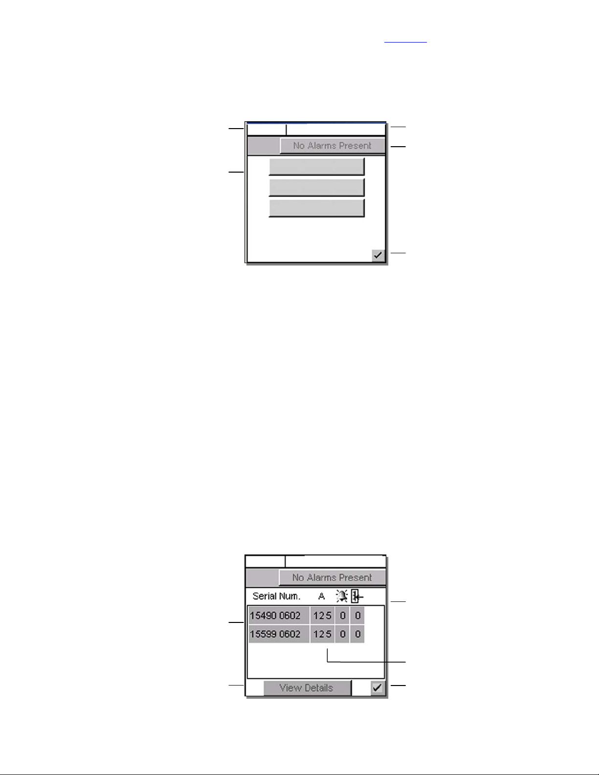
4.4.2 Rectifier Report (Converter Report similar)
This button (or menu item in 6.3.1) will enable the user to view, in a list (report), all of the acquired modules in the
system. Tap to evoke this command.
A new active area will be displayed, see Figure 9 below. The first column lists the serial numbers of the modules.
The report then displays the current output (A) of each module (or toggle for % of maximum output) and the
number of active alarms (if that module is issuing an alarm). The rightmost column displays the number of
settings out of tolerance (OOT per web interface).
FL + TC
Select module to view detail
Tap View Details to produc
a new window with pull-down menu
showing all of the alarms and setting
that are out of toleranc
Figure 9–Rectifier (or Converter) report screen
54.00V 250A
Report headings for serial number,
current display (% or A), number of alarms
and settings out of tolerance (OOT)
A value of ‘---‘ indicates Comms Lost
Return to previous screen
Rectifier (or Converter) Locate Feature — Once a module is selected, the (module) LED’s will start flashing.
Alpha Technologies Ltd. 034-136-C0 Rev B WC
Printed in Canada. © 2010 Alpha Technologies Ltd. ALPHA and CORDEX are trademarks of Alpha Technologies Ltd. All Rights Reserved. Page 21 of 122
Page 24
4.5 Analog Signals Display (active area)
y
s
d
d
Tap this active area3, top right of the “home” page (Figure 2), to enter a new window of operation for analog
signals display and configuration, see Figure 10 below:
Mode (+Temp Comp) displa
Pull-down menu (heading) also includes:
Analog Inputs, Digital Inputs,
Rectifier Signals, Custom Signals,
Converter Signals, Counter,
Timers, ADIO Signals
Change heading to acces
menu item desire
Tap to edit selected menu item
User will be prompted for passwor
Figure 10–Analog signals display screen
The item selected from the analog signals active area will now be the highlighted item listed in the new window.
The pull-down menu enables the user to select the signal group; signal items are listed below the group heading.
Navigate the menu list to select the desired item.
FL + TC
Load Current 250
Battery Voltage 54.00
Battery Current 5.4
Refer to the back of this manual for Factory Service and Technical Support contact information
54.00V 250A
Battery Volts and
Load Current display
Alarm Indication
Controller Signals
Sliders and scroll bars
are used for navigation
Select menu item to configure
Configure
Accept changes and
return to previous screen
4.5.1 Controller Signals
Once a menu item is selected, tap the “Configure” button to produce another window and list of items to navigate,
see 6.6.2. To edit items, the User will be prompted for a password (via a pop-up window).
4.5.2 Analog Inputs
Once a menu item is selected, tap the “Calibrate” button to produce another window and list of items to navigate,
see 6.6.1. To edit items, the User will be prompted for a password (via a pop-up window).
4.5.3 Digital Inputs
Under this menu heading, the user can view the list of digital inputs, see Table B.
4.5.4 Rectifier Signals
Under this menu heading, the user can view the list of rectifier signals, see Table E.
4.5.5 Custom Signals
Once a menu item is selected, tap the “Configure” button to produce another window and list of items to navigate.
To edit items, the User will be prompted for a password (via a pop-up window).
4.5.6 Converter Signals
Under this menu heading, the user can view the list of converter signals, see Table H.
4.5.7 Counter
Once a menu item is selected, tap the “Configure” button to produce another window and list of items to navigate.
To edit items, the user will be prompted for a password (via a pop-up window).
4.5.8 Timers
Once a menu item is selected, tap the “Configure” button to produce another window and list of items to navigate.
To edit items, the user will be prompted for a password (via a pop-up window).
4.5.9 ADIO Signals
Under this menu heading, the user can view the live data from an ADIO device (i.e., Cordex Smart Peripherals)
connected to the CXC. Refer also to Section 6.6.2.6, Example Four.
3
When labels are not shown, digits are displayed two rows high. See Figure 2 for Normal Operation. Tap to minimize (see Figure 1) and tap again to
enter new window of operation.
Alpha Technologies Ltd. 034-136-C0 Rev B WC
Printed in Canada. © 2010 Alpha Technologies Ltd. ALPHA and CORDEX are trademarks of Alpha Technologies Ltd. All Rights Reserved. Page 22 of 122
Page 25
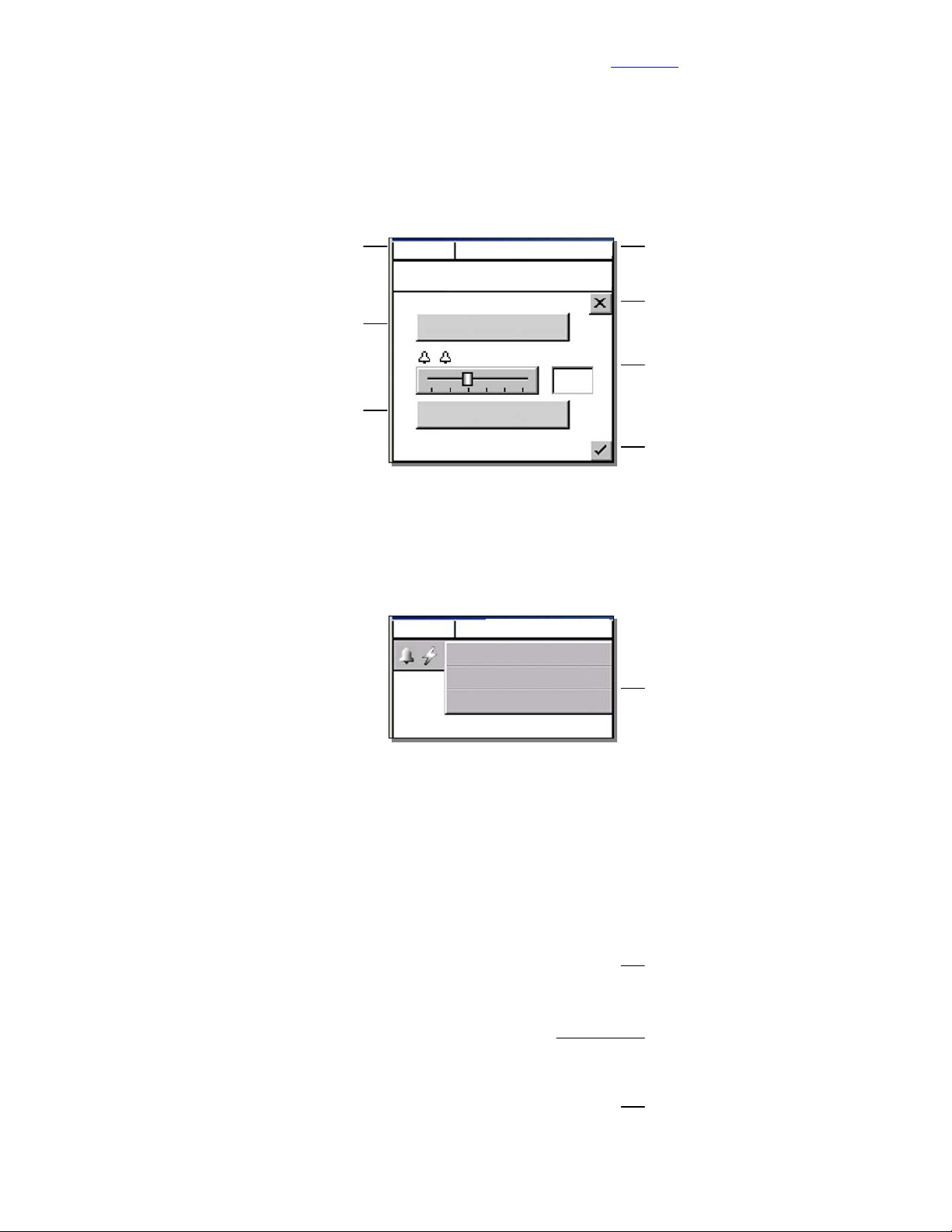
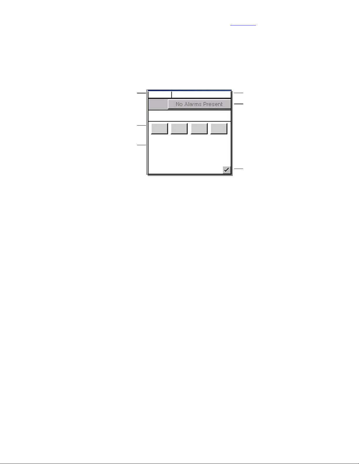
4.6 Alarm Indication (active area)
y
y
s
Within the default operating screen, the Alarm Indication window may show icons on the left margin to indicate
various alerts (such as an active alarm and priority of the condition). In the middle of the window, text will scroll
indicating alarm notification or status. Navigation keys (on the right) aid the user to view the text.
Tap this active area, located below Analog Signals Display on the “home” page (Figure 2), to enter a new window
of operation for alarm display and configuration, see Figure 11 below:
Visit the Alpha website at www.alpha.ca for the latest manual and product downloads
Mode (+Temp Comp) displa
Tap to silence active alarm
Tap to view alarm histor
4.6.1 Cutoff All Alarms
Tap “Cutoff All Alarms” (button shown above) to silence active alarms. In addition, on any screen where the
alarm indication is shown (as in previous figures), the User may tap the alarm indication “button” to display a pulldown menu (Figure 12 below) for alarm cutoff (also known as ALCO, see 6.5.1):
FL + TC
54.00V 250A
Alarm will scroll here...
Cutoff All Alarms
Scroll Rate
1 s
Show Alarm History
Figure 11–Alarm indication display screen
FL + TC
54.00V 250A
Alarm displays here
Cutoff All Alarms
Cancel
Battery Volts and
Load Current display
Discard changes and
return to previous screen
Use slider to change alarm scroll rate
Accept changes and
return to previous screen
Use pull-down menu to cutoff all alarms
Figure 12–Alarm cutoff pull-down menu
Use pull-down menu to select priority,
either major, minor, message, or all
Alarms will display here in a list
Verify action and return to previous screen
Alpha Technologies Ltd. 034-136-C0 Rev B WC
Printed in Canada. © 2010 Alpha Technologies Ltd. ALPHA and CORDEX are trademarks of Alpha Technologies Ltd. All Rights Reserved. Page 23 of 122
Page 26
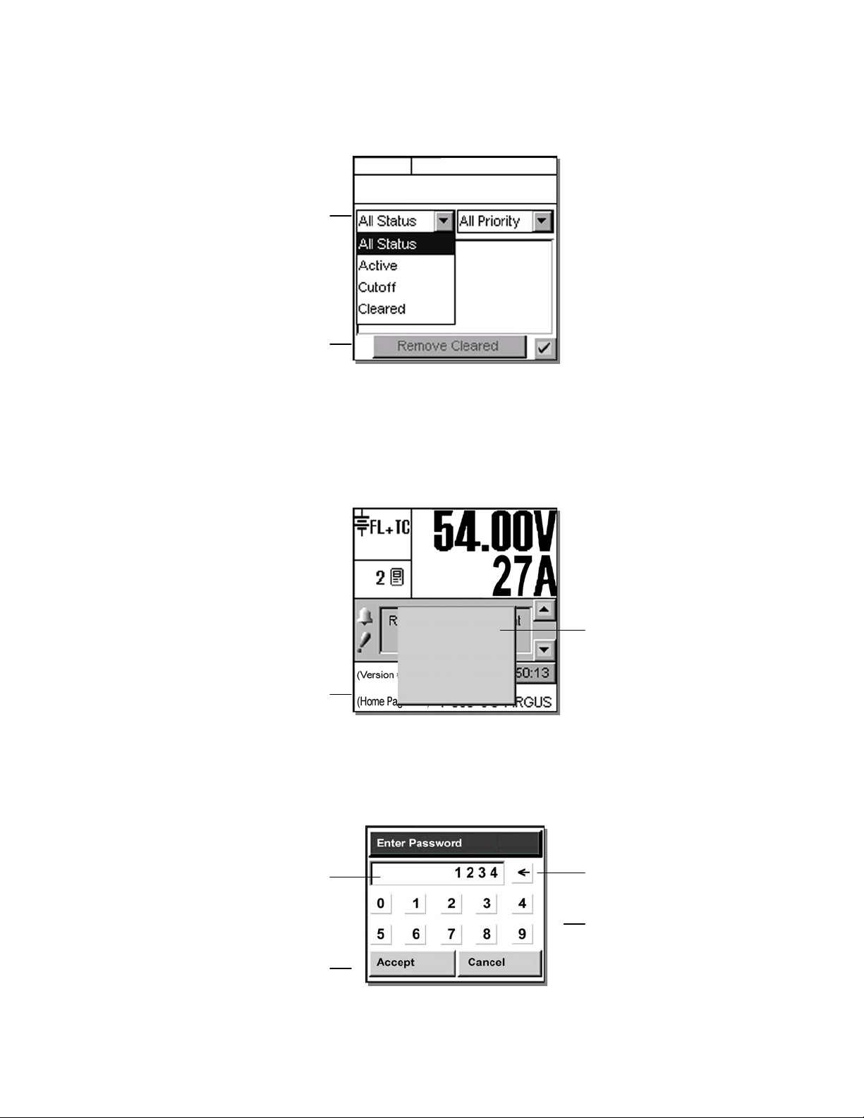
4.6.2 Alarm History
n
l
s
y
Tap “Show Alarm History” to enter another screen that will list past alarms. Two pull-down menus enable
the user to select which alarms will be displayed according to status and priority, see Figure 13 below:
Refer to the back of this manual for Factory Service and Technical Support contact information
Use pull-down menu
to select status as shown
Tap to “Remove Cleared” alarm
from displa
4.7 Argus Icon (active area)
Tap the Argus icon at the lower left of the “home” page to login (password entry), adjust contrast of display, reset,
and select language, see Figure 14 below:
FL + TC
54.00V 250A
Alarm will scroll here...
Figure 13–Alarm History screen
Argus Icon enables access to menu tree, etc.
4.7.1 Login (password entry)
When the user attempts to login (e.g. tapping the icon and selecting Login from the menu prompt), a pop-up
window for password entry will be presented, see Figure 15 below:
Each character of the password entry will
appear in this window for verification
Tap to accept or cance
Login
Contrast
Reset
0: English
1: (Chinese)
tap to logi
2: Français
Figure 14–Argus icon pop-up window on home page
Figure 15–Password entry pop-up window
Pop-up window
tap to make selection from list of items
Use backspace key
to erase last entry as needed
Use number keys to enter password
NOTE: If the CXC is already being accessed remotely, a pop-up window will appear to notify the local user that she or he
will not be able to login and that “Another operator is currently logged in.”
Alpha Technologies Ltd. 034-136-C0 Rev B WC
Printed in Canada. © 2010 Alpha Technologies Ltd. ALPHA and CORDEX are trademarks of Alpha Technologies Ltd. All Rights Reserved. Page 24 of 122
Page 27
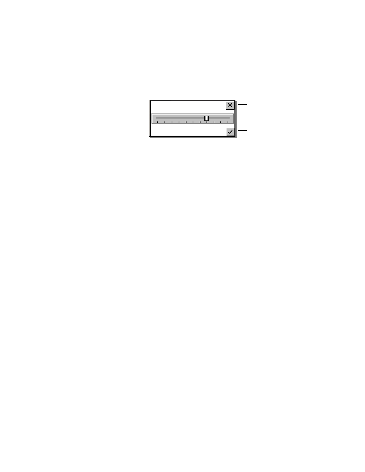
Visit the Alpha website at www.alpha.ca for the latest manual and product downloads
e
d
Once the password is verified, appropriate access level will be granted and a pop-up window will provide
acknowledgement; e.g., “Supervisor Access Granted.” If no password is entered, the user will be granted User
access. In User access mode, the user cannot make changes to parameters but may navigate through menus,
see Figure 23.
4.7.2 Contrast Adjustment of the GUI
Via the Argus icon, a pop-up window enables the user to access the contrast adjustment of the GUI. Tap
“Contrast” on the pop-up window. Figure 16 below shows the contrast adjustment window. Use the slider on the
GUI to adjust contrast as desired.
Discard changes and
Tap slider to increase or decreas
contrast of GUI as require
return to previous screen
Accept changes and
return to previous screen
Figure 16–Contrast adjustment pop-up window
4.7.3 Reset
Via the Argus icon, the user can reset the CXC. This enables the CXC to finish saving files to flash memory.
NOTE: The CXCP and CXCR models provide battery backup of time and date; the other CXC models do not.
Tap “Reset” on the pop-up window. A new pop-up window will alert the user “You are about to perform a system
reset.”
To abort the operation, tap “Cancel” or the “X” button to clear the pop-up from the active area.
To proceed, tap “Accept” and a pop-up window will notify the user “Performing Reset, please wait…” This window
will then be replaced with a window showing a timer counting down from 60 seconds and a button enabling the
user to “Reset Now.” A message will also appear in this window to notify the user “It is now safe to reset the
system.” The user may then tap the button or wait for the timer to count down and the operation will proceed
automatically to completion. The screen will go blank and the LED’s will flash as the CXC performs a short selftest before returning to Normal operating mode.
4.7.4 Language Selection
Via the Argus icon, a pop-up window enables the user to select English, French, Portuguese, Spanish or Chinese
characters for the display of text labels and messages.
Language files can be uploaded via web interface. The CXC can be set up for a maximum of three language files
(default plus two others) at one time pending availability.
Alpha Technologies Ltd. 034-136-C0 Rev B WC
Printed in Canada. © 2010 Alpha Technologies Ltd. ALPHA and CORDEX are trademarks of Alpha Technologies Ltd. All Rights Reserved. Page 25 of 122
Page 28

Refer to the back of this manual for Factory Service and Technical Support contact information
r
d
4.8 Date and Time (active area)
On the “home” page (Figure 2), below the Alarm Indication, the date and time are displayed. To change the date
(year, month, day) and time (hour, minute, second) settings, tap the active area of the screen to enter a new
window of operation, see Figure 17 below:
Discard changes and
return to previous screen
Tap arrows to increase o
decrease values as require
Date
2008 08 08
Time
09 15 20
Figure 17–Date and time setting window
NOTE: The CXCP and CXCR models provide battery backup of time and date; the other CXC models do not.
With the web interface, SNTP (Simple Network Time Protocol) may be used, see 4.10.1. This feature enables
synchronization of the CXC device time with an external source; i.e., the user’s network.
4.9 Saving Settings
Accept changes and
return to previous screen
Return to MAIN MENU navigation screen.
1. Press the OPTION button to evoke the SAVE/LOGOUT pop-up window, see 5.1.2.
2. Select SAVE to save the new settings (or select LOGOUT to clear).
A pop-up window will appear for confirmation of the selection.
Alternatively, for the web interface:
1. Click Submit Changes (upper left on web interface window).
2. Click Accept button on the Compare Settings window.
Alpha Technologies Ltd. 034-136-C0 Rev B WC
Printed in Canada. © 2010 Alpha Technologies Ltd. ALPHA and CORDEX are trademarks of Alpha Technologies Ltd. All Rights Reserved. Page 26 of 122
Page 29
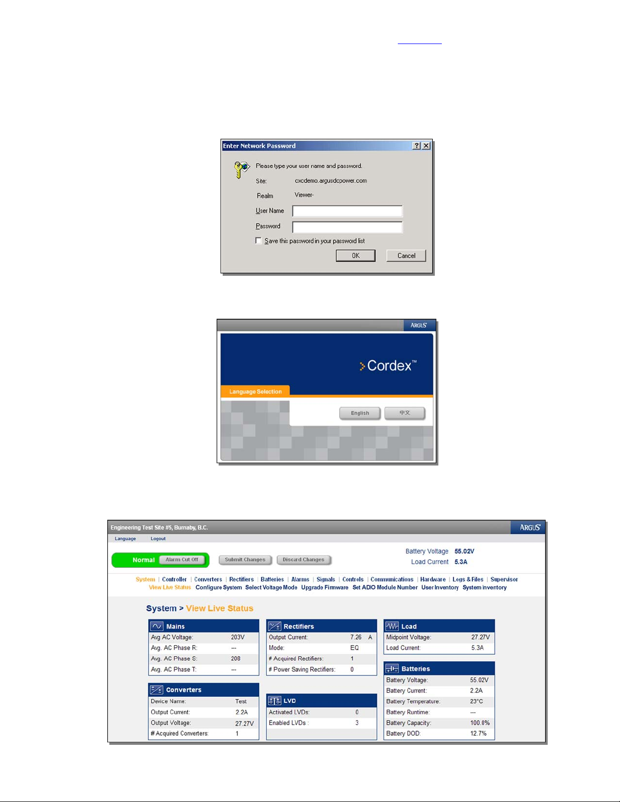
4.10 Overview of Web Interface
Refer to Chapter 9 to establish remote communications, then launch Internet Explorer 6 or greater.
Under Tools\Internet Options\Security, add the logon address of the CXC to the “Trusted Sites.”
Logon to address 10.10.10.201
Enter no USER NAME and default PASSWORD. Select OK to proceed to Language Selection window:
Visit the Alpha website at www.alpha.ca for the latest manual and product downloads
Figure 18–Enter Network Password window
Figure 19–Language Selection window
The following images show examples of windows presented when using a desktop browser to set-up or monitor
the CXC – contact Alpha for assistance as required.
Figure 20–Web Interface window (sample home page)
Alpha Technologies Ltd. 034-136-C0 Rev B WC
Printed in Canada. © 2010 Alpha Technologies Ltd. ALPHA and CORDEX are trademarks of Alpha Technologies Ltd. All Rights Reserved. Page 27 of 122
Page 30
4.10.1 SNTP (Simple Network Time Protocol)
o
e
This feature enables synchronization of the CXC device time with an external source; i.e., the user’s network.
SNTP is an adaptation or basic subset of NTP which is used for more comprehensive device time synchronization
(see www.NTP.org).
CAUTION
The CXC SNTP client will only accept responses from the external server with the ‘stratum’
parameter set in the range of 1 through 14.
With the web interface, select the Controller page and then the Date & Time window:
Toggle the check box t
Enable SNTP Servic
Refer to the back of this manual for Factory Service and Technical Support contact information
Enter target network
address for SNTP source
Figure 21–Date & Time window (Controller page)
To verify the Date/Time properties of the PC, select Start, Settings then Control Panel (Windows® 2000 operating
system). Select Date/Time and verify properties with the target network:
Select the tab for Time Zone
Use the pull-down menu to select the
correct time zone; e.g. Pacific Time
In this example, the Time Zone
Adjustment for the CXC is –8:00
Use the “-“ button in addition to the
pull-down menu to change the Time
Zone Adjustment,
then select Get Time Now to
Figure 22–Example of time zone adjustment
synchronize
Select Get Time Now to synchronize.
NOTE: SNTP service will automatically re-synchronize twenty-four hours from the time of the last synchronization.
Alpha Technologies Ltd. 034-136-C0 Rev B WC
Printed in Canada. © 2010 Alpha Technologies Ltd. ALPHA and CORDEX are trademarks of Alpha Technologies Ltd. All Rights Reserved. Page 28 of 122
Page 31

Visit the Alpha website at www.alpha.ca for the latest manual and product downloads
y
r
5 Menu Navigation and Sample Programming
5.1 Menu Navigation
The sample screen shown below (Figure 23) is presented upon login, see 4.7.1. From here, the user may
navigate (e.g. browse – as on a personal computer) each of the CXC’s menu items, including alarms, controls
and configuration items.
Mode (+Temp Comp) displa
The folders can be expanded
(indicated by the plus sign shown here)
if there are files inside.
Folders that can be collapsed will be shown
Buttons display here for additional
functions, such as programming, logout o
The “Option” button is used to logout or save changes.
The menu structure is shown in Figure 25. The next chapter describes the items that may be changed.
5.1.1 Option to Logout
Via the Option button, a pop-up window enables the user to logout of the menu navigation screen and return to
the home page.
If changes have been made, another pop-up window will prompt the user with buttons to “Save” or “Discard.” In
each case, the active area will return to the home page and a pop-up window will confirm the selection. Tapping
the “X” button will clear the pop-up from the active area.
with a minus sign.
to save changes
FL + TC
54.00V 250A
Figure 23–Menu navigation sample screen
Battery Volts and
Load Current display
Tap on the folder icon or label to expand.
Sliders and scroll bars
are used for navigation
If changes have been made, and logout is selected, another pop-up window will prompt the user with buttons to
“Save” or “Discard.”
5.1.2 Option to Save
Saving in menu navigation (Supervisor only) will result in a prompt (pop-up window) to appear; e.g., “Save
Complete” when the settings are downloaded.
If there are no changes made, then saving in menu navigation will result in a prompt (pop-up window) to appear;
e.g., “There are no changes to save.”
In each case, tapping the “X” button will clear the pop-up from the active area and remain in menu navigation. The
Supervisor will retain the security access level to continue making changes and does not return to the home page.
5.1.3 Auto-Logout Timeout
After 20 minutes of inactivity (no user input), the CXC will automatically logoff the user. The CXC will discard any
unsaved changes made by the user while logged in the system and return to Normal Operation mode. The
access level will be reset to the default user access and the screen will continue to display live data.
5.1.4 Backlight Timeout
After one minute of inactivity (no user input), the CXC will automatically turn off the LCD backlight.
Alpha Technologies Ltd. 034-136-C0 Rev B WC
Printed in Canada. © 2010 Alpha Technologies Ltd. ALPHA and CORDEX are trademarks of Alpha Technologies Ltd. All Rights Reserved. Page 29 of 122
Page 32

5.1.5 Virtual Numeric Keypad
Whenever a numeric field is selected, a virtual numeric keypad will appear (in a pop-up window) to enable editing
of the value, see Figure 24 below:
Name of value being edited
Toggle from positive to negative
Figure 24–Virtual numeric keypad pop-up window
Tap the keypad to edit or enter a value. Use the virtual function buttons described above to navigate, cancel or
accept.
5.2 Basic Programming Example
Refer to the back of this manual for Factory Service and Technical Support contact information
Cancel entry and close window
Initial value of the field
Clear entire field
Clear one number at a time
Accept entry and close window
To adjust settings in the RECTIFIERS\ CONFIGURE SETTINGS menu, see 6.3.2:
1. Using the navigation arrows, scroll to the item that is to be changed; e.g. FLOAT VOLTAGE.
2. Enter a new value using the CXC’s virtual numeric keypad (shown above); e.g. 54.00.
Download new settings to all connected rectifiers:
3. Return to MAIN MENU navigation screen and press the OPTION button to evoke the SAVE/LOGOUT pop-up
window.
4. Select SAVE to save the new settings or select LOGOUT to clear. A pop-up window will appear to confirm the
selection.
5.3 Advanced Programming
See Section 7.
When configuring Alarms (6.5.3), Signals (6.6.2), or Controls (6.7), an option to CUSTOMIZE will be presented at
the bottom of the screen. This enables the Supervisor to program separate triggering equations into the CXC
software. The equations may reference any combination (up to 16) of the analog inputs, digital inputs, virtual
inputs, and alarms utilizing logical and arithmetic arguments that simulate the functionality of a programmable
logic controller (PLC).
Alpha Technologies Ltd. 034-136-C0 Rev B WC
Printed in Canada. © 2010 Alpha Technologies Ltd. ALPHA and CORDEX are trademarks of Alpha Technologies Ltd. All Rights Reserved. Page 30 of 122
Page 33

Visit the Alpha website at www.alpha.ca for the latest manual and product downloads
Figure 25–Menu structure
Alpha Technologies Ltd. 034-136-C0 Rev B WC
Printed in Canada. © 2010 Alpha Technologies Ltd. ALPHA and CORDEX are trademarks of Alpha Technologies Ltd. All Rights Reserved. Page 31 of 122
Page 34

Refer to the back of this manual for Factory Service and Technical Support contact information
6 Menu Structure, Programming and Adjustments
The CXC menu structure (Figure 25) consists of two basic components: Menu Categories and Sub-Menu Items.
This chapter describes each of the CXC’s menu items, including alarms, controls and configuration items. They
are arranged, as they would appear in the touch screen menus subject to product enhancements.
NOTE: Items specific to the CXC web interface will be indicated separately.
6.1 System Info
This menu category consists of Factory, Site and System data. Information pertaining to the CXC, the related site
and system may be accessed here. The Supervisor can set parameters; such as, system number (Figure 28),
system serial number, and temperature display units (Figure 29).
For the web interface, this section has been divided and expanded for the associated menus/pages into
“System” and “Controller.” See Figure 20 (sample home page).
The System page still allows the Contact and System Information to be configured, the Voltage
Mode to be selected, the Firmware to be upgraded, and the ADIO Module Number to be set.
See the following sections 6.1.1 through 6.1.4.
The Controller page allows the Date & Time (4.8), and Temperature Units (6.1.6) to be set, and
the Factory Information is displayed (6.1.7). In addition, the menu links are located here to
upgrade the Bootloader and Software. A remote reset of the CXC may also be commanded via
a link on this page.
NOTE: Bootloader is the program that the CXC starts up with first and then it loads the
Cordex operating system (similar to DOS); therefore, when upgrading the Cordex
software, the bootloader should be installed after the new operating system.
6.1.1 System Configuration
This menu item enables the Supervisor to select the system voltage. Use pull-down menu to make selection.
CAUTION
This item effects all system settings that pertain to the system voltage including LVD levels.
6.1.2 CAN Device Firmware (FW) Upgrade [CX Series only]
This menu item enables the Supervisor to select, transfer and upgrade firmware for the CAN-enabled system
devices; such as, Shunt Multiplexer (MUX) or CXRC rectifier shown in the following example:
1. Select Load From Device to see a list of Acquired Devices (or select the X icon to
cancel entry and close window).
2. Select device from list. Get Firmware will produce a message window prompting to
accept (or cancel).
3. Select Accept to proceed with firmware transfer. Select the X icon (in the message
window) when transfer is complete.
4. Select Use Firmware to see a list of Upgrade Devices (or select the X icon to cancel
entry and close window).
5. Use the check box to select/deselect device from list. Perform Upgrade will produce a
message window prompting to accept (or cancel).
6. Select Accept to proceed with firmware upgrade. Rectifier LEDs will flash in
sequence to indicate data transfer. Select the X icon when upgrade is complete.
Alpha Technologies Ltd. 034-136-C0 Rev B WC
Printed in Canada. © 2010 Alpha Technologies Ltd. ALPHA and CORDEX are trademarks of Alpha Technologies Ltd. All Rights Reserved. Page 32 of 122
Page 35

Visit the Alpha website at www.alpha.ca for the latest manual and product downloads
;
2
7.
Figure 26–Firmware upgrade procedure
NOTE: Repeat the steps above choosing Shunt MUX as required.
6.1.3 Set ADIO Module Number
This menu item enables the Supervisor to select and map the order number in which CAN-enabled system
devices, such as Battery Cell Monitor (BCM), are to appear in the CXC menus; shown in the examples below:
Discard changes and
Select module for mapping
e.g. module
The module number is
important when any of the
signals from an ADIO device
is used for custom signals or
data logging.
return to previous screen
Tap arrows to
increase or decrease
value as required
Accept changes and
return to previous screen
Figure 27–ADIO Modules and Swap Modules windows
NOTE: When replacing ADIO modules, assign the new identical device with the same ADIO module number of the old
device. This is to preserve the functionality of any equations that use signals originating on the old device.
6.1.4 Site Information
6.1.4.1 System Number
This is where the power system number is displayed/edited.
6.1.4.2 System Serial
This is where the power system serial number is displayed/edited.
Figure 28–Site Information and Contact Information windows
Alpha Technologies Ltd. 034-136-C0 Rev B WC
Printed in Canada. © 2010 Alpha Technologies Ltd. ALPHA and CORDEX are trademarks of Alpha Technologies Ltd. All Rights Reserved. Page 33 of 122
Page 36

u
6.1.5 Contact Information
This menu item provides for a convenient display of the site and contact information. A scroll
bar enables the user to navigate the list of text items for viewing; i.e., Site Name, City, Region,
Country, Contact Name, Phone Number and Site Number.
6.1.6 Temperature Units
This menu item enables the Supervisor to select the temperature display units (Celsius or Fahrenheit).
Select from the pull-down men
Figure 29–Temperature Units selection window
6.1.7 Factory Information
This is where the CXC’s factory unit default values are displayed. A scroll bar enables the user to navigate the list
of text items for viewing; i.e., Unit Serial, Hardware Rev. (revision), Ethernet/MAC Address and Factory Notes.
6.1.8 User Inventory (Web Interface Only)
Refer to the back of this manual for Factory Service and Technical Support contact information
Accept change and
return to previous screen
This page enables the user to enter data for up to 20 inventory items. When entering data, the tab key may be
used to move the cursor from one data entry box to the next. See Figure 30 below:
Figure 30–User Inventory window (web interface only)
Alpha Technologies Ltd. 034-136-C0 Rev B WC
Printed in Canada. © 2010 Alpha Technologies Ltd. ALPHA and CORDEX are trademarks of Alpha Technologies Ltd. All Rights Reserved. Page 34 of 122
Page 37

6.1.9 System Inventory (Web Interface Only)
This page enables the user to view a single list of all CAN connected devices, user inventory items, and battery
information items. See Figure 31 below:
Select pull-down menu for device
details:
Figure 31–System Inventory window (web interface only)
Visit the Alpha website at www.alpha.ca for the latest manual and product downloads
6.2 Converters
This menu category consists of converter alarms and controls. Parameters can be set/accessed such as output
voltage, OVP, high/low voltage alarms, and start delay.
The converter defaults will be based on the system voltage if it is either 24 or 48Vdc.
NOTE: At present, the converter software does not support:
Two types of converters simultaneously
12, 125, and 220Vdc systems.
Other features include:
Active voltage control Inventory update
Converter locate Loadsharing
Firmware upgrade Major and minor alarms
6.2.1 Converter Report
This feature will enable the user to view, in a list report (see 4.4.2, Figure 9), all of the acquired converters in the
system. The first column lists the serial numbers of the converters. The report then displays the output current of
each converter under the Amps column (or toggle for % of maximum output) and the number of active alarms
under the Alarms column (if that converter is issuing an alarm). The rightmost column displays the number of
settings out of tolerance (OOT per web interface).
Select a converter and tap “View Details” to produce another list showing details of the entire converter alarms
and settings that are out of tolerance.
6.2.2 Configure Settings
This feature will enable the user to configure settings (via menu items) for all of the acquired converters in the
system; such as:
Output Voltage Start Delay
OVP Enable CL Alarm
Input Voltage Shutdown Input Voltage Restart
Alpha Technologies Ltd. 034-136-C0 Rev B WC
Printed in Canada. © 2010 Alpha Technologies Ltd. ALPHA and CORDEX are trademarks of Alpha Technologies Ltd. All Rights Reserved. Page 35 of 122
Page 38

6.3 Rectifiers
This menu category consists of rectifier alarms and controls. Parameters can be set/accessed such as
float/equalize voltages, high/low voltage alarms, and start delay.
6.3.1 Rectifier Report
This feature will enable the user to view, in a list report (see 4.4.2, Figure 9), all of the acquired rectifiers in the
system. The first column lists the serial numbers of the rectifiers. The report then displays the output current of
each rectifier under the Amps column (or toggle for % of maximum output) and the number of active alarms under
the Alarms column (if that rectifier is issuing an alarm). The rightmost column displays the number of settings out
of tolerance (OOT per web interface).
Select a rectifier and tap “View Details” to produce another list showing details of the entire rectifier alarms and
settings that are out of tolerance.
6.3.2 Configure Settings
This feature will enable the user to configure settings (via menu items) for all of the acquired rectifiers in the
system.
Refer to the back of this manual for Factory Service and Technical Support contact information
Discard changes and
return to previous screen
Sliders and scroll bars
are used for navigation
Select menu item to configure
Accept changes and
return to previous screen
Figure 32–Configure Settings (rectifiers) window
The menu items described below may be configured via a virtual numeric keypad (5.1.5) or by toggling the listed
item. For a basic programming example, see 5.2.
6.3.2.1 Float (FL) Voltage
This menu item enables the Supervisor to set the system BATTERY VOLTAGE (measured at
an analog input channel) to the desired float voltage value. Float voltage charges the battery
string and supplies the load. Normally, the power system will operate in the float mode. This
setting should have a minimum of LVD + 1V and a maximum of OVP – 1V.
6.3.2.2 Equalize (EQ) Voltage
This menu item enables the Supervisor to set the system BATTERY VOLTAGE (measured at
an analog input channel) to the desired equalize voltage value. Equalize voltage charges the
battery string at a higher than normal voltage to either recharge batteries after a power failure or
to balance individual cell voltages. Periodic equalizing of the battery string may be required to
optimize battery performance and life. This setting should have a minimum of LVD + 1V and a
maximum of OVP – 1V.
6.3.2.3 Battery Test (BT) Voltage
This menu item enables the Supervisor to set the Battery (Discharge) Test Voltage to the
desired value during the test (mode). This setting should have a minimum of LVD + 1V.
6.3.2.4 Safe Voltage
This menu item enables the Supervisor to set the default system voltage (Safe Mode) in the
event that communications to Cordex rectifiers should fail. See 3.4 for more details about this
feature.
Alpha Technologies Ltd. 034-136-C0 Rev B WC
Printed in Canada. © 2010 Alpha Technologies Ltd. ALPHA and CORDEX are trademarks of Alpha Technologies Ltd. All Rights Reserved. Page 36 of 122
Page 39

6.3.2.5 OVP Voltage
This menu item enables the Supervisor to program one OVP setting for all connected rectifiers.
OVP will disable a rectifier that outputs an abnormally high voltage.
6.3.2.6 Low Voltage Alarm (LVA)
This menu item enables the Supervisor to program one LVA setting for all connected rectifiers.
LVA serves as a warning to the user indicating that output voltage is dropping.
6.3.2.7 High Voltage Alarm (HVA)
This menu item enables the Supervisor to program one HVA setting for all connected rectifiers.
HVA serves as a warning to the user indicating that output voltage is rising. This value should
be less than the OVP setting in order for the HVA to work effectively.
6.3.2.8 Current Limit (CL)
This menu item sets the level as a percentage at which current limiting activates in all
connected rectifiers.
Current limiting is a primary response to output over current situations. If the output current on
the rectifiers exceeds the current limit setting, their output voltage will automatically decrease
but will maintain the current output at the current limit level. This prevents potential damage to
the rectifiers.
If the CXC finds rectifiers in the system that cannot meet the default current limit value, the CXC
will correct its default limit setting to match the rectifiers.
Visit the Alpha website at www.alpha.ca for the latest manual and product downloads
6.3.2.9 Power Limit (PL)
This menu item sets the level as a percentage at which power limiting activates in all connected
Cordex rectifiers.
6.3.2.10 EQ Timeout
This menu item controls the maximum equalize time setting for all connected rectifiers. This
control is designed to prevent accidental over-charge of the batteries. CXC will send the
command to change the equalize time-out setting in all the rectifiers.
6.3.2.11 BT Timeout
This menu item controls the duration of the Battery Test.
6.3.2.12 Slope (Pathfinder rectifiers only)
This menu item sets all connected rectifiers to the same slope adjustment value. Slope
determines the regulation percentage of the current between rectifiers in a group. When load
sharing is initialized, CXC will send commands to the rectifiers to try to adjust their output
voltage within this slope range. The rectifiers should have their output voltage as close to being
equal, in order to balance (or share) the load current between them.
6.3.2.13 Backlight Timeout (Pathfinder rectifiers w/LCD only)
This menu item controls the amount of time of GUI inactivity permitted before the rectifier
automatically turns off the LCD backlight.
6.3.2.14 Security Code (Pathfinder rectifiers w/LCD only)
This menu item enables the Supervisor to program one security access code for all connected
rectifiers. CXC logs in each of the rectifiers as Factory Access and sends the direct command to
change the access code.
Alpha Technologies Ltd. 034-136-C0 Rev B WC
Printed in Canada. © 2010 Alpha Technologies Ltd. ALPHA and CORDEX are trademarks of Alpha Technologies Ltd. All Rights Reserved. Page 37 of 122
Page 40

Refer to the back of this manual for Factory Service and Technical Support contact information
6.3.2.15 Module Start Delay
This menu item controls the stagger-start timer for all connected rectifiers.
With start delay, rectifiers start up in a time-delayed sequence. This prevents excessive loading
of the AC source. For example, setting a start delay time of 5 seconds will cause rectifier#1 to
start at 1 second, rectifier#2 at 5 seconds, rectifier#3 at 10 seconds, etc. In the case where the
start delay exceeds the maximum range, the next rectifier in sequence will start its delay at zero
and increment again by the value specified in this menu item.
When the rectifier Module Start Delay is set to 0 s, all the rectifiers start with a 0 s delay.
6.3.2.16 System Start Delay
This menu item controls the amount of time, in seconds, before the stagger-start timer
commences, see 6.3.2.15 above.
6.3.2.17 Soft Start Ramp Rate (Cordex rectifiers only)
This menu item enables the Supervisor to select the soft start ramp rate (normal or fast).
Current limit ramps up at about 12%/s during normal soft start and 33%/s during fast.
For systems without batteries, select the Fast setting for the Soft Start Ramp Rate.
6.3.2.18 Temp Display Scale (Pathfinder rectifiers w/LCD only)
This menu item enables the Supervisor to select the temperature display scale (Celsius or
Fahrenheit).
6.3.2.19 Check to Enable
This menu item enables the Supervisor to toggle (enable or disable) the following list of items:
6.3.3 Power Save
This feature will enable the Supervisor to improve operational efficiency when conditions warrant by running only
the necessary number of rectifiers. The remote shutdown setting (enable or disable) affects correct operation of
the Power Save feature. See also 3.5 for more details.
6.3.3.1 Enable
This menu item enables the Supervisor to control the CXC’s Power Save feature.
6.3.3.2 Redundant Rectifiers
This menu item enables the Supervisor to specify the number of extra rectifiers to turn on.
6.3.3.3 Max (Maximum) Power Usage
This menu item enables the Supervisor to specify the percentage (of maximum power usage)
per rectifier module used in the computation of the Power Save feature. This works to avoid
rectifiers operating continuously at greater than the set limit (i.e. 95%) and going into current
limit frequently due to load surges or power limit conditions; such as, low line voltage or high
temperature.
CL and PL Alarm
Remote Shutdown (Cordex rectifiers only; affects operation of Power Save, see below)
Local Access Alarm (Pathfinder rectifiers w/LCD only)
Ramp Test (Cordex rectifiers only)
Alpha Technologies Ltd. 034-136-C0 Rev B WC
Printed in Canada. © 2010 Alpha Technologies Ltd. ALPHA and CORDEX are trademarks of Alpha Technologies Ltd. All Rights Reserved. Page 38 of 122
Page 41

6.3.4 Phase Mapping
e
)
l
d
o
n
This feature will enable the user to assign or map a rectifier per input signal for individual phase voltage readings:
Assign/map a rectifier per Phas
R, S, and T (radio buttons
for the respective signa
Tap Locate and the LEDs of the selecte
rectifier will flash to enable the user t
determine the phase connectio
6.4 Batteries
This menu category consists of battery controls. Parameters can be set/accessed, such as automatic temperature
compensation, auto equalize and battery current (I) limit.
See Standard Features chapter for an explanation of temperature compensation and lead acid battery
auto equalization.
Visit the Alpha website at www.alpha.ca for the latest manual and product downloads
Discard changes and
return to previous screen
Accept changes and
return to previous screen
Figure 33–Phase Mapping (rectifiers) window
6.4.1 Temperature Compensation (Temp Comp)
6.4.1.1 Enable
This menu item enables the Supervisor to control the CXC’s temperature compensation feature.
Automatic battery temperature compensation may be enabled in equalize mode independently
from float mode. Battery Properties section must be completed to enable this feature.
6.4.1.2 Upper/Lower Breakpoints
This menu item enables the Supervisor to program the temperature at which automatic voltage
changes in the system will cease. There are voltage and temperature values for both
breakpoints (upper and lower).
6.4.1.3 Battery Properties (See 6.4.8)
The “Battery Properties” button at the bottom of the Temp Comp window is a link to the Battery
Properties window.
The return path (the menu structure) will remain intact; i.e., the user will return through the
window where the Battery Properties button was tapped.
6.4.2 Auto Equalize
6.4.2.1 EQ Duration
This menu item enables the Supervisor to program the duration of the auto equalize cycle, in
hours.
The duration setting is also used in manual equalize mode. Consult the battery manufacturer for
suggested duration of equalize charge cycles.
Alpha Technologies Ltd. 034-136-C0 Rev B WC
Printed in Canada. © 2010 Alpha Technologies Ltd. ALPHA and CORDEX are trademarks of Alpha Technologies Ltd. All Rights Reserved. Page 39 of 122
Page 42

6.4.2.2 Periodic Auto-EQ
Enable
This menu item enables the Supervisor to control the CXC’s periodic auto equalize feature.
Interval
This menu item enables the Supervisor to program the time between auto equalize charging of
the battery string in days. Consult the battery manufacturer for suggested equalize charge-time
interval.
6.4.2.3 Charge Auto-EQ
Enable
This menu item enables the Supervisor to control the CXC’s Charge Auto Equalize feature.
Activation (High Voltage) Threshold
This menu item enables the Supervisor to program the voltage at which the auto equalize
charging will activate.
Arming (Low Voltage) Threshold
This menu item enables the Supervisor to program the voltage at which the auto equalize
charging will arm.
6.4.2.4 Battery Properties (See 6.4.8)
The “Battery Properties” button at the bottom of the Auto Equalize window is a link to the
Battery Properties window.
Refer to the back of this manual for Factory Service and Technical Support contact information
The return path (the menu structure) will remain intact; i.e., the user will return through the
window where the Battery Properties button was tapped.
Alpha Technologies Ltd. 034-136-C0 Rev B WC
Printed in Canada. © 2010 Alpha Technologies Ltd. ALPHA and CORDEX are trademarks of Alpha Technologies Ltd. All Rights Reserved. Page 40 of 122
Page 43

6.4.3 Charge Current Control (CCC)
6.4.3.1 Enable
This menu item enables the Supervisor to control the CXC’s Charge Current Control feature.
Battery Properties section must be completed to enable this feature.
6.4.3.2 Charge Rate Limit
This menu item enables the Supervisor to program the amount of current that goes into the
battery and is dependent upon the Supervisor-entered parameter Capacity Rating (C), see
6.4.8.1. The Charge Rate amount is represented in amps (X) or as a C/X value (Capacity
Rating/Charge Rate Amps).
The Charge Rate Amps is recalculated if the Charge Rate C/X value or the Capacity Rating is
modified.
Visit the Alpha website at www.alpha.ca for the latest manual and product downloads
Figure 34–Charge Current Control web interface window
6.4.3.3 Enable Dynamic CCC
This menu item enables the Supervisor to control the CXC’s Dynamic Charge Current Control
feature. Battery Properties section must be completed to enable this feature.
NOTE: There is a separate set of Charge Rate Limit values that can be input for the
Dynamic CCC feature.
6.4.3.4 Battery Properties (See 6.4.8)
The “Battery Properties” button at the bottom of the Charge Current Control window is a link to
the Battery Properties window.
The return path (the menu structure) will remain intact; i.e., the user will return through the
window where the Battery Properties button was tapped.
Dynamic CCC Trigger
This pull-down menu enables the Supervisor to
select the event that triggers the Dynamic CCC
feature (if enabled).
Alpha Technologies Ltd. 034-136-C0 Rev B WC
Printed in Canada. © 2010 Alpha Technologies Ltd. ALPHA and CORDEX are trademarks of Alpha Technologies Ltd. All Rights Reserved. Page 41 of 122
Page 44

6.4.4 Battery Monitor
6.4.4.1 Enable
This menu item enables the Supervisor to control the CXC’s battery monitor feature.
Battery Properties section must be completed to enable this feature.
6.4.4.2 Load Type
This menu item enables the Supervisor to select the type of load on the system: constant
power, current, or resistive. This is used for battery capacity calculations.
6.4.4.3 Disconnect Voltage
The disconnect voltage should be set to the value of the LVD that will disconnect the battery
from the load. The Battery Runtime algorithm uses this value to calculate the hours remaining
during an AC outage.
6.4.4.4 Reset Battery Monitor
The Battery Monitor should be reset when installing new or different batteries.
6.4.4.5 Battery Properties (See 6.4.8)
The “Battery Properties” button at the bottom of the Battery Monitor window is a link to the
Battery Properties window.
The return path (the menu structure) will remain intact; i.e., the user will return through the
window where the Battery Properties button was tapped.
Refer to the back of this manual for Factory Service and Technical Support contact information
6.4.5 Battery (Discharge) Test
The Battery Test (BT) is used to update the status of the battery capacity. It can be set to run automatically or can
be initiated manually (via Mode Selection button). See 4.3.4 for more details.
6.4.5.1 BT End Voltage
This menu item controls the end (or termination) voltage of the BT; +0.5V above Rectifier BT
Voltage is recommended.
Rectifier BT Voltage (identical to 6.3.2.3 – a change in one alters the other)
This menu item enables the Supervisor to set the Rectifier BT Voltage to the desired value
during the test (mode). This setting should have a minimum of LVD + 1V.
Rectifier BT Timeout (identical to 6.3.2.11 – a change in one alters the other)
This menu item controls the duration of the Battery Test.
6.4.5.2 Auto-BT
Enable
This menu item enables the Supervisor to control the CXC’s Auto-BT feature.
Interval
This menu item enables the Supervisor to program the time, in days, between Auto Battery
Tests.
Alpha Technologies Ltd. 034-136-C0 Rev B WC
Printed in Canada. © 2010 Alpha Technologies Ltd. ALPHA and CORDEX are trademarks of Alpha Technologies Ltd. All Rights Reserved. Page 42 of 122
Page 45

6.4.5.3 Remote BT Mode
This feature will force a transition to BT mode when a user-defined condition (custom alarm) is
true.
Enable
This menu item enables the Supervisor to control the CXC’s Remote BT feature.
Remote BT (Custom 1-20)
This menu item enables the Supervisor to assign the Custom Alarm (see 6.5.3 Configure
Alarms) number between 1 and 20.
NOTE: This feature is exclusive for the Cordex series of rectifiers. If Remote BT is
active and a rectifier other than the Cordex series is added to the system then
Remote BT will be aborted.
6.4.5.4 Battery Properties (See 6.4.8)
The “Battery Properties” button at the bottom of the Battery Test window is a link to the Battery
Properties window.
The return path (the menu structure) will remain intact; i.e., the user will return through the
window where the Battery Properties button was tapped.
6.4.6 Battery Current Termination (BCT) Equalize
Refer to Section 3.7.3 for feature overview.
Visit the Alpha website at www.alpha.ca for the latest manual and product downloads
Since the BC Threshold is in amps, it has to be set with caution since the battery current input has limited
accuracy. If it is too low, the threshold may never be reached. The threshold should be at least twice as large as
the jitter on the battery current input. If this limitation forces the threshold to be set higher than desired, the BCT
Duration can be increased slightly to compensate.
6.4.6.1 Enable
This menu item enables the Supervisor to control the CXC’s BCT Equalize feature.
6.4.6.2 Duration
This menu item enables the Supervisor to program the duration of the BCT Equalize in hours.
6.4.6.3 BC Threshold
This menu item enables the Supervisor to program the threshold (in amps) for the battery
charging current that will trigger the BCT Equalize.
6.4.6.4 Battery Properties (See 6.4.8)
The “Battery Properties” button at the bottom of the BCT Equalize window is a link to the Battery
Properties window.
The return path (the menu structure) will remain intact; i.e., the user will return through the
window where the Battery Properties button was tapped.
Alpha Technologies Ltd. 034-136-C0 Rev B WC
Printed in Canada. © 2010 Alpha Technologies Ltd. ALPHA and CORDEX are trademarks of Alpha Technologies Ltd. All Rights Reserved. Page 43 of 122
Page 46

Refer to the back of this manual for Factory Service and Technical Support contact information
6.4.7 Boost (BST) Mode
This feature will allow a transition to BST mode when a user-defined condition (custom alarm) is false.
NOTE: Activation is manual and certain conditions must be met to prevent damage to the load.
A custom alarm must be created to include all the desired factors that must be taken into account before
activating BST mode. This mode will then only be permitted if the alarm is false.
Once activated, BST mode concludes with a timeout or whenever the status of the custom alarm is true and
reverts to FL mode. BST mode can also be cancelled if the conditions that are required in order to activate BST
mode have changed.
6.4.7.1 Enable
This menu item enables the Supervisor to control the CXC’s Boost Mode feature.
6.4.7.2 Voltage
This menu item controls the deviation of the Boost Mode voltage.
6.4.7.3 Timeout
This menu item controls the duration of the Boost Mode.
6.4.7.4 Inhibit
This menu item enables the Supervisor to assign the Custom Alarm (see 6.5.3 Configure
Alarms) number between 1 and 20.
6.4.7.5 Battery Properties (See 6.4.8)
The “Battery Properties” button at the bottom of the Boost Mode window is a link to the Battery
Properties window.
The return path (the menu structure) will remain intact; i.e., the user will return through the
window where the Battery Properties button was tapped.
6.4.8 Battery Properties
Battery Properties contain information that is provided by the battery manufacturer. This data is used by Charge
Current Control, Battery Monitor, and Temperature Compensation.
6.4.8.1 Capacity Rating (20-Hour Rate)
This menu item will enable the Supervisor to set the specified total capacity of the battery string
(derived from battery manufacturer’s specifications and should correspond to the C/20 Capacity
if possible). This value will be used in the calculations for charge current control function and
capacity estimation.
NOTE: If multiple strings are used, this value will represent the total combined capacity
of all battery strings summed together.
6.4.8.2 Capacity Calibration
Selecting this Item will enable the Supervisor to enter a value to effectively “calibrate” the
Battery Capacity. This is necessary when the batteries are first commissioned and whenever an
independent test is done to measure the battery’s capacity.
6.4.8.3 Open Circuit Voltage
This menu item will enable the Supervisor to set the open circuit voltage (derived from battery
manufacturer’s specifications).
Alpha Technologies Ltd. 034-136-C0 Rev B WC
Printed in Canada. © 2010 Alpha Technologies Ltd. ALPHA and CORDEX are trademarks of Alpha Technologies Ltd. All Rights Reserved. Page 44 of 122
Page 47

Visit the Alpha website at www.alpha.ca for the latest manual and product downloads
6.4.8.4 Peukert Number
This number can be entered in two ways. If the Supervisor has a Peukert number from the
battery manufacturer, then it can be entered as a simple, one step numeric entry.
NOTE: The Peukert number relates to the internal resistance of a battery and provides an
indication (inversely) of the expected capacity; that is, a lower number is better.
If the Supervisor does not have a Peukert number, it must be calculated. This multi-step
process involves entering four numbers derived from battery manufacturer’s specifications.
Resulting Peukert number should be above 1.000 and below 2.000.
Figure 35–Battery Properties and Peukert Calculator windows
Peukert Calculator
To calculate the Peukert number the Supervisor must enter unique values for Peukert Time 1
and Peukert Time 2 and the corresponding discharge current for each. This information is taken
from the battery specification sheet. Typically, time values of two hours and twenty hours
provide the necessary data for the Peukert number calculation.
6.4.8.5 Temp Comp Slope
This menu item enables the Supervisor to enter the desired temperature compensation slope.
6.4.8.6 Number of Cells
This menu item enables the Supervisor to enter the number of battery cells per string.
6.4.9 Battery Information
The web interface provides an additional window to enter/view the manufacturer’s data for the batteries in the
system; e.g., for inventory purposes. When entering data, the tab key may be used to move the cursor from one
data entry box to the next data entry box. See Figure 36 below.
NOTE: This information is separate from the battery properties (see previous section) used for the existing battery
management features of the CXC. The data must be obtained from the battery supplier and entered by the CXC
Supervisor.
Figure 36–Battery Information web interface window
Alpha Technologies Ltd. 034-136-C0 Rev B WC
Printed in Canada. © 2010 Alpha Technologies Ltd. ALPHA and CORDEX are trademarks of Alpha Technologies Ltd. All Rights Reserved. Page 45 of 122
Page 48

6.5 Alarms
This menu category consists of power system alarms. Parameters can be set/accessed such as power system
high/low voltage alarms, AC Mains high/low voltage alarms, Supervisor programmable alarms and alarm tone
enable (audible alarm buzzer).
All voltage-related alarms (HVA 1 and 2, LVA 1 and 2) are based on voltage readings taken from analog input
channel for the power system’s BATTERY VOLTAGE.
See Table I for factory default settings.
6.5.1 Definitions
Major — This alarm consists of a group of alarm conditions that are considered serious or an immediate threat to
service. The red front panel LED illuminates and the Major Alarm icon displays on the GUI.
Minor — This alarm consists of alarm conditions that are considered to be of a less serious nature or not an
immediate threat to service. The yellow front panel LED illuminates and the Minor Alarm icon displays on the GUI.
Message — This is a non-audible non-priority alert. There is no change of LED activity and the Message icon
displays on the GUI. The Supervisor may define the condition(s) and set relays to change.
Rectifier Major Fail Count — This alarm is the count of the number of rectifiers that are in a fail condition
resulting in a major alarm or an immediate threat to service. The setting can be adjusted in the RECTIFIER
MAJOR FAIL COUNT submenu.
Rectifier Minor Fail Count — This alarm is the count of the number of rectifiers that are in a fail condition
resulting in a minor alarm or non-immediate threat to service. The setting can be adjusted in the RECTIFIER
MINOR FAIL COUNT submenu.
Refer to the back of this manual for Factory Service and Technical Support contact information
Rectifier Minor Alarm — This is an alarm condition detected in a rectifier but is not considered an immediate
threat to the operation of that rectifier.
Rectifier Fail Alarm — This is an alarm condition detecting a true or actual rectifier failure.
ALCO — Alarm cutoff (see Cutoff All Alarms button on page 23) will silence all ALCO enabled alarms as well as
change relay state. For controls, the relay does not change state – only the audible alert is silenced.
6.5.2 Alarm Icons
The following icons display on the GUI to indicate condition and priority:
— An active alarm condition.
— An alarm condition that has been silenced.
— A power system Major Alarm.
— A power system Minor Alarm.
— A power system Message alert.
— Rectifier Information accompanied by the number of rectifiers in the system.
— Power Save feature enabled and active accompanied by the number of rectifiers shut down.
Alpha Technologies Ltd. 034-136-C0 Rev B WC
Printed in Canada. © 2010 Alpha Technologies Ltd. ALPHA and CORDEX are trademarks of Alpha Technologies Ltd. All Rights Reserved. Page 46 of 122
Page 49

6.5.3 Configure Alarms
t
m
y
Under this window of operation, there is a pull-down menu of the following headings:
associated menu items
ADIO and Converter Alarms
Select heading to list
This list can include:
Visit the Alpha website at www.alpha.ca for the latest manual and product downloads
Pull-down menu for alarm headings
Sliders and scroll bars
are used for navigation
Select menu item to configure
Tap Configure to edi
selected menu ite
Accept changes and
return to previous screen
Figure 37–Configure Alarms window showing headings
For each of these headings there is a list of menu items with a scroll bar for navigation. Tap to select.
Tap “Configure” to enter a new window of operation for the item selected. In this new window, the Supervisor can
set the following parameters:
Name of item being edited
Toggle the check box to select
Supervisor may toggle the check box to
select e-mail notification. See 10.3.3.
When selecting SNMP, the severit
level (numeric) may also be set.
Discard changes and
return to previous screen
Select from the pull-down menus:
Relay Mapping – N/A or relay 1 through 16.
Priority – Major, Minor or Message.
Accept changes and
return to previous screen
Figure 38–Configure (item selected) sample window
Alarms cannot be mapped to a relay unless it is enabled. Disabling an alarm that is mapped to a relay will free up
that relay.
Occupied relays are indicated by the tilde “~” character beside the relay number.
Some parameters are factory set and will not be displayed under the Configure window for all alarms. Here are
some of the additional parameters the Supervisor can expect to encounter:
Activation — Select from the pull-down menu; e.g., High or Low.
Activation Value — Tap on the number to edit via a virtual numeric keypad.
Equation — Tap Customize to edit (via Custom Alarms window).
Source — Select from the pull-down menu; e.g., Dig1 through Dig8.
Alpha Technologies Ltd. 034-136-C0 Rev B WC
Printed in Canada. © 2010 Alpha Technologies Ltd. ALPHA and CORDEX are trademarks of Alpha Technologies Ltd. All Rights Reserved. Page 47 of 122
Page 50

Refer to the back of this manual for Factory Service and Technical Support contact information
The web interface provides a list of all alarms in one place. The configuration of most alarms may be done on this
one screen:
The Alarms that have an
extra (advanced) setting
will appear as a link.
Click on the link to open a
new window for editing
the advanced setting.
Supervisor may toggle the
check box to select e-mail
notification. See 10.3.3.
When selecting SNMP, the
severity level (numeric) may
also be set.
Figure 39–Configure Alarms sample web interface window
6.5.3.1 Overview of Output Relay Channels and Configuration
One active control can be mapped for each of the relays; for example, Relay 1 can be
unassigned from LVD 1 then remapped as an alarm relay.
Any alarm (even multiple alarms) can be mapped to any unoccupied relay.
The table below summarizes the output channel assignments:
Channel Description Factory Default Designation
Relay 1 LVD 1
Relay 2 LVD 2
Relay 3 LVD 3
Relay 4 POWER SYSTEM MINOR ALARM
Relay 5 POWER SYSTEM MAJOR ALARM
Relay 6 AC MAINS HIGH/LOW ALARM
Relay 7 RELAY 7 (Unassigned)
Relay 8 RELAY 8 (Unassigned)
Relay 9 – 16 …(Unassigned)
Table A–Output channel assignments
Alpha Technologies Ltd. 034-136-C0 Rev B WC
Printed in Canada. © 2010 Alpha Technologies Ltd. ALPHA and CORDEX are trademarks of Alpha Technologies Ltd. All Rights Reserved. Page 48 of 122
Page 51

The following sections describe the menu headings and the associated lists of items.
6.5.3.2 Rectifier Alarms
Rectifier Fail
This menu item enables the Supervisor to set an alarm condition for a true or actual rectifier
failure. The activation value is factory set.
Rectifier Minor
This menu item enables the Supervisor to set an alarm condition for a minor rectifier failure; i.e.,
an alarm condition detected in a rectifier, but one that is not considered an immediate threat to
the operation of that rectifier. The activation value is factory set.
Rect. Major Fail Count
This menu item enables the Supervisor to set the total number of rectifier fail alarms that will
trigger the CXC’s rectifier major alarm. The activation value must be greater than or equal to the
total number entered for the minor rectifier fail count alarm.
Rect. Minor Fail Count
This menu item enables the Supervisor to set the total number of rectifier fail alarms that will
trigger the CXC’s rectifier minor alarm. The activation value must be less than or equal to the
number entered for the major rectifier fail count alarm.
Rectifier Lockout (Pathfinder series only)
This menu item enables the Supervisor to set an alarm condition when a Pathfinder series
rectifier lockout is detected. The activation value is factory set.
Visit the Alpha website at www.alpha.ca for the latest manual and product downloads
Out of Tolerance
This menu item enables the Supervisor to set an alarm condition when a rectifier out of
tolerance is detected. The activation value is factory set.
Rect. Comms Lost
This menu item enables the Supervisor to set an alarm condition when rectifier communications
is lost. The activation value is factory set.
Rect. Equalize Activated
This menu item enables the Supervisor to set an alarm condition when a rectifier in EQ mode is
detected. The activation value is factory set.
Rect. AC Mains Fail
This menu item enables the Supervisor to set an alarm condition when a rectifier AC mains fail
is detected. The activation value is factory set.
The activation value for AC Mains Fail detection is determined to be when the number of
rectifiers in AC Fail divided by the number of rectifiers acquired is greater than or equal to 90%.
Max Rectifiers Exceeded
This menu item enables the Supervisor to set an alarm condition when the maximum number of
rectifiers is exceeded. The activation value is factory set.
Fan Fail Alarm (for Fan Cooled Systems)
The purpose of this feature is to enable the CXC to trigger the alarm when a fan fail (speed
error or failed fan) condition has occurred in any of the rectifiers in the system.
The Fan Fail Alarm is true when the CXC receives a Fan Fail or Fan Speed Error alarm from any
rectifier.
The Fan Fail Alarm is cleared when all Fan Fail and Fan Speed Error alarms are cleared from all
the rectifiers.
Each time that the Fan Fail Alarm goes on/off, the “event” is logged in the Event History. Since it
is a rectifier alarm, up to nine rectifiers (up to 27 fan fail alarms) that are in alarm will be logged.
If more than nine rectifiers are in alarm an additional entry will be made indicating the total
number of rectifiers in alarm.
The activation value is factory set.
Power Save
This menu item enables the Supervisor to set an alarm condition when a rectifier is in Power
Save mode. The activation value is factory set.
Alpha Technologies Ltd. 034-136-C0 Rev B WC
Printed in Canada. © 2010 Alpha Technologies Ltd. ALPHA and CORDEX are trademarks of Alpha Technologies Ltd. All Rights Reserved. Page 49 of 122
Page 52

Refer to the back of this manual for Factory Service and Technical Support contact information
t
d
y
Urgent AC Mains Fail
This menu item enables the Supervisor to set a major alarm condition when the Rectifier AC
Mains Fail alarm has been active for a period of time; the default activation value is ten (10)
minutes:
Discard changes and
Tap on the Activation Value to edi
via a virtual numeric keypa
Toggle the check box to select
Supervisor may toggle the check box to
select e-mail notification. See 10.3.3.
return to previous screen
Select from the pull-down menus:
Relay Mapping – N/A or relay 1 through 16.
Priority – Major, Minor or Message.
When selecting SNMP, the severit
level (numeric) may also be set.
Accept changes and
return to previous screen
Figure 40–Configure Urgent AC Mains Fail sample window
6.5.3.3 Digital Alarms
This menu item enables the Supervisor to configure the alarms associated with each digital
input.
Each digital input channel is designed to detect zero-system voltage (i.e. off/on) signal. Six of
the digital channels have assigned functions, while two are unassigned. The Table below
summarizes the digital channel assignments:
Channel Description Factory Default Designation
DIG1 (D1 on PCB) Distribution Fuse/Circuit Breaker
DIG2 (D2 on PCB) Battery Fuse/Circuit Breaker
DIG3 (D3 on PCB) LVD Manual In
DIG4 (D4 on PCB) LVD Manual Out
DIG5 (D5 on PCB) Converter Fail
DIG6 (D6 on PCB) Converter I/P Breaker Trip
DIG7 (D7 on PCB) Digital 7 (unassigned)
DIG8 (D8 on PCB) Digital 8 (unassigned)
Table B–Digital input channel assignments
Digital events occurring on one of the digital inputs can be programmed to the output alarm
relays using the programming feature for the relay contact similar to analog alarms.
User (or Supervisor) may view status of each digital input under the Signals menu, see 6.6.2.3.
Alpha Technologies Ltd. 034-136-C0 Rev B WC
Printed in Canada. © 2010 Alpha Technologies Ltd. ALPHA and CORDEX are trademarks of Alpha Technologies Ltd. All Rights Reserved. Page 50 of 122
Page 53

Visit the Alpha website at www.alpha.ca for the latest manual and product downloads
The following menu items enable the Supervisor to configure the alarms associated with each analog input.
6.5.3.4 Current Alarms
Battery Current High
This menu item enables the Supervisor to program the setting for the battery amps alarm. When
the total current to the battery exceeds this setting, the alarm is activated and the message
BATTERY CURRENT HIGH is displayed on the GUI.
Load Current High
This menu item enables the Supervisor to program the setting for the load amps alarm. When
the current to the load has exceeded this setting, an alarm is activated and the message LOAD
CURRENT HIGH is displayed on the GUI.
6.5.3.5 Voltage Alarms
AC Mains High
This menu item enables the Supervisor to program the setting for the mains high alarm. When
the AC exceeds this setting, the alarm is activated and the message AC MAINS HIGH is
displayed on the GUI.
AC Mains Low
This menu item enables the Supervisor to program the setting for the mains low alarm. When
the AC input to the power system falls below this setting, the alarm is activated and the
message AC MAINS LOW is displayed on the GUI.
High Voltage [1-2]
When the power system’s DC voltage exceeds the Supervisor-specified value, the alarm is
activated and the message HIGH VOLTAGE 1 (or 2) is displayed on the GUI.
Low Voltage [1-2]
When the power system’s DC voltage falls below the Supervisor-specified value, the alarm is
activated and the message LOW VOLTAGE 1 (or 2) is displayed on the GUI.
Midpoint Monitor [1-5]
This menu item enables the Supervisor to program the setting for the midpoint monitor voltage
alarm. When the voltage reading (1 through 5) exceeds this setting (from the midpoint), the
alarm is activated and the message MIDPOINT MONITOR 1 (or 2-5) is displayed on the GUI.
6.5.3.6 Battery Alarms
Battery Runtime Low
This menu items enables the Supervisor to specify in hours when the battery runtime alarm will
activate with respect to the hours remaining in the battery runtime prediction.
Battery Capacity (Remaining) Low
This menu item enables the Supervisor to set the battery capacity alarm trigger point as a
percentage. When the capacity of the battery is depleted to this specified value, the capacity
alarm is activated.
Battery Overtemp
This menu item enables the Supervisor to set the temperature at which the battery over
temperature alarm will activate.
Battery On Discharge
This menu item enables the Supervisor to set an alarm when the battery is on discharge;
e.g., during AC Fail or BT mode.
Battery Test
This menu item enables the Supervisor to set an alarm when the Battery Test is in progress.
Boost Mode
This menu item enables the Supervisor to set an alarm when the BST mode is activated. See 0.
6.5.3.7 Temperature Alarms
Temp Sensor Fail [1-4]
This menu item enables the Supervisor to set an alarm when any temperature sensor fails.
Alpha Technologies Ltd. 034-136-C0 Rev B WC
Printed in Canada. © 2010 Alpha Technologies Ltd. ALPHA and CORDEX are trademarks of Alpha Technologies Ltd. All Rights Reserved. Page 51 of 122
Page 54

TC Sensor Fail
t
m
This menu item enables the Supervisor to set an alarm when a sensor enabled for Temp Comp
fails.
6.5.3.8 Miscellaneous Alarms
Select heading to list
associated menu items
Refer to the back of this manual for Factory Service and Technical Support contact information
Select menu item to configure
Tap Configure to edi
selected menu ite
Accept changes and
return to previous screen
Figure 41–Miscellaneous Alarms window showing menu items
Real Time Clock Error
This menu item enables the Supervisor to set an alarm when any change to the CXC’s clock
occurs; due to a battery failure or the real time clock itself failing. The alarm will become active
whenever the date is before Jan. 1, 2000 or after Dec. 31, 2030.
Invalid Device Firmware
This menu item enables the Supervisor to set an alarm in the event that the firmware of a
device (e.g. Cordex rectifier) has become corrupt and is no longer functioning.
Ground Fault Detected (High Voltage CXC only)
This menu item enables the Supervisor to set the value at which the ground fault detected alarm
will activate. The default value is +/-5mA.
Improper Controller Shutdown
This menu item enables the Supervisor to set an alarm in the event that the firmware of the
controller has become corrupt and is no longer functioning.
Invalid Battery Voltage
This menu item enables the Supervisor to set an alarm when the charging voltage is invalid;
e.g., in the event that the sense leads have become disconnected. The alarm activates when
the charge volts signal drops below 5V and halts all control of the system that relies on this
signal. If activated (enabled) an entry will be made in the event log.
System Major
This menu item enables the Supervisor to map a relay to the power system major alarm, which
is activated if there are one or more active MAJOR alarms. A pull-down menu with scroll bars
may be used for navigation.
System Minor
This menu item enables the Supervisor to map a relay to the power system minor alarm, which
is activated if there are one or more active MINOR alarms. A pull-down menu with scroll bars
may be used for navigation.
6.5.3.9 ADIO Alarms
This menu item enables the Supervisor to configure the alarms associated with each ADIO
device. Events occurring on one of the inputs can be programmed to the output alarm relays
using the programming feature for the relay contacts similar to other alarms.
User (or Supervisor) may view the device status under the ADIO Alarms Detail menu, see 6.5.4.
6.5.3.10 Custom Alarms (1-20)
This menu item enables the Supervisor to program 20 separate alarm-triggering equations into
the CXC software. The equations may reference any combination (up to 16) of the analog
inputs, digital inputs, virtual inputs, and alarms (such as Fan Fail) utilizing logical and arithmetic
arguments that simulate the functionality of a programmable logic controller (PLC). See also 7.2
Equation Builder Keypads.
Alpha Technologies Ltd. 034-136-C0 Rev B WC
Printed in Canada. © 2010 Alpha Technologies Ltd. ALPHA and CORDEX are trademarks of Alpha Technologies Ltd. All Rights Reserved. Page 52 of 122
Page 55

Visit the Alpha website at www.alpha.ca for the latest manual and product downloads
s
s
(
l
)
w
Signal and a Numeric Value Selected
In this example, one signal (V1) and a numeric value (53.50) are selected for the Custom1
alarm to be triggered when [V1] > 53.50. The first operand chosen (top pull-down menu) is
Analog Inputs. The next pull-down menu shows that the Supervisor must select from a list of
inputs of that type. An operator is selected from the virtual keypad. The keypad is then changed
to numeric in order to enter a numeric value to complete the equation.
Name of item being edited
Equation displays here
Use slider to navigate/vie
as required
Whenever CUSTOMIZE i
selected, a keypad enable
editing of the equation.
similar to the virtua
numeric keypad
Discard changes and
return to previous screen
Sliders and scroll bars
are used for navigation
Accept changes and
return to previous screen
Figure 42–Custom Alarm screen
Select Customize to program an alarm-triggering equation as described below.
At any time, as required, select the X icon to cancel entry and close window.
1. Inside the first window shown, after Customize is selected, is the equation building area,
numeric keypad and other function keys. Select [Op] for operand (pull-down menu of alarms,
signals, etc.).
2. Use pull-down menus to locate Analog Inputs: V1.
3. Select signal (e.g. V1) to add to equation builder.
4. Select Sym for arithmetic symbols (e.g. >) and logic operators and continue to build
equation.
5. Select 123 to return to numeric keypad. Enter value (e.g. 53.50) to complete equation.
6. When equation is complete, select the check mark icon (in the lower right corner) to accept
changes and return to previous window.
These notes correspond to the numbers in the sequence of figures below:
Figure 43–Customize Alarm example
Equations (from actual customer configurations)
Alpha Technologies Ltd. 034-136-C0 Rev B WC
Printed in Canada. © 2010 Alpha Technologies Ltd. ALPHA and CORDEX are trademarks of Alpha Technologies Ltd. All Rights Reserved. Page 53 of 122
Page 56

Refer to the back of this manual for Factory Service and Technical Support contact information
Example 1: Add More Rectifiers Alarm
The function of the following equation is to activate a custom alarm when load increases to a
point where redundancy is compromised, but before any rectifiers go into power limit.
Enter the equation taking into consideration logic operators and the number and type of
brackets used:
[Load Current] > ((([# Acquired Rectifiers]-1)*55)-5.5)
Where 1 is the number of redundant rectifiers, 55 is the max output current of a single rectifier before
going into power limit (3kW PFM in this case), and 5.5 is the number of excess amps in the system
required for battery float charging, LVD coils or anything that draws current from the rectifiers that is
not the load.
Example 2: Generator ON/OFF Control
The function of the following equations will establish a pair of custom alarms that will activate
one relay to start a secondary generator and another relay that stops the generator.
2a) Custom Alarm A to start a secondary generator:
( (V2 <= 46) & (D8 = 0) & (D7 = 0) ) | (V2 < 44.5)
When battery is discharged (system voltage (V2) is less than 46V) and primary (D7) and secondary
(D8) generators are not on, OR system voltage is very low, activate. This alarm is exclusively mapped
to a relay that is used to start the secondary generator.
2b) Custom Alarm B to stop a secondary generator:
( ( I2 <= 6 ) & (V2 > 53) & ( D8=1) ) | ( D7= 1)
When battery is charged (battery current (I2) is low and system voltage (V2) is near normal) OR
primary (D7) generator is on, activate. This alarm is exclusively mapped to a relay that is used to stop
the secondary generator.
Example 3: AC Voltage Reading in Mixed Rectifier Systems
The following scenario involves a CXC controlling Pathfinder 10kW rectifiers and Cordex 3.6kW
rectifiers in a system with 277Vac. The CXC will compute the average AC reading of all
rectifiers (for the AC MAINS HIGH/LOW alarms). In a PFM-CXR system, it may be desirable to
have a separate AC alarm for each rectifier type.
To create separate alarms, first use the rectifier Phase Mapping feature (6.3.4) to assign each
group of rectifiers to a different phase.
NOTE: the three individual phase voltages will no longer apply; instead, the average of
the AC input voltage on each system would be given.
Next, disable the regular AC alarms (6.5.3.5).
Finally, create custom alarms using the average phase voltages. Here is one possible equation:
([Average AC Phase R] < 240) | ([Average AC Phase R] > 300)
Alpha Technologies Ltd. 034-136-C0 Rev B WC
Printed in Canada. © 2010 Alpha Technologies Ltd. ALPHA and CORDEX are trademarks of Alpha Technologies Ltd. All Rights Reserved. Page 54 of 122
Page 57

Visit the Alpha website at www.alpha.ca for the latest manual and product downloads
Scheduler Usage
The controller has basic scheduling capability that is implemented by using a System Time or
System Date signal in any customizable equation; used to trigger external events on a timely
basis, whether daily or at a specific date.
This is accomplished by using the System Time or System Date signal as an operator in a
Custom Alarm equation, which has been configured to change the state of a relay output. The
equation can include any other signals such as battery current or voltage for more advanced
control. The System Time or System Date signal can only be used with the following operators:
>, <, and =.
NOTE: the formats used for the Time and Date Operands are very specific and must
match exactly in order for an equation to be valid. For the System Time the
format is <hh.mm.ss>> and for System Date the format is <<20YY.MM.DD>>.
The '20' prefix for the year is what distinguishes the date from the time so it
must not be omitted when entering a Date Operand.
Example 1: The following equation in a Custom Alarm will cause the alarm to be true for ten
seconds (10s) at 2:35AM:
[System Time (HH.MM.SS)] > <<02.35.00>> & [System Time (HH.MM.SS)] < <<02.35.10>>
If the alarm is mapped to a relay, the relay will activate for 10s.
Example 2: Another example activates the alarm daily at 23:59:45 and clears when the battery
voltage is less than 46V. This is the equation for the alarm named Custom 2:
(([System Time (HH.MM.SS)] > <<23.59.45>>) | ([Custom 2] > 0)) & ([Battery Voltage] > 46)
Note the term: ([Custom 2] > 0). This is to latch the alarm ON since the term: ([System Time
(HH.MM.SS)] > <<23.59.45>>) will evaluate to false once the midnight rollover* (<<00.00.00>>)
happens.
*Midnight Rollover is described with an example under Custom Signals.
Example 3: We can use the previous example along with a Counter to set the alarm to activate
every three days. These are the equations for Counter 1:
Count Event "[System Time (HH.MM.SS)] > <<01.00.00>>"
Reset Event "[Counter 1]>2"
The will cause Counter 1 to count once daily at 01.00.00. When the count gets to three, it is
immediately reset back to zero. So, every third day, the count returns to zero.
Our Custom 2 alarm equation can now be:
(([System Time (HH.MM.SS)] > <<23.59.45>>) | ([Custom 2] > 0)) & ([Battery Voltage] > 46) &
([Counter 1] = 0)
The resulting behavior will be similar to that in Example 2, except the alarm will only activate
once every 3 days.
Alpha Technologies Ltd. 034-136-C0 Rev B WC
Printed in Canada. © 2010 Alpha Technologies Ltd. ALPHA and CORDEX are trademarks of Alpha Technologies Ltd. All Rights Reserved. Page 55 of 122
Page 58

Refer to the back of this manual for Factory Service and Technical Support contact information
The following sub-section describes the converter alarms menu headings and the associated items.
6.5.3.11 Converter Alarms
Converter Fail
This menu item enables the Supervisor to set an alarm condition for a true or actual converter
failure. The activation value is factory set.
Converter Minor
This menu item enables the Supervisor to set an alarm condition for a minor converter failure;
i.e., an alarm condition detected in a converter, but one that is not considered an immediate
threat to the operation of that converter. The activation value is factory set.
Conv. Major Fail Count
This menu item enables the Supervisor to set the total number of converter fail alarms that will
trigger the CXC’s converter major alarm. The activation value must be greater than or equal to
the total number entered for the minor converter fail count alarm.
Conv. Minor Fail Count
This menu item enables the Supervisor to set the total number of converter fail alarms that will
trigger the CXC’s converter minor alarm. The activation value must be less than or equal to the
number entered for the major converter fail count alarm.
Conv. Out of Tolerance
This menu item enables the Supervisor to set an alarm condition when a converter out of
tolerance is detected. The activation value is factory set.
Conv. Comms Lost
This menu item enables the Supervisor to set an alarm condition when converter
communications is lost. The activation value is factory set.
Conv. Input Voltage Fail
This menu item enables the Supervisor to set an alarm condition when a converter input voltage
fail is detected. The activation value is factory set.
The activation value for Input Voltage Fail detection is determined to be when the number of
converters in Input Voltage Fail divided by the number of converters acquired is greater than or
equal to 90%.
Conv. Fan Fail
The purpose of this feature is to enable the CXC to trigger the alarm when a fan fail (speed
error or failed fan) condition has occurred in any of the converters in the system.
The Fan Fail Alarm is true when the CXC receives a Fan Fail or Fan Speed Error alarm from any
converter.
The Fan Fail Alarm is cleared when all Fan Fail and Fan Speed Error alarms are cleared from all
the converters.
Each time that the Fan Fail Alarm goes on/off, the “event” is logged in the Event History. Since it
is a converter alarm, up to nine converters (up to 27 fan fail alarms) that are in alarm will be
logged. If more than nine converters are in alarm an additional entry will be made indicating the
total number of converters in alarm.
The activation value is factory set.
Conv. Load Current High
This menu item enables the Supervisor to program the setting for the converter load amps
alarm. When the current to the load has exceeded this setting, an alarm is activated and the
message CONV. LOAD CURRENT HIGH is displayed on the GUI.
Conv. Low Output Voltage
When the converter’s output voltage falls below the Supervisor-specified value, the alarm is
activated and the message CONV. LOW OUTPUT VOLTAGE is displayed on the GUI.
Conv. High Output Voltage
When the converter’s output voltage exceeds the Supervisor-specified value, the alarm is
activated and the message CONV. HIGH OUTPUT VOLTAGE is displayed on the GUI.
Alpha Technologies Ltd. 034-136-C0 Rev B WC
Printed in Canada. © 2010 Alpha Technologies Ltd. ALPHA and CORDEX are trademarks of Alpha Technologies Ltd. All Rights Reserved. Page 56 of 122
Page 59

6.5.4 ADIO Alarms Detail
6.5.4.1 View Details
This menu item enables the user to select an ADIO device (i.e., Cordex Smart Peripheral) that
is connected to the CXC and view the alarms with respect to: Cell Deviation, Current, Voltage,
Temperature, and Comms.
6.5.5 Alarm Hysteresis
6.5.5.1 Voltage
Voltage Hysteresis applies only to Voltage Alarms (6.5.3.5). This value is the voltage range
where the alarm can clear or activate. For example, if the low voltage alarm activates at 43.00V,
having a voltage hysteresis of 0.50V means it will clear when the voltage reaches 43.50V.
6.5.5.2 Time
Time Hysteresis is the amount of time in seconds that the condition has to be true before the
alarm is enunciated. In the example above, if the value of time hysteresis is 5 seconds, the
voltage must be below 43.00V for at least 5 seconds before the alarm is activated. Similarly, to
clear the alarm, the voltage must be above 43.50V for 5 seconds.
This feature is used only for the following:
Current, Voltage, Battery, and Temperature alarms
HVSD and CEMF controls.
Visit the Alpha website at www.alpha.ca for the latest manual and product downloads
6.5.6 Alarm Tone
This feature is found under the Global Alarm Configuration menu (submenu of Alarms) and the tone is enabled by
default. The Supervisor may enable/disable the audible alarm buzzer (tone).
NEW!
for version 2 software
See details below
Figure 44–Global Alarm Configuration web interface window
Alpha Technologies Ltd. 034-136-C0 Rev B WC
Printed in Canada. © 2010 Alpha Technologies Ltd. ALPHA and CORDEX are trademarks of Alpha Technologies Ltd. All Rights Reserved. Page 57 of 122
Page 60

6.5.7 Configure ALCO
This feature is found under the Global Alarm Configuration menu (submenu of Alarms), see Figure below:
Refer to the back of this manual for Factory Service and Technical Support contact information
Discard changes and
return to previous screen
Toggle the check box to select
6.5.7.1 ALCO Duration
This menu item enables the user to program the duration in minutes; that all ALCO enabled
alarms will be affected by the parameters set by this feature. Tap on the number to edit via a
virtual numeric keypad.
6.5.7.2 Enable ALCO Duration
This menu item enables the user to control the ALCO Duration feature.
6.5.7.3 Silence Buzzer
This menu item enables the user to control the audible alerts for ALCO enabled alarms.
6.5.7.4 Revert Relays
This menu item enables the user to control the state of ALCO enabled relays.
6.5.7.5 Stop Sending Email
This menu item enables the user to control the transmission of Email communications.
6.5.7.6 Stop Sending SNMP Traps
This menu item enables the user to control the transmission of SNMP communications.
Figure 45–Configure ALCO window
Sliders and scroll bars
are used for navigation
Select menu item to configure
Accept changes and
return to previous screen
6.6 Signals
This menu category consists of system identifiers and calibration controls. Parameters can be set/accessed such
as controller signals, rectifier signals, analog and digital inputs. With the web interface, data logging may be
performed.
Alpha Technologies Ltd. 034-136-C0 Rev B WC
Printed in Canada. © 2010 Alpha Technologies Ltd. ALPHA and CORDEX are trademarks of Alpha Technologies Ltd. All Rights Reserved. Page 58 of 122
Page 61

6.6.1 Calibrate Analog Inputs
X
This menu item provides a direct link to the Analog Inputs menu heading; which may also be accessed via the
menu item Configure Signals, see 6.6.2.
6.6.1.1 Analog Inputs
This menu item will display a list of all the existing analog input channels.
Definitions
The majority of the CXC’s analog input channels are each designed to accept a specific input
signal, where:
The following table summarizes the analog input channel assignments; which may vary
depending on the hardware configuration (list options):
Visit the Alpha website at www.alpha.ca for the latest manual and product downloads
= Installed
BiV = -60V to +60V
I = -50mV to +50mV
T = -55C to +100C (powered)
V = 0 to 60V
X = Not Installed
Channel Assignment
V1
V2
GP1 T1 T1 T1 T1 V3 T1 T1
GP2 T2 T2 T2 T2 V4 T2 T2
GP3 X T3 X T3 V5 BiV T3
GP4 BiV T4 BiV T4 T1 BiV T4
I1
I2 X
I3 X X X X X
I4 X X X X X
120 121 122 123 124 125 129
List Option
X X X
Table C–Analog input channel assignments
Alpha Technologies Ltd. 034-136-C0 Rev B WC
Printed in Canada. © 2010 Alpha Technologies Ltd. ALPHA and CORDEX are trademarks of Alpha Technologies Ltd. All Rights Reserved. Page 59 of 122
Page 62

Refer to the back of this manual for Factory Service and Technical Support contact information
Calibration
From this pop-up window, the Supervisor can calibrate the selected channel by setting the high
point or low point or both as shown in the following example:
Figure 46–Analog Inputs calibration example
Tap to Cancel or proceed through the screens in the example above. Apply or Discard the
calibration information as desired.
NOTE: a more detailed method of procedure can be found by visiting the Alpha
website at www.alpha.ca
. Look under the Support menu item!
Alpha Technologies Ltd. 034-136-C0 Rev B WC
Printed in Canada. © 2010 Alpha Technologies Ltd. ALPHA and CORDEX are trademarks of Alpha Technologies Ltd. All Rights Reserved. Page 60 of 122
Page 63

Visit the Alpha website at www.alpha.ca for the latest manual and product downloads
e
d
Static Calibration
Static calibration enables the Supervisor to calibrate controller analog inputs without the need
for a live signal at the input. This is especially useful for calibrating current inputs for systems in
the field. See Figures below:
Discard changes and
return to previous screen
Sliders and scroll bars
are used for navigation
Select menu item to configure
Tap Save or Restor
Default as require
Accept changes and
return to previous screen
Figure 47–Static calibration window
Figure 48–Static calibration (via web interface)
Alpha Technologies Ltd. 034-136-C0 Rev B WC
Printed in Canada. © 2010 Alpha Technologies Ltd. ALPHA and CORDEX are trademarks of Alpha Technologies Ltd. All Rights Reserved. Page 61 of 122
Page 64

6.6.2 Configure Signals
This menu item provides a link for the Supervisor to configure controller Signals (and Analog Inputs described
above). The status of Digital Inputs and Rectifier Signals may also be viewed under this menu.
6.6.2.1 Controller Signals
Select this heading from the pull-down menu to access/edit the list of Controller Signals (4.5)
menu items such as load current and battery temperature (to enable sensors, see Figure 51).
Once a menu item is selected, tap the “Configure” button to produce another window and list of
4
to navigate and edit. See examples on the next page.
items
Definitions
Load Voltage — The discharge voltage.
Load Current — The discharge current.
Battery Voltage — The charge or system voltage.
Battery Current — The charge current.
AC Mains — The average rectifier input voltage. AC Correction appears when AC Mains is
selected.
Total Rectifier Current — The sum of rectifier output currents.
Battery Temperature — The average of enabled sensors (if temperature sensors agree within
5%) or the peak value of enabled sensors (if temperature sensors do not agree within 5%).
Refer to the back of this manual for Factory Service and Technical Support contact information
Battery Run Time — The estimated time remaining before LVD.
Battery Capacity — A battery’s estimated ability to store charge.
Battery Depth of Discharge — An estimate of the energy removed from a battery during a
discharge.
Converter Load Voltage — The converter output voltage.
Converter Load Current — The converter output current.
The table below summarizes the default controller signal equations:
Controller Signals Signal Equations
Load Voltage [V1]
Load Current [I1]
Battery Voltage [V2]
Battery Current [Total Rectifier Current] – [Load Current]
Table D–Controller signal default definitions
6.6.2.2 Analog Inputs
Select this heading from the pull-down menu to access/edit list of Analog Inputs menu items.
See 6.6.1 for details.
6.6.2.3 Digital Inputs
Select this heading from the pull-down menu to access a list of all the existing digital channels,
see 6.5.3.3 for Alarms. The status of the channel, high or low, is displayed in the column next to
the channel name.
6.6.2.4 Rectifier Signals
Select this heading from the pull-down menu to access a list of all the existing rectifier signals.
The status of the signal is displayed in the column next to the signal name.
4
“Signal Equation” or “Customize” does not appear for AC Mains or Battery related menu items.
Alpha Technologies Ltd. 034-136-C0 Rev B WC
Printed in Canada. © 2010 Alpha Technologies Ltd. ALPHA and CORDEX are trademarks of Alpha Technologies Ltd. All Rights Reserved. Page 62 of 122
Page 65

Visit the Alpha website at www.alpha.ca for the latest manual and product downloads
AC Mains Voltage Correction – provides the means to apply a correction factor to the reading
coming from the rectifier. There are correction factors for each ac input phase and for the
combined average ac voltage.
Figure 49–AC mains voltage correction (via web interface)
6.6.2.5 Custom Signals
Select this heading from the pull-down menu to access/edit a list of Custom Signals. Once a
menu item is selected, tap the “Configure” button to produce another window and list of items to
navigate. With the web interface, the Supervisor may define the unit text string that represents
the units value; e.g., V, AH, mm, etc.
6.6.2.6 Examples of Signal Configuration and Customization
Example One – Configure Signal and Customize Signal Equation
From this window, the Supervisor can configure the selected signal. Use the pull-down menu to
set the decimal precision or tap Customize to build a signal equation similar to the equation
shown in 6.5.3.10 Custom Alarms. See also 7.2 Equation Builder Keypads.
NOTE: Once a signal equation has been built – it may be edited or disabled – it cannot be removed.
Example Two – Configure AC Mains
From this window, the Supervisor can configure the AC Mains signal. Use the pull-down menu
to set the decimal precision as shown in the following example:
Figure 50–Controller Signals configuration example two (set decimal precision)
For example:
nnnn
nnn.n
nn.nn
n.nnn
Alpha Technologies Ltd. 034-136-C0 Rev B WC
Printed in Canada. © 2010 Alpha Technologies Ltd. ALPHA and CORDEX are trademarks of Alpha Technologies Ltd. All Rights Reserved. Page 63 of 122
Page 66

Refer to the back of this manual for Factory Service and Technical Support contact information
Example Three – Configure (Battery Temperature sensors)
From this window, the Supervisor can configure the Battery Temperature signal and sensors.
Use the pull-down menu to set the decimal precision and tap/toggle the check boxes to enable
sensor(s) for battery temperature as shown in the following example:
Check boxes are disabled if the input is not
a temperature input. User cannot enable.
Figure 51–Controller Signals configuration example three (enable temperature sensors)
Example Four – Configure ADIO01 (Shunt MUX)
Under the menu item Configure Signals, the Supervisor can configure the input range of each of
16 channels for the Cordex Shunt MUX.
1. Select channel (CH15 in the example below) and then Configure.
2. The window changes to show a list (for review) of the input range of each channel. Multiple
channels can be selected for the new value. Select channels and then Set Range to configure
(or select the icon to accept the list and return to the previous window).
3. The virtual numeric keypad enables editing of the input range. Select the X icon to return to the
previous window or select the icon to accept the new setting.
Set input range to shunt
size (in Amperes/50mV)
Figure 52–Controller Signals configuration example four
(configure input range for Shunt MUX channels)
A message will indicate that the selected devices have been configured with the new setting.
Select the X icon to return to the first window.
Example Five – Midpoint Voltage Error
The following is an example of a Custom Signal configured for an analog input (GP4) reading
the midpoint voltage of the battery (or system). A Custom Alarm is then configured to track the
signal deviations.
For the Custom Signal equation, the midpoint voltage of the
battery (from GP4) is doubled and then subtracted from the
total voltage reading provided by the Battery Voltage signal.
An absolute value yields a positive integer.
Figure 53–Controller Signals configuration example five (part one)
(configure custom signal for input reading midpoint voltage)
NOTE: To Customize, review 7.1 Advanced Programming Example and 6.5.3.10 Custom Alarms.
The text labels may be edited using the web interface of the CXC and are provided here
as default labels for demonstration purposes only.
Alpha Technologies Ltd. 034-136-C0 Rev B WC
Printed in Canada. © 2010 Alpha Technologies Ltd. ALPHA and CORDEX are trademarks of Alpha Technologies Ltd. All Rights Reserved. Page 64 of 122
Page 67

Figure 54–Controller Signals configuration example five (part two)
6.6.2.7 Midnight Rollover
The Scheduler (see Scheduler Usage and Custom Alarm examples above) functionality is
simple. It tests to see if the System Time is greater than the time entered by the user. This
means that at midnight, 00.00.00, the user time will always be greater than the System Time.
Example
So how can the scheduler be set up to ensure that this midnight rollover will not cause a
problem with any Custom Signal that uses the System Time? In real life, you might want to
trigger a generator and keep it on for some amount of time regardless of the midnight rollover.
These sample equations will configure Custom Signal 1 to remain on for about 30s even if
midnight rollover occurs.
Visit the Alpha website at www.alpha.ca for the latest manual and product downloads
For the Custom Alarm equation, the Custom Signal is
compared to the maximum* allowable voltage deviation in
battery string halves. In this example a message is recorded
when the midpoint voltage is in error.
* Some fine-tuning may be required to obtain the ideal setting
that is sensitive enough to detect a ‘bad’ cell and will not
produce false alarms.
(configure custom alarm for input reading error)
Custom Signal 1 Equation:
([System Time (HH.MM.SS)] > <<23.59.55>> | [Custom Signal 1]) & ([Timer 1] < 29)
Timer 1 Equations:
Run Event: [System Time (HH.MM.SS)] > <<23.59.55>>
Stop Event: [Timer 1] >30
By this example, we see Custom Signal 1 go to 1.00 at 5 seconds to midnight, then go to 0.00
at about 25 seconds after midnight. This behavior will repeat daily.
6.6.2.8 Converter Signals
This feature will enable the user to view the status for all of the acquired converters in the
system; including but not limited to:
Total Conv. Current # Failed Conv. # Conv. Input Voltage Failed # Conv. Fan Failed
Avg Conv. Output Voltage # Conv. Minor Alarm # Out Of Tolerance Conv. Converter Load Voltage
Total Conv. Input Current # Conv. In Comms Lost # Conv. In Current Limit Converter Load Current
# Acquired Conv.
The existing Controller Signals category now includes signals for Converter Load Voltage and
Converter Load Current; by default, Average Conv. Output Voltage and Total Conv. Output
Current are used respectively.
Re-configurable System Load Current and System Battery Voltage
For converter shelves that do not have any Cordex rectifiers in the system, the system Load
Current may be re-configured to display the total converter output current and the system
Battery Voltage may be re-configured to display converter output voltage; that is, the signals
can be renamed.
Recommendation For Converter Redundancy
A redundant converter in a system will allow one converter to be shut down while the other
converters supply power to the load; e.g., during firmware upgrade.
Alpha Technologies Ltd. 034-136-C0 Rev B WC
Printed in Canada. © 2010 Alpha Technologies Ltd. ALPHA and CORDEX are trademarks of Alpha Technologies Ltd. All Rights Reserved. Page 65 of 122
Page 68

6.6.2.9 Counter
s
s
Select this heading from the pull-down menu to access individual counters. See figure below:
Name of item being edited
Toggle the check box to select
Refer to the back of this manual for Factory Service and Technical Support contact information
Discard changes and
return to previous screen
Select Event button
to evoke Equation Builder Keypad
Equation displays here
Use slider to navigate/view as required
Summary: The Counter feature allows the tracking of event occurrences for any signal that the controller
software is able to monitor as an equation. Any signal that is viewable through the equation builder is
available.
Enable: Check the Enable checkbox to activate the counter.
Line Value: Current count value. The reset button will set the value to 0.
Count Event: The Count Event is an equation entry indicating the condition to count. This equation is
used to detect transitions. For example, if the equation is set to [AC Main] > 24, the counter will trigger
when the voltage moves from 24 volts or less to above 24 volts.
Reset Event: The Reset Event is the trigger condition that sets the Count value back to 0.
General Note: The Timer and Counter values themselves can be used in equations. They can monitor
each other.
6.6.2.10 Timers
Select this heading from the pull-down menu to access individual timers. See figures below:
Figure 55–Counter access window
Tap the Initial Value button to enter a new
window of operation:
Sliders and scroll bars
are used for navigation
Select menu item to configure
Accept changes and
return to previous screen
Figure 56–Timers access windows
Enable: Check the Enable checkbox to activate the timer.
Increment/Decrement: This indicates whether the timer counts up or down from the initial value.
Initial Value: Set the starting value for the time. The time format is shown above the fields as
DDDD:HH:MM:SS, which means 4 digits for days, 2 digits for hours, minutes, and seconds.
Line Value: Current time value for the timer.
Run Event: Trigger equation indicating a timer start.
Stop Event: Trigger equation indicating a timer stop.
Note (Run/Stop): The Run Event acts as a level detector if the Stop Event is left empty. With a set Stop
Event, the Run Event acts as an edge detector where a transition will cause the timer to start, but the
same event in the reverse direction will not cause the timer to stop. This allows the Run and stop events
to be completely separate and unrelated events.
General Note: The Timer and Counter values themselves can be used in equations. They can monitor
each other.
Alpha Technologies Ltd. 034-136-C0 Rev B WC
Printed in Canada. © 2010 Alpha Technologies Ltd. ALPHA and CORDEX are trademarks of Alpha Technologies Ltd. All Rights Reserved. Page 66 of 122
Page 69

6.6.2.11 ADIO Signals
s
Select this heading from the pull-down menu to access individual signals for an ADIO (Analog
Digital Input Output) Device; i.e., Cordex Smart Peripherals (ref. 4.5.7).
ADIO Live Status – is displayed via another link/window for the device, if so equipped:
Select menu item to view live statu
Visit the Alpha website at www.alpha.ca for the latest manual and product downloads
Sliders and scroll bars
are used for navigation
Accept changes and
return to previous screen
Figure 57–ADIO live information windows
Alpha Technologies Ltd. 034-136-C0 Rev B WC
Printed in Canada. © 2010 Alpha Technologies Ltd. ALPHA and CORDEX are trademarks of Alpha Technologies Ltd. All Rights Reserved. Page 67 of 122
Page 70

Refer to the back of this manual for Factory Service and Technical Support contact information
View Live Status (Web Interface) – ADIO live information is displayed via another link/window for the device, if
so equipped:
When the BCMC (if so equipped)
is selected from the Signal List, a
new button/link provides access to
a more comprehensive view of the
BCMC parameter/status.
Figure 58–View Live Status (Signals) web interface window
Activity icon
Select bar to activate the
window to display cell
data as highlighted here
Figure 59–Detailed status view and bar graph (BCMC only) web interface window
Alpha Technologies Ltd. 034-136-C0 Rev B WC
Printed in Canada. © 2010 Alpha Technologies Ltd. ALPHA and CORDEX are trademarks of Alpha Technologies Ltd. All Rights Reserved. Page 68 of 122
Page 71

Visit the Alpha website at www.alpha.ca for the latest manual and product downloads
ADIO Configure Signals – enables the Supervisor to input a value for a range to be applied to
all selected channels. In this case, the BCMC if so equipped:
Figure 60–BCMC configuration example one (set DCCT range in Amps)
Figure 61–BCMC configuration example two (set String Current range in Amps)
ADIO Static Calibration (Web Interface Only) – enables the Supervisor to calibrate ADIO
(except BCMC) analog inputs without the need for a live signal at the input. This is similar to
Static Calibration for controller analog inputs described previously.
Alpha Technologies Ltd. 034-136-C0 Rev B WC
Printed in Canada. © 2010 Alpha Technologies Ltd. ALPHA and CORDEX are trademarks of Alpha Technologies Ltd. All Rights Reserved. Page 69 of 122
Page 72

6.6.3 Data Logging (Web Interface Only)
r
t
t
m
u
6.6.3.1 Configure Data Logging
Refer to the back of this manual for Factory Service and Technical Support contact information
To edit the data log configuration, browse to SIGNALS page and select Configure Data Logging
Scroll to view the list of
filenames and the numbe
of records in each
Select filename to edi
Select interval to edi
Select signal fro
pull-down men
Figure 62–Configure Data Logging web interface window
Start/Stop trigger buttons
are found at the top of this
window. Delete will
remove the file altogether.
Description of log file is
shown here.
Select Log Signals to
edit
Select number of log
records and file save option
Start Trigger and Stop
Trigger enable preset
configuration and
customization of the
beginning and end of
each event to be logged
:
Click to edit
Data Log Files – this list shows the filename (up to 16) and the number of records associated
with each. Select the filename to display/edit the information in the adjacent window.
File Information – description and status of the log file is shown here.
Log Records is the number of records to be saved in the log file. Click on the value to edit. Log
Limit is displayed below and changes depending on the number of signals selected and the
number of records in the other log files.
Recommended size is up to seven signals and a maximum one thousand entries, as very large
log files may not be viewable. If the datalog screen comes up blank, the log is too large to be
displayed.
File Save Option enables a FIFO (first in first out) or “Stop when full” means of data collection.
Select Log Signals to edit from a list (max. 32) for the log:
Figure 63–Enable Signals for Data Logging web interface window
Alpha Technologies Ltd. 034-136-C0 Rev B WC
Printed in Canada. © 2010 Alpha Technologies Ltd. ALPHA and CORDEX are trademarks of Alpha Technologies Ltd. All Rights Reserved. Page 70 of 122
Page 73

Visit the Alpha website at www.alpha.ca for the latest manual and product downloads
/
Log Frequency – determines how often the data is collected. The default time interval is 60
seconds and the range is from ten to 86,400 seconds (24 hours). An interval may also be set
based upon when a selected signal changes by the Delta Level; click on the value to edit.
Figure 64–Log Frequency (web interface) window to enable time interval
Figure 65–Log Frequency (web interface) window to enable signal interval
Start Trigger – enables data collection to be started manually, by event or by time. For
example, select Customize to edit/build an equation from the list of operands (alarms and
signals) and operators (arithmetic and logic):
Mathematical operators:
+ = Add
- = Subtract
* = Multiply
= Divide
Logical operators:
& = AND
| = OR
! = NOT TRUE
= is EQUAL TO (compare for equality)
< is LESS THAN
> is GREATER THAN
( is OPEN PARENTHESIS (used with a
close parenthesis to set apart arguments to
a mathematical function)
) is CLOSE PARENTHESIS (see open
parenthesis; used to clarify the order of
operations)
Figure 66–Alarm Equation web interface window
Stop Trigger – enables data collection to be stopped manually, by event or by time. For
example, to specify a period of time when data collection is allowed, select Duration and click
on the values (Hrs, Min, Sec) to configure.
NOTE: After configuring a Data Log, select Submit Changes to accept (save) the changes.
6.6.3.2 Starting/Stopping Data Logging
To activate the log file, press the “Start” button at the top of the Configure Data Logging page
(next to File Information). A message window will prompt to start logging data for the selected
file. Under Data Log Files, displayed next to the log filename, the number of records will
increase. Under File Information, the status will indicate the log file is running.
To discontinue logging, press the “Stop” button; status will change to stopped.
“Delete” the log file to clear the configuration and data.
Alpha Technologies Ltd. 034-136-C0 Rev B WC
Printed in Canada. © 2010 Alpha Technologies Ltd. ALPHA and CORDEX are trademarks of Alpha Technologies Ltd. All Rights Reserved. Page 71 of 122
Page 74

Refer to the back of this manual for Factory Service and Technical Support contact information
6.6.3.3 Retrieve Logs
From the LOGS & FILES page of the web interface, select Retrieve Logs:
Figure 67–Retrieve Logs web interface window
On the new page, locate the Data Log drop-down menu and “Select a data log file” to view the
log information:
Figure 68–Sample (data) log information web interface window
NOTE: The date and time is recorded for every data sample. Up to 32 signals can be selected
per log file.
The text (rows and columns) can be copied and pasted into a spreadsheet program for analysis;
e.g., graphing.
Recommended size is up to seven signals and a maximum one thousand entries, as very large
log files may not be viewable. If the datalog screen comes up blank, the log is too large to be
displayed.
Alpha Technologies Ltd. 034-136-C0 Rev B WC
Printed in Canada. © 2010 Alpha Technologies Ltd. ALPHA and CORDEX are trademarks of Alpha Technologies Ltd. All Rights Reserved. Page 72 of 122
Page 75

Visit the Alpha website at www.alpha.ca for the latest manual and product downloads
6.6.3.4 Example One – Logging Three Phase Voltage Input (Rectifier System)
The following is an example of a Data Log configured to monitor the voltage input for a three
phase rectifier system.
With the web interface, select the Signals page and then the Configure Data Logging window:
Under Data Log Files,
select a new file to edit
Under Log Frequency,
select Enable Time
Interval and enter 600
seconds (10 minutes)
Enter description of
new file
Enter number of Log
Records you wish to
keep and select FIFO
Under Start Trigger and
Stop Trigger, select
Manual for each
Figure 69–Configure (Signals) Data Logging web interface window, example one
Under File Information, select Log Signals to enable the signals for logging:
Select Rectifier Signals
Toggle each phase
for logging
Figure 70–Enable (Rectifier) Signals for Data Logging web interface window
Select Apply (to accept changes and return to Configure Data Logging window).
Once the Data Log is configured, select Submit Changes to accept (save) the changes:
Submit changes
then start the log
to collect data
Figure 71–Main Menu (web interface Submit Changes item)
Start the log (trigger button located next to the heading of the File Information window). Once
the data has collected for the desired interval, return to this window to select the Stop trigger
button.
From the Logs & Files page, select Retrieve Logs. Locate the pull-down menu to select the file
created then select Data Log to view the log information. Copy and paste the data from the new
web browser window into a spreadsheet application for analysis.
Alpha Technologies Ltd. 034-136-C0 Rev B WC
Printed in Canada. © 2010 Alpha Technologies Ltd. ALPHA and CORDEX are trademarks of Alpha Technologies Ltd. All Rights Reserved. Page 73 of 122
Page 76

Refer to the back of this manual for Factory Service and Technical Support contact information
6.6.3.5 Example Two – Battery System
The following is an example of a Data Log configured to monitor the battery voltage, current,
temperature and other parameters for a battery system.
With the web interface, select the Signals page and then the Configure Data Logging window:
Under Data Log Files,
select a new file to edit
Under Log Frequency,
select Enable
Signal Interval
Enter description of
new file
Enter number of Log
Records you wish to
keep and select FIFO
Under Start Trigger and
Stop Trigger, select
Manual for each
Figure 72–Configure (Signals) Data Logging web interface window, example two
Under File Information, select Log Signals to enable the signals for logging:
Select Controller Signals
Toggle items for logging
Figure 73–Enable (Controller) Signals for Data Logging web interface window
Select Apply (to accept changes and return to Configure Data Logging window).
Under Log Frequency, use the pull-down menu to select the Battery Voltage signal. The default
Delta level should suffice.
Once the Data Log is configured, select Submit Changes to accept the changes as before.
Start the log (trigger button located next to the heading of the File Information window). Once
the data has collected for the desired interval, return to this window to select the Stop trigger
button.
From the Logs & Files page, select Retrieve Logs. Locate the pull-down menu to select the file
created then select Data Log to view the log information. Copy and paste the data from the new
web browser window into a spreadsheet application for analysis.
Alpha Technologies Ltd. 034-136-C0 Rev B WC
Printed in Canada. © 2010 Alpha Technologies Ltd. ALPHA and CORDEX are trademarks of Alpha Technologies Ltd. All Rights Reserved. Page 74 of 122
Page 77

Visit the Alpha website at www.alpha.ca for the latest manual and product downloads
6.6.3.6 Example Three – Generator Voltage
The following is an example of a Data Log configured to monitor the input voltage of a system
when a generator is activated (for emergency backup power).
With the web interface, select the Signals page and then the Configure Data Logging window:
Under Data Log Files,
select a new file to edit
Under Log Frequency,
select Enable
Time Interval
Enter description of
new file
Enter number of Log
Records you wish to
keep and select FIFO
Under Stop Trigger,
select Duration of one
hour
Figure 74–Configure (Signals) Data Logging web interface window, example three
Under File Information, select Log Signals to enable the signal for logging:
Select Rectifier Signals
Toggle item for logging
Figure 75–Enable (Controller) Signals for Data Logging web interface window
Select Apply (to accept changes and return to Configure Data Logging window).
Once the Data Log is configured, select Submit Changes to accept the changes as before.
In this example, the data will start logging when the digital input signal from the generator
switches on. The log will stop once the data has collected for the desired interval.
From the Logs & Files page, select Retrieve Logs. Locate the pull-down menu to select the file
created then select Data Log to view the log information. Copy and paste the data from the new
web browser window into a spreadsheet application for analysis.
Alpha Technologies Ltd. 034-136-C0 Rev B WC
Printed in Canada. © 2010 Alpha Technologies Ltd. ALPHA and CORDEX are trademarks of Alpha Technologies Ltd. All Rights Reserved. Page 75 of 122
Page 78

Refer to the back of this manual for Factory Service and Technical Support contact information
e
g
n
y
k
6.6.4 ADIO Device Configuration (Web Interface Only)
The Supervisor may modify the name of the signal or configure an alarm for the selected item. Some examples
are shown below.
Select the devic
before accessin
Modify Name butto
Once the device
is highlighted,
select Modify Name
Figure 76–ADIO Device Configuration web interface window (showing 4R/8D device)
Configure Alarms is not an option for the
4R/8D device. See note below.
NOTE: Alarm configuration/programming for the 4R/8D is to be completed in the digital alarms or custom alarm sections
of the menus; where the alarm condition can be associated with a digital input and mapped to a relay.
Select and modify the
name of the desired
channel, then appl
changes or select bac
Figure 77–Input Name Assignment web interface window (showing 4R/8D device)
Alpha Technologies Ltd. 034-136-C0 Rev B WC
Printed in Canada. © 2010 Alpha Technologies Ltd. ALPHA and CORDEX are trademarks of Alpha Technologies Ltd. All Rights Reserved. Page 76 of 122
Page 79

Select the device to configure
Visit the Alpha website at www.alpha.ca for the latest manual and product downloads
Figure 78–ADIO device configuration examples (showing BCM device)
Select the device to configure
Select the string to be
configured
Select apply changes
once ADIO configuration
has been completed
Figure 79–ADIO device configuration examples (showing BCMC device)
Alpha Technologies Ltd. 034-136-C0 Rev B WC
Printed in Canada. © 2010 Alpha Technologies Ltd. ALPHA and CORDEX are trademarks of Alpha Technologies Ltd. All Rights Reserved. Page 77 of 122
Page 80

Refer to the back of this manual for Factory Service and Technical Support contact information
e
m
e
6.7 Controls
This menu category consists of power system controls. Parameters can be set/accessed such as low voltage
disconnect (LVD), high voltage shutdown (HVSD), and counter electro-motive force (CEMF) in/out.
Many of the parameters are similar to the items found in 6.5.3 Configure Alarms; such as, relay mapping and
alarm priority. Some parameters will not be displayed under the Configure window for all controls. Here are some
of the additional parameters the Supervisor can expect to encounter:
Activation Timer — For LVD countdown timer (activation), tap on the number to edit via a virtual numeric
keypad. Use with caution. Refer to the following section LVD Control.
NOTE: There are three possible triggers for opening the LVD, one of which is that loss of AC mains immediately starts
the activation timer, if it is enabled, and the LVD will open at the timeout point.
DOD Activation — For LVD control, tap on the number (percentage of DOD) to edit via a virtual numeric keypad.
Disconnect Voltage, Connect Voltage — for each LVD (1-10), tap on the number(s) to edit via a virtual numeric
keypad.
Inhibit Status — For LVD Inhibit, select from the pull-down menu; e.g., Inactive or Active. Selection will be in
effect real-time and not saved.
Activation Value — For HVSD, tap on the number to edit via a virtual numeric keypad.
Bypass Voltage, In-Circuit Voltage — For CEMF, tap on the number(s) to edit via a virtual numeric keypad.
6.7.1 LVD Control (USE WITH CAUTION)
The LVD feature controls a high capacity relay that disconnects the load during
extremely low voltage conditions — such as a deep discharge of the batteries during
an AC fail — and automatically reconnects the load once AC power returns.
Discharging the battery down to an extremely low voltage can cause damage to the
load and the battery. Having multiple LVDs will provide the capability of load shedding;
where the least critical loads are disconnected first.
With the CXC, the Supervisor can program connect/disconnect settings to govern the operation of ten separate
LVD controls. The LVD is activated when the Activation Voltage or the Activation Time is reached; whichever
comes first. The LVD also extends an alarm signal and a message will display on the GUI.
Under this window of operation, there is a list of menu items (tap to select) with scroll bars for navigation, see
Figure 80 below:
Select menu item to configur
Tap Configure to chang
selected menu ite
Sliders and scroll bars
are used for navigation
Accept changes and
return to previous screen
Figure 80–LVD Control window
Tap “Configure” to enter a new window of operation for the item selected. In this new window (Figure 81 below),
the Supervisor can set the following parameters:
Name of item being edited
Toggle the check box to select
Discard changes and
return to previous screen
Select from the pull-down menus:
Relay Mapping – N/A or relay 1 through 16.
Priority – Major, Minor or Message.
Accept changes and
return to previous screen
Figure 81–Configure (item selected) sample window
Alpha Technologies Ltd. 034-136-C0 Rev B WC
Printed in Canada. © 2010 Alpha Technologies Ltd. ALPHA and CORDEX are trademarks of Alpha Technologies Ltd. All Rights Reserved. Page 78 of 122
Page 81

6.7.1.1 DOD Activation
This menu item (LVD DOD Control) allows the Supervisor to configure each LVD control for
activation once the percentage of Depth of Discharge (DOD) has increased above a threshold.
This control works in conjunction with the existing LVD countdown timer and the disconnect
voltage. Whichever programmable parameter is met first, the LVD will be activated. Typically,
LVD DOD control is needed when ac mains fails, battery monitor is enabled, battery has
discharged for more than one (1) minute and DOD has risen above the threshold. If DOD
activates LVD, then the low voltage connect (LVC) causes reconnect.
6.7.2 LVD Inhibit
The LVD Inhibit feature provides the means to temporarily prevent all LVD controls from activating without
disabling the LVDs altogether, see example below. The Supervisor will then have 10 minutes to assess and
correct the condition(s) causing the LVD activation.
This menu item differs from other controls in that it cannot be disabled; “Enable Alarm” is grayed out. With that
exception, the remainder of the configuration is similar to all other controls (relay mapping, etc.), see Figure 81
above. It is logged in an identical manner, except that the only possibilities are ACTIVE and INACTIVE. Selection
will be in effect real-time and not saved – resets on power off.
Operation Example:
1. LVD condition occurs.
2. Audible alert sounds and a pop-up window will appear on the GUI prompting the user
3. For up to 60 seconds, LVD Inhibit may be evoked by the Supervisor. A password
4. Selecting “Cancel” will reset the 60-second countdown; otherwise, if this time should
5. Once evoked, LVD Inhibit control, now ACTIVE, will prevent LVD controls from
6. LVD condition is corrected by Supervisor or LVD Inhibit may be evoked again.
7. Once LVD condition is corrected, LVD Inhibit must be reset manually as required.
Visit the Alpha website at www.alpha.ca for the latest manual and product downloads
to “Inhibit LVDs.”
prompt (with counter) will appear as required.
expire, the LVD Control will proceed to disconnect the load as configured.
activating for 10 minutes.
6.7.3 HVSD
This menu item enables the Supervisor to program the setting for a HVSD control, which energizes a relay that
can shut down one or more rectifiers when the output voltage exceeds the Activation Value. The output from
HVSD relay is connected to the Remote Shutdown input on the rectifier cabinet. An alarm is also activated and
the message HIGH VOLTAGE SHUTDOWN will display on the CXC’s GUI.
6.7.4 CEMF
The CEMF Cell is a stand-alone panel; which is used to reduce the load voltage (by up to 3.0Vdc) to protect
sensitive loads from high voltages during battery equalize and float cycles.
6.7.4.1 Bypass Voltage
6.7.4.2 In-Circuit Voltage
This menu item enables the Supervisor to set the voltage breakpoint to close the CEMF relay
and bypass the CEMF cell (or diode); to directly connect the load to the rectifiers without voltage
drops.
This menu item enables the Supervisor to set the voltage breakpoint to open the CEMF relay
and connect the CEMF cell (or diode); to give the appropriate voltage drop to protect the load
connected to the rectifiers.
Alpha Technologies Ltd. 034-136-C0 Rev B WC
Printed in Canada. © 2010 Alpha Technologies Ltd. ALPHA and CORDEX are trademarks of Alpha Technologies Ltd. All Rights Reserved. Page 79 of 122
Page 82

6.8 Communications
t
d
This menu category consists of rectifier and power system communications controls. Parameters can be
set/accessed such as the web interface (e.g. IP address), and baud rates.
For a more detailed explanation, refer to the next chapters of the CXC Communications Menu Parameters and
Remote Communications.
6.8.1 Port Status (Web Interface Only)
This page displays the status of the Cordex controller ports; active or inactive for each of the following, shown
below:
Refer to the back of this manual for Factory Service and Technical Support contact information
Figure 82–Port Status and IP Information window
6.8.2 IP Information
This is where the CXC’s factory unit default values are displayed. Scroll bars enable the user to navigate the list
of text items for viewing; i.e., IP address, Subnet Mask, Gateway and Ethernet/MAC Address.
6.8.3 IP Address (“Ethernet” per web interface)
This menu item enables the Supervisor to program the web interface parameters, see Figure 83 below:
Toggle the check box to select
Tap on the number to edi
via a virtual numeric keypa
Figure 83–IP Address window
Discard changes and
return to previous screen
Sliders and scroll bars
are used for navigation
Accept changes and
return to previous screen
Alpha Technologies Ltd. 034-136-C0 Rev B WC
Printed in Canada. © 2010 Alpha Technologies Ltd. ALPHA and CORDEX are trademarks of Alpha Technologies Ltd. All Rights Reserved. Page 80 of 122
Page 83

Visit the Alpha website at www.alpha.ca for the latest manual and product downloads
y
6.8.3.1 CXCI IP Address Reset and Startup
This feature enables the user to reset the IP address of the CXCI. It is a function of the front
panel reset button on Cordex controllers that have only a 4-digit display.
The reset button located on the front panel of the CXCI is for restarting the microprocessor.
When pressed momentarily, the unit beeps twice then resets. The front-panel LED’s will
illuminate temporarily, but will extinguish after the system has finished its 15-second self-test.
To reset the IP address, press and hold the front panel reset button for three seconds. The unit
will beep three times, IP will be reset (to 10.10.10.201) and DHCP (see 8.1.1.5) will be disabled.
The settings will be saved and the unit will then reset.
There is also a “hard” reset button located on the side of the CXCI. Pressing this button will
reset the CXC but will not affect any settings; has the same functionality as the reset button on
a CXC with a touch screen LCD.
5
The CXCI, upon startup
, will set the time based on the following priorities:
1. Attempt to synchronize with the NTP server (see www.NTP.org), otherwise:
2. Retrieve the last time stamp from the Event Log, otherwise:
3. Retrieve the last time stamp from the Statistics Log, otherwise:
4. Set the time to 2005-01-01 midnight (if the above methods fail).
6.8.4 Modem (“PPP Connection Device/Rear Modem Port” per web interface)
This menu item enables the Supervisor to set the baud rate and the CXC’s rear port device (Internal / External /
NULL modem). The Modem Init String
See 8.3 for modem compatibility. See tables
for factory defaults (baud rate and initialize
string). Modem baud rate is initialized to the
value stored in the settings file on start up.
Factory setting is displayed here and ma
be edited via the web interface
6
is displayed here, see Figure 84 below:
Discard changes and
return to previous screen
Select from the pull-down menus
Modem menu/window may appear different
for systems equipped with a CXCI
Accept changes and
return to previous screen
Figure 84–Modem window
6.8.4.1 Modem Init String
This menu item may only be edited via the web interface. Select Configure Communication
Parameters from CXC web interface Communications menu.
NOTE: Although the Cordex modem is universal, in some cases it may be necessary to
include a Country Code with the Modem Init String. Consult the support section of
the manufacturer’s website (multitech.com) for the latest country code approvals
and for more information regarding AT commands.
After Modem Init String has been edited, save settings as follows:
1. Select Logs & Files - Manager Configure File.
2. Click Submit.
3. Click Accept to download the setting to CXC on the compare window.
NOTE: a more detailed method of procedure can be found by visiting the Alpha
website at www.alpha.ca
5
Whenever the unit is reset or power is completely removed from the CXCI.
6
Modem Init String can be edited via the web interface (4.10).
Alpha Technologies Ltd. 034-136-C0 Rev B WC
Printed in Canada. © 2010 Alpha Technologies Ltd. ALPHA and CORDEX are trademarks of Alpha Technologies Ltd. All Rights Reserved. Page 81 of 122
. Look under the Support menu item!
Page 84

Refer to the back of this manual for Factory Service and Technical Support contact information
6.8.5 Craft Port (“PPP Connection Device/Front Craft Port” per web interface)
This menu item enables the Supervisor to set the baud rate at which the Craft Port communicates with the CXC.
Select from the pull-down menu.
6.8.6 Web Settings
This menu item enables the Supervisor to set the port routing for the CXC web interface (accessed via PPP for
modem), see Figure 85 below:
Figure 85–Web Settings window
6.8.7 Master SNMP Destination (Web Interface Only)
See 10.3.3.1.
Discard changes and
return to previous screen
Select from the pull-down menu
Accept changes and
return to previous screen
6.8.8 SNMP Multiple Community Names (Web Interface Only)
See 10.3.1.
6.8.9 Event Notification Destination (Web Interface Only)
See 10.3.3.
Alpha Technologies Ltd. 034-136-C0 Rev B WC
Printed in Canada. © 2010 Alpha Technologies Ltd. ALPHA and CORDEX are trademarks of Alpha Technologies Ltd. All Rights Reserved. Page 82 of 122
Page 85

6.9 Hardware
m
y
p
s
This menu category consists of output relay configuration and testing. See also 6.5.3.1 for Overview.
6.9.1 Configure Relays
This menu item will display a list of the normal state of all the existing output relays. A relay must be selected in
order to configure the settings. See Figure 86 below.
From the pop-up menu, the Supervisor can configure the relay for email notification and/or SNMP dial out trap
notification. The Supervisor can also toggle polarity; that is, specify if the relay is normally energized or normally
de-energized.
Select relay then ta
Configure Setting
Visit the Alpha website at www.alpha.ca for the latest manual and product downloads
Select from the
pop-up menu
Figure 86–Configure Relays window
6.9.2 Test Relays
This menu item will display a list of the present state of all existing output relays. See Figure 87 below.
From this menu the Supervisor can toggle the state; that is, specify if the relay is presently energized or deenergized to verify its condition. Change of state will be temporary as all relays return to their default states after
leaving this menu.
Select menu item to test
Tap Toggle State to test selected ite
A message of warning will be displayed
before allowing the toggling of an LVD rela
to enable the user to cancel the operation.
6.9.3 Test Modem (Web Interface only)
See 9.3.3.
Discard changes and
return to previous screen
Sliders and scroll bars
are used for navigation
Figure 87–Test Relays window
Alpha Technologies Ltd. 034-136-C0 Rev B WC
Printed in Canada. © 2010 Alpha Technologies Ltd. ALPHA and CORDEX are trademarks of Alpha Technologies Ltd. All Rights Reserved. Page 83 of 122
Page 86

6.10 Logs & Files (Web Interface only)
This menu category consists of retrieving logs for event, battery, statistics and data; and managing files for
configuration, dynamic (editable) text, and language.
6.10.1 Retrieve Logs
See also 6.6.3.3 (under Data Logging).
Refer to the back of this manual for Factory Service and Technical Support contact information
6.10.2 Manage Configuration File
The Supervisor may exclude settings and groups of settings when applying changes. A partial configuration file
may also be generated and sent to CXC (v1.81 and above).
NEW!
for version 2 software
Tap the Print Configuration
button to evoke a standard
print dialog window.
Figure 89–Manage Configuration File web interface window
Figure 88–Retrieve Logs web interface window
Alpha Technologies Ltd. 034-136-C0 Rev B WC
Printed in Canada. © 2010 Alpha Technologies Ltd. ALPHA and CORDEX are trademarks of Alpha Technologies Ltd. All Rights Reserved. Page 84 of 122
Page 87

6.10.2.1 Printing Custom Site Configuration
s
p
t
n
Right-click in the window showing the settings and be careful to then select Print Preview. See
Figure 90 below:
Figure 90–Logs & Files “Print Preview” (web interface)
Visit the Alpha website at www.alpha.ca for the latest manual and product downloads
CAUTION
By default the browser will print out all settings requiring approximately 50 letter-size
pages.
Continue with the page setup and print dialog as required. You may reduce the page range or
print to PDF if your workstation is configured to do so.
6.10.3 Manage Dynamic (Editable) Text Files
Use pull-down menu
to access text list
Edit the items a
required, then ta
“Submit Alarm Tex
Changes” butto
For dynamic text files,
only this submit button
is used.
The “Submit Changes”
button at the top of the
web interface applies to
all other allowable
changes.
Figure 91–Manage Editable Text Files web interface window
Alpha Technologies Ltd. 034-136-C0 Rev B WC
Printed in Canada. © 2010 Alpha Technologies Ltd. ALPHA and CORDEX are trademarks of Alpha Technologies Ltd. All Rights Reserved. Page 85 of 122
Page 88

6.10.4 Manage Language Files
l
y
Language files can be uploaded via web interface. The CXC can be set up for a maximum of three language files
(default plus two others) at one time pending availability.
6.11 Supervisor
Refer to the back of this manual for Factory Service and Technical Support contact information
Figure 92–Manage Language Files web interface window
This menu category displays only when logged in with Supervisor level access. The web interface enables two
levels of password protection: User and Supervisor. The same password cannot be used for both.
6.11.1 Change Password
This menu item enables the Supervisor to change the password. Tap to proceed. A pop-up window for new
password entry is presented, see Figure 93 below:
Each character of the new password entr
will appear in this window for verification
Tap to accept or cance
Use backspace key
to erase last entry as needed
Use number keys to enter new password
Figure 93–Change password pop-up window
Figure 94–Change password web interface window
Alpha Technologies Ltd. 034-136-C0 Rev B WC
Printed in Canada. © 2010 Alpha Technologies Ltd. ALPHA and CORDEX are trademarks of Alpha Technologies Ltd. All Rights Reserved. Page 86 of 122
Page 89

7 Advanced Programming
y
c
d
7.1 Example: Customize
When configuring Alarms (Section 6.5.3), Signals (6.6.2), or Controls (6.7), an option to CUSTOMIZE will be
presented at the bottom of the screen, see Figure 95 below. This enables the Supervisor to program separate
triggering equations into the CXC software. The equations may reference any combination (up to 16) of the
analog inputs, digital inputs, virtual inputs, and alarms (such as Load Voltage shown below) utilizing logical and
arithmetic arguments that simulate the functionality of a programmable logic controller (PLC).
Visit the Alpha website at www.alpha.ca for the latest manual and product downloads
Mode (+Temp Comp) displa
Name of item being edited
Equation displays here
Use slider to navigate/view as required
Whenever CUSTOMIZE is selected,
a keypad (similar to the virtual numeri
keypad) enables editing of the equation.
Figure 95–Screen showing example of item to be edited/customized
7.2 Equation Builder Keypads
Name of item/equation being edited
Equation displays here
Battery Volts and
Load Current display
Discard changes and
return to previous screen
Use pull-down menu to change value
Accept changes and
return to previous screen
Cancel entry and close window
Select [Op] for operand (pull-down menu)
Enter value as require
(similar to virtual numeric keypad)
Select abs() for absolute value function
[select sqrt() for square root]
Accept entry and close window
Figure 96–Equation builder keypad pop-up window
Tap to edit or enter a value. Use the virtual function buttons described above to navigate, cancel or accept.
Item to be deleted is highlighted
Select DEL to remove item from
equation
Figure 97–Equation builder keypad delete key
Alpha Technologies Ltd. 034-136-C0 Rev B WC
Printed in Canada. © 2010 Alpha Technologies Ltd. ALPHA and CORDEX are trademarks of Alpha Technologies Ltd. All Rights Reserved. Page 87 of 122
Page 90

Mathematical operators:
/
+ = Add
- = Subtract
* = Multiply
= Divide
Refer to the back of this manual for Factory Service and Technical Support contact information
Keypad changed from numeric to symbol
Logical operators:
& = AND
| = OR
! = NOT TRUE
= is EQUAL THAN (compare for equality)
> is GREATER THAN
< is LESS THAN
( is OPEN PARENTHESIS (used with a
close parenthesis to set apart arguments to
a mathematical function)
) is CLOSE PARENTHESIS (see open
parenthesis; used to clarify the order of
operations)
7.3 Tips on Programming
Square parenthesis [ ] are reserved for CXC signal names.
Select Sym
for mathematical and logic operators
[select 123 to return to numeric keypad]
Figure 98–Equation builder keypad symbol key
Select + key for addition function
Figure 99–Equation builder keypad function keys
Use only round parenthesis ( ) for manipulating the order of operations in an equation.
The counters will increment approximately every half-second by default. A cascading counter can be written to
create a longer time between increments.
Here is a delay counter for AC fail alarm. The “AC Fail Delay” works by counting up from 0 to 30 when Rect. AC
Mains Fail alarm is true. When Rect. AC Mains Fail is false it will count down to 0.
[AC Fail Delay] + ( ( [AC Fail Delay] < 30) * [Rect. AC Mains Fail] ) - ( ( [AC Fail Delay] > 0 ) *
![Rect. AC Mains Fail] )
Here is a custom signal set up to filter the battery voltage. "Filtered Battery Voltage" is the custom signal name:
( ( [Filtered Battery Voltage] * 15 ) + [Battery Voltage] ) / 16
Alpha Technologies Ltd. 034-136-C0 Rev B WC
Printed in Canada. © 2010 Alpha Technologies Ltd. ALPHA and CORDEX are trademarks of Alpha Technologies Ltd. All Rights Reserved. Page 88 of 122
Page 91

Visit the Alpha website at www.alpha.ca for the latest manual and product downloads
8 CXC Communications Menu Parameters
This chapter provides definitions regarding Ethernet, IP Addresses, and CXC communications (port)
configurations.
8.1 Ethernet Port Configuration
8.1.1 About IP Addresses
IP stands for Internet Protocol. Every device on an IP-based LAN or WAN network (including the CXC controller,
as well as PCs, and routers) requires an IP address to uniquely identify the source node or destination node for
packets sent across the network. This applies to WAN and LAN connections. There are two ways of assigning an
IP address to a network device: Static IP Address and Dynamic IP Address.
8.1.1.1 Static IP Address
A static IP address is a fixed IP address that the user assigns manually to the CXC or to a PC
or any other device on the network. This address remains valid until the user disables it, thus
ensuring that the device will always have that same IP address until the user changes it. Check
with the LAN administrator to see if they have allocated a Static or Dynamic IP address for the
CXC on the network.
8.1.1.2 Dynamic IP Address
A dynamic IP address is one that is automatically assigned to any device on the LAN network.
This address is called “dynamic” because it is only temporarily assigned to the CXC, PC or
other network device. After a certain time, it expires and may change. If a PC logs onto the
network (or the Internet) and its dynamic IP address has expired, the DHCP server (see below)
will assign it a new dynamic IP address.
NOTE: DHCP Server (8.1.1.5) may choose to assign the same IP address every time
based on the MAC address.
8.1.1.3 Subnet Mask
The Subnet Mask (also known as the Network Mask) determines which portion of an IP address
is the network portion, which portion is the host portion, and directs the CXC regarding
communications via the Default Gateway (8.1.1.4).
If not connected to CXC via crossover, hub, or switch, then misconfigured subnet and gateway
will result in the inability to communicate with the CXC.
8.1.1.4 Default Gateway
This IP address should be the IP address of the gateway device that enables contact between
the CXC and the remote network or host. If the destination node is not in the local sub network,
the protocol is sent to the default gateway (and may not be required for a small network).
8.1.1.5 DHCP (Dynamic Host Configuration Protocol) Servers
A DHCP server can automatically assign a new IP address to the CXC (or any other network
device that uses dynamic IP addressing). In this case, the CXC is called the DHCP client.
DHCP frees the administrator from having to assign an IP address manually every time a new
user is added to the network. A DHCP server is usually a dedicated network device such as a
router or firewall.
By default, the CXC is configured to enable the DHCP client (the “Obtain Address
Automatically” checkbox is selected). If the DHCP Client is enabled, then the DHCP server
automatically provides the Subnet Mask and Default Gateway parameters. If the DHCP client is
disabled (clear checkbox for “Obtain Address Automatically”) then it is possible to explicitly
specify the Subnet Mask and Default Gateway.
Alpha Technologies Ltd. 034-136-C0 Rev B WC
Printed in Canada. © 2010 Alpha Technologies Ltd. ALPHA and CORDEX are trademarks of Alpha Technologies Ltd. All Rights Reserved. Page 89 of 122
Page 92

8.1.2 IP Information
This is where the CXC’s current IP Address Settings are displayed for the LCD menu. Scroll bars enable the user
to navigate the list of text items for viewing; i.e., IP Address, Subnet Mask, Gateway, and Ethernet/MAC Address.
For the web interface, the current IP Address Settings are found by clicking on the “View Live Status” link of the
Communications submenu.
8.1.3 Configuring IP Address Settings
This section discusses how to change CXC communications parameters in the IP Address section of the menu
(or web interface). See 6.8.3 and Figure 83. To save changes, refer to Section 4.9.
8.1.3.1 Obtain Address Automatically
If selected, this checkbox will enable the CXC to automatically obtain an IP address from a
DHCP server at system boot-up (if checked it will enable the DHCP client protocol).
8.1.3.2 Static Settings
All three fields in this area are only enabled if the “Obtain Address Automatically” checkbox is
not selected.
IP Address
This field is the Static IP Address to use for the CXC device. The format of the IP address must
be a so-called “dotted quad” – that is a series of 4 values in the range 0-255 each separated by
a period. For example, an example of a dotted quad would be: “192.168.1.23”.
Refer to the back of this manual for Factory Service and Technical Support contact information
An incorrect example would be: “213.12.24.264” (264 is outside the range 0-255).
NOTE: The rules and restrictions for valid IP addresses are beyond the scope of this manual.
Check with the LAN administrator for details.
Subnet Mask
This field contains the dotted quad for the static Subnet Mask for the CXC.
Gateway
This field contains the dotted quad to specify the gateway to use for routing packets if the
destination IP address is not local.
8.2 PPP Connection Devices
One of two PPP Connection devices can be selected from a pull-down menu for HTTP web server connection:
Front Craft Port or Rear Modem Port (Figure 100). PPP connections over serial ports are mutually exclusive to
each other.
NOTE: The PPP connection for HTTP web server connection has no effect on enabling the HTTP web server for the
Ethernet port. The HTTP web server for the Ethernet port cannot be disabled.
8.2.1 Front Craft Port
Front Craft Port does not support modem connection. For most CXC models, it is used with NULL modem
connection for HTTP web server connection.
CAUTION
For the CXCI, do not connect anything other than the Alpha modem and Alpha-supplied DB-9
cable to the D-sub port on the front.
Alpha Technologies Ltd. 034-136-C0 Rev B WC
Printed in Canada. © 2010 Alpha Technologies Ltd. ALPHA and CORDEX are trademarks of Alpha Technologies Ltd. All Rights Reserved. Page 90 of 122
Page 93

8.2.2 Rear Modem Port
Rear Modem Port provides three choices for installed modem; selected from a pull-down menu: Internal Modem,
External Modem, and NULL Modem. When connection is established, the HTTP web server, SMTP outbound
e-mail notification and/or SNMP dial out trap notification can be delivered through PPP.
Modem Init String needs to be specified in order to initiate external (remote) modem connection.
To save changes, refer to Section 4.9.
Modem menu/window may
appear different for systems
equipped with a CXCI
Visit the Alpha website at www.alpha.ca for the latest manual and product downloads
Figure 100–PPP Connection Device web interface window
8.3 Rear Port Configuration
This section provides information on setting up and configuring the rear port modem device (or a direct null
modem serial cable connection) with the CXC to provide inbound web server support and/or outbound e-mail
alarm support and/or SNMP trap dial-out support. To save changes, refer to Section 4.9.
The Alpha Cordex Controller (CXC, Alpha P/N 018-557-20 or 018-587-20) supports connection to one of the
following:
Alpha-supplied internal modem daughterboard module (via rear RJ-11 jack), or
External AT-class V.34 or V.90 modem (via rear RS-232 serial port with DB-9 connector), or
Null modem direct cable connection (either front or rear RS-232 serial port) to a computer running Windows
2000.
8.3.1 Internal Modem Support
The V.90 internal modem (Alpha P/N #707-329-20) module requires the CXC to be supplied with List Option 101
(modem module supporting global usage); which includes the List Option 95 Communications Board assembly.
8.3.2 External Modem Support
The CXC also supports the use of a standard external AT-class V.34 or V.90 modem (e.g. US Robotics Sportster
33.6 or similar). The external modem must be connected by a standard DB-9 straight through serial cable to the
rear RS-232 serial port (requires the CXC to be supplied with the List Option 95 Communications Board
assembly).
Alpha Technologies Ltd. 034-136-C0 Rev B WC
Printed in Canada. © 2010 Alpha Technologies Ltd. ALPHA and CORDEX are trademarks of Alpha Technologies Ltd. All Rights Reserved. Page 91 of 122
Page 94

8.3.3 Null Modem Direct Cable Connection Support
The CXC supports the use of a direct DB-9 null modem cable connection to a computer running Windows 2000.
The null modem cable is connected to either the front panel RS-232 serial craft port interface or rear RS-232
serial port interface (requires the CXC to be supplied with the List Option 95 Communications Board assembly).
A null modem cable connection to the front port typically requires just a simple three-wire null modem cable (TxD,
RxD and GND) for terminal emulation access (Alpha diagnostics usage). However, for a fully functional
Windows PPP web connection for the TCP/IP, the Windows serial driver on the computer connecting to the
CXC requires a standard null modem cable. See Figure 101 that follows:
Refer to the back of this manual for Factory Service and Technical Support contact information
Figure 101–RS-232 null modem cable pinouts
8.3.4 Configuring Rear Modem Port Settings (CXCP or CXCR only)
The “Rear Port Device” section of the Modem menu (or the corresponding section of the “Configure
Communications Parameters” page of the web interface) enables the user to configure which type of serial device
is enabled for the rear port, see 6.8.4.
8.3.4.1 Internal Modem
Use this list box selection if the system includes List Option 101.
8.3.4.2 External Modem
Use this list box selection if there is an external modem connected with a straight through DB-9
cable to the DB-9 port on the communications daughterboard (requires List Option 95).
8.3.4.3 NULL Modem
Use this list box selection if there is a standard crossover null modem cable connecting a
computer running Windows 2000 to the DB-9 port on the communications daughterboard
(requires List Option 95).
Alpha Technologies Ltd. 034-136-C0 Rev B WC
Printed in Canada. © 2010 Alpha Technologies Ltd. ALPHA and CORDEX are trademarks of Alpha Technologies Ltd. All Rights Reserved. Page 92 of 122
Page 95

Visit the Alpha website at www.alpha.ca for the latest manual and product downloads
9 Remote Communications
The instructions provided in this chapter should enable the user to establish remote communications with the
CXC. The communications protocol supports a web interface. All CXC models may be set up, monitored and
tested with an Ethernet 10/100 Base-T either locally or remotely. Local connection is also possible with a PPP
serial data connection. The installation manual describes some standard scenarios. See also 2.2.
NOTE: A step by step connection wizard – provided to establish remote communications with the CXC – is available via
the Alpha website (www.alpha.ca
9.1 Establishing a Network Connection via a Crossover Cable
1. Connect the network crossover cable between the host computer (e.g. laptop) and the Cordex controller.
2. In Windows 2000, select START MENU, SETTINGS, and then select NETWORK AND DIAL-UP
CONNECTIONS.
3. Right-click on the icon for the LOCAL AREA CONNECTION (to be used by the laptop computer) and then
select PROPERTIES.
4. Make sure INTERNET PROTOCOL (TCP/IP) is checked; highlight it and then select PROPERTIES.
5. Check the radio button beside USE THE FOLLOWING IP ADDRESS and enter or verify the following
information:
IP address: 10.10.10.202
Subnet mask: 255.255.255.0
6. Click OK to close each window opened thus far.
7. Login to the CXC: First, tap on the Argus icon button at the bottom left corner of the LCD touch screen and
select LOGIN. Next, enter the password 1234 and tap on ACCEPT. Last, close the message window (access
granted to the controller).
8. On the main menu, scroll down and tap on COMMUNICATIONS and then tap on IP ADDRESS (Figure 83).
9. Ensure the checkbox beside OBTAIN AUTOMATICALLY is clear, and enter or verify the following information:
IP address: 10.10.10.201 (factory default)
Subnet mask: 255.255.255.0
).
NOTE: To change a number, tap on the numeric field to edit via the CXC’s virtual numeric keypad, see Figure 24.
10. Select the icon to accept the new setting and return to the previous menu.
11. Return to MAIN MENU navigation screen and press the OPTION button to evoke the SAVE/LOGOUT pop-up
window.
12. Select SAVE to save the new settings. A pop-up window will appear to confirm the selection (select the X
icon).
13. Select the OPTION button again and choose LOGOUT.
14. Tap on the Argus button at the bottom left corner of the LCD touch screen and select RESET, see Section
4.7.3. To confirm the reset, tap on ACCEPT and then REBOOT NOW.
15. In Windows 2000, once the CXC has rebooted, launch Internet Explorer 6 or greater and enter the IP
address of the CXC (10.10.10.201) in the address bar. Under Tools\Internet Options\Security, add the logon
address of the CXC to the “Trusted Sites.”
16. If the connection was successful, the password prompt will appear. Enter the USER NAME and the default
PASSWORD (1234). Select OK to proceed to the language selection window.
17. See Section 4.10 for a sample window when using a desktop browser to set-up or monitor the CXC controller.
9.1.1 Support for CXCI
The CXCI has only a 4-digit display for monitoring system voltage and current (IP address display may be
included in future revisions). Without a touch screen display, system setup and management is performed
exclusively with the web interface. To establish remote communications, begin setup as follows:
Perform steps 1 through 6 above.
Reboot the CXCI (see 6.8.3.1): press and hold the front panel reset button for three seconds. The unit will beep
three times, IP will be reset (to 10.10.10.201) and DHCP will be disabled. The settings will be saved and the unit
will then reboot/reset.
Perform steps 15 through 17 above.
Alpha Technologies Ltd. 034-136-C0 Rev B WC
Printed in Canada. © 2010 Alpha Technologies Ltd. ALPHA and CORDEX are trademarks of Alpha Technologies Ltd. All Rights Reserved. Page 93 of 122
Page 96

9.2 PPP Serial Data Connection
The user must set up a “direct cable connection” for the workstation to be connected (with a null modem cable) to
the CXC Craft port (address 10.10.10.203). Follow the example (e.g., in Windows 2000) below:
9.2.1 Starting Networking Wizard
Select START MENU, SETTINGS, and then select NETWORK AND DIAL-UP CONNECTIONS as shown below:
Refer to the back of this manual for Factory Service and Technical Support contact information
Figure 102–Starting networking wizard
A new window will open, similar to below:
Figure 103–Make New Connection icon
Double-click the MAKE NEW CONNECTION icon to start the Network Connection Wizard.
Alpha Technologies Ltd. 034-136-C0 Rev B WC
Printed in Canada. © 2010 Alpha Technologies Ltd. ALPHA and CORDEX are trademarks of Alpha Technologies Ltd. All Rights Reserved. Page 94 of 122
Page 97

9.2.2 Network Connection Wizard
This wizard is used to create several different types of connection, so it is important to follow the steps carefully.
The first page is merely a welcome screen. Select NEXT to continue.
On the page shown below, select CONNECT DIRECTLY TO ANOTHER COMPUTER and then select NEXT to
continue.
Host or Guest? Page
Select GUEST, and then select NEXT to continue.
Visit the Alpha website at www.alpha.ca for the latest manual and product downloads
Figure 104–Network Connection Type
Select a Device Page
Select COMMUNICATIONS PORT COM1 or COM2, and then select NEXT to continue.
Connection Availability Page
Select FOR ALL USERS, and then select NEXT to continue.
Connection Name Page
Type a name for the connection in the COMPUTER NAME box.
Complete this section of the installation by selecting FINISH.
See next image (DIRECT CONNECTION icon is highlighted):
Figure 105–Direct Connection icon
Alpha Technologies Ltd. 034-136-C0 Rev B WC
Printed in Canada. © 2010 Alpha Technologies Ltd. ALPHA and CORDEX are trademarks of Alpha Technologies Ltd. All Rights Reserved. Page 95 of 122
Page 98

9.2.3 Direct Connection Properties
Right-click on the DIRECT CONNECTION icon to verify the properties of the new connection as follows:
General Tab
Select a device COMMUNICATIONS CABLE BETWEEN TWO COMPUTERS…
as shown above.
Options Tab
Uncheck PROMPT FOR NAME…
Security Tab
Check TYPICAL (RECOMMENDED SETTINGS) and select ALLOW UNSECURED
PASSWORD.
Networking Tab
Select PPP type. Ensure component TCP/IP is checked and uncheck all others.
Sharing Tab
No changes are required.
Refer to the back of this manual for Factory Service and Technical Support contact information
Figure 106–Direct Connection Properties
9.2.3.1 Modem Configuration
Under the General tab of the Direct Connection properties click on the CONFIGURE button to
open the Modem Configuration window and set the COM port speed to match with the server’s
baud rate; typically 57600 bps as below:
Uncheck all
Select OK to close window
Figure 107–Modem Configuration
Select Configure
to set the parameters for
Modem Configuration.
Set the COM port speed to match
the server, typically 57600 bps.
Select OK (a second time) to close
the Direct Connections Properties
window.
Alpha Technologies Ltd. 034-136-C0 Rev B WC
Printed in Canada. © 2010 Alpha Technologies Ltd. ALPHA and CORDEX are trademarks of Alpha Technologies Ltd. All Rights Reserved. Page 96 of 122
Page 99

9.2.4 Phone and Modem Options
Select START MENU, SETTINGS, and then select CONTROL PANEL. Open PHONE AND MODEM OPTIONS
to check the speed of the COM port as shown below:
Select PROPERTIES and verify Maximum Port Speed (determined previously) as shown below:
Visit the Alpha website at www.alpha.ca for the latest manual and product downloads
Figure 108–Phone and Modem Options
Figure 109–Modem Properties
Select OK to close each of these windows.
Alpha Technologies Ltd. 034-136-C0 Rev B WC
Printed in Canada. © 2010 Alpha Technologies Ltd. ALPHA and CORDEX are trademarks of Alpha Technologies Ltd. All Rights Reserved. Page 97 of 122
Page 100

9.2.5 Connect Direct Connection
Select START MENU, SETTINGS, and then select NETWORK AND DIAL-UP CONNECTIONS as before. Select
DIRECT CONNECTION to open password entry window shown below:
Figure 110–Connect Direct Connection (password entry)
Refer to the back of this manual for Factory Service and Technical Support contact information
Select CONNECT to continue.
A Connection Complete dialog box should be presented as below:
Figure 111–Connection Complete (message)
Select OK to continue.
Alpha Technologies Ltd. 034-136-C0 Rev B WC
Printed in Canada. © 2010 Alpha Technologies Ltd. ALPHA and CORDEX are trademarks of Alpha Technologies Ltd. All Rights Reserved. Page 98 of 122
 Loading...