

Allied Telesis AT-XS916MXT Service Manual
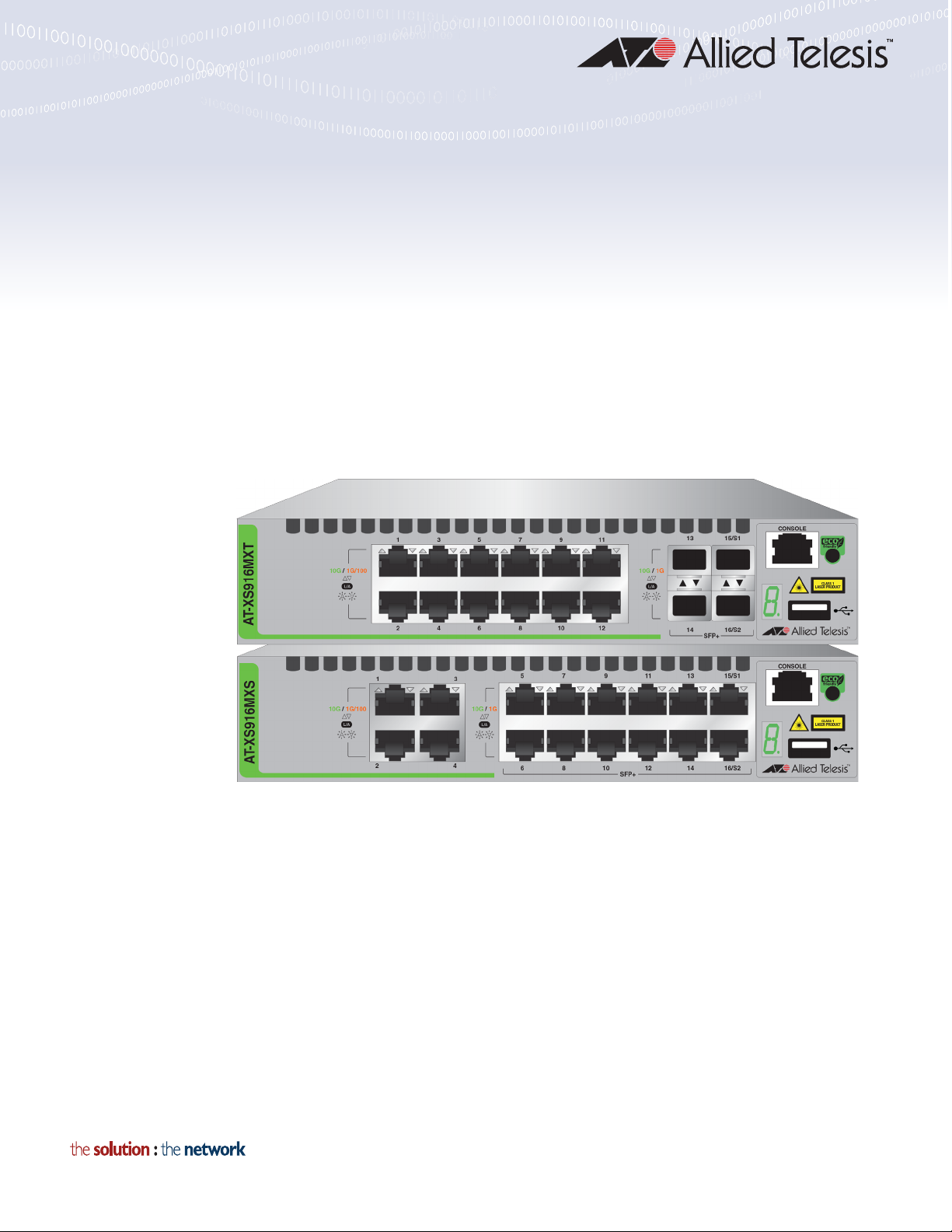
XS916MX Series
10 GIGABIT ETHERNET SWITCHES
AT-XS916MXT
AT-XS916MXS
Installation Guide for Stand-alone
Switches
613-002257 Rev. B

Copyright 2016 Allied Telesis, Inc.
All rights reserved. No part of this publication may be reproduced without prior written permission from Allied Telesis, Inc.
Allied Telesis and the Allied Telesis logo are trademarks of Allied Telesis, Incorporated. All other product names, company names,
logos or other designations mentioned herein are trademarks or registered trademarks of their respective owners.
Allied Telesis, Inc. reserves the right to make changes in specifications and other information contained in this document without prior
written notice. The information provided herein is subject to change without notice. In no event shall Allied Telesis, Inc. be liable for
any incidental, special, indirect, or consequential damages whatsoever, including but not limited to lost profits, arising out of or related
to this manual or the information contained herein, even if Allied Telesis, Inc. has been advised of, known, or should have known, the
possibility of such damages.

Electrical Safety and Emissions
Note
Note
Standards
This section contains the following:
“US Federal Communications Commission”
“Industry Canada”
“Emissions, Immunity and Electrical Safety Standards” on page 4
“Translated Safety Statements” on page 4
US Federal Communications Commission
Radiated Energy
This equipment has been tested and found to comply with the limits for a Class A digital device
pursuant to Part 15 of FCC Rules. These limits are designed to provide reasonable protection
against harmful interference when the equipment is operated in a commercial environment.
This equipment generates, uses, and can radiate radio frequency energy and, if not installed
and used in accordance with this instruction manual, may cause harmful interference to radio
communications. Operation of this equipment in a residential area is likely to cause harmful
interference in which case the user will be required to correct the interference at his own
expense.
Modifications or changes not expressly approved of by the manufacturer or the FCC, can void
your right to operate this equipment.
Industry Canada
Radiated Energy
This Class A digital apparatus complies with Canadian ICES-003.
Cet appareil numérique de la classe A est conforme à la norme NMB-003 du Canada.
3
Emissions, Immunity and Electrical Safety Standards
Warning
Warning
RFI Emissions FCC Class A, EN55022 Class A, EN61000-3-2, EN61000-3-3, VCCI Class A,
RCM
In a domestic environment this product may cause radio interference in which case the user
may be required to take adequate measures. E70
EMC (Immunity) EN55024
Electrical Safety UL 60950-1 (
EN60825-1 (TUV)
Laser Safety: EN60825 L7
CULUS
), CSA-C22 No. 60950-1 (CULUS), EN60950-1 (TUV),
Translated Safety Statements
Important: The indicates that translations of the safety statement are available in the PDF
document “Translated Safety Statements” posted on the Allied Telesis website at
alliedtelesis.com/support.
4

Contents
Preface ............................................................................................................................................................................. 11
Document Conventions ................................................................................................................................................12
Contacting Allied Telesis ..............................................................................................................................................13
Chapter 1: Overview ........................................................................................................................................................ 15
Features .......................................................................................................................................................................16
XS916MX Models .................................................................................................................................................16
100/1000/10000 Mbps Twisted Pair Ports ............................................................................................................16
SFP/SFP+ Slots ....................................................................................................................................................16
S1 and S2 Stacking Ports .....................................................................................................................................16
LEDs .....................................................................................................................................................................16
Installation Options................................................................................................................................................16
MAC Address Table ..............................................................................................................................................17
Management Software and Interfaces ..................................................................................................................17
Management Methods ..........................................................................................................................................17
Front Panels .................................................................................................................................................................18
Management Panel ......................................................................................................................................................19
100/1000/10000Base-T and Twisted Pair Ports...........................................................................................................20
Speed....................................................................................................................................................................20
Duplex Mode .........................................................................................................................................................20
Wiring Configuration..............................................................................................................................................20
Maximum Distance................................................................................................................................................20
Port Pinouts...........................................................................................................................................................20
Cable Requirements .............................................................................................................................................21
SFP/SFP+ Slots ...........................................................................................................................................................22
Stacking Slots...............................................................................................................................................................23
eco-friendly Button .......................................................................................................................................................24
LEDs...........................................................................................................................
LEDs for the Twisted Pair Ports ............................................................................................................................25
LEDs for the SFP Slots .........................................................................................................................................25
LEDs for the Stacking Slots ..................................................................................................................................26
Switch ID LED .......................................................................................................................................................27
USB Port ......................................................................................................................................................................29
Console Port.................................................................................................................................................................30
Power Supply ...............................................................................................................................................................31
..................................................25
Chapter 2: Beginning the Installation ............................................................................................................................ 33
Reviewing Safety Precautions......................................................................................................................................34
Choosing a Site for the Switch .....................................................................................................................................38
Unpacking the Switch...................................................................................................................................................39
Chapter 3: Installing the Switch ..................................................................................................................................... 41
Installing the Switch on a Table....................................................................................................................................42
Installing the Switch in an Equipment Rack..................................................................................................................43
Installing Two Switches in One Row .....................................................................................................................43
Installing a Switch in One Row..............................................................................................................................43
Installing the Switch on a Wall......................................................................................................................................46
What to Prepare for Wall Installation.....................................................................................................................46
Installing the Switch on a Wall ..............................................................................................................................47
Chapter 4: Cabling the Networking Ports ...................................................................................................................... 49
5

Contents
Cabling the Twisted Pair Ports .................................................................................................................................... 50
Installing SFP/SFP+ Transceivers............................................................................................................................... 51
Guidelines for SFP/SFP+ Transceivers................................................................................................................ 51
Installing SFP/SFP+ Transceivers........................................................................................................................ 52
Chapter 5: Powering On the Switch ...............................................................................................................................55
Powering On the Switch .............................................................................................................................................. 56
Monitoring the Initialization Processes ........................................................................................................................ 58
Configuring the Switch for Stand-alone Operations..................................................................................................... 61
Starting a Local Management Session................................................................................................................. 61
Disabling VCStack................................................................................................................................................ 63
Specifying Ports in the Command Line Interface for Stand-alone Switches................................................................ 66
Chapter 6: Troubleshooting ............................................................................................................................................ 67
Appendix A: Technical Specifications ........................................................................................................................... 71
Physical Specifications ................................................................................................................................................ 71
Environmental Specifications....................................................................................................................................... 72
Power Specifications ................................................................................................................................................... 72
Certifications................................................................................................................................................................ 73
RJ-45 Twisted Pair Port Pinouts.................................................................................................................................. 74
RJ-45 Style Serial Console Port Pinouts ..................................................................................................................... 75
6

Tables
Table 1: Twisted Pair Cable for the 100/1000/10000Base-T Ports .....................................................................................21
Table 2: LEDs on the Twisted Pair Ports on the XS916MX Series Switch ..........................................................................25
Table 3: SFP Slot LEDs on the XS916MX Series Switch ....................................................................................................26
Table 4: S1 and S2 Slot LEDs .............................................................................................................................................27
Table 5: Components in the Shipping Box ..........................................................................................................................39
Table 6: Product Dimensions ...............................................................................................................................................71
Table 7: Product Weights ....................................................................................................................................................71
Table 8: Ventilation Requirements .......................................................................................................................................71
Table 9: Environmental Specifications .................................................................................................................................72
Table 10: Input Voltages ......................................................................................................................................................72
Table 11: Maximum Power Consumption ............................................................................................................................72
Table 12: Heat Dissipation ..................................................................................................................................................72
Table 13: Product Certifications ...........................................................................................................................................73
Table 14: Pin Signals for 10 and 100 Mbps .........................................................................................................................74
Table 15: Pin Signals for 1000 Mbps ...................................................................................................................................74
Table 16: RJ-45 Style Serial Console Port Pin Signals .......................................................................................................75
7

Tables
8

Figures
Figure 17: AT-XS916MXT Switch Front Panel .....................................................................................................................18
Figure 18: AT-XS916MXS Switch Front Panel .....................................................................................................................18
Figure 19: XS916MX Series Management Panel.................................................................................................................19
Figure 20: Stacking Transceiver...........................................................................................................................................23
Figure 21: LEDs for the Twisted Pair Ports on the XS916MX Series Switch .......................................................................25
Figure 22: SFP Slot LEDs ....................................................................................................................................................26
Figure 23: Switch ID LED .....................................................................................................................................................27
Figure 24: Switch ID LED Not in Low Power Mode ..............................................................................................................28
Figure 25: Switch ID LEDs in Low Power Mode...................................................................................................................28
Figure 26: Rack Installation Options for the XS916MXSeries Switch...................................................................................43
Figure 27: Turning the Switch Upside Down ........................................................................................................................44
Figure 28: Removing the Rubber Feet .................................................................................................................................44
Figure 29: Attaching the Handles to the Brackets ................................................................................................................44
Figure 30: Installing the Brackets on the Switch...................................................................................................................45
Figure 31: Mounting the Switch in an Equipment Rack ........................................................................................................45
Figure 32: Positions of the XS916MX Series Switch on a Wall ............................................................................................46
Figure 33: Turning the Switch Upside Down ........................................................................................................................47
Figure 34: Removing the Rubber Feet .................................................................................................................................47
Figure 35: Attaching the Wall Brackets.................................................................................................................................47
Figure 36: Installing the Switch on the Wall..........................................................................................................................48
Figure 37: Removing the Dust Plug from an SFP/SFP+ Slot ...............................................................................................52
Figure 38: Installing an SFP/SFP+ Transceiver ...................................................................................................................52
Figure 39: Removing the Dust Cover from an SFP Transceiver ..........................................................................................53
Figure 40: Positioning the SFP Handle in the Upright Position ............................................................................................53
Figure 41: Connecting a Fiber Optic Cable to an SFP Transceiver......................................................................................54
Figure 42: Installing the Retaining Clip .................................................................................................................................56
Figure 43: Raising the Retaining Clip ...................................................................................................................................56
Figure 44: Plugging in the AC Power Cord.......................................................................................
Figure 45: Lowering the Retaining Clip.................................................................................................................................57
Figure 46: Switch Initialization Messages.............................................................................................................................58
Figure 47: Switch Initialization Messages (Continued).........................................................................................................59
Figure 48: Switch Initialization Messages (Continued).........................................................................................................60
Figure 49: Connecting the Management Cable to the Console Port ....................................................................................62
Figure 50: User Exec Mode Prompt .....................................................................................................................................63
Figure 51: SHOW STACK Command...................................................................................................................................63
Figure 52: Moving to the Global Configuration Mode ...........................................................................................................64
Figure 53: Confirmation Prompt for the NO STACK ENABLE Command............................................................................64
Figure 54: Returning to the Privileged Exec Mode ...............................................................................................................65
Figure 55: Saving the Changes with the WRITE Command.................................................................................................65
Figure 56: PORT Parameter in the Command Line Interface...............................................................................................66
Figure 57: RJ-45 Socket Pin Layout (Front View) ................................................................................................................74
....................................57
9

Figures
10

Preface
Note
This guide contains the installation instructions for the XS916MX Series of
Layer 2+ 10 Gigabit Ethernet switches. This preface contains the following
sections:
“Document Conventions” on page 12
“Contacting Allied Telesis” on page 13
This guide explains how to install the switches as stand-alone units.
For instructions on how to install them in a stack configuration with
Virtual Chassis Stacking (VCStack
Installation Guide for VCStack.
™), see the XS916MX Series
11
Preface
Note
Caution
Warning
Document Conventions
This document uses the following conventions:
Notes provide additional information.
Cautions inform you that performing or omitting a specific action
may result in equipment damage or loss of data.
Warnings inform you that performing or omitting a specific action
may result in bodily injury.
12

Contacting Allied Telesis
If you need assistance with this product, you may contact Allied Telesis
technical support by going to the Support & Services section of the Allied
Telesis web site at www.alliedtelesis.com/support. You can find links for
the following services on this page:
24/7 Online Support — Enter our interactive support center to
search for answers to your product questions in our knowledge
database, to check support tickets, to learn about RMAs, and to
contact Allied Telesis technical experts.
USA and EMEA phone support — Select the phone number that
best fits your location and customer type.
Hardware warranty information — Learn about Allied Telesis
warranties and register your product online.
Replacement Services — Submit a Return Merchandise
Authorization (RMA) request via our interactive support center.
XS916MX Series Installation Guide for Stand-alone Switches
Documentation — View the most recent installation and user
guides, software release notes, white papers, and data sheets for
your products.
Software Downloads — Download the latest software releases for
your managed products.
For sales or corporate information, go to www.alliedtelesis.com/
purchase and select your region.
13

Preface
14

Chapter 1
Note
Overview
This chapter contains the following sections:
“Features” on page 16
“Front Panels” on page 18
“Management Panel” on page 19
“100/1000/10000Base-T and Twisted Pair Ports” on page 20
“SFP/SFP+ Slots” on page 22
“Stacking Slots” on page 23
“eco-friendly Button” on page 24
“LEDs” on page 25
“USB Port” on page 29
“Console Port” on page 30
“Power Supply” on page 31
This guide explains how to install the switches as stand-alone units.
For instructions on how to install them in a stack configuration with
Virtual Chassis Stacking (VCStack
Installation Guide for VCStack.
™), see the XS916MX Series
15

Chapter 1: Overview
Features
The XS916MX series switches and their features are listed in this section:
XS916MX
Models
100/1000/10000
Mbps Twisted
Pair Ports
Here are model names of the XS916MX Series switches:
AT-XS916MXT
AT-XS916MXS
Here are the basic features of the 100/1000/10000 Mbps twisted pair
ports:
4 or 12 ports per switch
100Base-TX, 1000Base-T, 1000Base-SX, and 10GBASE-T
compliant
IEEE 802.3u Auto-Negotiation compliant
Auto-MDI/MDIX
100 meters (328 feet) maximum operating distance
IEEE 802.3x flow control in full-duplex mode
IEEE 802.3ab 1000Base-T
IEEE 802.3an 10GBase-T
Jumbo frames up to 9KB
RJ-45 connectors
SFP/SFP+ Slots The XS916MX series switch has two SFP/SFP+ slots: S1 and S2 Stacking
Slots. For more information, see “SFP/SFP+ Slots” on page 22.
S1 and S2
Stacking Ports
The S1 and S2 slots are stacking ports for the VCStack feature. You can
use the slots to build a stack of two switches. For more information, see
the “Stacking Slots” on page 23.
LEDs Here are the port LEDs:
Link/activity LEDs for the twisted pair ports
Link/activity LEDs for SFP/SFP+ slots
Switch ID number LED
eco-friendly button turns off the LEDs to conserve electricity
Installation
Options
16
Here are the installation options for the switches:
Desk or tabletop
19-inch equipment rack

Wall
XS916MX Series Installation Guide for Stand-alone Switches
MAC Address
Table
Management
Software and
Interfaces
Management
Methods
Here are the basic features of the MAC address tables of the switches:
Storage capacity of 16,000 dynamic MAC address entries
Storage capacity of 256 static MAC address entries
Automatic learning and aging
Here are the management software and interfaces:
AlliedWare Plus Management Software
Command line interface
Here are the methods for managing the switches:
Local management through the Console port
Remote Telnet and Secure Shell management
SNMPv1, v2c, and v3
17
Chapter 1: Overview
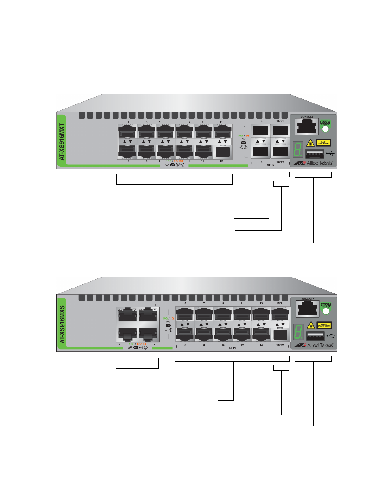
100/1000/10000Base-T Ports
SFP Slots
Stacking Slots
Management Panel
100/1000/10000Base-T Ports
SFP Slots
Stacking Slots
Management Panel
Front Panels
The front panels of the XS916MX Series switches are shown in Figure 1
and Figure 2.
Figure 1. AT-XS916MXT Switch Front Panel
Figure 2. AT-XS916MXS Switch Front Panel
18
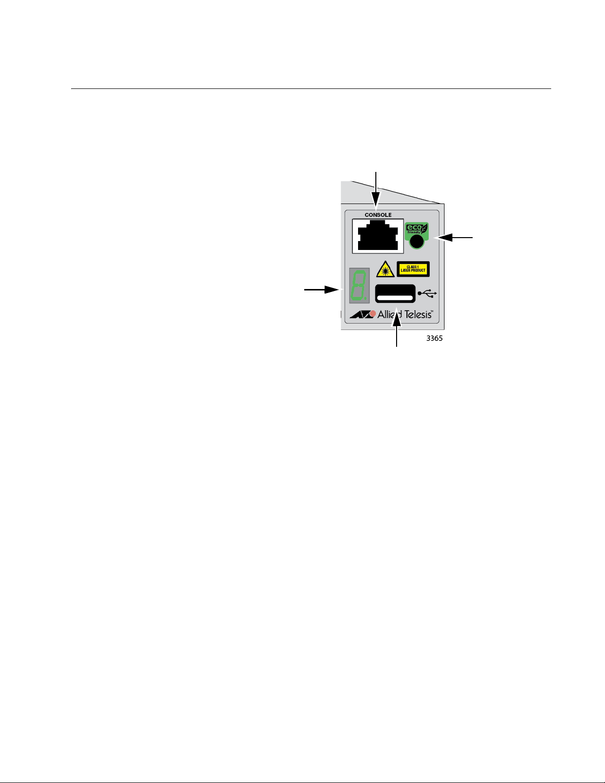
Management Panel
eco-friendly
button
USB Port
Switch ID LED
Console Management Port
XS916MX Series Installation Guide for Stand-alone Switches
Figure 3 identifies the components in the management panels on the
XS916MX Series switches.
Figure 3. XS916MX Series Management Panel
19

Chapter 1: Overview
100/1000/10000Base-T and Twisted Pair Ports
The XS916MXT series switches have 4 or 12 100/1000/10000Base-T
ports.
Speed The ports can operate at 100 or 1000 Mbps, or 10 Gbps. The speeds may
be set manually using the management software or automatically with
Auto-Negotiation (IEEE 802.3u), the default setting.
Duplex Mode The twisted pair ports operate in full-duplex mode. You cannot change the
duplex mode of a port manually.
Wiring
Configuration
Maximum
The wiring configuration of a port operating at 100 Mbps can be MDI or
MDI-X. The wiring configurations of a switch port and a network device
connected with straight-through twisted pair cabling have to be opposite,
such that one device is using MDI and the other MDI-X. For instance, a
switch port has to be set to MDI-X if it is connected to a network device set
to MDI.
The switch has the auto-MDI/MDI-X detection feature (IEEE 802.3abcompliant) so that the switch automatically negotiates with network
devices to establish their proper settings.
The ports have a maximum operating distance of 100 meters (328 feet).
Distance
Port Pinouts See Table 14 on page 74 and Table 15 on page 74 for the port pinouts of
the 100/1000/10000Base-T twisted pair ports.
20

XS916MX Series Installation Guide for Stand-alone Switches
Cable
Requirements
The cable requirements of the ports are given in Table 1.
Table 1. Twisted Pair Cable for the 100/1000/10000Base-T Ports
Cable Type 100Mbps 1000Mbps 10Gbps
Standard TIA/EIA 568-Bcompliant Category 3 shielded
or unshielded cabling with 100
ohm impedance and a
frequency of 16 MHz.
Standard TIA/EIA 568-Acompliant Category 5 or TIA/
EIA 568-B-compliant Enhanced
Category 5 (Cat 5e) shielded or
unshielded cabling with 100
ohm impedance and a
frequency of 100 MHz.
Standard TIA/EIA 568-Bcompliant Category 6 or 6a
shielded cabling.
Yes No No
Yes Yes Yes
Yes Yes Yes
21

Chapter 1: Overview
Note
SFP/SFP+ Slots
The XS916MX series switch has two SFP/SFP+ slots.You may use the
transceivers to connect switches to other network devices over large
distances, build high-speed backbone networks between network devices,
or connect high-speed devices, such as servers, to your network.
Here is a list of supported pluggable transceivers:
AT-SP10SR/I
AT-SP10LR
AT-SP10LR/I
AT-SP10LRM
AT-SP10LR20/I
AT-SP10LR40/I
AT-SP10ZR80/I
AT-SP10ER40/I
AT-SPTXa
AT-SPSX
AT-SPSX2
AT-SPEX
AT-SPLX10
AT-SPLX40
AT-SP10TW
AT-StackXS/1.0
SFP/SFP+ transceivers must be purchased separately.
22
Stacking Slots
Note
Note
Note
XS916MX Series Installation Guide for Stand-alone Switches
The S1 and S2 slots on the front panel of the switch are used with special
stacking transceivers to create a VCStack of two switches.
Here is a list of supported stacking transceivers:
AT-SP10TW
AT-StackXS/1.0
Stacking cables must be purchased separately.
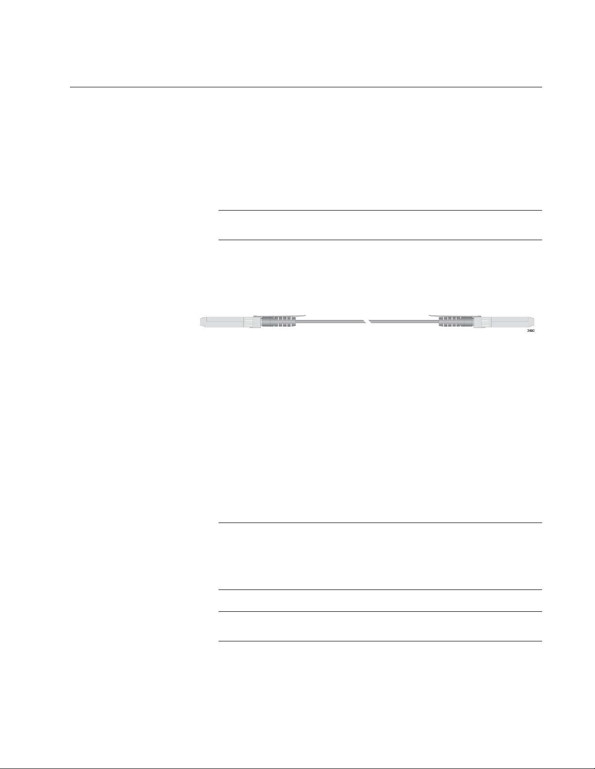
The stacking transceiver AT-SP10TW is shown in Figure 4 as an example.
It has two SFP transceiver-style connectors and one meter of twinax
cable.
Figure 4. Stacking Transceiver
The switches of a VCStack act as a single virtual unit. They synchronize
their actions so that switching operations, like spanning tree protocols,
virtual LANs, and static port trunks, span across all the units and ports.
The two main advantages of stacks are:
You can manage multiple units simultaneously, which can simplify
network management.
You have more flexibility with some of the features. For instance, a
static port trunk on a stand-alone switch has to consist of ports
from the same switch. In contrast, a static trunk on a stack may
consist of ports from different switches in the same stack.
This guide explains how to install the devices as stand-alone units.
For instructions on how to install the switches in a stack with Virtual
Chassis Stacking (VCStack), refer to the XS916MX Series
Installation Guide for VCStack.
The stacking slots may be used as regular networking ports.
23
 Loading...