

Page 1
x930 Series
Gigabit Layer 3 Ethernet Switches
AT-x930-28GTX
AT-x930-28GPX
AT-x930-28GSTX
AT-x930-52GTX
AT-x930-52GPX
Installation Guide for Stand-alone
Switches
613-002100 Rev. C
Page 2

Copyright © 2015 Allied Telesis, Inc.
All rights reserved. No part of this publication may be reproduced without prior written permission from Allied Telesis, Inc.
Allied Telesis, VCStack, and the Allied Telesis logo are trademarks of Allied Telesis, Incorporated. All other product names, company
names, logos or other designations mentioned herein are trademarks or registered trademarks of their respective owners.
Allied Telesis, Inc. reserves the right to make changes in specifications and other information contained in this document without prior
written notice. The information provided herein is subject to change without notice. In no event shall Allied Telesis, Inc. be liable for
any incidental, special, indirect, or consequential damages whatsoever, including but not limited to lost profits, arising out of or related
to this manual or the information contained herein, even if Allied Telesis, Inc. has been advised of, known, or should have known, the
possibility of such damages.
Page 3

Electrical Safety and Emissions Standards
Laser Safety EN60825
This product meets the following standards.
U.S. Federal Communications Commission
Radiated Energy
Note: This equipment has been tested and found to comply with the limits for a Class A digital device pursuant to Part 15
of FCC Rules. These limits are designed to provide reasonable protection against harmful interference when the
equipment is operated in a commercial environment. This equipment generates, uses , and can radiate radio frequency
energy and, if not installed and used in accordance with this instruction manual, may cause harmful interference to radio
communications. Operation of this equipment in a residential area is likely to cause harmful interference in which case
the user will be required to correct the interference at his own expense.
Note: Modifications or changes not expressly approved of by the manufacturer or the FCC, can void your right to operate
this equipment.
Industry Canada
This Class A digital apparatus complies with Canadian ICES-003.
Cet appareil numérique de la classe A est conforme à la norme NMB-003 du Canada.
RFI Emissions: FCC Class A, EN55022 Class A, EN61000-3-2, EN61000-3-3, VCCI Class A,
C-TICK, CE
Warning: In a domestic environment this product may cause radio interference in which case
the user may be required to take adequate measures.
EMC (Immunity): EN55024
Electrical Safety: EN60950-1 (TUV), UL 60950-1 (
CULUS
)
3
Page 4

Translated Safety Statements
Important: Safety statements that have the symbol are translated into multiple languages in the
Translated Safety Statements document at www.alliedtelesis.com/support.
4
Page 5

Contents
Preface ...............................................................................................................................................................................11
Document Conventions .......................................................................................................................................................12
Contacting Allied Telesis .....................................................................................................................................................13
Chapter 1: Overview ........................................................................................................................................................ 15
Models.................................................................................................................................................................................16
Features ..............................................................................................................................................................................17
x930 Models......... ... .. ...................................................................................................................................................17
10/100/1000 Mbps Twisted Pair Ports .........................................................................................................................17
Power Over Ethernet....................................................................................................................................................17
SFP Slots .....................................................................................................................................................................17
SFP+ Slots .......................................................................................................... ... ......................................................18
S1 and S2 Stacking Slots.............................................................................................................................................19
LEDs.............................................................................................................................................................................19
Optional Expansion Cards............................................................................................................................................19
Installation Options.......................................................................................................................................................19
MAC Address Table ...................................................................... ...............................................................................19
Management Software and Interfaces .........................................................................................................................20
Management Methods..................................................................................................................................................20
Power Supplies ............................................................................................................................................................20
Front and Back Panels........................................................................................................................................................21
Management Panel .............................................................................................................................................................24
Power Supplies....................................................................................................................................................................25
Guidelines ....................................................................................................................................................................27
10/100/1000Base-T Twisted Pair Ports...........................................................................................
Speed...........................................................................................................................................................................29
Duplex Mode................................................................................................................................................................29
Wiring Configuration.....................................................................................................................................................29
Maximum Distance.......................................................................................................................................................30
Cable Requirements.....................................................................................................................................................30
Port Pinouts........................................... ..................................... ..................................................................................30
Power Over Ethernet...........................................................................................................................................................31
PoE Standards.............................................................................................................................................................31
Powered Device Classes .............................................................................................................................................31
Cable Requirements.....................................................................................................................................................32
Power Budget...............................................................................................................................................................33
Port Prioritization..........................................................................................................................................................35
Wiring Implementation..................................................................................................................................................36
SFP Slots.............................................................................................................................................................................37
SFP+ Slots..................................................................... ... ...................................................................................................38
Stacking S1 and S2 SFP+ Slots..........................................................................................................................................39
Ethernet Management Port (NET MGMT) . ..........................................................................................................................40
NET MGMT LEDs ........................................................................................................................................................40
eco-friendly Button...............................................................................................................................................................41
LEDs....................................................................................................................................................................................42
LEDs for the Twisted Pair Ports...................................................................................................................................42
LEDs for the SFP Slots ................................................................................................................................................45
LEDs for the SFP+ Slots ..............................................................................................................................................46
LEDs for the Stacking Slots..........................................................................................................................................47
....................................29
5
Page 6

Contents
Switch ID LED ............................................................................................................................................................. 48
USB Port........................................... ................................................................... ... ............................................................ 50
Console Port....................................................................................................................................................................... 51
Optional Cards.................................................................................................................................................................... 52
AT-StackQS Card........................................................................................................................................................ 52
AT-x9EM/XT4 Card.....................................................................................................................................................53
Chapter 2: Beginning the Installation ............................................................................................................................55
Reviewing Safety Precautions............................................................................................................................................ 56
Choosing a Site for the Switch............................................................................................................................................61
Unpacking the Switch .........................................................................................................................................................62
Chapter 3: Installing the Power Supplies ......................................................................................................................65
Installing the Power Supplies..............................................................................................................................................66
Installing a Blank Power Supply Slot Cover........................................................................................................................72
Chapter 4: Installing the AT-x9EM/XT4 Card .................................................................................................................75
Guidelines........................................................................................................................................................................... 76
Installing the AT-x9EM/XT4 Card .......................................................................................................................................77
Chapter 5: Installing the Switch on a Table ...................................................................................................................87
Chapter 6: Installing the Switch in an Equipment Rack ...............................................................................................89
Required Items ....................................................... ............................................................................................................ 90
Installing the Switch in an Equipment Rack........................................................................................................................ 91
Chapter 7: Installing the Switch on a Wall .....................................................................................................................95
Switch Orientation on the Wall............................................................................................................................................96
Recommended Minimum Wall Area Dimensions................................................................................................................97
Plywood Base for a Wall with Wooden Studs..................................................................................................................... 99
Installation Guidelines....................................................................................................................................................... 101
Tools and Material..................................................................................................................................................... 101
Installing the Plywood Base....................................................................................................
Installing the Switch on the Plywood Base ....................................................................................................................... 104
Installing the Switch on a Concrete Wall........................................................................................................................... 107
.......................................... 103
Chapter 8: Wiring the DC Connector on the AT-PWR250-80 Power Supply ............................................................111
Chapter 9: Powering On the Switch .............................................................................................................................115
Powering On AC Power Supplies.....................................................................................................................................116
Powering On the AT-PWR250-80 DC Power Supply ....................................................................................................... 120
Monitoring the Initialization Processes..............................................................................................................................122
Chapter 10: Configuring the Switch for Stand-alone Operation ...............................................................................125
Determining the Status of the Switch................................................................................................................................126
Starting a Local Management Session.............................................................................................................................127
Disabling VCStack............................................... ..................................... ........................................................................ 129
Verifying Support for Hardware Options...........................................................................................................................132
Chapter 11: Cabling the Networking Ports ..................................................................................................................133
Cabling the Twisted Pair Ports.......................................................................................................................................... 134
Guidelines to Handling SFP or SFP+ Transceivers.......................................................................................................... 136
Installing SFP or SFP+ Transceivers................................................................................................................................ 137
Specifying Ports in the Command Line Interface for Stand-alone Switches..................................................................... 141
Chapter 12: Troubleshooting ........................................................................................................................................143
Appendix A: Technical Specifications .........................................................................................................................149
Physical Specifications ..................................................................................................................................................... 150
Environmental Specifications............................................................................................................................................ 152
Power Specifications......................................................................................................................................................... 153
Certifications.....................................................................................................................................................................155
RJ-45 Twisted Pair Port Pinouts.......................................................................................................................................156
RJ-45 Style Serial Console Port Pinouts.......................................................................................................................... 158
6
Page 7

Figures
Figure 1: Front Panels of the AT-x930-28GTX and AT-x930-28GPX Switches...................................................................21
Figure 2: Front Panels of the AT-x930-28GSTX, AT-x930-52GTX, and AT-x930-52GPX Switches....................................22
Figure 3: Back Panel............................................................................................................................................................23
Figure 4: Management Panel ...............................................................................................................................................24
Figure 5: AT-PWR150 and AT-PWR250 Power Supplies....................................................................................................25
Figure 6: AT-PWR250-80 Power Supply..............................................................................................................................26
Figure 7: AT-PWR800 Power Supply...................................................................................................................................26
Figure 8: AT-PWR1200 Power Supply.................................................................................................................................27
Figure 9: LEDs for the 10/100/1000Base-T Ports on the AT-x930-28GTX, AT-x930-28GSTX, and AT-x930-5 2GTX
Switches ...............................................................................................................................................................................42
Figure 10: LEDs for the 10/100/1000Base-T Ports on the AT-x930-28GPX and AT-x930-52GPX Switches ......................44
Figure 11: SFP Slot LEDs ....................................................................................................................................................45
Figure 12: SFP+ Slot LEDs ..................................................................................................................................................46
Figure 13: Switch ID LED.....................................................................................................................................................48
Figure 14: Switch ID LED.....................................................................................................................................................48
Figure 15: Switch ID LEDs in the Low Power Mode.............................................................................................................49
Figure 16: Optional AT-StackQS Card .................................................................................................................................52
Figure 17: Optional AT-x9EM/XT4 Card...............................................................................................................................53
Figure 18: Accessory Kit.......................................................................................................................................................62
Figure 19: Pre-installed Items...............................................................................................................................................63
Figure 20: Removing the AT-PNL250 Blank Panel ..............................................................................................................67
Figure 21: Power Supply Accessory Items...........................................................................................................................68
Figure 22: Installing a Power Supply ....................................................................................................................................69
Figure 23: Improper Installation of a Power Supply..............................................................................................................70
Figure 24: Tightening the Captive Screws on the Power Supply..........................................................................................70
Figure 25: Installing the Power Cord Retaining Clip............................................................................
Figure 26: Installing a Blank Panel on a Power Supply Slot.................................................................................................72
Figure 27: Tightening the Captive Screws on the Power Supply Blank Panel .....................................................................73
Figure 28: Loosening the Two Captive Screws on the AT-FAN09 Module ..........................................................................78
Figure 29: Removing the AT-FAN09 Module........................................................................................................................79
Figure 30: Loosening the Captive Screw on the AT-FAN09ADP Module.............................................................................80
Figure 31: Removing the AT-FAN09ADP Module................................................................................................................ 81
Figure 32: Removing the AT-x9EM/XT4 Card from the Anti-static Bag............................................... ... ..............................81
Figure 33: Aligning the AT-x9EM/XT4 Card in the Slot ........................................................................................................82
Figure 34: Seating the AT-x9EM/XT4 Card in the Switch.....................................................................................................83
Figure 35: Tightening the Captive Screw on the AT-x9EM/XT4 Card..................................................................................83
Figure 36: Aligning the AT-FAN09 Module in the Slot..........................................................................................................84
Figure 37: Tightening the Two Captive Screws on the AT-FAN09 Module..........................................................................85
Figure 38: Storing the AT-FAN09ADP Module in an Anti-static Bag............................................................ ........................85
Figure 39: Installing the Bumper Feet...................................................................................................................................87
Figure 40: Attaching the Equipment Rack Brackets.............................................................................................................92
Figure 41: Attaching the Equipment Rack Brackets (Continued) .........................................................................................93
Figure 42: Installing the Switch in an Equipment Rack.........................................................................................................94
Figure 43: Positions of the Switch on the Wall.....................................................................................................................96
Figure 44: Minimum Wall Area Dimensions with the Front Panel on the Left.......................................................................97
Figure 45: Minimum Wall Area Dimensions with the Front Panel on the Right....................................................................98
Figure 46: Switch on the Wall with a Plywood Base.............................................................................................................99
Figure 47: Steps to Installing the Switch with a Plywood Base ..........................................................................................100
Figure 48: Installing the Brackets to the Switch for Wall Installation ..................................................................................104
.................................71
7
Page 8

Figures
Figure 49: Mounting Holes..................................................................................................................................................105
Figure 50: Securing the Switch to the Plywood Base.........................................................................................................106
Figure 51: Marking the Locations of the Bracket Holes on a Concrete Wall............................................ ... ........................108
Figure 52: Installing the Switch on a Concrete Wall ...........................................................................................................109
Figure 53: On/Off Switch on AT-PWR250-80 Power Supply..............................................................................................112
Figure 54: DC Terminal Block.............................................................................................................................................112
Figure 55: Stripped Wire.....................................................................................................................................................113
Figure 56: Connecting the Ground Wire to the DC Terminal Block ................................................................. ...................113
Figure 57: Raising the Power Cord Retaining Clip .............................................................................................................117
Figure 58: Connecting the AC Power Cord.........................................................................................................................118
Figure 59: Lowering the Power Cord Retaining Clip...........................................................................................................119
Figure 60: On/Off Switch on the AT-PWR250-80 DC Power Supply..................................................................................120
Figure 61: Switch Initialization Messages...........................................................................................................................122
Figure 62: Switch Initialization Messages (Continued) .......................................................................................................123
Figure 63: Switch Initialization Messages (Continued) .......................................................................................................124
Figure 64: Connecting the Management Cable to the Console Port ..................................................................................127
Figure 65: User Exec Mode Prompt....................................................................................................................................129
Figure 66: SHOW STACK Command.................................................................................................................................129
Figure 67: Moving to the Global Configuration Mode.........................................................................................................130
Figure 68: Confirmation Prompt for the NO STACK ENABLE Command..........................................................................130
Figure 69: Disabling VCStack.............................................................................................................................................131
Figure 70: Returning to the Privileged Exec Mode .............................................................................................................131
Figure 71: Saving the Changes with the WRITE Command...............................................................................................131
Figure 72: Removing the Dust Plug from an SFP Slot.............................................................................
Figure 73: Installing an SFP Transceiver............................................................................................................................138
Figure 74: Removing the Dust Cover from an SFP or SFP+ Transceiver..........................................................................138
Figure 75: Positioning the SFP or SFP+ Handle in the Upright Position ............................................................................139
Figure 76: Connecting a Fiber Optic Cable to an SFP or SFP+ Transceiver ........................................................ .............140
Figure 77: PORT Parameter in the Command Line Interface.............................................................................................141
Figure 78: RJ-45 Socket Pin Layout (Front View)...............................................................................................................156
...........................137
8
Page 9

Tables
Table 1: Models and Basic Features ...................................................................................................................................16
Table 2: Twisted Pair Cable for the 10/100/1000Base-T Ports ...........................................................................................30
Table 3: IEEE Powered Device Classes ..............................................................................................................................32
Table 4: Twisted Pair Cable Requirements for the 10/100/1000Base-T Ports at 10 or 100Mbps .......................................32
Table 5: Twisted Pair Cable Requirements for the 10/100/1000Base-T Ports at 1000Mbps ..............................................33
Table 6: Power Supply Budgets of the Power Supplies ......................................................................................................33
Table 7: Power Budgets of the AT-PWR800 Power Supply ................................................................................................34
Table 8: Power Budgets of the AT-PWR1200 Power Supply ..............................................................................................35
Table 9: NET MGMT Port LED ............................................................................................................................................40
Table 10: LEDs on the 10/100/1000Base-T Ports on the AT-x930-28GTX, AT -x930-28GSTX, and AT-x930-52GTX
Switches ..............................................................................................................................................................................43
Table 11: LEDs on the 10/100/1000Base-T Ports on the AT-x930-28GPX and AT-x930-52GPX Switches .......................44
Table 12: SFP Slot LEDs on the AT-x930-28GSTX Switch .................................................................................................46
Table 13: SFP+ Slot LEDs ...................................................................................................................................................47
Table 14: Stacking Slot LEDs ..............................................................................................................................................47
Table 15: AT-StackQS Card LEDs ......................................................................................................................................52
Table 16: Twisted Pair Cable for the AT-x9EM/XT4 Card ...................................................................................................53
Table 17: AT-x9EM/XT4 Card LEDs ....................................................................................................................................54
Table 18: Accessory Items Included with the Power Supplies ............................................................................................68
Table 19: PORT Parameter Format ................................................................................................................................... 141
Table 20: Product Dimensions ...........................................................................................................................................150
Table 21: Product Weights ................................................................................................................................................150
Table 22: Ventilation Requirements ................................................................................................................................... 151
Table 23: Environmental Specifications .............................................................................................................................152
Table 24: Maximum Power Consumption with the AT-PWR150, AT-PWR250 or AT-PWR250-80 Power Supply ...........153
Table 25: Maximum Power Consumption with the AT-PWR800 Power Supply ................................................................ 153
Table 26: Maximum Power Consumption with the AT-PWR1200 Power Supply ..........................................................
Table 27: Input Voltages ....................................................................................................................................................154
Table 28: Product Certifications .........................................................................................................................................155
Table 29: Pin Signals for 10 and 100 Mbps .......................................................................................................................156
Table 30: Pin Signals for 1000 Mbps .................................................................................................................................156
Table 31: RJ-45 Style Serial Console Port Pin Signals .....................................................................................................158
.... 153
9
Page 10

Tables
10
Page 11

Preface
Note
This guide contains the installation instructions for the x930 Series of
Layer 3, Gigabit Ethernet switches. This preface contains the following
sections:
“Document Conventions” on page 12
“Contacting Allied Telesis” on page 13
This guide explains how to install the switches as stand-alone units.
For instructions on how to build a stack with Virtual Chassis Sta cking
(VCStack
Chassis Stacking.
™), refer to the x930 Series Installation Guide for Virtual
11
Page 12
Preface
Note
Caution
Warning
Document Conventions
This document uses the following conventions:
Notes provide additional information.
Cautions inform you that performing or omitting a specific action
may result in equipment damage or loss of data.
Warnings inform you that performing or omitting a specific action
may result in bodily injury.
12
Page 13

Contacting Allied Telesis
If you need assistance with this product, you may contact Allied Telesis
technical support by going to the Support & Services section of the Allied
Telesis web site at www.alliedtelesis.com/support. You can find links for
the following services on this page:
24/7 Online Support — Enter our interactive support center to
search for answers to your product questions in our knowledge
database, to check support tickets, to learn about RMAs, and to
contact Allied Telesis technical experts.
USA and EMEA phone support — Select the phone number that
best fits your location and customer type.
Hardware warranty information — Learn about Allied Telesis
warranties and register your product online.
Replacement Services — Submit a Return Merchandise
Authorization (RMA) request via our interactive support center.
x930 Series Installation Guide for Stand-alone Switches
Documentation — View the most recent installation and user
guides, software release notes, white papers, and data sheets for
your products.
Software Downloads — Download the latest software releases for
your managed products.
For sales or corporate information, go to www.alliedtelesis.com/
purchase and select your region.
13
Page 14

Preface
14
Page 15

Chapter 1
Note
Overview
This chapter contains the following sections:
“Models” on page 16
“Features” on page 17
“Front and Back Panels” on page 21
“Management Panel” on page 24
“Power Supplies” on page 25
“10/100/1000Base-T Twisted Pair Ports” on page 29
“Power Over Ethernet” on page 31
“SFP Slots” on page 37
“SFP+ Slots” on page 38
“Stacking S1 and S2 SFP+ Slots” on page 39
“Ethernet Management Port (NET MGMT)” on page 40
“eco-friendly Button” on page 41
“LEDs” on page 42
“USB Port” on page 50
“Console Port” on page 51
“Optional Cards” on page 52
This guide explains how to install the switches as stand-alone units.
For instructions on how to build a stack with Virtual Chassis Stacki ng
(VCStack
™), refer to the x930 Series Installation Guide for Virtual
Chassis Stacking.
15
Page 16

Chapter 1: Overview
Models
Table 1 lists the models and basic features of the x930 Series of stackable
Gigabit Layer 3 switches.
Table 1. Models and Basic Features
10/100/1000
Model
AT-x930-28GTX 24 0 4 No Yes
AT-x930-28GPX 24 0 4 Yes Yes
AT-x930-28GSTX 24 24 4 No Yes
AT-x930-52GTX 48 0 4 No Yes
AT-x930-52GPX 48 0 4 Yes Yes
Base-T
Ports
SFP Slots SFP+ Slots PoE+ VCStack
Additional information is listed here:
The switches do not come with power supplies. The power
supplies must be ordered separately. For more information, refer
to “Power Supplies” on page 25.
The power budgets of the AT-x930-28GPX and AT-x930-52GPX
Switches for PoE+ powered devices depend on the number and
types of power supplies installed in the units. For more information,
refer to “Power Budget” on page 33.
You may use the VCStack feature to stack the switches with either
the S1 and S2 ports, which come standard with the units, or with
the optional AT-StackQS card. For more information, refer to the
x930 Series Installation Guide for Virtual Chassis Stacking.
The twisted pair ports and SFP slots on AT-x930-28GSTX Switch
are paired together. Only one port or slot in a pair is operational at
a time. For more information, refer to “SFP Slots” on page 37.
16
Page 17

Features
x930 Models Here are the switches in the x930 Series:
x930 Series Installation Guide for Stand-alone Switches
Here are the switches and their features:
AT-x930-28GTX
AT-x930-28GPX
AT-x930-28GSTX
AT-x930-52GTX
AT-x930-52GPX
10/100/1000
Mbps Twisted
Pair Ports
Power Over
Ethernet
Here are the basic features of the 10/100/1000 Mbps twisted pair ports:
24 or 48 ports per switch
10Base-T, 100Base-TX, and 1000Base-T compliant
IEEE 802.3u Auto-Negotiation compliant
Auto-MDI/MDIX
100 meters (328 feet) maximum operating distance
IEEE 802.3x flow control in 10/100Base-TX full-duplex mode
IEEE 802.3x backpressure in 10/100Base-TX half-duplex mode
IEEE 802.3ab 1000Base-T
Jumbo frames up to 13KB
RJ-45 connectors
Here are the basic features of Power over Ethernet (PoE) on the twisted
pair ports on the AT-x930-28GPX and AT-x930-52GPX Switches:
Supported on ports 1 to 24 on the AT-x930-28GPX Switch and
ports 1 to 48 on the AT-x930-52GPX Switch
Supports PoE (15.4 watts maximum) and PoE+ (30 watts
maximum) powered devices
Supports powered device classes 0 to 4
Port prioritization
Mode A wiring
SFP Slots Here are the basic features of the twenty four SFP slots on the AT-x930-
28GSTX Switch:
Supports 100Base-FX, 1000Base-T, and 1000Base-SX/LX SFP
transceivers
17
Page 18

Chapter 1: Overview
Note
Note
Note
Note
Note
SFP+ Slots Here are the basic features of the four SFP+ slots on the switches:
Supports single-port BiDi 100Base-FX and 1000Base-LX SFP
transceivers
Supports 1000Base-ZX SFP transceivers
The SFP slots and twisted pair ports on the AT-x930-28GSTX
Switch are paired together. Only one slot or port in a pair is active at
a time. For more information, refer to “SFP Slots” on page 37.
SFP transceivers must be purchased separately. For a list of
supported transceivers, contact your Allied Telesis distributor or
reseller.
Supports 10Gbps, 10GBase-SR/LR fiber optic transceivers
Supports 10Gbps AT-SP10TW direct connect twinax cables with
SFP+ transceiver-style connectors
Supports 1000Base-SX/LX SFP transceivers
Supports single-port BiDi 1000Base-LX SFP transceivers
Supports 1000Base-ZX SFP transceivers
The SFP+ slots do not support 100Mbps 100Base-FX transceivers.
The slots support full-duplex mode only. They do not support halfduplex mode.
SFP and SFP+ transceivers must be purchased separately. For a
list of supported transceivers, contact your Allied Telesis distributor
or reseller.
18
Page 19

x930 Series Installation Guide for Stand-alone Switches
Note
SFP+ slots 27/S1 and 28/S2 on the 28-port switches and slots 51/S1
and 52/S2 on the 52-port switches are initially configured as stacking
slots for the VCStack feature. If you plan to use the switch as a
stand-alone unit, you may disable the VCStack feature and use the
slots with standard SFP or SFP+ transceivers. The configuration
instructions are provided later in this guide, in Chapter 10,
“Configuring the Switch for Stand-alone Operation” on page 125.
S1 and S2
Stacking Slots
LEDs Here are the port LEDs:
Optional
Expansion Cards
SFP+ slots 27/S1 and 28/S2 on the 28-port switches and slots 51/S1 and
52/S2 on the 52-port switches can be used with the VCStack feature to
build a stack of up to eight switches. For instructions on the VCStack
feature, refer to the x930 Series Installation Guide for Virtual Chassis
Stacking.
Link/activity and duplex mode LEDs for the twisted pair ports on
non-PoE switches
Link/activity and PoE status LEDs for the twisted pair ports on PoE
switches
Link/activity LEDs for SFP and SFP+ slots
Stack ID number LED
eco-friendly button turns off the LEDs to conserve electricity
Here are optional expansion cards:
AT-StackQS Card - Contains two transceiver slots for building a
VCStack of up to eight switches. For more information, refer to the
x930 Series Installation Guide for Virtual Chassis Stacking.
Installation
Options
MAC Address
Table
AT-x9EM/XT4 Card - Contains four twisted pair ports that operate
at 1Gbps or 10Gbps.
Here are the installation options for the switches:
19-inch equipment rack
Desk or tabletop
Wall
Here are the basic features of the MAC address tables of the switches:
Storage capacity of 61,440 dynamic and static entries
Automatic learning and aging
19
Page 20

Chapter 1: Overview
Management
Software and
Interfaces
Management
Methods
Here are the management software and interfaces:
AlliedWare Plus Management Software
Command line interface
Web browser interface
Here are the methods for managing the switches:
Local management through the Console port
Remote Telnet and Secure Shell management
Remote HTTP and HTTPS web browser management
SNMPv1, v2c, and v3
Power Supplies Here are the power supplies:
AT-PWR150
AT-PWR250
AT-PWR250-80
AT-PWR800
AT-PWR1200
20
Page 21
Front and Back Panels
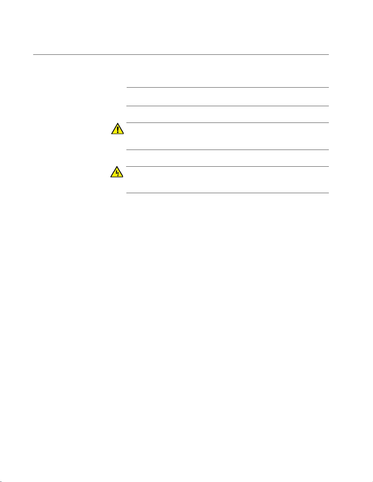
AT-x930-28GPX
AT-x930-28GTX
10/100/1000Base-T Ports
SFP+ Slots
Management
Panel
SFP+ or
Stacking Slots
SFP+ Slots
Management
Panel
SFP+ or
Stacking Slots
10/100/1000Base-T Ports
with PoE+
The front panels of the x930 Series switches are shown in Figure 1 and
Figure 2 on page 22.
x930 Series Installation Guide for Stand-alone Switches
Figure 1. Front Panels of the AT-x930-28GTX and AT-x930-28GPX
Switches
21
Page 22
Chapter 1: Overview
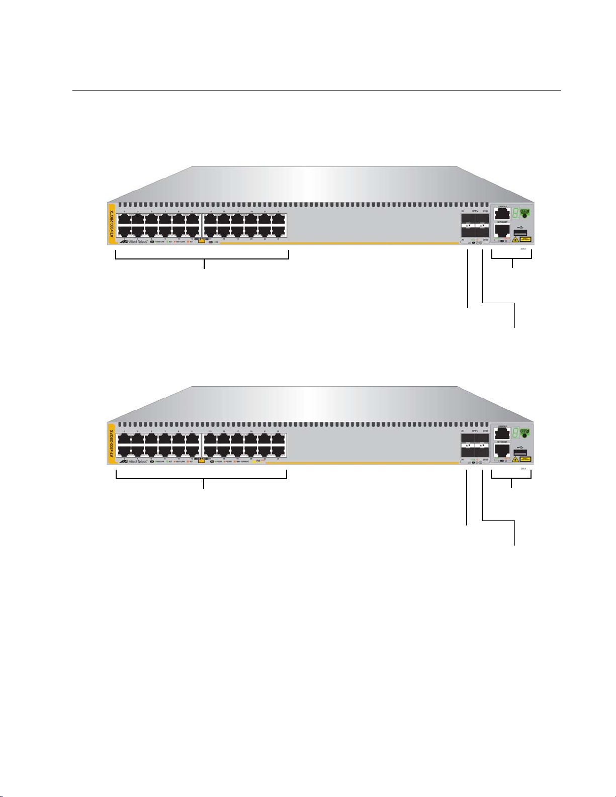
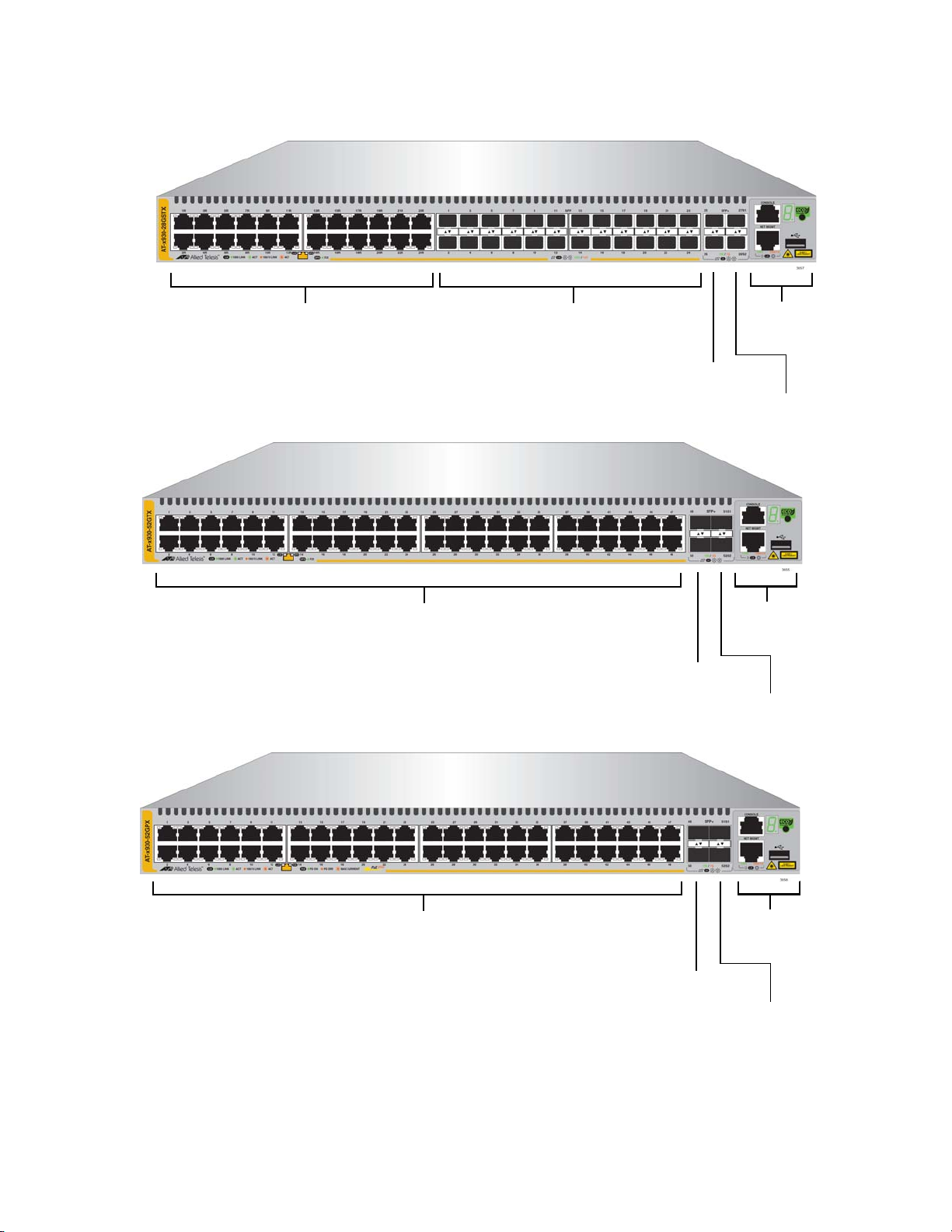
AT-x930-52GPX
AT-x930-52GTX
SFP+ Slots
Management
Panel
SFP+ or
Stacking Slots
10/100/1000Base-T Ports
SFP+ Slots
Management
Panel
SFP+ or
Stacking Slots
10/100/1000Base-T Ports
with PoE+
AT-x930-28GSTX
SFP+ Slots
Management
Panel
SFP+ or
Stacking Slots
10/100/1000Base-T Ports
SFP Slots
22
Figure 2. Front Panels of the AT-x930-28GSTX, AT-x930-52GTX, and AT-
x930-52GPX Switches
Page 23
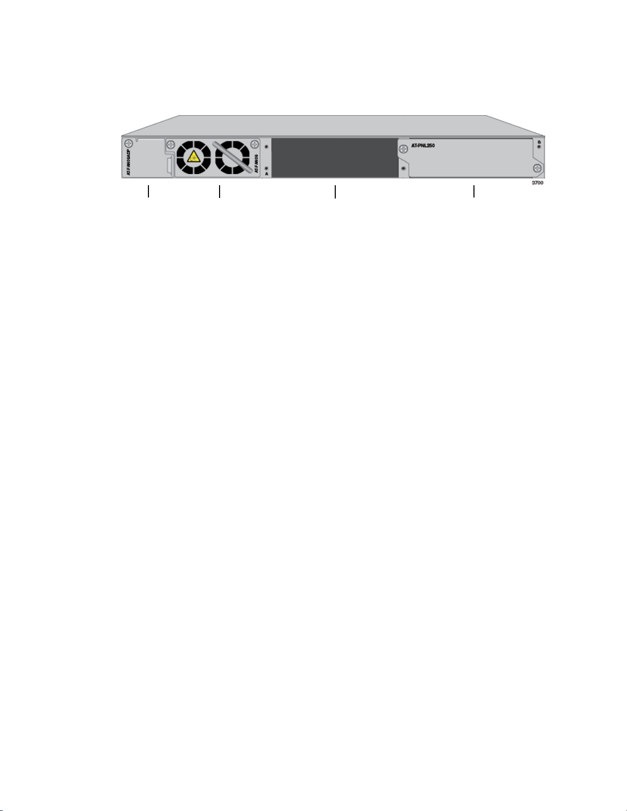
x930 Series Installation Guide for Stand-alone Switches
AT-FAN09
Fan Module
Power Supply Slot B
Power Supply Slot A
AT-FAN09ADP
Module
with AT-PNL250 Blank Panel
Figure 3 shows the back panel. The back panel is the same on all of the
switches.
Figure 3. Back Panel
23
Page 24
Chapter 1: Overview
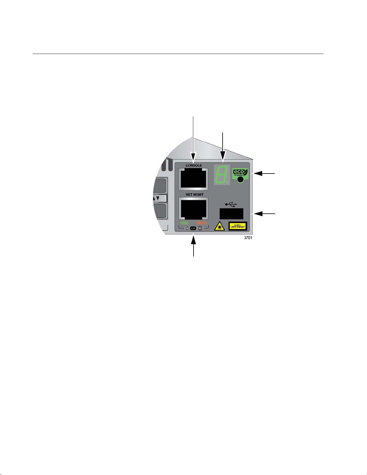
Console
eco-friendly
Button
Switch
Port
ID LED
Management
USB Port
Network Management Port
Management Panel
Figure 4 identifies the components in the management panel on the x930
Series switches.
24
Figure 4. Management Panel
Page 25
Power Supplies
x930 Series Installation Guide for Stand-alone Switches
There are five power supply models for the x930 Series switches. The
models are listed here:
AT-PWR150
AT-PWR250
AT-PWR250-80
AT-PWR800
AT-PWR1200
The top three models are primarily intended for the non-PoE AT-x93028GTX, AT-x930-28GSTX, and AT-x930-52GTX Switches. The bottom
two power supplies are for the PoE AT-x930-28GPX and AT-x930-52GPX
Switches.
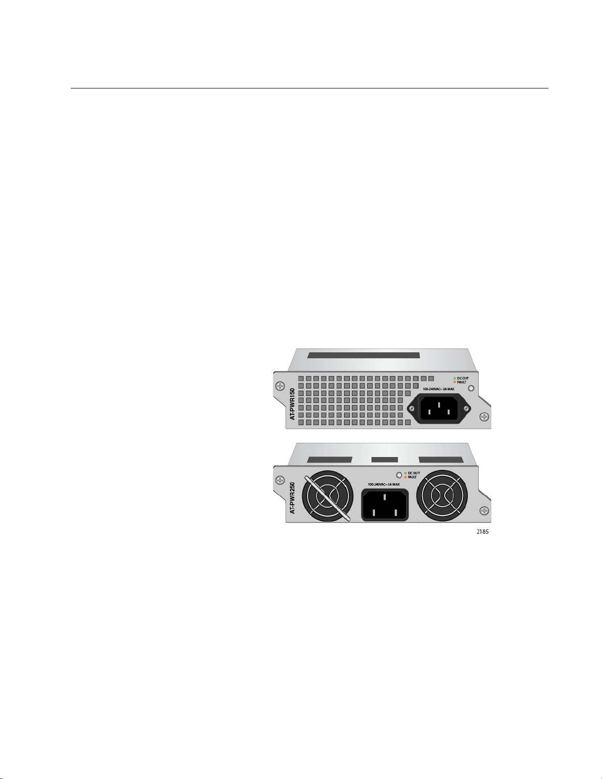
Figure 5 illustrates the AT-PWR150 and AT-PWR250 Power Supplies.
The two power supplies are functionally identical.
Figure 5. AT-PWR150 and AT-PWR250 Power Supplies
The two power supplies are primarily designed for the non-PoE switches
and have these operating characteristics:
The power supplies provide system power, but no PoE power.
A single power supply can power an entire non-PoE switch.
Installing two power supplies in a switch adds power redundancy.
The power supplies are not recommended for the PoE AT-x930-
28GPX and AT-x930-52GPX Switches because they do not have
power for PoE devices. You may install them into PoE switches,
but the switches will not be able to support PoE powered devices.
25
Page 26
Chapter 1: Overview
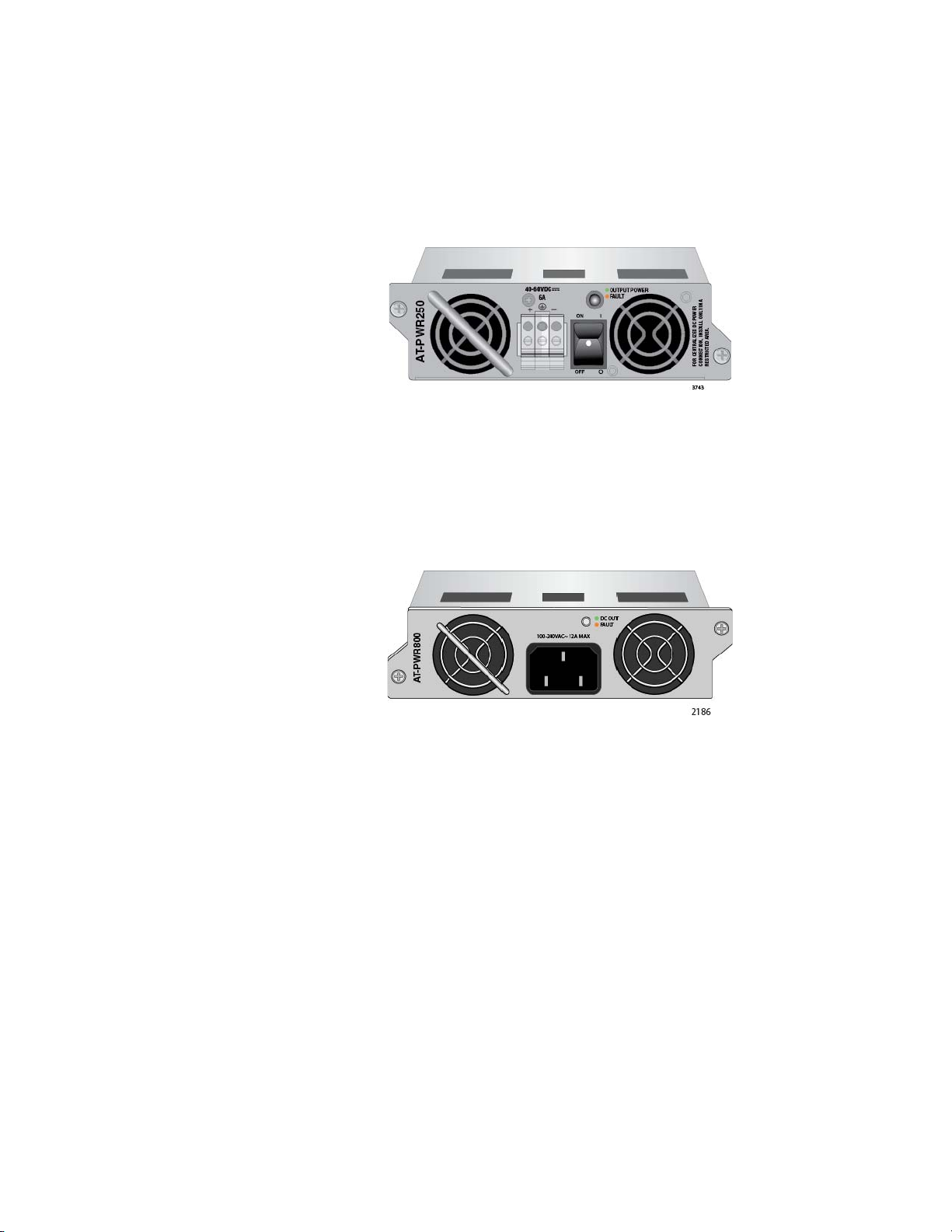
The AT-PWR250-80 DC Power Supply illustrated in Figure 6 has the
same operating characteristics as the AT-PWR150 and AT-PWR250
Power Supplies. It, too, is intended for the non-PoE switches because it
can supply system power, but no PoE power. The only difference is that
this power supply has a DC wiring connector instead of an AC connector,
for DC wiring environments.
Figure 6. AT-PWR250-80 Power Supply
Figure 7 illustrates the AT-PWR800 Power Supply.This power supply is
primarily intended for the PoE AT-x930-28GPX and AT-x930-52GPX
Switches. It provides both system power to the switch as well as up to 380
watts of PoE power for the powered devices connected to the network
ports.
26
Figure 7. AT-PWR800 Power Supply
A PoE switch with one AT-PWR800 Power Supply has the following power
characteristics:
Full system power
380 watts of PoE power
A switch with two AT-PWR800 Power Supplies has these power
characteristics:
Full system power and redundant system power
Either 740 watts of PoE power or 380 watts of active PoE power
and 380 watts of redundant PoE power.
You may install the AT-PWR800 Power Supply in the non-PoE AT-x93028GTX and AT-x930-52GTX Switches. But because the switches do not
support PoE, the power supply will provide system power but no PoE
power.
Page 27

x930 Series Installation Guide for Stand-alone Switches
The AT-PWR1200 Power Supply is shown in Figure 8. It is similar to the
AT-PWR800 Power Supply in that it is intended for the PoE AT-x93028GPX and AT-x930-52GPX Switches because it provides both system
power and power for PoE devices. The difference between them is the
amount of PoE power. The AT-PWR1200 Power Supply can provide up to
740 watts compared to 380 watts for the AT-PWR800 Power Supply.
Figure 8. AT-PWR1200 Power Supply
A PoE switch with one AT-PWR1200 Power Supply has the following
power characteristics:
Full system power
740 watts of power for PoE devices
A switch with two AT-PWR1200 Power Supplies has these power
characteristics:
Full system power and redundant system power
Either 1440 watts of PoE power or 740 watts of active PoE power
and 740 watts of redundant PoE power.
Guidelines Please review the following guidelines concerning power supplies:
The x930 Series Switches do not come with power supplies. The
power supplies must be ordered separately.
If you install two power supplies in the switch, they must both be
the same model. For example, you may install two AT-PWR800
Power Supplies or two AT-PWR1200 Power Supplies in a switch.
You may not install two different power supply models in the
switch.
The non-PoE AT-x930-28GTX AT-x930-28GSTX, and AT-x930-
52GTX Switches require only one power supply for full operations.
Installing a second power supply adds power redundancy, which
protects against interruptions to network operations in the event
one power supply loses power or fails. Power redundancy is
available only when both AC or DC connectors on the switch are
connected to power sources.
27
Page 28
Chapter 1: Overview
Warning
Warning
Note
The PoE AT-x930-28GPX and AT-x930-52GPX Switches also
require only one power supply for network operations, excluding
PoE. The switches can continue to operate even if one power
supply fails or loses power.
The second power supply in the PoE switches either increases the
amount of power for PoE or adds PoE redundancy. For further
information, refer to “Power Budget” on page 33.
The DC wires for the AT-PWR250-80 DC Power Supply should be
routed from a DC load center containing appropriate overcurrent
branch protection for each DC feed, as required by the cognizant
local electrical authority.
Refer to “Technical Specifications” on page 149 for the input voltage
ranges.
Power cord is used as a disconnection device. To de-energize
equipment, disconnect the power cord. E3
This unit might have more than one power cord. To reduce the risk
of electric shock, disconnect all power cords before servicing the
unit. E30
The AT-PWR150, AT-PWR250, AT-PWR800, and AT-PWR1200
Power Supplies are powered on or off by connecting or
disconnecting the power cords. The AT-PWR250-80 Power Supply
is powered on or off with its On/Off power switch or by deactivating
the DC circuit.
28
Page 29

x930 Series Installation Guide for Stand-alone Switches
Note
Note
10/100/1000Base-T Twisted Pair Ports
The twisted pair ports on the switches are described in this section.
Speed The ports can operate at 10, 100, or 1000 Mbps. The speeds may be set
manually using the management software or automatically with AutoNegotiation (IEEE 802.3u), the default setting.
The ports must be set to Auto-Negotiation to function at 1000 Mbps
and are not compatible with devices that are not IEEE 802.3u
compliant.
Duplex Mode The twisted pair ports can operate in either half- or full-duplex mode. The
duplex mode of a port, like port speed, may be set manually using the
management software or automatically with Auto-Negotiation (IEEE
802.3u), the default setting.
Wiring
Configuration
The speed and duplex mode settings of a port may be set independently
of each other. For example, a port may be configured such that its speed
is set manually while its duplex mode is established through AutoNegotiation.
A switch port should not use Auto-Negotiation to set its duplex mode
if it is connected to a network device that does not support AutoNegotiation for 10 or 100 Mbps operation and has a fixed duplex
mode of full-duplex. Otherwise, a duplex-mode mismatch may occur
in which a switch port and a network device operate at different
duplex modes. The duplex modes of switch ports that are connected
to network devices that do not support Auto-Negotiation should be
set manually through the management software.
The wiring configuration of a port operating at 10 or 100 Mbps can be MDI
or MDI-X. The wiring configurations of a switch port and a network device
connected with straight-through twisted pair cabling have to be opposite,
such that one device is using MDI and the other MDI-X. For instance, a
switch port has to be set to MDI-X if it is connected to a network device set
to MDI.
You may set the wiring configurations of the ports manually or let the
switch configure them automatically with auto-MDI/MDI-X (IEEE 802.3abcompliant). This feature enables the switch to automatically negotiate with
network devices to establish their proper settings.
29
Page 30

Chapter 1: Overview
Note
The MDI and MDI-X settings do not apply when ports are operating at
1000 Mbps.
Maximum
Distance
Cable
Requirements
The ports have a maximum operating distance of 100 meters (328 feet).
The cable requirements of the ports are given in Table 2.
Table 2. Twisted Pair Cable for the 10/100/1000Base-T Ports
Cable Type 10Mbps 100Mbps 1000Mbps
Standard TIA/EIA 568-Bcompliant Category 3 shielded
or unshielded cabling with 100
ohm impedance and a
frequency of 16 MHz.
Standard TIA/EIA 568-Acompliant Category 5 or TIA/
EIA 568-B-compliant Enhanced
Category 5 (Cat 5e) shielded or
unshielded cabling with 100
ohm impedance and a
frequency of 100 MHz.
Yes Yes No
Yes Yes Yes
Standard TIA/EIA 568-Bcompliant Category 6 or 6a
shielded cabling.
For the cable requirements for the ports on the AT-x930-28GPX and
AT-x930-52GPX Switches for PoE devices, refer to Table 4 on
page 32.
Yes Yes Yes
Port Pinouts Refer to Table 29 on page 156 and Table 30 on page 156 for the port
pinouts of the 10/100/1000Base-T twisted pair ports.
30
Page 31

Power Over Ethernet
The AT-x930-28GPX and AT-x930-52GPX Switches feature Power over
Ethernet (PoE) on the 10/100/1000Base-T ports. PoE is used to supply
power to network devices over the same twisted pair cables that carry the
network traffic.
The main advantage of PoE is that it can make it easier to install a
network. The selection of a location for a network device is often limited by
whether there is a power source nearby. This often limits equipment
placement or requires the added time and cost of having additional
electrical sources installed. But with PoE, you can install PoE-compatible
devices wherever they are needed without having to worry about whether
there are power sources nearby.
A device that provides PoE to other network devices is referred to as
power sourcing equipment (PSE). The AT-x930-28GPX and AT-x93052GPX Switches act as PSE units by adding DC power to the network
cable, thus functioning as a central power source for other network
devices.
x930 Series Installation Guide for Stand-alone Switches
Devices that receive their power from a PSE are called powered devices
(PD). Examples include wireless access points, IP telephones, webcams,
and even other Ethernet switches.
The switch automatically determines whether or not a device connected to
a port is a powered device. Ports that are connected to network nodes that
are not powered devices (that is, devices that receive their power from
another power source) function as regular Ethernet ports, without PoE.
The PoE feature remains activated on the ports but no power is delivered
to the devices.
PoE Standards The AT-x930-28GPX and AT-x930-52GPX Switches support these PoE
standards:
PoE (IEEE 802.3af): This standard provides up to 15.4 watts at the
switch port to support powered devices that require up to 12.95
watts.
PoE+ (IEEE 802.3at): This standard provides up to 30.0 watts at
the switch port to support powered devices that require up to 25.5
watts.
Powered Device
Classes
Powered devices are grouped into the five classes listed in Table 3 on
page 32. The classes are based on the amount of power the devices
require. The switches support all five classes.
31
Page 32

Chapter 1: Overview
Table 3. IEEE Powered Device Classes
Maximum Power
Class
0 15.4W 0.44W to 12.95W
1 4.0W 0.44W to 3.84W
2 7.0W 3.84W to 6.49W
3 15.4W 6.49W to 12.95W
4 30.0W 12.95W to 25.5W
Output from a Switch
Port
PD Power Range
Cable
Requirements
Table 4. Twisted Pair Cable Requirements for the 10/100/1000Base-T Ports at 10 or 100Mbps
Cable Type
Standard TIA/EIA 568-Bcompliant Category 3 shielded
or unshielded cabling with 100
ohm impedance and a
frequency of 16 MHz.
Standard TIA/EIA 568-Acompliant Category 5 shielded
or unshielded cabling with 100
ohm impedance and a
frequency of 100 MHz.
Standard TIA/EIA 568-Bcompliant Enhanced Category
5 (Cat 5e) shielded or
unshielded cabling with 100
ohm impedance and a
frequency of 100 MHz.
The cable requirements for ports operating at 10 or 100Mbps are given in
Table 4.
10Mbps 100Mbps
Non-
PoE
Yes Yes No Yes Yes No
Yes Yes No Yes Yes No
Yes Yes Yes Yes Yes Yes
PoE PoE+
Non-
PoE
PoE PoE+
32
Standard TIA/EIA 568-Bcompliant Category 6 or 6a
shielded cabling.
Yes Yes Yes Yes Yes Yes
Page 33

x930 Series Installation Guide for Stand-alone Switches
The cable requirements for ports operating at 1000Mbps are given in
Table 5.
Table 5. Twisted Pair Cable Requirements for the 10/100/1000Base-T
Ports at 1000Mbps
1000Mbps
Cable Type
Standard TIA/EIA 568-B-compliant
Non-
PoE
PoE PoE+
No No No
Category 3 shielded or unshielded
cabling with 100 ohm impedance and a
frequency of 16 MHz.
Standard TIA/EIA 568-A-compliant
Yes Yes No
Category 5 shielded or unshielded
cabling with 100 ohm impedance and a
frequency of 100 MHz.
Standard TIA/EIA 568-B-compliant
Yes Yes Yes
Enhanced Category 5 (Cat 5e) shielded
or unshielded cabling with 100 ohm
impedance and a frequency of 100 MHz.
Standard TIA/EIA 568-B-compliant
Yes Yes Yes
Category 6 or 6a shielded cabling.
Power Budget The power budget is the maximum amount of power the switch can supply
to the powered devices on its ports. The higher the budget, the more PoE
devices the switch can support at one time.
The power budgets of the AT-x930-28GPX and AT-x930-52GPX Switches
depend on several factors. The first is the power supply model. The po wer
budgets of the five power supplies are listed in Table 6.
Table 6. Power Supply Budgets of the Power Supplies
Power Supply Power Budget for PoE Devices
AT-PWR150 0 watts
AT-PWR250 0 watts
AT-PWR250-80 0 watts
AT-PWR800 380 watts
AT-PWR1200 740 watts
33
Page 34

Chapter 1: Overview
Note
The AT-PWR250 and AT-PWR250-80 Power Supplies are intended
for the non-PoE AT-x930-28GTX, AT-x930-28GSTX, and AT-x93052GTX Switches. They are not intended for the AT-x930-28GPX
and AT-x930-52GPX Switches because they do not provide power
for PoE + devices. You may install them in the PoE+ switches, but
the switches will not support PoE devices.
Another factor that determines the power budget of the switch is the
number of PoE power supplies in the device. The power budget of a PoE
switch that has only one PoE power supply is equal to the budget of the
power supply. For example, a switch that has one AT-PWR1200 Power
Supply has a power budget of 740W for powered devices.
A PoE switch with two AT-PWR800 or AT-PWR1200 Power Supplies has
either redundant PoE power or nearly double the power budget. This is
controlled by the power boost feature, which has a status of either enabled
or disabled. When the power boost feature is enabled, a PoE switch with
two power supplies actively uses the PoE power from both supplies to
increase its available power budget. When the feature is disabled, the
switch uses the PoE power of only one of its power supplies and keeps the
other in reserve in case the primary power supply should fail or lose
power.
As an example, assume that a PoE switch has one AT-PWR1200 Power
Supply, which has a power budget of 740W for powered devices. Thus,
the switch would have a total power budget of 740W. Now assume the
switch has two AT-PWR1200 Power Supplies. When the power boost
mode is enabled, the switch uses the PoE power from both supplies, for a
total power budget of 1440W. When the power boost mode is disabled,
the switch has an active PoE power of 740W and a redundant budget of
the same amount. The switch activates the redundant power budget only if
the power supply providing the active power budget fails or loses power.
Table 7 lists the power budgets for the switch with one or two AT-PWR800
Power Supplies and the power boost mode.
Table 7. Power Budgets of the AT-PWR800 Power Supply
Number of
Power
Supplies in the
State of Power
Boost
Power Budget
of the Switch
Redundant
Power
Switch
One NA 380 watts 0 watts
Two Enabled 740 watts 0 watts
Two Disabled 380 watts 380 watts
34
Page 35

x930 Series Installation Guide for Stand-alone Switches
Table 8 lists the power budgets for the switch with one or two ATPWR1200 Power Supplies and the power boost mode.
Table 8. Power Budgets of the AT-PWR1200 Power Supply
Number of
Power
Supplies in the
State of Power
Boost
Power Budget
of the Switch
Redundant
Power
Switch
One NA 740 watts 0 watts
Two Enabled 1440 watts 0 watts
Two Disabled 740 watts 740 watts
The maximum number of PoE devices the switch can support at one time
is determined by its power budget and the power requirements of the
devices. The switch can supply power to all of the devices as long as the
their total power requirements is less than its power budget. If the switch
determines that the power requirements of the devices exceed its power
budget, it denies power to one or more ports using a mechanism referred
to as port prioritization.
Port
Prioritization
To determine whether the power requirements of the PoE devices you
plan to connect to the switch exceed its power budget, refer to their
documentation for their power requirements and add the requirements
together. The switch should be able to power all of the devices
simultaneously as long as the total is below its power budget. If the total
exceeds the available power budget, you should consider reducing the
number of PoE devices so that all of the devices receive power.
Otherwise, the switch powers a subset of the devices, based on port
prioritization.
The switch can handle different power requirements on different ports.
This enables you to connect different classes of PoE equipment to the
ports on the switch.
If the power requirements of the powered devices exceed the switch’s
power budget, the switch denies power to some ports based on a system
called port prioritization. You may use this mechanism to ensure that
powered devices critical to the operations of your network are given
preferential treatment by the switch in the distribution of power should the
demands of the devices exceed the available capacity.
There are three priority levels:
Critical
High
Low
35
Page 36

Chapter 1: Overview
Ports set to the Critical level, the highest priority level, are guaranteed
power before any of the ports assigned to the other two priority levels.
Ports assigned to the other priority levels receive power only if all the
Critical ports are receiving power. Ports that are connected to your most
critical powered devices should be assigned to this level. If there is not
enough power to support all the ports set to the Critical priority level,
power is provided to the ports based on port number, in ascending order.
The High level is the second highest level. Ports set to this level receive
power only if all the ports set to the Critical level are already receiving
power. If there is not enough power to support all of the ports set to the
High priority level, power is provided to the ports based on port number, in
ascending order.
The lowest priority level is Low. This is the default setting. Ports set to this
level only receive power if all of the ports assigned to the other two levels
are already receiving power. As with the other levels, if there is not enough
power to support all of the ports set to the Low priority level, power is
provided to the ports based on port number, in ascending order.
Wiring
Implementation
Power allocation is dynamic. Ports supplying power to powered devices
may cease power transmission if the switch’s power budget is at
maximum usage and new powered devices, connected to ports with
higher priorities, become active.
The IEEE 802.3af standard defines two methods for the delivery of DC
power over twisted pair cable by a switch to the powered devices. These
methods, known as modes A and B, identify the wires within the cable that
carry the DC power from the switch to a powered device.
Twisted pair cabling typically consists of eight wires. With 10Base-T and
100Base-TX devices, the wires connected to pins 1, 2, 3, and 6 on the RJ45 connectors carry the network traffic while the wires connected to pins 4,
5, 7, and 8 are unused. With 1000Base-T devices, all eight wires are used
to carry network data.
It takes four wires to deliver DC power to a powered device. With Mode A,
the power is delivered on pins 1, 2, 3, and 6. These are the same pins in
10Base-T and 100Base-TX devices that carry the network data. With
mode B, the power is provided over the spare wires.
The ports on the AT-x930-28GPX and AT-x930-52GPX Switches deliver
the power using pins 1, 2, 3, and 6, which corresponds to mode A in the
IEEE 802.3af standard. Powered devices that comply with the IEEE
802.3af standard are required to support both power delivery methods.
Legacy devices that do not comply with the standard will work with the
switch if they are powered on pins 1, 2, 3, and 6.
36
Page 37

SFP Slots
x930 Series Installation Guide for Stand-alone Switches
The twenty four SFP slots on the AT-x930-28GSTX Switch support the
following types of transceivers:
100Base-FX, 1000Base-T, and 1000Base-SX/LX SFP transceivers
Single-port BiDi 100Base-FX and 1000Base-LX SFP transceivers
1000Base-ZX SFP transceivers
The slots are paired with the twenty four 10/100/1000Base-T twisted pair
ports. SFP slot 1 is paired with twisted pair port 1R, slot 2 with twisted pair
port 2R, and so on. Only one slot or port in a pair can be active at a time.
For example, if you install an SFP transceiver in slot 3 and connect it to an
active network device, the switch deactivates twisted pair port 3R.
Please review the following guidelines for using the SFP slots on the ATx930-28GSTX Switch:
Each SFP slot is paired with a twisted pair port.
You may not change the pairings of the ports and slots.
Only one port or slot in a pair can be active at a time.
The twisted pair port is the default active port of a pair.
An SFP slot automatically becomes active when you install and
connect an SFP transceiver to an active network device.
The switch automatically reactivates the twisted pair port of a pair
when the transceiver in the corresponding SFP slot loses its link to
a remote network device. For example, the switch reactivates
twisted pair port 4R if you disconnect the fiber optic cable from a
transceiver in slot 4.
The letter “R” in the numbering of the twisted pair ports on the front
of the switch refers to the “redundant” function of the ports. The
twisted pair ports are only available when their corresponding SFP
slots are empty or the SFP transceivers have not established links
with network devices.
37
Page 38

Chapter 1: Overview
Note
Note
Note
Note
SFP+ Slots
The four SFP+ slots on the switches support the following types of SFP
1000Mbps and SFP+ 10Gbps transceivers:
1000Base-SX/LX SFP transceivers
Single-port BiDi 1000Base-LX SFP transceivers
1000Base-ZX SFP transceivers
10Gbps, 10GBase-SR/LR fiber optic transceivers
10Gbps AT-SP10TW direct connect twinax cables with SFP+
transceiver-style connectors
You may use the slots and transceivers to connect switches to other
network devices over large distances, build high-speed backbone
networks between network devices, or connect high-speed devices, such
as servers, to your network.
The switches support a variety of short or long distance SFP or SFP+
modules. For a list of supported modules, contact your Allied Telesis
representative or visit our web site.
The SFP+ slots do not support 100Mbps 100Base-FX transceivers.
The slots support full-duplex mode only.They do not support halfduplex mode.
SFP and SFP+ transceivers must be purchased separately.
SFP+ slots 27/S1 and 28/S2 on the AT-x930-28GTX, AT-x93028GSTX, and AT-x930-28GPX Switches and slots 51/S1 and 52/S2
on the AT-x930-52GTX and AT-x930-52GPX Switches are initially
configured as stacking slots for the VCStack feature. If you intend to
use the switch as a stand-alone unit, you must disable the VCStack
feature before you can use the slots with standard SFP or SFP+
transceivers. The configuration instructions are provided later in this
guide, in Chapter 10, “Configuring the Switch for Stand-alone
Operation” on page 125.
38
Page 39

Stacking S1 and S2 SFP+ Slots
Note
Note
As explained in the previous section, you may use the four SFP+ slots on
the front panel of the switch with SFP 1000Mbps or SFP+ 10Gbps
transceivers to add high speed links from the switch to other network
devices. However, SFP+ slots 27/S1 and 28/S2 on the 28-port switches
and slots 51/S1 and 52/S2 on the 52-port switches have an additional
function. They can also be used with SFP+ transceivers and the VCStack
feature to build a stack of up to eight switches. The switches of a VCStack
act as a single virtual unit. They synchronize their actions so that switching
operations, like spanning tree protocols, virtual LANs, and static port
trunks, span across all of the units and ports. The two main advantages of
stacks are listed here:
You can manage multiple units simultaneously, which can simplify
network management.
You have more flexibility in how you configure some of the
features. For instance, a static port trunk on a stand-alone switch
has to consist of ports from the same switch. In contrast, a static
trunk on a stack may consist of ports from different switches in the
same stack.
x930 Series Installation Guide for Stand-alone Switches
SFP+ slots 27/S1 and 28/S2 on the 28-port switches and slots 51/S1
and 52/S2 on the 48-port switches are initially configured as stacking
slots for the VCStack feature. If you intend to use the switch as a
stand-alone unit, you must disable the VCStack feature before you
can use the slots with standard SFP or SFP+ transceivers. The
configuration instructions are provided later in this guide, in Chapter
10, “Configuring the Switch for Stand-alone Operation” on page 125.
This guide explains how to install the devices as stand-alone units.
For instructions on how to install the switches in a VCStack with the
S1 and S2 slots, refer to the x930 Series Installation Guide for
Virtual Chassis Stacking.
39
Page 40

Chapter 1: Overview
Ethernet Management Port (NET MGMT)
The NET MGMT port in the management panel of the switch is a separate
routed eth0 interface. The interface is not part of the switching matrix of
the Ethernet line cards, but the CPU on the controller card can route traffic
in or out of the port from the line cards.
Here are the guidelines to using the port:
The port should only be used for initial configuration and
maintenance access to the chassis.
The NET MGMT port has a standard RJ-45 8-pin connector and
operates at 10, 100, or 1000 Mbps in either half- or full-duplex
mode.
The cable requirements for the port are the same as for the 10/
100/1000-T ports, listed in Table 2 on page 30. For the port
pinouts, refer to “RJ-45 Twisted Pair Port Pinouts” on page 156.
NET MGMT
LEDs
The default setting for the port is Auto-Negotiation, which sets the
speed and duplex mode automatically. You may disable AutoNegotiation and configure the port manually.
The wiring configuration of the NET MGMT port is set
automatically with automatic MDIX detection. You may disable
automatic MDIX detection and set the wiring configuration
manually.
The port is referred to as eth0 in the management software.
For instructions on how to configure the NET MGMT port, refer to the
Software Reference for x930 Series Switches.
The Network Management (NET MGMT) port on the switch has two
Status LEDs, described in Table 9.
Table 9. NET MGMT Port LED
LED State Description
Left
Solid Green The port has a valid 1000 Mbps link.
LED
Flashing
Green
The port is transmitting or receiving data at
1000 Mbps.
40
Right
LED
Solid Amber The port has a valid 10 or 100 Mbps link.
Flashing
Amber
The port is transmitting or receiving data at
10 or 100 Mbps.
Page 41

eco-friendly Button
Note
x930 Series Installation Guide for Stand-alone Switches
The eco-friendly button on the front panel of the switch is used to toggle
the port LEDs on or off. You might turn off the LEDs to conserve electricity
when you are not monitoring the device. You can also toggle the LEDs
with the ECOFRIENDLY LED and NO ECOFRIENDLY LED commands in
the Global Configuration mode of the command line interface. The switch
is said to be operating in a low power mode when the LEDs are turned off.
Operating the switch in the low power mode with the LEDs turned off does
not interfere with the network operations of the device.
The management software on the switch has a command that blinks the
LEDs so that you can quickly and easily identify a specific unit among the
devices in an equipment rack. It is the FINDME command. The command
works on the switch even if you turned off the LEDs with the eco-friendly
button or NO ECOFRIENDLY LED command.
The Switch ID LED is always on, but it displays different information
depending on whether the LEDs are on or off. When the LEDs are on, the
ID LED displays the ID number of the switch. When the switch is operating
in the low power mode with the LEDs off, the ID LED indicat es whether the
switch is a stand-alone unit or the master or member switch of a VCStack,
as detailed in Figure 15 on page 49.
Before checking or troubleshooting the network connections to the
ports on the switch, you should always check to be sure that the
LEDs are on by either pressing the eco-friendly button or issuing the
ECOFRIENDLY LED and NO ECOFRIENDLY LED commands in
the Global Configuration mode of the command line interface.
41
Page 42

Chapter 1: Overview
Link/Activity
LED
Duplex Mode
LED
Duplex Mode
LED
Link/Activity
LED
LEDs
Here are descriptions of the LEDs.
LEDs for the
Twisted Pair
Ports
The twisted pair ports on the AT-x930-28GTX, AT-x930-28GSTX, and ATx930-52GTX Switches have two LEDs that display link, activity and duplex
mode information. The LEDs are shown in Figure 9.
Figure 9. LEDs for the 10/100/1000Base-T Ports on the AT-x930-28GTX,
AT-x930-28GSTX, and AT-x930-52GTX Switches
42
The LEDs are described in Table 10 on page 43.
Page 43

x930 Series Installation Guide for Stand-alone Switches
Note
Table 10. LEDs on the 10/100/1000Base-T Ports on the AT-x930-28GTX,
AT-x930-28GSTX, and AT-x930-52GTX Switches
LED State Description
Solid Green A port has established a 1000 Mbps link to
a network device.
Link/
Activity
LED
Flashing
Green
Solid Amber A port has established a 10 or 100 Mbps
A port is transmitting or receiving data at
1000 Mbps.
link to a network device.
Flashing
Amber
A port is transmitting or receiving data at 10
or 100 Mbps.
Off A port has not established a link with
another network device or the LEDs are
turned off. To turn on the LEDs, use the
eco-friendly button.
Duplex
Green A port is operating in full duplex mode.
Mode
LED
Amber A port is operating in half-duplex mode at 10
or 100 Mbps. (Half-duplex mode does not
apply to 1000 Mbps operation.)
Flashing
Amber
Collisions are occurring on a port operating
at 10 or 100 Mbps.
The twisted pair ports on the AT-x930-28GPX and AT-x930-52GPX
Switches have two LEDs that display link, activity and PoE information.
The LEDs are shown in Figure 10 on page 44.
You can view the duplex mode information for the ports on the ATx930-28GPX and AT-x930-52GPX Switches with the management
software.
43
Page 44

Chapter 1: Overview
Link/Activity
LED
PoE
LED
PoE
LED
Link/Activity
LED
Figure 10. LEDs for the 10/100/1000Base-T Ports on the AT-x930-28GPX
and AT-x930-52GPX Switches
The LEDs are described in Table 11.
Table 11. LEDs on the 10/100/1000Base-T Ports on the AT-x930-28GPX
and AT-x930-52GPX Switches
LED State Description
Solid Green A port has established a 1000 Mbps link to
a network device.
Link/
Activity
LED
Flashing
Green
Solid Amber A port has established a 10 or 100 Mbps
Flashing
Amber
A port is transmitting or receiving data at
1000 Mbps.
link to a network device.
A port is transmitting or receiving data at 10
or 100 Mbps.
Off A port has not established a link with
another network device or the LEDs are
turned off. To turn on the LEDs, use the
eco-friendly button.
44
Page 45

x930 Series Installation Guide for Stand-alone Switches
SFP Slot LEDs
Table 11. LEDs on the 10/100/1000Base-T Ports on the AT-x930-28GPX
and AT-x930-52GPX Switches (Continued)
LED State Description
PoE Green The switch detects a powered device (PD)
on the port and is delivering power to it.
Solid Amber The switch has shut down PoE+ on the port
because of a fault condition.
LEDs for the SFP
Slots
Flashing
Amber
The switch detects a PD on the port but is
not delivering power to it because it has
reached its maximum power budget.
Off This LED state can result from the following
conditions:
The port is not connected to a PD.
The PD is powered off.
The port is disabled in the
management software.
PoE is disabled on the port.
The LEDs on the Ethernet line cards
are turned off. To turn on the LEDs,
use the eco-friendly button.
The LEDs for the twenty four SFP slots on the AT-x930-28GSTX Switch
are located between the slots. Refer to Figure 11. Each SFP slot has one
LED. The left-hand LED is for the top slot and the right-hand LED is for the
bottom slot.
Figure 11. SFP Slot LEDs
45
Page 46

Chapter 1: Overview
SFP Slot LEDs
The possible states of the LED for the SFP slots are described in
Table 12.
Table 12. SFP Slot LEDs on the AT-x930-28GSTX Switch
LED State Description
Solid green The SFP transceiver in the slot has
established a link at 1000 Mbps to a
network device.
LEDs for the
SFP+ Slots
Flashing
green
Link/Activity
The LEDs for the SFP+ slots are located between the slots, as shown in
Figure 12. Each SFP+ slot has one LED. The left-hand LED is for the top
slot and the right-hand LED is for the bottom slot.
Solid amber The SFP transceiver in the slot has
Flashing
amber
Off The slot is empty, the SFP transceiver
The SFP transceiver is receiving or
transmitting packets to a network device
at 1000 Mbps.
established a link at 100 Mbps to a
network device.
The SFP transceiver is receiving or
transmitting packets to a network device
at 100 Mbps.
has not established a link to a network
device, or the LEDs are turned off. To turn
on the LEDs, use the eco-friendly button.
46
Figure 12. SFP+ Slot LEDs
The LEDs are described in Table 13 on page 47.
Page 47

x930 Series Installation Guide for Stand-alone Switches
Table 13. SFP+ Slot LEDs
LED State Description
Solid green The SFP+ transceiver in the slot has
established a link at 10 Gbps to a network
device.
LEDs for the
Stacking Slots
Flashing
green
Link/Activity
SFP+ slots 27/S1 and 28/S2 on the 28-port switches and slots 51/! and 52/
S2 on the 52-port switches may be used as stacking slots to build a
VCStack of up to eight switches. For background information, refer to the
x930 Series Installation Guide for Virtual Chassis Stacking. Table 14
defines the LED states when the slots are used to build a stack of
switches.
Solid amber The SFP transceiver in the slot has
Flashing
amber
Off The slot is empty, the SFP or SFP+
The SFP+ transceiver is receiving or
transmitting packets to a network device
at 10 Gbps.
established a link at 1000 Mbps to a
network device.
The SFP transceiver is receiving or
transmitting packets to a network device
at 1000 Mbps.
transceiver has not established a link to a
network device, or the LEDs are turned
off. To turn on the LEDs, use the ecofriendly button.
Table 14. Stacking Slot LEDs
LED State Description
Link/Activity Off The slot is empty, the stacking transceiver
has not established a link to a network
device, or the LEDs are turned off. To turn
on the LEDs, use the eco-friendly button.
Solid green The stacking transceiver has established
a 10 Gbps link to another switch in the
stack.
Flashing
green
The stacking transceiver is receiving or
transmitting packets.
47
Page 48

Chapter 1: Overview
Switch ID LED
The switch is booting up.
The switch has encountered a fault condition.
The switch is operating as a stand-alone unit, with the ID
number 0.
The switch has an ID number of 1 to 8 as part of a VCStack.
The dot in the lower right corner flashes when the switch
accesses USB memory.
Switch ID LED The Switch ID LED, shown in Figure 13 on page 48, displays the ID
number of the switch. A stand-alone switch has the ID number 0. Switches
in a VCStack have the numbers 1 to 8. Chapter 9, “Powering On the
Switch” on page 115 has the procedure for verifying and, if necessary,
changing the ID number of the switch.
The states of the LED when the switch is not operating in the low power
mode are shown in Figure 14.
Figure 13. Switch ID LED
48
The switch displays the letter “F” for fault on the ID LED if it detects one of
the following problems:
A cooling fan has failed.
Figure 14. Switch ID LED
Page 49

x930 Series Installation Guide for Stand-alone Switches
Note
The switch is the master switch of a VCStack.
The switch is operating as a stand-alone unit.
The switch is a member switch of a VCStack.
The internal temperature of the switch has exceeded the normal
operating range and the switch may shut down.
You can use the SHOW SYSTEM ENVIRONMENT command in the
command line interface to identify the source of the problem.
The states of the LED when the switch is operating in the low power mode
are shown in Figure 15.
Figure 15. Switch ID LEDs in the Low Power Mode
49
Page 50

Chapter 1: Overview
USB Port
The management panel has a USB port. You may use the port to store
configuration files on flash drives or to restore configuration files to
switches whose settings have been lost or corrupted, or to quickly
configure replacement units. You may also use the port and flash drives to
update the management firmware on the switch.
The port is USB2.0 compatible.
50
Page 51

Console Port
Note
x930 Series Installation Guide for Stand-alone Switches
You use the Console port to manage the switch and configure its features
and parameter settings. This type of management uses serial RS-232 and
is commonly referred to as local management because it is not conducted
over your network. To perform local management, you must be at the
location of the switch and use the management cable included with the
device.
To establish a local management session with the switch, you have to
connect a terminal or a personal computer with a terminal emulation
program to the Console port, which has an RJ-45 style (8P8C) connector,
using the provided management cable. The cable has RJ-45 style (8P8C)
and DB-9 (D-sub 9-pin) connectors.
The Console port is set to the following specifications:
Default baud rate: 9600 bps (Range is 9600 to 115200 bps)
Data bits: 8
Parity: None
Stop bits: 1
Flow control: None
These settings are for a DEC VT100 or ANSI terminal, or an
equivalent terminal emulation program.
51
Page 52

Chapter 1: Overview
Optional Cards
The switches have two optional cards:
AT-StackQS Card AT-x9EM/XT4 Card
AT-StackQS
Card
This card is used to build a VCStack of up to eight switches. The card has
two slots for transceivers. The transceivers are used to build the trunk that
connects the switches of a stack together. The trunk has a speed of
160Gbps. The card is shown in Figure 16.
Figure 16. Optional AT-StackQS Card
The cabling options for the card are provided in the x930 Series
Installation Guide for Virtual Chassis Stacking.
52
Each transceiver slot has one LED. The LED states are defined in
Table 15.
Table 15. AT-StackQS Card LEDs
LED State Description
L/A (Link/
Activity)
Off The port is not connected to another
network device, the device is not powered
on, or the LEDs are turned off. To turn on
the LEDs, use the eco-friendly button.
Solid green The port has established a 10Gbps link to
network device.
Flashing
green
The port is transmitting or receiving
network packets.
Page 53

x930 Series Installation Guide for Stand-alone Switches
Note
For installation instructions for the card and VCStack, refer to x930 Series
Installation Guide for Virtual Chassis Stacking.
AT-x9EM/XT4
Card
This card adds four additional networking ports to the switch, The ports
can operate at either 1Gbps (1000Base-T) or 10Gbps (10Base-T) and
have RJ-45 connectors for twisted pair cables. The card is shown in
Figure 17.
Figure 17. Optional AT-x9EM/XT4 Card
The card requires version 5.4.5-2 or later of the management
software. The instructions in “Verifying Support for Hardware
Options” on page 132 explain how to determine the version number
of the software on the switch.
The cable requirements for the ports are given in Table 16.
Table 16. Twisted Pair Cable for the AT-x9EM/XT4 Card
Port Speed Cable Type
1Gbps Standard TIA/EIA 568-A-
compliant Category 5 or
TIA/EIA 568-B-compliant
Enhanced Category 5 (Cat
5e) shielded or unshielded
cabling
10Gbps Standard TIA/EIA-568-C.1
compliant Category 6a (Cat
6a) shielded or unshielded
cabling
Operating Distance
100 m (328 ft)
100 m (328 ft)
Maximum
53
Page 54

Chapter 1: Overview
Each port has one LED. The states of the LED are defined in Table 17 on
page 54.
Table 17. AT-x9EM/XT4 Card LEDs
LED State Description
L/A (Link/
Activity)
Off The port is not connected to another
network device, the device is not powered
on, or the LEDs are turned off. To turn on
the LEDs, use the eco-friendly button.
Solid green The port has established a 10Gbps link to
a network device.
Flashing
green
The port is transmitting or receiving
network traffic at 10Gbps.
Solid amber The port has established a 1Gbps link to a
network device.
Flashing
amber
The port is transmitting or receiving
network traffic at 1Gbps.
You can install only one AT-x9EM/XT4 Card in the switch. It replaces the
AT-FAN09ADP Module in the back panel. The installation instructions are
provided in Chapter 4, “Installing the AT-x9EM/XT4 Card” on page 75.
54
Page 55

Chapter 2
Beginning the Installation
The chapter contains the following sections:
“Reviewing Safety Precautions” on page 56
“Choosing a Site for the Switch” on page 61
“Unpacking the Switch” on page 62
55
Page 56

Chapter 2: Beginning the Installation
Note
Warning
Warning
Warning
Warning
Warning
Warning
Reviewing Safety Precautions
Please review the following safety precautions before beginning the
installation procedure.
Safety statements that have the symbol are translated into
multiple languages in the T ranslated Safety S t atements document at
www.alliedtelesis.com/support.
Class 1 Laser product. L1
Laser Radiation.
Class 1M Laser product.
Do not stare into the laser beam. L2
Do not look directly at the fiber optic ends or inspect the cable ends
with an optical lens. L6
To prevent electric shock, do not remove the cover. No userserviceable parts inside. This unit contains hazardous voltages and
should only be opened by a trained and qualified technician. To
avoid the possibility of electric shock, disconnect electric power to
the product before connecting or disconnecting the LAN cables.
E1
Do not work on equipment or cables during periods of lightning
activity. E2
56
Page 57

x930 Series Installation Guide for Stand-alone Switches
Warning
Warning
Note
Caution
Warning
Note
Warning
Warning
Power cord is used as a disconnection device. To de-energize
equipment, disconnect the power cord. E3
Class I Equipment. This equipment must be earthed. The power
plug must be connected to a properly wired earth ground socket
outlet. An improperly wired socket outlet could place hazardous
voltages on accessible metal parts. E4
Pluggable Equipment. The socket outlet shall be installed near the
equipment and shall be easily accessible. E5
Air vents must not be blocked and must have free access to the
room ambient air for cooling. E6
Operating Temperatures. This product is designed for a maximum
ambient temperature of 45° degrees C. E52
All Countries: Install product in accordance with local and National
Electrical Codes. E8
When installing this equipment, always ensure that the frame ground
connection is installed first and disconnected last. E11
Only trained and qualified personnel are allowed to install or replace
this equipment. E14
57
Page 58

Chapter 2: Beginning the Installation
Caution
Caution
Warning
Warning
Note
Warning
Circuit Overloading: Consideration should be given to the
connection of the equipment to the supply circuit and the effect that
overloading of circuits might have on overcurrent protection and
supply wiring. Appropriate consideration of equipment nameplate
ratings should be used when addressing this concern. E21
Risk of explosion if battery is replaced by an incorrect type. Replace
only with the same or equivalent type recommended by the
manufacturer. Dispose of used batteries according to the
manufacturer’s instructions.
Attention: Le remplacement de la batterie par une batterie de type
incorrect peut provoquer un danger d’explosion. La remplacer
uniquement par une batterie du même type ou de type équivalent
recommandée par le constructeur. Les batteries doivent être
éliminées conformément aux instructions du constructeur. E22
Mounting of the equipment in the rack should be such that a
hazardous condition is not created due to uneven mechanical
loading. E25
The chassis may be heavy and awkward to lift. Allied Telesis
recommends that you get assistance when mounting the chassis in
an equipment rack. E28
Use dedicated power circuits or power conditioners to supply
reliable electrical power to the device. E27
This unit might have more than one power cord. To reduce the risk
of electric shock, disconnect all power cords before servicing the
unit. E30
58
Page 59

x930 Series Installation Guide for Stand-alone Switches
Note
Caution
Warning
Warning
Warning
Caution
Warning
If installed in a closed or multi-unit rack assembly, the operating
ambient temperature of the rack environment may be greater than
the room ambient temperature. Therefore, consideration should be
given to installing the equipment in an environment compatible with
the manufacturer’s maximum rated ambient temperature (Tmra).
E35
Installation of the equipment in a rack should be such that the
amount of air flow required for safe operation of the equipment is not
compromised. E36
Reliable earthing of rack-mounted equipment should be maintained.
Particular attention should be given to supply connections other than
direct connections to the branch circuits (e.g., use of power strips).
E37
To reduce the risk of electric shock, the PoE ports on this product
must not connect to cabling that is routed outside the building where
this device is located. E40
This product may have multiple AC power cords installed. To deenergize this equipment, disconnect all power cords from the device.
E41
An Energy Hazard exists inside this equipment. Do not insert hands
or tools into open chassis slots or plugs. E44
This equipment shall be installed in a Restricted Access location.
E45
59
Page 60

Chapter 2: Beginning the Installation
Caution
Warning
The unit does not contain serviceable components. Please return
damaged units for servicing. E42
The temperature of an operational SFP or SFP+ transceiver may
exceed 70° C (158° F). Exercise caution when removing or handling
a transceiver with unprotected hands. E43
60
Page 61

Choosing a Site for the Switch
Warning
Observe these requirements when planning the installation of the switch.
If you plan to install the switch in an equipment rack, check to be
sure that the rack is safely secured so that it will not tip over.
Devices in a rack should be installed starting at the bottom, with
the heavier devices near the bottom of the rack.
If you plan to install the switch on a table, check to be sure that the
table is level and stable.
The power outlet should be located near the switch and be easily
accessible.
The site should allow for easy access to the ports on the front of
the switch, so that you can easily connect and disconnect cables,
and view the port LEDs.
The site should allow for adequate air flow around the unit and
through the cooling vents on the front and rear panels. (The
ventilation direction in units that have a cooling fan is from front to
back, with the fan on the back panel drawing the air out of the unit.)
x930 Series Installation Guide for Stand-alone Switches
The site should not expose the switch to moisture or water.
The site should be a dust-free environment.
The site should include dedicated power circuits or power
conditioners to supply reliable electrical power to the network
devices.
Do not install the switch in a wiring or utility box because it will
overheat and fail from inadequate airflow.
Switches should not be stacked on a table or desktop because that
could present a personal safety hazard if you need to move or
replace switches. E91
61
Page 62

Chapter 2: Beginning the Installation
Four equipment rack or wall
mounting brackets
One 2 m (6.6 ft) local management
cable with RJ-45 (8P8C) and DB-9 (Dsub 9-pin) connectors.
Sixteen bracket screws
Seven bumper feet
One AT-PNL800/1200 blank
panel
Unpacking the Switch
Figure 18 lists the items in the accessory kit that comes with the switch. If
any item is missing or damaged, contact your Allied Telesis sales
representative for assistance.
Figure 18. Accessory Kit
62
Page 63

x930 Series Installation Guide for Stand-alone Switches
Note
Note
One AT-PNL250 blank panel
on the back panel
Four dust covers in the SFP+
slots on the front panel
One A T-FAN09 Fan Module in
the back panel
One A T -F AN09ADP Module in
the back panel
Figure 19 lists the items that come pre-installed in the switch.
Figure 19. Pre-installed Items
You should retain the original packaging material in the event you
need to return the unit to Allied Telesis.
The product does not come with power supplies. Power supplies
must be ordered separately.
After unpacking the switch, go to Chapter 3, “Installing the Power
Supplies” on page 65.
63
Page 64

Chapter 2: Beginning the Installation
64
Page 65

Chapter 3
Installing the Power Supplies
The sections in this chapter are listed here:
“Installing the Power Supplies” on page 66
“Installing a Blank Power Supply Slot Cover” on page 72
65
Page 66

Chapter 3: Installing the Power Supplies
Caution
Caution
Note
Installing the Power Supplies
This section contains the procedure for installing the power supplies in the
switch. If you are planning to install the switch in an equipment rack, you
may install the power supplies either before or after insta lling the device in
the rack.
The device can be damaged by electrostatic discharge (ESD). Be
sure to follow standard ESD protections procedures, such as
wearing a wrist or foot strap, when installing the device. E106
The switch is heavy. Always ask for assistance before moving or
lifting the device so as to avoid injuring yourself or damaging the
equipment.
To install the power supplies, perform the following procedure:
1. Place the switch on a level, secure table or desk.
2. Use a cross-head screwdriver to loosen the two captive screws on the
AT-PNL250 blank panel covering power supply slot B on the back
panel and remove it from the switch. Refer to Figure 20 on page 67.
You may skip this step and leave the blank panel on the swit ch if you
are installing only one AT-PWR150, AT-PWR250, or AT-PWR25080 Power Supply. The panel is not compatible with the AT-PWR800
and AT-PWR1200 Power Supplies and must be removed even if
you are installing only one of those power supplies.
66
Page 67

x930 Series Installation Guide for Stand-alone Switches
Caution
Figure 20. Removing the AT-PNL250 Blank Panel
3. Unpack the power supply from its shipping container.
The device is heavy. Use both hands to lift it. You might injure
yourself or damage the device if you drop it. E94
4. Check the shipping container for the accessory items.
Refer to Table 18 on page 68 to determine the accessory items that
come with your power supply. The items are shown in Figure 21 on
page 68.
67
Page 68

Chapter 3: Installing the Power Supplies
Note
Power Cord
Retaining Clip
Power Cord
Table 18. Accessory Items Included with the Power Supplies
Power Supply
One Power Cord
Retaining Clip
One Power Cord
AT-PWR150 Yes Yes
AT-PWR250 Yes Yes
AT-PWR250-80 No No
AT-PWR800 Yes Yes
AT-PWR1200 No Yes
Figure 21. Power Supply Accessory Items
The power cord that comes with the AT-PWR1200 Power Supply for
installations in North America has a 20 Amp, 125 V NEMA 5-20P
plug that is only compatible with an NEMA 5-20R receptacle.
5. Slide the new power supply into slot A or B in the back panel of the
switch. Refer to Figure 22 on page 69.
Please review the following guidelines before installing the module:
If you are installing only one power supply, you may install it in
either slot A or B.
The handle on the power supply should be on the left as you install
the module in the switch. Refer to Figure 22 on page 69.
When installed, the AT-PWR1200 Power Supply extends 5.6 cm
(2.2 in.) from the back panel of the chassis.
The power supply is fully installed in the slot when the tabs with the
captive screws are flush with the back panel of the switch. Light
pressure may be required to properly seat the module on the
power connector inside the chassis.
68
Page 69

x930 Series Installation Guide for Stand-alone Switches
Caution
Caution
Handle
Figure 22. Installing a Power Supply
Do not use excessive force when seating the module, because this
may damage the system or the module. If the module resists
seating, remove it from the system, realign it, and try again. E47
The power supply is not hot-swappable. It might be damaged if it is
installed in the switch while it is powered on. Refer to Figure 23 on
page 70.
69
Page 70

Chapter 3: Installing the Power Supplies
Figure 23. Improper Installation of a Power Supply
6. Secure the power supply to the switch by tightening the two captive
screws with a cross-head screwdriver. Refer to Figure 24.
Figure 24. Tightening the Captive Screws on the Power Supply
70
Page 71

x930 Series Installation Guide for Stand-alone Switches
Note
7. If you installed the AT-PWR150, AT-PWR250, or AT-PWR800 Power
Supply, install the power cord retaining clip on the AC plug. Press the
sides of the clip inward and insert the two ends into the holes on the
AC socket. Refer to Figure 25.
Figure 25. Installing the Power Cord Retaining Clip
The AT-PWR250-80 and AT-PNL800/1200 Power Supplies do not
come with a retaining clip.
8. To install a second power supply, repeat this procedure, starting with
step 3.
9. If you installed only one power supply in the switch, perform the
procedure in “Installing a Blank Power Supply Slot Cover” on page 72.
10. Do one of the following:
To install the switch on a table, go to Chapter 5, “Installing the
Switch on a Table” on page 87.
To install the switch in an equipment rack, refer to Chapter 6,
“Installing the Switch in an Equipment Rack” on page 89.
To install the switch on a wall, refer to Chapter 7, “Installing the
Switch on a Wall” on page 95.
71
Page 72

Chapter 3: Installing the Power Supplies
Installing a Blank Power Supply Slot Cover
If you installed only one power supply in the switch, perform this procedure
to install a blank panel over the empty power supply slot:
1. Position the appropriate blank panel over the empty power supply slot.
Use the AT-PNL800/1200 Blank Panel included in the accessory kit if
the switch has only one AT-PWR800 or AT-PWR1200 Power Supply.
Use the AT-PNL250 Blank Panel if the switch has one AT-PWR150,
AT-PWR250, or AT-PWR250-80 Power Supply. Refer to Figure 26.
72
Figure 26. Installing a Blank Panel on a Power Supply Slot
2. Tighten the two captive screws with a cross-head screwdriver to
secure the panel to the switch. Refer to Figure 27 on page 73.
Page 73

x930 Series Installation Guide for Stand-alone Switches
Figure 27. Tightening the Captive Screws on the Power Supply Blank
Panel
3. Do one of the following:
To install the switch on a table, go to Chapter 5, “Installing the
Switch on a Table” on page 87.
To install the switch in an equipment rack, refer to Chapter 6,
“Installing the Switch in an Equipment Rack” on page 89.
To install the switch on a wall, refer to Chapter 7, “Installing the
Switch on a Wall” on page 95.
73
Page 74

Chapter 3: Installing the Power Supplies
74
Page 75

Chapter 4
Installing the AT-x9EM/XT4 Card
This chapter contains the installation instructions for the optional ATx9EM/XT4 Card. The sections in the chapter are listed here:
“Guidelines” on page 76
“Installing the AT-x9EM/XT4 Card” on page 77
75
Page 76

Chapter 4: Installing the AT-x9EM/XT4 Card
Caution
Guidelines
Please observe the following guidelines when handling the AT-x9EM/XT4
Card.
Wear an anti-static device when handling the card.
The device can be damaged by electrostatic discharge (ESD). Be
sure to follow standard ESD protections procedures, such as
wearing a wrist or foot strap, when installing the device. E106
Hold the card by its faceplate or edges.
Never touch the electronic components on the top or bottom of the
card.
Do not remove the card from its anti-static bag until you are ready
to install it in the switch.
If you need to remove the card from the switch, immediately return
it in its anti-static bag and packaging container.
76
Page 77

Installing the AT-x9EM/XT4 Card
Note
Note
Warning
To install the AT-x9EM/XT4 Card in the switch, perform the following
procedure:
The card is hot-swappable. However, Allied Telesis recommends
powering off the switch before installing the card because the
installation procedure requires temporarily removing the AT-FAN09
Fan Module.
If the switch is already powered on, power it off by performing step 1
and then skip step 2. If the switch is not powered on, start with step
2.
x930 Series Installation Guide for Stand-alone Switches
1. If the switch is powered on, power it off by doing one of the following:
For the AC AT-PWR250, AT-PWR800, or AT-PWR1200 Power
Supply, disconnect the power cord from the AC power source.
For the DC AT-PWR250-80 Power Supply, either turn Off the
power switch on the power supply or power off the DC circuit.
This unit might have more than one power cord. To reduce the risk of
electric shock, disconnect all power cords before servicing the unit.
E30
2. Place the switch on a table, with the back panel facing you.
3. Loosen the two captive screws on the AT-FAN09 Fan Module with a
cross-head screwdriver. Refer to Figure 28 on page 78.
77
Page 78

Chapter 4: Installing the AT-x9EM/XT4 Card
Figure 28. Loosening the Two Captive Screws on the AT-FAN09 Module
4. Carefully pull the AT-FAN09 Module from the switch. Refer to Figure
29 on page 79.
78
Page 79

x930 Series Installation Guide for Stand-alone Switches
Figure 29. Removing the AT-FAN09 Module
5. Use a cross-head screwdriver to loosen the captive screw on the ATFAN09ADP Module. Refer to Figure 30 on page 80.
79
Page 80

Chapter 4: Installing the AT-x9EM/XT4 Card
Figure 30. Loosening the Captive Screw on the AT-FAN09ADP Module
6. Carefully pull the AT-FAN09ADP Module from the switch. Refer to
Figure 31 on page 81.
80
Page 81

x930 Series Installation Guide for Stand-alone Switches
Figure 31. Removing the AT-FAN09ADP Module
7. Remove the AT-x9EM/XT4 Card from the anti-static bag. Refer to
Figure 32.
Figure 32. Removing the AT-x9EM/XT4 Card from the Anti-static Bag
81
Page 82

Chapter 4: Installing the AT-x9EM/XT4 Card
Slot
8. Carefully align the AT-x9EM/XT4 Card in the slot and slide it into the
switch. The left edge of the card fits into the slot in the bottom corner of
the switch. Refer to Figure 33.
Figure 33. Aligning the AT-x9EM/XT4 Card in the Slot
9. When you feel the card make contact with the connector inside the
switch, gently press on the handle to seat it on the connector. Refer to
Figure 34 on page 83.
82
Page 83

x930 Series Installation Guide for Stand-alone Switches
Figure 34. Seating the AT-x9EM/XT4 Card in the Switch
10. Tighten the captive screw to secure the AT-x9EM/XT4 Card in the
switch. Refer to Figure 35.
Figure 35. Tightening the Captive Screw on the AT-x9EM/XT4 Card
83
Page 84

Chapter 4: Installing the AT-x9EM/XT4 Card
11. Align the AT-FAN09 Module in the slot and carefully slide it into the
switch. Refer to Figure 36.
84
Figure 36. Aligning the AT-FAN09 Module in the Slot
12. Tighten the two captive screws on the AT-FAN09 Module to secure it
to the switch. Refer to Figure 37 on page 85.
Page 85

x930 Series Installation Guide for Stand-alone Switches
Figure 37. Tightening the Two Captive Screws on the AT-FAN09 Module
13. Store the AT-FAN09ADP Module in an anti-static bag and place it in a
safe location. Refer to Figure 38.
Figure 38. Storing the AT-FAN09ADP Module in an Anti-static Bag
14. Perform one of the following:
To install the switch on a table, go to Chapter 5, “Installing the
85
Page 86

Chapter 4: Installing the AT-x9EM/XT4 Card
Switch on a Table” on page 87.
To install the switch in an equipment rack, refer to Chapter 6,
“Installing the Switch in an Equipment Rack” on page 89.
To install the switch on a wall, refer to Chapter 7, “Installing the
Switch on a Wall” on page 95.
86
Page 87

Chapter 5
Warning
Warning
Installing the Switch on a Table
To install the switch on a table, perform the following procedure:
Switches should not be stacked on a table or desktop because that
could present a personal safety hazard if you need to move or
replace switches. E91
The switch is heavy. Always ask for assistance when moving or
lifting the device so as to avoid injuring yourself or damaging the
equipment.
1. Review the procedure in “Choosing a Site for the Switch” on page 61 to
verify that the selected site is suitable for the unit.
2. Check to be sure that the table is strong enough to support the weight
of the switch.
3. Check to be sure that all of the appropriate components are included in
the shipping container. Refer to “Unpacking the Switch” on page 62.
4. Place the switch upside down on a level, secure table or desk.
5. Install the seven bumper feet to the bottom of the switch, as shown in
Figure 39.
Three bumper feet should be installed along the front edge of the
bottom panel and four feet along the rear edge.
Figure 39. Installing the Bumper Feet
87
Page 88

Chapter 5: Installing the Switch on a Table
Note
6. Turn the chassis over.
7. Do one of the following:
The bumper feet are only to be used if you are installing the switch
on a table. Do not install the bumper feet if you are installing the
switch in an equipment rack or on a wall.
If you have not installed the power supplies, go to Chapter 3,
“Installing the Power Supplies” on page 65.
If the switch contains the AT-PWR250-80 DC Power Supply, go to
Chapter 8, “Wiring the DC Connector on the AT-PWR250-80
Power Supply” on page 111.
Otherwise, go to Chapter 9, “Powering On the Switch” on page
115.
88
Page 89

Chapter 6
Installing the Switch in an Equipment Rack
This chapter contains the instructions for installing the switch in an
equipment rack. The procedures in this chapter are listed here:
“Required Items” on page 90
“Installing the Switch in an Equipment Rack” on page 91
89
Page 90

Chapter 6: Installing the Switch in an Equipment Rack
Note
Required Items
This procedure requires the following items:
Two equipment rack brackets (included with the switch)
Eight bracket screws (included with the switch)
Cross-head screwdriver (not provided)
Four standard equipment rack screws (not provided)
The switch comes with four equipment rack brackets and sixteen
screws. Two brackets and eight screws are used to install the unit in
an equipment rack. The extra brackets and screws are used to
install the device on a wall.
90
Page 91

Installing the Switch in an Equipment Rack
Caution
Note
To install the switch in a 19-inch equipment rack, perform the following
procedure:
Installation guidelines may be found in “Choosing a Site for the Switch” on
page 61. Here is the procedure for installing the switch in a 19-inch
equipment rack.
The chassis may be heavy and awkward to lift. Allied Telesis
recommends that you get assistance when mounting the chassis in
an equipment rack. E28
The x930 Series switches can be installed in an equipment rack with
the AT-RKMT-SL01 Sliding Rack Mount Kit. For instructions, refer to
the AT-RKMT-SL01 Sliding Rack Mount Kit Installation Guide.
x930 Series Installation Guide for Stand-alone Switches
1. Place the unit on a level, secure surface.
2. Attach two of the rack mount brackets to the sides of the switch using
eight of the bracket screws included with the unit. Figure 40 on page
92 and Figure 41 on page 93 illustrate the four possible bracket
positions.
91
Page 92

Chapter 6: Installing the Switch in an Equipment Rack
92
Figure 40. Attaching the Equipment Rack Brackets
Page 93

x930 Series Installation Guide for Stand-alone Switches
Figure 41. Attaching the Equipment Rack Brackets (Continued)
3. Have two people hold the switch in the equipment rack while you
secure it using standard equipment rack screws (not provided), as
shown in Figure 42 on page 94.
93
Page 94

Chapter 6: Installing the Switch in an Equipment Rack
Figure 42. Installing the Switch in an Equipment Rack
4. Do one of the following:
If you have not installed the power supplies, go to Chapter 3,
“Installing the Power Supplies” on page 65.
If the switch contains the AT-PWR250-80 DC Power Supply, go to
Chapter 8, “Wiring the DC Connector on the AT-PWR250-80
Power Supply” on page 111.
Otherwise, go to Chapter 9, “Powering On the Switch” on page
115.
94
Page 95

Chapter 7
Installing the Switch on a Wall
The procedures in this chapter are listed here:
“Switch Orientation on the Wall” on page 96
“Recommended Minimum Wall Area Dimensions” on page 97
“Plywood Base for a Wall with Wooden Studs” on page 99
“Installation Guidelines” on page 101
“Installing the Plywood Base” on page 103
“Installing the Switch on the Plywood Base” on page 104
“Installing the Switch on a Concrete Wall” on page 107
95
Page 96

Chapter 7: Installing the Switch on a Wall
Switch Orientation on the Wall
You may install the switch on a wall with the front panel on the left or right,
as shown in Figure 43. You may not install it with the front panel on the top
or bottom.
96
Figure 43. Positions of the Switch on the Wall
Page 97

x930 Series Installation Guide for Stand-alone Switches
Recommended Minimum Wall Area Dimensions
The recommended minimum dimensions for the reserved wall area for the
switch are listed here:
Width: 68.0 centimeters (27 inches)
Height: 58.4 centimeters (23 inches)
You should position the switch in the reserved wall area such that the front
panel has more space than the rear panel. This may make it easier for you
to service and maintain the unit. Figure 44 and Figure 45 on page 98
illustrate the recommended positions of the switch in the reserved area
when the front panel is on the left and right, respectively.
Figure 44. Minimum Wall Area Dimensions with the Front Panel on the
Left
97
Page 98

Chapter 7: Installing the Switch on a Wall
Figure 45. Minimum Wall Area Dimensions with the Front Panel on the
Right
98
Page 99

Plywood Base for a Wall with Wooden Studs
Wall Studs
Wall
Plywood Base
If you are installing the switch on a wall that has wooden studs, Allied
Telesis recommends using a plywood base to attach the device to the
wall. (A plywood base is not required for a concrete wall.) Refer to
Figure 46.
x930 Series Installation Guide for Stand-alone Switches
Figure 46. Switch on the Wall with a Plywood Base
99
Page 100

Chapter 7: Installing the Switch on a Wall
Step 1: Install the
plywood base on
the wall.
Step 2: Install the
switch on the
plywood base.
Wall
Plywood
Base
Wall Studs
The plywood base allows you to mount the switch on two wall studs. If you
install the switch without the base, only one side of it would be attached to
a stud. This is because the standard distance between two studs in a wall
is 41 centimeters (16 inches) while the distance between the left and right
brackets on the switch is 36.2 centimeters (14 1/4 inches).
The recommended minimum dimensions of the plywood base are listed
here:
Width: 58.4 centimeters (23 inches)
Height: 55.9 centimeters (22 inches)
Thickness: 5.1 centimeters (2 inches)
The dimensions assume the wall studs are 41 centimeters (16 inches)
apart. You may need to adjust the width of the base if the distance
between the studs in your wall is different than the industry standard.
You should install the plywood base to the wall and then install the switch
on the base. Refer to Figure 47.
100
Figure 47. Steps to Installing the Switch with a Plywood Base
 Loading...