

Page 1

◆
Installation
Access Points
®
AT-WA7500
AT-WA7501
and User’s
Guide
VERSION 2.3
PN 613-000066 Rev C
Page 2

Copyright © 2005 Allied Telesyn, Inc.
3200 North First Street, San Jose, CA 95134 USA
All rights reserved. No part of this publication may be reproduced without prior written permission from Allied Telesyn, Inc.
Microsoft is a registered trademark of Microsoft Corporation, Netscape Navigator is a registered trademark of Netscape
Communications Corporation. All other product names, company names, logos or other designations mentioned herein are
trademarks or registered trademarks of their respective owners.
Intermec is a registered trademark and MobileLAN is a trademark of Intermec Technologies Corporation.
Allied Telesyn, Inc. reserves the right to make changes in specifications and other information contained in this document without
prior written notice. The information provided herein is subject to change without notice. In no event shall Allied Telesyn, Inc. be liable
for any incidental, special, indirect, or consequential damages whatsoever, including but not limited to lost profits, arising out of or
related to this manual or the information contained herein, even if Allied Telesyn, Inc. has been advised of, known, or should have
known, the possibility of such damages.
Page 3

Contents
Preface ............................................................................................................................................................................... 7
Document Conventions ....................................................................................................................................................... 8
Where to Find Web-based Guides ...................................................................................................................................... 9
Contacting Allied Telesyn .................................................................................................................................................. 10
Online Support ...........................................................................................................................................................10
Email and Telephone Support ....................................................................................................................................10
Returning Products.....................................................................................................................................................10
For Sales or Corporate Information............................................................................................................................10
Management Software Updates .................................................................................................................................10
Chapter 1
Getting Started ................................................................................................................................................................ 11
Which Allied Telesyn Access Products Does This Manual Support? ................................................................................ 12
Overview of the AT-WA7500 and AT-WA7501 Access Point Products............................................................................. 13
Features .....................................................................................................................................................................15
What’s New for Software Releases 2.3?....................................................................................................................16
Understanding the LEDs ............................................................................................................................................17
Understanding the Ports.............................................................................................................................................19
How the Access Point Fits in Your Network ...................................................................................................................... 21
Using One Access Point in a Simple Wireless Network .............................................................................................21
Using Multiple Access Points and Roaming Wireless End Devices ...........................................................................23
Using an Access Point as a WAP ..............................................................................................................................25
Using Access Points to Create a Point-to-Point Bridge ..............................................................................................30
Using Dual Radio Access Points for Redundancy......................................................................................................37
Configuring the Access Point (Setting the IP Address) ..................................................................................................... 38
Using the ATI AT-WA7500 Configuration Wizard...................................................................................
Using a Communications Program.............................................................................................................................40
Using a Web Browser Interface..................................................................................................................................42
Using a Telnet Session ..............................................................................................................................................44
Saving Configuration Changes .......................................................................................................................................... 46
Using a Web Browser Interface..................................................................................................................................47
Using a Telnet Session ..............................................................................................................................................48
....................38
Chapter 2
Installing the Access Points ..........................................................................................................................................49
Installation Guidelines ....................................................................................................................................................... 50
Microwave Ovens.......................................................................................................................................................50
Cordless Telephones .................................................................................................................................................50
Other Access Points...................................................................................................................................................51
Installing the AT-WA7501 .................................................................................................................................................. 52
Connecting the AT-WA7501 to Your Wired LAN........................................................................................................52
Connecting the AT-WA7501 to Power .......................................................................................................................53
Installing the AT-WA7500 .................................................................................................................................................. 54
Connecting the AT-WA7500 to Your Wired LAN and Power......................................................................................54
Connecting to Your Fiber Optic Network ........................................................................................................................... 55
Using and Purchasing the Required Patch Cord and Adapter ...................................................................................55
Connecting to an MT-RJ Network ..............................................................................................................................56
Connecting to an SC Network ....................................................................................................................................56
Connecting to an ST Network ....................................................................................................................................57
3
Page 4

Contents
Connecting Power Over Ethernet ......................................................................................................................................59
External Antenna Placement Guidelines ...........................................................................................................................60
Connecting Antennas to the Radios ...........................................................................................................................60
Positioning Antennas for 802.11g, 802.11b, and 802.11a Radios .............................................................................60
Positioning Antennas for Dual Radio Access Points ..................................................................................................61
Positioning Antennas for Antenna Diversity................................................................................................................61
Chapter 3
Configuring the Ethernet Network ................................................................................................................................64
Configuring the TCP/IP Settings ........................................................................................................................................65
Configuring the Access Point as a DHCP Client ........................................................................................................67
Configuring the Access Point as a DHCP Server.......................................................................................................70
Configuring the Access Point to Send ARP Requests................................................................................................76
Configuring Other Ethernet or Fiber Optic Settings ...........................................................................................................77
Configuring the Ethernet Address Table.....................................................................................................................79
Configuring Ethernet Filters ...............................................................................................................................................80
Using Ethernet Frame Type Filters.............................................................................................................................80
Using Predefined Subtype Filters ...............................................................................................................................83
Customizing Subtype Filters.......................................................................................................................................83
Chapter 4
Configuring the Radios ..................................................................................................................................................96
About the Radios ...............................................................................................................................................................97
Configuring the 802.11g Radio ..........................................................................................................................................98
Configuring 802.11g Radio Advanced Parameters ..................................................................................................102
Configuring 802.11g Radio Inbound Filters ..............................................................................................................107
Applying Hot Settings ...............................................................................................................................................108
Configuring the 802.11g Radio to Communicate With a SpectraLink Network ........................................................109
Configuring the 802.11b Radio ........................................................................................................................................110
Configuring 802.11b Radio Advanced Parameters ..................................................................................................112
Configuring 802.11b Radio Inbound Filters ..............................................................................................................115
Configuring a SpectraLink Network .................................................................................................................................117
Configuring the 802.11a Radio ........................................................................................................................................119
Configuring 802.11a Radio Advanced Parameters ..................................................................................................124
Configuring 802.11a Radio Inbound Filters ..............................................................................................................126
Chapter 5
Configuring the Spanning Tree ...................................................................................................................................129
About the Access Point Spanning Tree ...........................................................................................................................130
About the Primary LAN and the Root Access Point..................................................................................................131
About Secondary LANs and Designated Bridges ....................................................................................
About Ethernet Bridging/Data Link Tunneling...........................................................................................................134
About Routable and Non-Routable Network Protocols.............................................................................................135
Configuring the Spanning Tree Parameters ....................................................................................................................136
About IP Tunnels ............................................................................................................................................................. 140
Creating IP Tunnels ..................................................................................................................................................142
Using One IP Multicast Address for Multiple IP Tunnels ..........................................................................................144
How Frames Are Forwarded Through IP Tunnels ....................................................................................................145
Configuring IP Tunnels ....................................................................................................................................................148
Configuring the IP Address List ................................................................................................................................149
Configuring IP Tunnel Filters ....................................................................................................................................150
Filter Examples ................................................................................................................................................................156
Example 1.................................................................................................................................................................157
Example 2.................................................................................................................................................................157
Example 3.................................................................................................................................................................159
Example 4.................................................................................................................................................................159
Comparing IP Tunnels to Mobile IP .................................................................................................................................160
Configuring Global Parameters........................................................................................................................................162
Configuring Global Flooding .....................................................................................................................................162
Configuring Global RF Parameters...........................................................................................................................165
.................132
4
Page 5

AT-WA7500 and AT-WA7501 Installation and User’s Guide
Chapter 6
Configuring Security .................................................................................................................................................... 169
Understanding Security ................................................................................................................................................... 170
When You Configure Different SSIDs with Different Security Settings ....................................................................172
When You Include Multiple RADIUS Servers on the RADIUS Server List ...............................................................173
Controlling Access to Access Point Menus ..................................................................................................................... 174
Enabling Access Methods ........................................................................................................................................174
Setting Up Logins .....................................................................................................................................................176
Creating a Secure Spanning Tree ................................................................................................................................... 181
Enabling Secure Communications Between Access Points and End Devices................................................................ 184
Using an Access Control List (ACL) .........................................................................................................................184
Configuring VLANs...................................................................................................................................................187
Configuring WEP 64/128/152 Security.....................................................................................................................189
Implementing an 802.1x Security Solution ...............................................................................................................192
Configuring Wi-Fi Protected Access (WPA) Security ...............................................................................................199
Chapter 7
Configuring the Embedded Authentication Server (EAS) ........................................................................................ 204
About the Embedded Authentication Server (EAS) ......................................................................................................... 205
About Certificates ............................................................................................................................................................206
Understanding Which Access Points Need Certificates...........................................................................................206
Understanding Which Certificates Are Installed by Default......................................................................................206
Viewing the Certificates Installed on an Access Point..............................................................................................207
Installing and Uninstalling Certificates......................................................................................................................208
Configuring the EAS ........................................................................................................................................................ 210
Enabling the EAS .....................................................................................................................................................210
Configuring the Database.........................................................................................................................................212
Using the Rejected List ............................................................................................................................................215
Exporting and Importing Databases .........................................................................................................................217
Chapter 8
Managing, Troubleshooting, and Upgrading Access Points .................................................................................... 220
Managing the Access Points ........................................................................................................................................... 221
Using the Wavelink Avalanche Client Management System ....................................................................................221
Using Simple Network Management Protocol (SNMP) ............................................................................................226
Maintaining the Access Points.........................................................................................................................................228
Viewing AP Connections ..........................................................................................................................................228
Viewing AP Neighbors..............................................................................................................................................231
Viewing Port Statistics..............................................................................................................................................234
Viewing DHCP Status ..............................................................................................................................................235
Viewing the Events Log............................................................................................................................................236
Viewing the About This Access Point Screen...........................................................................................................237
Using the LEDs to Locate Access Points .................................................................................................................238
Restoring the Access Point to the Default Configuration..........................................................................................239
Troubleshooting the Access Points .................................................................................................................................240
Using the Configuration Error Messages..................................................................................................................240
Troubleshooting With the LEDs................................................................................................................................245
General Troubleshooting..........................................................................................................................................246
Troubleshooting the Radios .....................................................................................................................................251
Troubleshooting Security..........................................................................................................................................255
Recovering a Failed Access Point............................................................................................................................258
Upgrading the Access Points ....................................................................................................
Using a Web Browser Interface................................................................................................................................261
Troubleshooting the Upgrade ...................................................................................................................................262
Chapter 9
Additional Access Point Features ...............................................................................................................................263
Understanding the Access Point Segments .................................................................................................................... 264
Understanding Transparent Files .................................................................................................................................... 265
...................................... 261
5
Page 6

Contents
Using the AP Monitor.......................................................................................................................................................266
Entering the AP Monitor ...........................................................................................................................................266
Using AP Monitor Commands ..................................................................................................................................266
Using Content Addressable Memory (CAM) Mode Commands ...............................................................................268
Using Test Mode Commands ...................................................................................................................................269
Using Service Mode Commands ..............................................................................................................................270
Using Command Console Mode......................................................................................................................................276
Entering Command Console Mode...........................................................................................................................276
Using the Commands ...............................................................................................................................................277
Using TFTP Commands ...........................................................................................................................................279
Using sdvars Commands..........................................................................................................................................284
Creating Script Files.........................................................................................................................................................288
New Sample Script for Upgrading an Access Point..................................................................................................288
Legacy Sample Script for Upgrading Any Access Point ...........................................................................................290
Copying Files To and From the Access Point..................................................................................................................291
Importing or Exporting an EAS RADIUS Database File ...........................................................................................292
Transferring Files Using Your Web Browser ............................................................................................................293
Viewing and Copying Files Using Your Web Browser ..............................................................................................294
Transferring Files to and from a TFTP Server..........................................................................................................295
Starting or Stopping the TFTP Server ......................................................................................................................296
Automatically Upgrading Software............................................................................................................................296
Appendix A
Specifications ............................................................................................................................................................... 298
AT-7500 Access Point .....................................................................................................................................................299
AT-7501 Access Point .....................................................................................................................................................300
Radio Specifications ........................................................................................................................................................302
IEEE 802.11g ...........................................................................................................................................................302
IEEE 802.11b ...........................................................................................................................................................302
IEEE 802.11a ...................................................................................................................
........................................303
Appendix B
Default Settings .............................................................................................................................................................305
TCP/IP Settings Menu Defaults .......................................................................................................................................306
DHCP Server Setup Menu Defaults.................................................................................................................................308
IEEE 802.11g Radio Menu Defaults ................................................................................................................................309
IEEE 802.11b Radio Menu Defaults ................................................................................................................................311
IEEE 802.11a Radio Menu Defaults ................................................................................................................................313
Spanning Tree Settings Menu Defaults ...........................................................................................................................315
Global Flooding Menu Defaults........................................................................................................................................316
Global RF Parameters Menu Defaults .............................................................................................................................317
Telnet Gateway Configuration Menu Defaults .................................................................................................................319
Ethernet Configuration Menu Defaults.............................................................................................................................320
Ethernet Advanced Filters Menu Defaults ................................................................................................................321
IP Tunnels Menu Defaults................................................................................................................................................322
Tunnels Filter Menu Defaults...................................................................................................
Network Management Menu Defaults..............................................................................................................................324
Instant On Menu Defaults.........................................................................................................................................324
Security Menu Defaults.................................................................................................................................................... 325
Passwords Menu Defaults........................................................................................................................................325
IEEE 802.11 (g, b or a) Radio Security Menu Defaults ............................................................................................326
RADIUS Server List Menu Defaults..........................................................................................................................328
Spanning Tree Security Menu Defaults ....................................................................................................................328
Embedded Authentication Server Menu Defaults.....................................................................................................329
Appendix C
Glossary ........................................................................................................................................................................330
.................................322
6
Page 7

Preface
This manual provides you with information about the features of the Allied
Telesyn AT-WA7500 and AT-WA7501 access points with software release
2.0 (or later). This manual also describes how to install, configure, operate,
maintain, and troubleshoot the access points.
7
Page 8

Preface
Document Conventions
This document uses the following conventions:
Note
Notes provide additional information.
Caution
Cautions inform you that performing or omitting a specific action
may result in equipment damage or loss of data.
Warning
Warnings inform you that performing or omitting a specific action
may result in bodily injury.
8
Page 9

Where to Find Web-based Guides
The installation and user guides for all Allied Telesyn products are
available in Portable Document Format (PDF) from on our web site at
www.alliedtelesyn.com. You can view the documents on-line or
download them onto a local workstation or server.
AT-WA7500 and AT-WA7501 Installation and User’s Guide
9
Page 10

Preface
Contacting Allied Telesyn
This section provides Allied Telesyn contact information for technical
support as well as sales or corporate information.
Online Support You can request technical support online by accessing the Allied Telesyn
Knowledge Base from the following web site: www.alliedtelesyn.com/kb.
You can use the Knowledge Base to submit questions to our technical
support staff and review answers to previously asked questions.
Email and
Telephone
Support
Returning
Products
For Sales or
Corporate
Information
Management
Software Updates
For Technical Support via email or telephone, refer to the Support &
Services section of the Allied Telesyn web site: www.alliedtelesyn.com.
Products for return or repair must first be assigned a Return Materials
Authorization (RMA) number. A product sent to Allied Telesyn without a
RMA number will be returned to the sender at the sender’s expense.
To obtain a RMA number, contact Allied Telesyn’s Technical Support at
our web site: www.alliedtelesyn.com.
You can contact Allied Telesyn for sales or corporate information at our
web site: www.alliedtelesyn.com. To find the contact information for your
country, select Contact Us -> Worldwide Contacts.
You can download new releases of management software for our
managed products from either of the following Internet sites:
❑ Allied Telesyn web site: www.alliedtelesyn.com
❑ Allied Telesyn FTP server: ftp://ftp.alliedtelesyn.com
10
To download new software from the Allied Telesyn FTP server using your
workstation’s command prompt, you need FTP client software and you
must log in to the server. Enter “anonymous” as the user name and your
email address for the password.
Page 11

Chapter 1
Getting Started
This chapter introduces the Allied Telesyn AT-WA7500 and AT-WA7501
access points, explains their features, and describes how you can use
them to expand your data collection network. This chapter covers these
topics:
“Which Allied Telesyn Access Products Does This Manual Support?”
on page 12
“Overview of the AT-WA7500 and AT-WA7501 Access Point Products”
on page 13
“How the Access Point Fits in Your Network” on page 21
“Configuring the Access Point (Setting the IP Address)” on page 38
“Saving Configuration Changes” on page 46
11
Page 12

Chapter 1: Getting Started
Which Allied Telesyn Access Products Does This Manual Support?
This system manual supports the AT-WA7500 and AT-WA7501 access
points with software release 2.2.
12
Page 13
AT-WA7500 and AT-WA7501 Installation and User’s Guide
Overview of the AT-WA7500 and AT-WA7501 Access Point Products
The Allied Telesyn AT-WA7500 and AT-WA7501 access points deliver
reliable and seamless wireless performance to almost any operational
environment. They are designed for standards-based connectivity and
they support industry standard IEEE 802.11g, 802.11b, and 802.11a
wireless technologies.
The AT-WA7500 and AT-WA7501 access points with an IEEE 802.11g
radio installed are Wi-Fi certified for interoperability with other 802.11g and
802.11b wireless LAN devices.
The AT-WA7500 and AT-WA7501 access points with an IEEE 802.11g
radio installed are Wi-Fi® certified for interoperability with other 802.11b
and 802.11g wireless LAN devices.
The AT-WA7500 and AT-WA7501 access points with an IEEE 802.11b
radio installed are Wi-Fi certified for interoperability with other 802.11b
wireless LAN devices.
The AT-WA7500 and AT-WA7501 access points with an IEEE 802.11a
radio installed are Wi-Fi certified for interoperability with other 802.11a
wireless LAN devices.
The Allied Telesyn access family consists of these access points:
AT-WA7500
AT-WA7501
The access point can be configured as an access point or as a point-topoint or point-to-multipoint bridge. Normally, an access point is connected
to a wired local area network (LAN) and provides network access for
wireless end devices. A point-to-point bridge connects two wired LANs
and is often used to provide wireless communications in locations where
running cable is difficult, such as across roads or between buildings. A
point-to-multipoint bridge not only connects two wired LANs, but also
communicates with wireless end devices.
An access point can also be configured as a wireless access point (WAP)
or repeater. A WAP is not connected to a wired LAN; it receives data from
wireless end devices and forwards the data to an access point (that is
connected to the wired LAN). A WAP is useful in areas that do not support
a wired network connection.
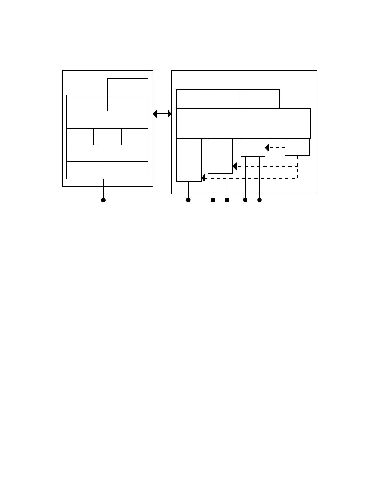
On the left, this illustration shows the ways you can manage and configure
the access point, and on the right, it shows the access point’s general
multiport bridge architecture.
13
Page 14
Chapter 1: Getting Started
Management and Configuration
MIB
DHCP
TCP/IP
TFTP
File
System
RS-232 Connector
HTTP
Configuration Port
DHCP
Agent
Telnet
Configuration
Settings
Multiport Bridge
Forwarding
Database
Ethernet
Port
Ethernet
Connection
Spanning
Tree
Radio
Port 1
Antenna
Connection
Wireless ARP
Server
Bridging
Radio
Port 2
Antenna
Connection
Figure 1. Access Point Architecture
IP
Port
Access points are multiport (Ethernet-to-wireless) bridges, and because
wireless end devices operate similarly to other Ethernet devices, all your
existing Ethernet applications will work with the wireless network without
any special networking software. Any access point, except the root access
point, can concurrently receive hello messages on its Ethernet port, its
radio port, and its IP tunnel port. However, an access point can use only
one port to attach to the network. Port priorities are structured as follows:
1. Ethernet
2. IP tunnel
3. Radio
Unlike the physical Ethernet and radio ports, the IP tunnel port does not
have its own output connector. It is a logical port that provides IP
encapsulation services for frames that must be routed to reach their
destinations. Once frames are encapsulated, they are transmitted or
received through the Ethernet or radio port.
Wireless end devices may use power management to maintain battery life.
These end devices periodically wake up to receive frames that arrived
while their radio was powered down. The access point automatically
provides a pending message delivery service that holds frames until the
end device is ready to receive them.
14
Page 15

AT-WA7500 and AT-WA7501 Installation and User’s Guide
Features This table lists the features of the access points.
Table 1. Access Point Feature Comparison
Feature AT-WA7500 AT-WA7501
Access Point Yes Yes
Point-to-Point Bridge (Wireless
Yes Yes
Bridge)
Wireless Access Point (WAP) or
Yes Yes
Repeater
Secure Wireless Hops (SWAP) Yes Yes
Secure Wireless Hops (TLS or
Yes Yes
TTLS)
Radios 802.11g*
802.11b
802.11a
802.11g*
802.11b
802.11a
Dual Radio Support Yes Yes
Wi-Fi Compliant Yes Yes
Wi-Fi Protected Access (WPA) for
Yes Yes
802.1x mode or PSK mode.
802.1x Authenticator Yes Yes
802.1x Authentication Server Yes Yes
Access Control List (ACL) Server Yes Yes
Password Server Yes Yes
Secure Web Browser Interface
Yes Yes
(HTTPS)
10BaseT/100BaseTx Yes Yes
Fiber Optics Option No Yes
Serial Port Yes Yes
Data Link Tunneling Yes Yes
IP Tunneling Yes Yes
Antenna Diversity Yes Yes
Non-incentive Antenna System Yes Yes
NEMA 4/IP 54 Protection No Yes
Power Supply No AC
15
Page 16

Chapter 1: Getting Started
Table 1. Access Point Feature Comparison (Continued)
Feature AT-WA7500 AT-WA7501
Power Over Ethernet Yes Yes
Heater Option No Yes
* The 802.11g radio is sometimes referred to as the 802.11b/g radio
because it can be configured to communicate with any 802.11b and
802.11g radios that have the same SSID and security settings. For details,
see “About the Radios” on page 97.
Other features of all access points include:
the ability to be managed by the Wavelink Avalanche client
management system, Allied Telesyn manager, a web browser, telnet,
and SNMP.
the ability to be a DHCP server or client and a NAT server.
the ability to be an ARP server.
What’s New for
Software Releases
2.3?
easy software distribution using the distributed upgrade server.
advanced filtering of wired data traffic.
enhanced power management for wireless end devices.
fast roaming reliability for wireless end devices.
load balancing.
basic WEP 64, WEP 128, or WEP 152 security for 802.11g, 802.11b,
or 802.11a radios.
Software release 2.3 can only be installed on the Allied Telesyn
AT-WA7500 and AT-WA7501 access points.
Note
To determine the model of your access point, from the menu choose
Maintenance > About this Access Point. In the Config String
field, the first five characters tell you the model.
New features include these items:
Dual 802.11g radios: The access points support dual 802.11g radios.
16
Wireless hops and wireless bridging: The 802.11g radio supports
wireless hops and wireless bridging. It also supports WPA security and
802.1x security across the wireless hops.
Other new 802.11g radio features: The 802.11g radio now supports
antenna diversity, mixed 802.11g and 802.11b modes, and medium
Page 17

AT-WA7500 and AT-WA7501 Installation and User’s Guide
reservation (including a fragmentation threshold and a reservation
threshold).
AT-WA7500 Configuration Wizard: You can use the configuration
wizard to help you configure and maintain your access point network.
Ability to configure different SSIDs to use different authentication
servers.
Understanding
the LEDs
The AT-WA7500 and AT-WA7501 access points have five LEDs. To
understand the LEDs during normal use, see the next table. To use the
LEDs to help troubleshoot the radios, see “Troubleshooting the Radios” on
page 251.
Table 2. LED Descriptions
Icon LED Description
Power Remains on when power is applied.
Wireless #1 Blinks when a frame is transmitted or
received on the radio port for the radio
installed in radio slot 1.
Wireless #2 Blinks when a frame is transmitted or
received on the radio port for the radio
installed in radio slot 2 (if a second radio
is installed).
Wired LAN Blinks when a frame is transmitted or
received on the Ethernet port.
Root/error Blinks if this device is configured as the
root. It remains on if an error is detected.
17
Page 18
Chapter 1: Getting Started
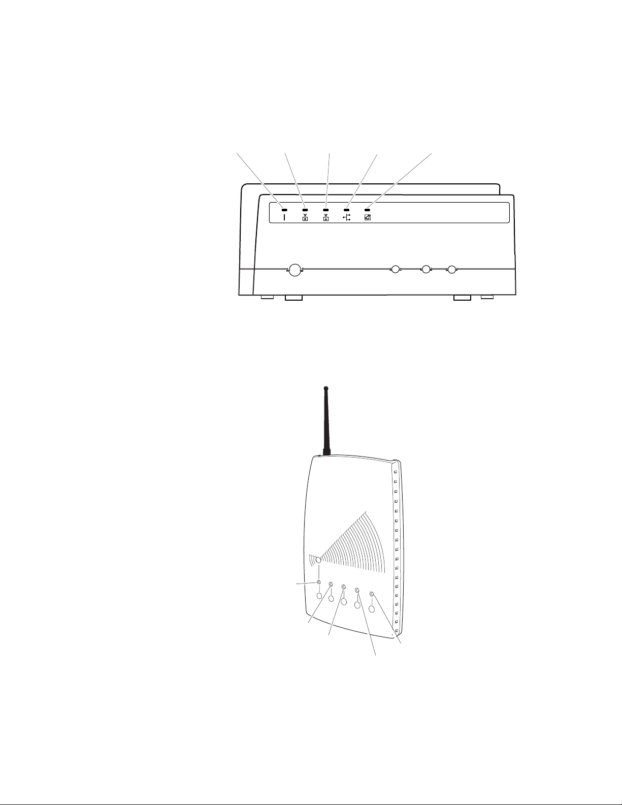
This illustration shows the LEDs that are on the AT-WA7501 access point.
For help understanding these LEDs, see the LED Descriptions table on
page 17.
Allied Telesyn
Readiness
Indicator
Power
Wireless#1Wireless
#2
Wired LAN
Figure 2. AT-WA7501 LEDs
This illustration shows the LEDs that are on the AT-WA7500 access point.
For help understanding these LEDs, see the LED Descriptions table on
page 17.
Universal Access Point
Power
Wireless #1
Wireless #2
™
Wired LAN
Allied Telesyn
Readiness
Indicator
18
21XXT018.eps
Figure 3. AT-WA7500 LEDs
Page 19

AT-WA7500 and AT-WA7501 Installation and User’s Guide
Understanding
the Ports
The access point may have up to four ports.
Table 3. Port Descriptions
Port Description
Power (Not AT-WA7500,
optional AT-WA7501)
Serial Used with an RS-232 null-modem cable,
Ethernet 10BaseT/100BaseTx port. Used with an
Fiber optic
(Not AT-WA7500,
optional AT-WA7501)
Used with an appropriate power cable,
this port connects the access point to an
AC power source.
this port connects the access point to a
terminal or PC to perform configuration.
appropriate cable, this port connects the
access point to your Ethernet network.
The access point auto-negotiates with the
device it is communicating with so that the
data rate is set at the highest rate at which
both devices can communicate.
Optional 100BaseFX port. You must use a
patch cable with a female MT-RJ
connector to connect the access point to
your MT-RJ, SC, or ST fiber optic
network.
To access the ports on the AT-WA7501, you must remove the cable
access door.
To remove the AT-WA7501 cable access door
1. Unscrew the two thumbscrews on the cable access door.
2. Remove the door.
This illustration shows the ports that are on the AT-WA7501. For help
understanding these ports, see the Port Descriptions table on page 19.
19
Page 20
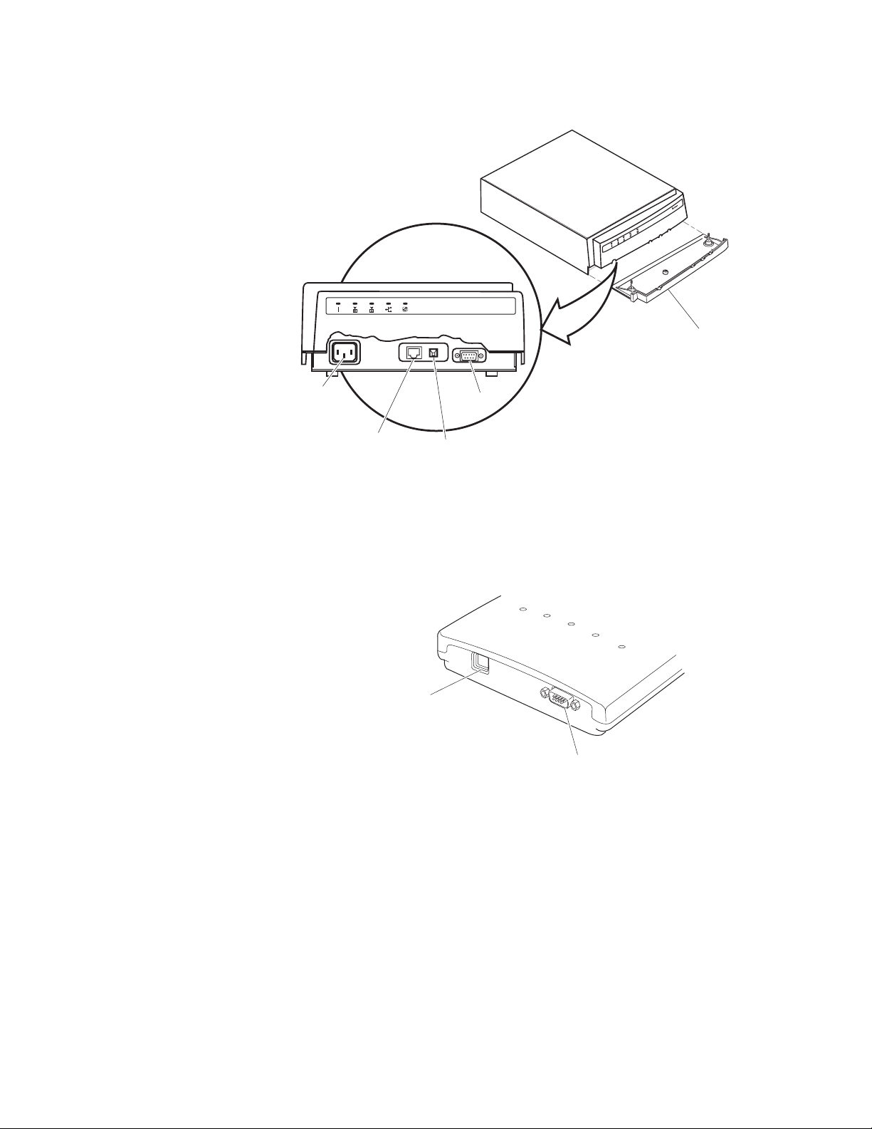
Chapter 1: Getting Started
Cable
access
door
Power port
(optional)
10BaseT/
100BaseTx
Ethernet port
Serial
port
Fiber optic
port (optional)
Figure 4. AT-WA7501 Ports
The AT-WA7500 ports are located on the bottom of the access point. This
illustration shows the ports that are on the AT-WA7500. For help
understanding these ports, see the Port Descriptions table on page 19.
10BaseT/100BaseTx
Ethernet port
Serial port
Figure 5. AT-WA7500 Ports
20
For more information on connecting the ports, see Chapter 2, “Getting
Started” on page 11.
Page 21
How the Access Point Fits in Your Network
In general, the access point forwards data from wireless end devices to
the wired Ethernet network. You can also use the access point as a pointto-point bridge, or if your access point has two radios, you can use it as a
point-to-multipoint bridge or a WAP. Use the access point in the following
locations and environments.
Table 4. Access Point Environments
Access Point Environment
AT-WA7500 Use in most indoor environments.
AT-WA7501 Use in locations where an access point is
exposed to extreme environments.
The access point supports a variety of network configurations. These
configurations are explained in the following sections:
AT-WA7500 and AT-WA7501 Installation and User’s Guide
Using One Access
Point in a Simple
Wireless Network
“Using One Access Point in a Simple Wireless Network” on page 21
“Using Multiple Access Points and Roaming Wireless End Devices” on
page 23
“Using an Access Point as a WAP” on page 25
“Using Access Points to Create a Point-to-Point Bridge” on page 30
“Using Dual Radio Access Points for Redundancy” on page 37
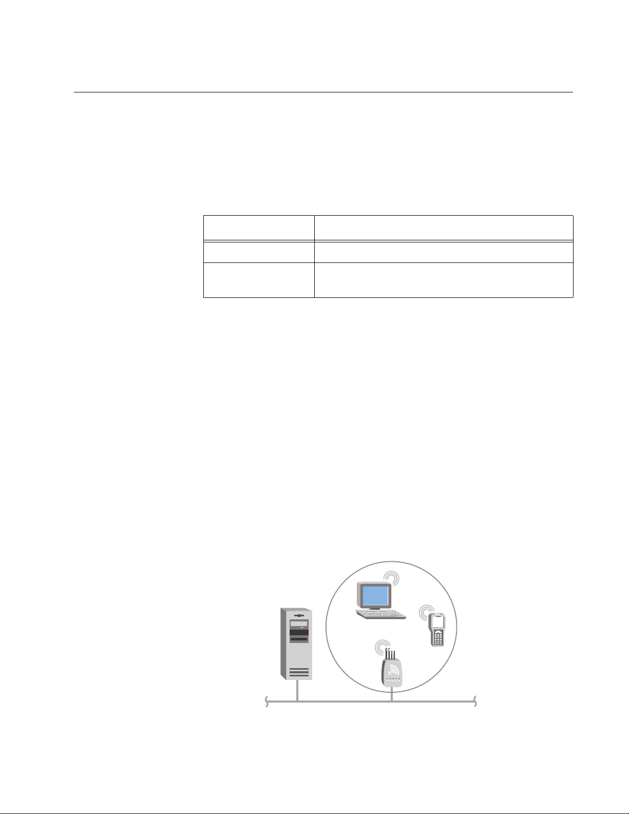
You can use an access point to extend your existing Ethernet network to
include wireless end devices. The access point connects directly to your
wired network and the end devices provide a wireless extension of the
wired LAN.
This illustration shows a simple wireless network with one access point
and some wireless end devices.
Host
Access
point
Ethernet
Figure 6. Simple Wireless Network
21
Page 22
Chapter 1: Getting Started
In a simple wireless network, the access point that is connected to the
wired network serves as a transparent bridge between the wired network
and wireless end devices.
To install a simple wireless network
1. Configure the initial IP address. For help, see “Configuring the Access
Point (Setting the IP Address)” on page 38.
2. Install the access point. For help, see Chapter 2, “Getting Started” on
page 11.
3. Configure the Ethernet network. For help, see Chapter 3, “Configuring
the Ethernet Network” on page 64.
4. Configure the radios. For help, see Chapter 4, “Configuring the
Radios” on page 96.
5. Decide what level of security you want to implement in your network.
For help, see Chapter 6, “Configuring Security” on page 169.
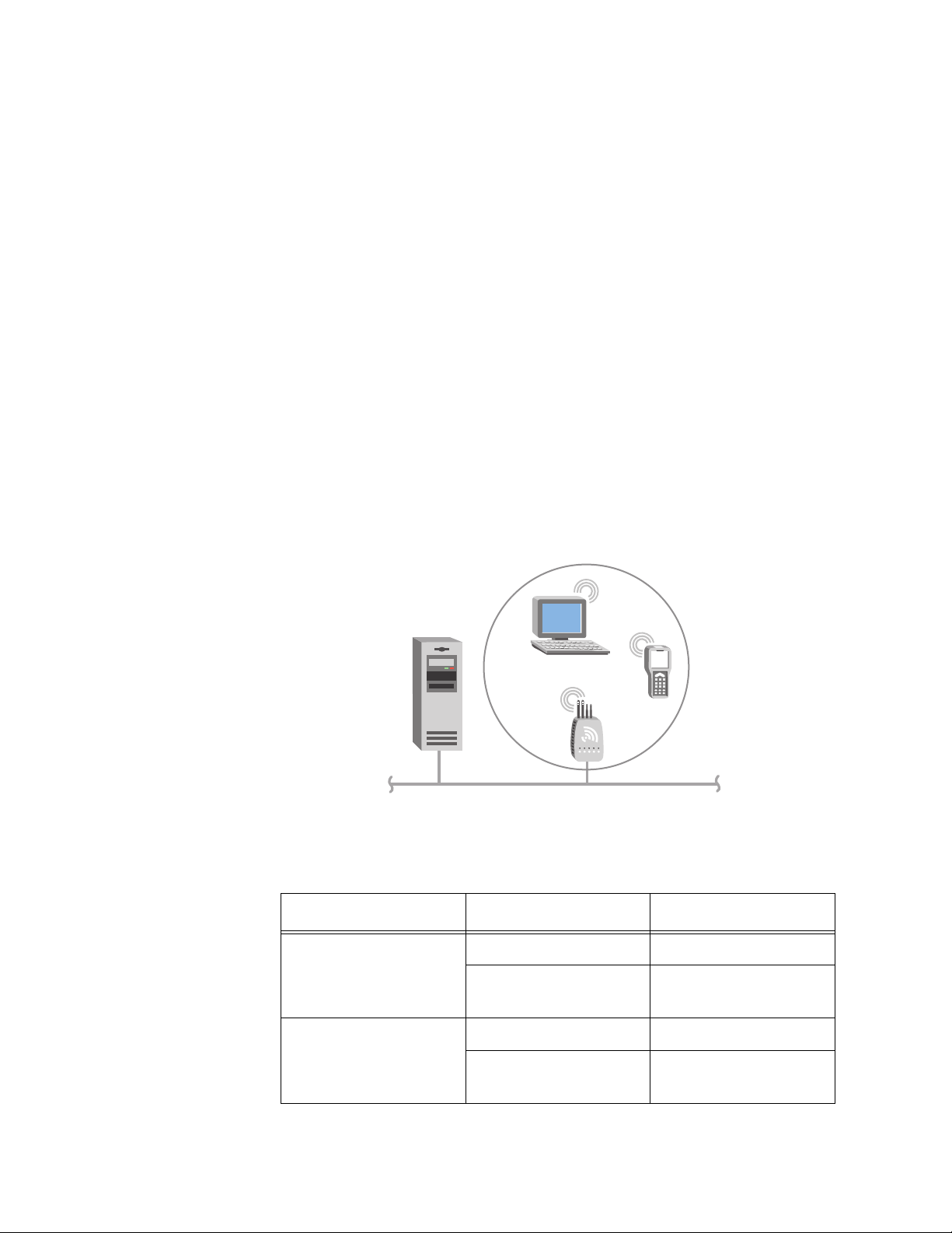
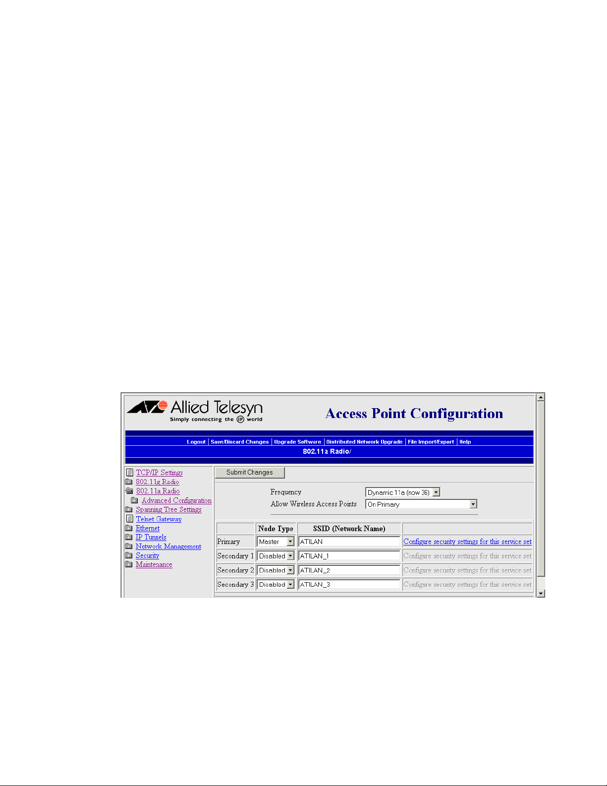
Example - Configuring an 802.11g Access Point
Host
Access
point
Ethernet
Figure 7. 802.11g Access Point
Table 5. 802.11g Access Point Parameter Settings
Screen Parameter Access Point
802.11g Radio Node Type Master
SSID (Network
Name)
Manufacturing
22
Spanning Tree
Settings
Root Priority 5
Ethernet Bridging
Enabled
Checked
Page 23
AT-WA7500 and AT-WA7501 Installation and User’s Guide
Allied Telesyn recommends that you always implement some type of
security.
Using Multiple
Access Points and
Roaming
Wireless End
Devices
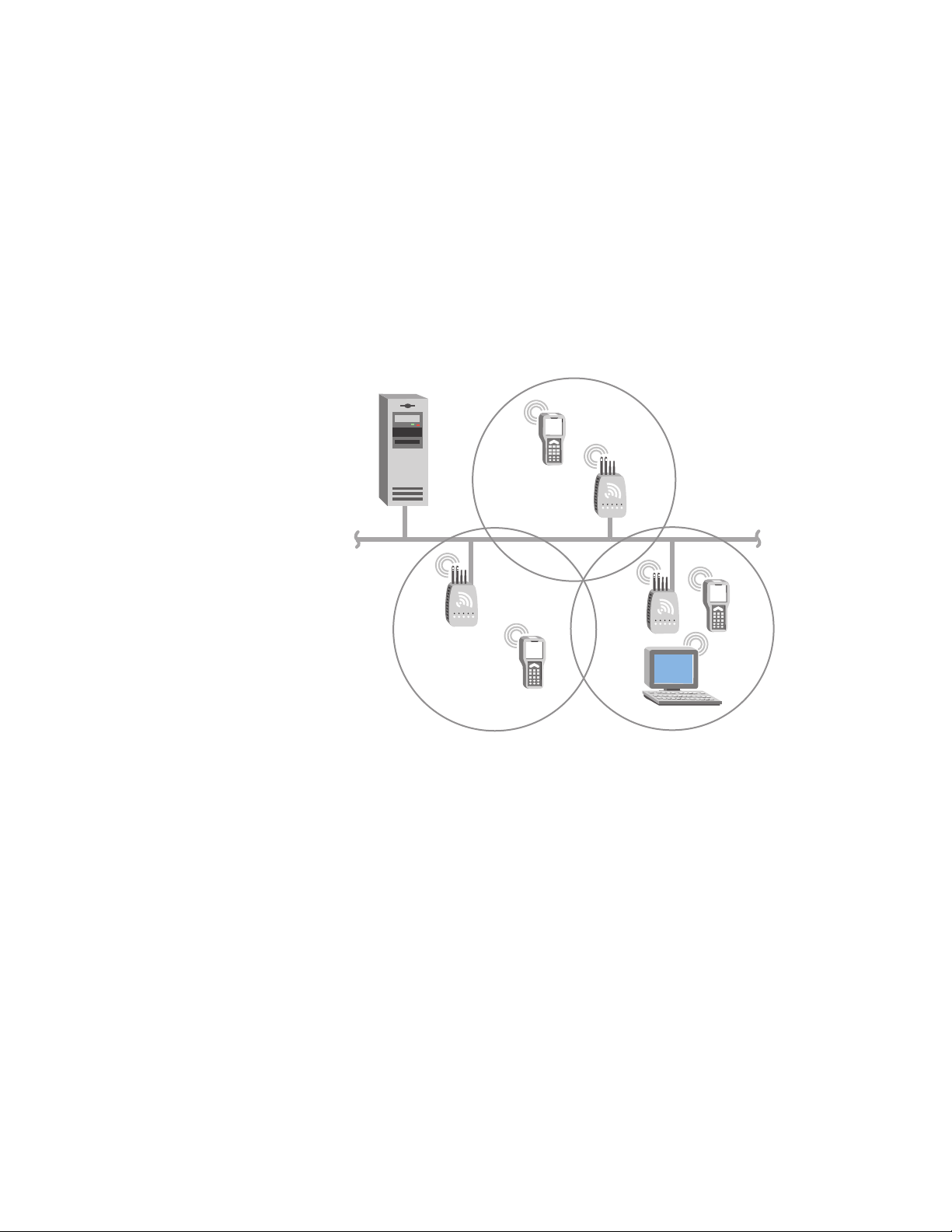
For larger or more complex environments, you can install multiple access
points so wireless end devices can roam from one access point to another.
Multiple access points establish coverage areas or cells similar to those of
a cellular telephone network. End devices can connect with any access
point that is within range and belongs to the same wireless network.
This illustration shows a wireless network with multiple access points.
Wireless end devices can roam between the access points to
communicate with the host and other end devices.
Host
Ethernet
Figure 8. Multiple Access Points with Roaming End Devices
An end device initiates a roam when it attaches to a new access point. The
access point sends an attach message to the root access point, which in
turn forwards a detach message to the previous access point, allowing
each access point to update its forwarding database. Intermediate access
points monitor these exchanges and update their forwarding databases.
With the access point’s multichannel architecture, you can have more than
one access point within the same cell area to increase throughput and
provide redundancy. For more information, see “Using Dual Radio Access
Points for Redundancy” on page 37.
To install multiple access points with roaming end devices
1. Follow the instructions for installing a simple wireless network in “Using
One Access Point in a Simple Wireless Network” on page 21.
23
Page 24
Chapter 1: Getting Started
2. Configure the LAN ID. For help, see “Configuring the Spanning Tree
Parameters” on page 136.
3. Configure one of the access points to be a root access point. For help,
see “About the Primary LAN and the Root Access Point” on page 131.
4. If your network has a switch that is not IEEE 802.1d-compliant and is
located between access points, configure data link tunneling. For help,
see “About Ethernet Bridging/Data Link Tunneling” on page 134.
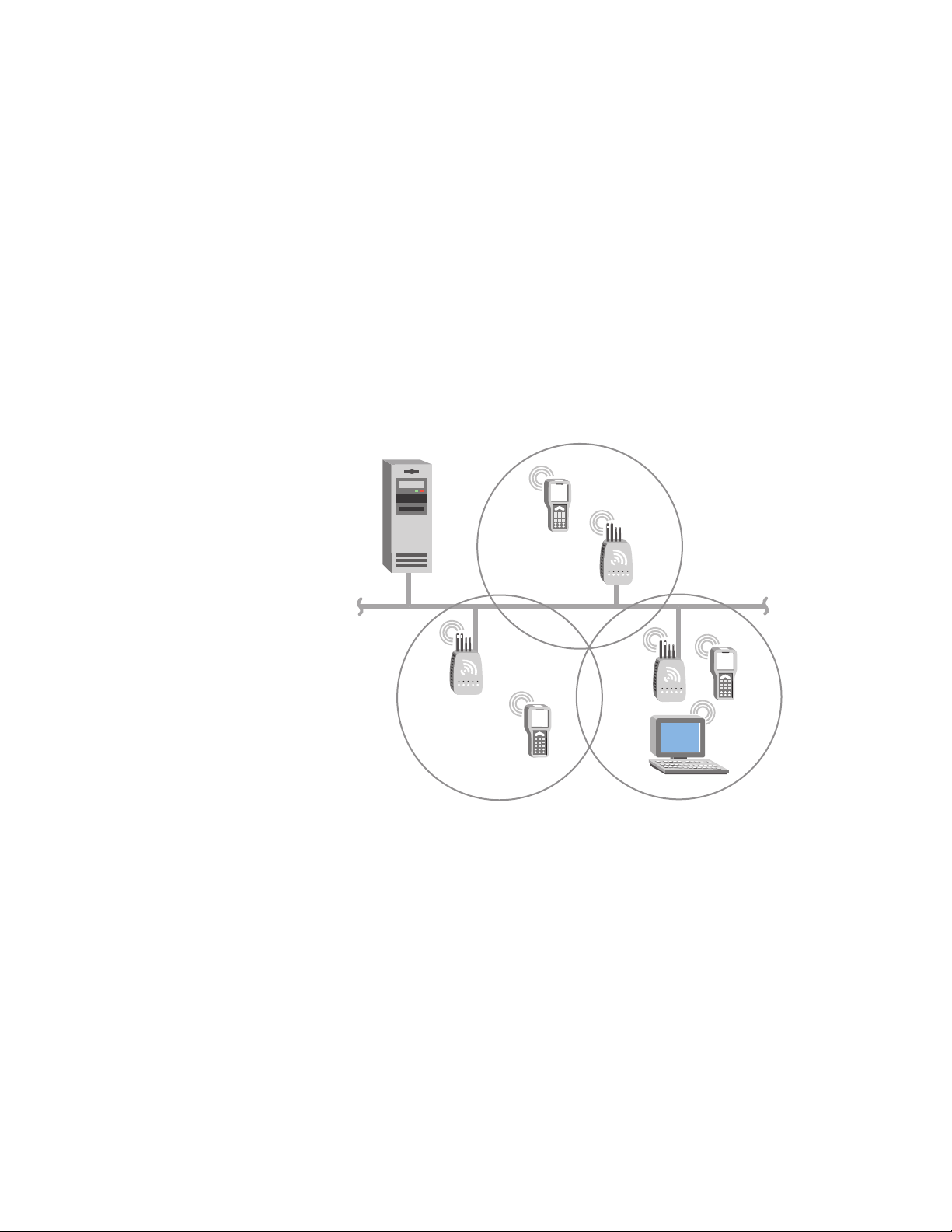
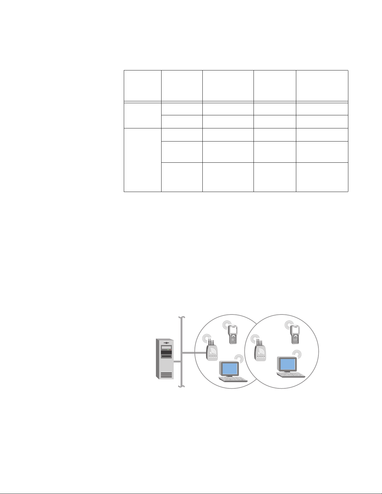
Example - Configuring an 802.11g Access Point with Roaming End
Devices
In this example, there is one 802.11g radio in each access point. Wireless
end devices can roam between the access points to communicate with the
host and other end devices.
Host
AP2
Ethernet
AP1
AP3
Figure 9. 802.11g Access Point with Roaming End Devices
24
Page 25

AT-WA7500 and AT-WA7501 Installation and User’s Guide
Table 6. 802.11g Access Points Parameter Settings
AP1
Screen Parameter
802.11g
Radio
Spanning
Tree
Settings
The access points communicate with each other through the spanning
tree. The wireless end devices are configured as stations with LAN ID set
to 0 and SSID set to Op3rat!ons.
Node Type Master Master Master
SSID Op3rat!ons Op3rat!ons Op3rat!ons
LAN ID000
Root
Priority
Ethernet
Bridging
Enabled
Secondary
LAN Bridge
Priority
802.11g
Radio
(Root)
543
Checked Checked Checked
000
AP2
802.11g
Radio
AP3
802.11g
Radio
Using an Access
Point as a WAP
You can extend the range of your wireless network by configuring a dual
radio access point as a wireless access point (WAP). The WAP and the
wireless end devices it communicates with comprise a secondary LAN.
You can position WAPs in strategic locations so they receive data from
end devices and then forward the data to the wired network. This
configuration can be useful when distance or physical layout impedes
radio reception and transmission.
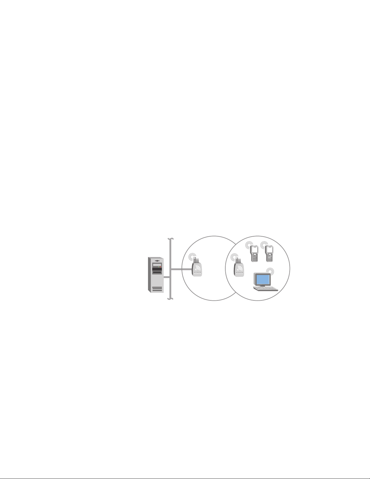
This illustration shows a simple wireless network with one access point
and one WAP. Wireless end devices use the WAP to forward data to the
access point, which forwards data to the host. If you do not want end
devices to also be able to communicate directly with the access point, use
a different SSID for the access point master radio and the WAP station
radio.
25
Page 26

Chapter 1: Getting Started
Host
Access
point
WAP
Ethernet
Figure 10. Access Point as a WAP
WAPs send data from end devices to the access points via wireless hops.
Wireless hops are formed when data from end devices move from one
access point to another access point through the radio ports. The master
radio in the access point transmits hello messages, which allow the WAPs
to attach to the spanning tree in the same way as access points.
The number of radios required in the WAP depends on the type of radio
installed:
If you have an 802.11a radio, the WAP only needs one radio because
this radio can simultaneously be a master and a station. This radio will
create wireless hops automatically when it cannot communicate to the
wired network.
If you have an 802.11g or 802.11b radio, the WAP must contain two
radios: one configured as master and one as station. The WAP master
radio must match the end devices radios, and the WAP station radio
must match the master radio in the access point.
WAPs must be on the same IP subnet as the access point. Also, data from
wireless end devices should not go through more than three wireless hops
before it gets to an access point on the primary LAN.
The following procedure explains how to install a simple wireless network
with a WAP and no roaming end devices. For help installing a simple
wireless network with a WAP and roaming end devices, see the two
examples in the next sections.
To install a simple wireless network with a WAP and no roaming end
devices
1. Follow the instructions for installing a simple wireless network in the
section “Using One Access Point in a Simple Wireless Network” on
page 21.
26
2. Configure the LAN ID. For help, see “Configuring the Spanning Tree
Parameters” on page 136.
Page 27
AT-WA7500 and AT-WA7501 Installation and User’s Guide
3. (802.11g and 802.11b) Configure the station radio in the WAP to
communicate with one of the master radio service sets in the access
point:
a. From the main menu, click the link corresponding to the station
radio. The radio screen appears.
b. In the Primary service set Node Type field, choose Station.
c. In the Primary service set SSID (Network Name) field, type the
SSID. In this example, the SSID is Manufacturing.
d. Click Submit Changes to save your changes. The screen updates.
4. To activate your changes, from the menu bar click Save/Discard
Changes, and then click Save Changes and Reboot. For help, see
“Saving Configuration Changes” on page 46.
5. Configure the master radio in the WAP to communicate with the end
devices. For help, see Chapter 4, “Configuring the Radios” on page 96.
6. Configure the master radio in the access point:
a. From the main menu, click the link corresponding to the master
radio. The radio screen appears.
b. In the Frequency field, choose the radio frequency of your wireless
network.
c. (802.11a only) Make sure the Allow Wireless Access Points field is
On Primary.
d. In the Primary service set Node Type field, choose Master.
27
Page 28
Chapter 1: Getting Started
e. In the Primary service set SSID (Network Name) field, type the
SSID that matches the SSID of the end device radio. In this
example, the SSID is Manufacturing.
7. Click Submit Changes to save your changes. To activate your
changes, from the menu bar click Save/Discard Changes, and then
click Save Changes and Reboot. For help, see “Saving Configuration
Changes” on page 46.
8. Configure the access point to be a root access point. For help, see
“About the Primary LAN and the Root Access Point” on page 131.
9. Click Submit Changes to save your changes. To activate your
changes, from the menu bar click Save/Discard Changes, and then
click Save Changes and Reboot. For help, see “Saving Configuration
Changes” on page 46.
Example - Configuring an 802.11g WAP With No Roaming End
Devices
In this example, there is one 802.11g radio in the access point and there
are two 802.11g radios (802.11g Radio-1 and 802.11g Radio-2) in the
WAP. Wireless end devices only communicate with the WAP; they are not
allowed to communicate directly with the access point.
Host
Access
point
WAP
Ethernet
Figure 11. 802.11g WAP with No Roaming End Devices
28
Page 29
AT-WA7500 and AT-WA7501 Installation and User’s Guide
Table 7. 802.11g Access Point and WAP Parameter Settings
Screen Parameter
802.11g
Radio
Spanning
Tree
Settings
Node Type Master Master Station
SSID Manufacturing Warehouse Manufacturing
LAN ID 11 11 11
Root
Priority
Ethernet
Bridging
Access Point
802.11g
WAP
802.11g
Radio-1
50(not
Checked Checked (not
WAP 802.11b
Radio-2
applicable)
applicable)
Enabled
You need to configure the wireless end devices to have the same SSID,
LAN ID, and frequency as the WAP radio. You do not need to configure
any secondary LAN settings because the WAP is not connected to a
secondary LAN.
Allied Telesyn recommends that you always implement some type of
security.
Example - Configuring an 802.11a WAP With Roaming End Devices
In this example, there is one 802.11a radio in the access point and there is
one 802.11a radio in the WAP. Wireless end devices can roam between
the WAP and the access point.
Host
Access
point
WAP
Ethernet
Figure 12. 802.11a WAP with Roaming End Devices
29
Page 30

Chapter 1: Getting Started
Table 8. 802.11a Access Point and WAP Parameter Settings
Screen Parameter
802.11a
Radio
Spanning
Tree
Settings
You need to configure the wireless end devices to have the same SSID,
LAN ID, and frequency as the WAP radio. You do not need to configure
any secondary LAN settings because the WAP is not connected to a
secondary LAN.
Allow Wireless Access
Points
Primary Node Type Master Master
SSID Manufacturing Manufacturing
LAN ID 11 11
Root Priority 5 0
Ethernet Bridging
Enabled
Secondary LAN Bridge
Priority
Access Point
802.11a
On Primary On Primary
Checked Checked
00
WAP 802.11a
Using Access
Points to Create a
Point-to-Point
Bridge
Allied Telesyn recommends that you always implement some type of
security.
You can use access points to create a point-to-point bridge between two
wired LANs. That is, you can have one access point wired to a primary
LAN in one building and have a second access point wired to a secondary
LAN in another building. This configuration lets wired and wireless end
devices in both buildings communicate with each other, which can be
useful in a campus environment or any other environment where
pavement or other objects prevent installation of a wired link.
This illustration shows two simple wireless networks that are connected
30
Page 31

AT-WA7500 and AT-WA7501 Installation and User’s Guide
with access points that are acting as point-to-point bridges.
Secondary LAN
Host
Primary LAN
Root
Designated
bridge
Figure 13. Access Points as Point-to-Point Bridges
Point-to-point bridges send data from end devices on the secondary LAN
to the root access point via wireless hops. Wireless hops are formed when
data from end devices move from one access point to another access
point through the radio ports. The master radio in the point-to-point bridge
on the primary LAN transmits hello messages, which allow the bridge on
the secondary LAN to attach to the spanning tree in the same way as
access points.
How many radios do you need in each access point?
If you have an 802.11a network, each access point only needs one
radio.
If you have an 802.11g or 802.11b network and the access points are
simply acting as point-to-point bridges, each access point only needs
one radio.
If you have an 802.11g or 802.11b network and you want the
designated bridge to also communicate with wireless end devices
(point-to-multipoint), the designated bridge must have two radios. The
designated bridge master radio must match the end device radios, and
the station radio must match the root master radio.
Data from wireless end devices should not go through more than three
wireless hops before it gets to an access point on the primary LAN.
You need to set the root priorities and secondary LAN bridge priorities for
the bridge on the primary LAN and for the bridge on the secondary LAN:
On the primary LAN bridge, set the root priority to a number that is
greater than the root priority of the secondary LAN bridge. The access
points will not form a point-to-point bridge if the primary LAN bridge
has a lower root priority than the secondary LAN bridge.
On the secondary LAN bridge, set the root priority to 0 and the
secondary LAN bridge priority to a number other than 0.
31
Page 32

Chapter 1: Getting Started
You may also need to adjust the flooding parameters. Here are some
recommendations:
If there are no end devices on the secondary LAN, the bridge on the
secondary LAN can use the default flooding settings. The Secondary
LAN Flooding parameter is disabled.
If there are end devices on the secondary LAN, the bridge on the
secondary LAN should have Secondary LAN Flooding parameter set
to Multicast. If you also want unicast flooding, you can set this
parameter to Enabled.
If there are end devices on the secondary LAN and the end devices
communicate with end devices on another secondary LAN, the root
access point should have its Multicast Flooding parameter set to
Universal. This setting ensures that all ARP requests and multicast
traffic is distributed through a second or third hop.
To install a point-to-point or a point-to-multipoint bridge
1. Follow the instructions for installing a simple wireless network in the
section “Using One Access Point in a Simple Wireless Network” on
page 21.
2. Configure the LAN ID. For help, see “Configuring the Spanning Tree
Parameters” on page 136.
3. Configure one of the master radio service sets in the designated
bridge on the secondary LAN to communicate with the end device
radios.
4. (802.11g and 802.11b) Configure the station radio in the designated
bridge to communicate with one of the master radio service sets in the
point-to-point bridge on the primary LAN:
a. From the main menu, click the link corresponding to the station
radio. The radio screen appears.
b. In the Primary service set Node Type field, choose Station.
c. In the Primary service set SSID (Network Name) field, type the
SSID that matched the SSID of the root access point radio service
set (Step 1). In this example, the SSID is Manufacturing.
d. Click Submit Changes. The screen updates.
5. Configure the spanning tree settings for the designated bridge:
32
a. From the main menu, click Spanning Tree Settings. The Spanning
Tree Settings screen appears.
b. In the Root Priority field, enter 0.
Page 33

AT-WA7500 and AT-WA7501 Installation and User’s Guide
c. In the Secondary LAN Bridge Priority field, enter a number other
than zero.
d. In the Secondary LAN Flooding field, choose Enabled.
6. Configure the spanning tree settings for the point-to-point bridge on the
primary LAN.
a. From the main menu, click Spanning Tree Settings. The Spanning
Tree Settings screen appears.
b. In the Root Priority field, enter a number other than 0.
c. In the Secondary LAN Bridge Priority field, enter 0.
d. In the Secondary LAN Flooding field, choose Disabled.
7. In the roaming end devices will be roaming across an IP router, you
must configure IP tunnels. For help, see “Configuring IP Tunnels” on
page 148.
8. Click Submit Changes to save your changes. To activate your
changes, from the menu bar click Save/Discard Changes, and then
click Save Changes and Reboot. For help, see “Saving Configuration
Changes” on page 46.
9. Configure the master radio in the point-to-point bridge on the primary
LAN:
a. From the main menu, click the link corresponding to the master
radio. The radio screen appears.
b. Make sure the Allow Wireless Access Points field is On Primary.
33
Page 34

Chapter 1: Getting Started
c. In the Primary service set Node Type field, choose Master.
d. In the Primary service set SSID (Network Name) field, type the
SSID. In this example, the SSID is Manufacturing.
e. Click Submit Changes.
10. Configure the spanning tree settings for the point-to-point bridge on
the primary LAN:
a. From the main menu, click Spanning Tree Settings. The Spanning
Tree Settings screen appears.
b. In the Root Priority field, enter a number other than 0.
c. In the Secondary LAN Bridge Priority field, enter 0.
d. In the Secondary LAN Flooding field, choose Disabled.
11. If the roaming end devices will be roaming across an IP router, you
must configure IP tunnels. For help, see “Configuring IP Tunnels” on
page 148.
12. Click Submit Changes to save your changes. To activate your
changes, from the menu bar click Save/Discard Changes, and then
click Save Changes and Reboot. For help, see “Saving Configuration
Changes” on page 46.
Example - Configuring an 802.11g Point-to-Point Bridge
In this example, each access point only has one 802.11g radio. Since the
designated bridge only has a station radio, wireless end devices can only
communicate with the root access point. However, wired devices on the
secondary LAN can communicate with the primary LAN.
Secondary LAN
Host
Primary LAN
Root
Designated
bridge
34
Figure 14. 802.11g Bridge
Page 35

AT-WA7500 and AT-WA7501 Installation and User’s Guide
Table 9. 802.11g Point-to-Point Bridges Parameter Settings
Bridge
Screen Parameter
Primary LAN
(Root)
Bridge
Secondary
LAN
(Designated
Bridge)
802.11g
Node Type Master Station
Radio
Spanning
Tree
Settings
SSID Manufactur-
ing
LAN ID 0 0
Root Priority 5 0
Ethernet Bridging
Checked Checked
Manufacturing
Enabled
Secondary LAN Bridge
01
Priority
Secondary LAN Bridge
Disabled Enabled
Flooding
Allied Telesyn recommends that you implement some type of security.
35
Page 36

Chapter 1: Getting Started
Example - Configuring an 802.11a Point-to-Multipoint Bridge
In this example, each access point only has one 802.11a radio. Since the
802.11a radio can function as a master and a station, wireless end
devices can communicate with either access point.
Secondary LAN
Host
Primary LAN
Root
Designated
bridge
Figure 15. 802.11a Point-to-Point Bridges
Table 10. 802.11a Point-to-Point Bridges Parameter Settings
Bridge
Screen Parameter
Primary LAN
(Root)
Bridge
Secondary
LAN
(Designated
Bridge)
802.11a
Radio
Allow Wireless Access
Points
On Primary On Primary
Node Type Master Master
Spanning
Tree
Settings
SSID Manufactur-
ing
LAN ID 11 11
Root Priority 5 0
Ethernet Bridging
Checked Checked
Manufacturing
Enabled
Secondary LAN Bridge
01
Priority
Secondary LAN Bridge
Disabled Enabled
Flooding
Allied Telesyn recommends that you implement some type of security.
36
Page 37

AT-WA7500 and AT-WA7501 Installation and User’s Guide
Using Dual Radio
Access Points for
Redundancy
You can configure AT-WA7500 units and AT-WA7501 units that have two
802.11g radios, two 802.11b radios, or two 802.11a radios to provide
redundancy for your network.
During normal operations, end devices send frames to the master radio in
one of the access points, which bridges the frames to the wired network. If
a section of the wired network goes down, the master radio receives the
frames, and then the station radio forwards the frames to a master radio in
another access point that is within range.
In each access point, you need to configure one radio’s node type as a
Master, which communicates with the wireless end devices, and configure
the other radio’s node type as a Station, which communicates to another
access point with a master radio and within range.
In this example, AP3 is a dual radio access point. It may be located on a
loading dock or other remote location. During normal operations, AP3
functions as a normal access point, transmitting frames to and from the
host. However, if the Ethernet connection is disrupted, AP3 can function
as a WAP and continue operations by transmitting frames to a master
radio in AP1. AP3 must be within range of AP1.
Host
AP1 AP3
Ethernet
Figure 16. Dual Radio Access Points
To install dual radio access points for redundancy
Follow the instructions for installing a simple wireless network with a
WAP on page 25.
37
Page 38

Chapter 1: Getting Started
Configuring the Access Point (Setting the IP Address)
The access point will work out of the box if you are using a DHCP server to
assign it an IP address. By default, the access point is configured to be a
DHCP client and will respond to offers from any DHCP server. However, if
you are not using a DHCP server to assign an IP address, you can use:
the Allied Telesyn AT-WA7500 Configuration Wizard, but you need to
know the access point IP addresses. You can download this wizard
from the ATI web site. For help, see “Using the ATI AT-WA7500
Configuration Wizard” on page 38.
Note
Your PC must be on the same Ethernet segment as the access
point. Or, if your PC is communicating wirelessly with the access
point, you must have an active radio connection.
Using the ATI
AT-WA7500
Configuration
Wizard
a communications program, such as HyperTerminal, which also
configures other parameters. This program must be installed on a PC
with an open serial port. For help, see “Using a Communications
Program” on page 40.
This manual assumes that you are using a communications program for
your initial configuration, and then using a web browser interface to
perform all other configurations. You can also continue to use a
communications program or you can start a telnet session to configure the
access point.
The AT-WA7500 Configuration Wizard is an easy-to-use Microsoft
®
Windows™-based wizard that lets you:
set the initial IP address for the access point. This wizard eliminates
the need to serially connect a PC to the access point to configure its IP
address.
restore the access point settings to factory defaults. For help, see the
only help and “Restoring the Access Point to the Default
Configuration” on page 239.
recover a failed access point. For help, see the online help and
“Recovering a Failed Access Point” on page 258.
38
upgrade the access point software. For help, see the online help and
“Upgrading the Access Points” on page 261.
After you cofigure the IP address, you can use a web browser or a telnet
session to complete the configuration.
Page 39

AT-WA7500 and AT-WA7501 Installation and User’s Guide
To use the Allied Telesyn AT-WA7500 Configuration Wizard
Note
To use the AT-WA7500 Configuration Wizard, you must have a PC
that is running Windows 95-OSR2/98SE/ME or Windows NT4/2000/
XP.
1. Install the AT-WA7500 Configuration Wizard on your PC. The wizard
can be downloaded either from the documentation CD that is shipped
with the access point, or from the ATI web site.
2. Extract the .zip file, double-click the .exe file, and then follow the
instructions that appear on your screen.
Note
Your PC must be on the same Ethernet segment as the access
point. Or, if your PC is communicating wirelessly with the access
point, you must have an active radio connection.
3. Start the wizard. The Allied Telesyn AT-WA7500 Configuration Wizard
window appears.
4. Select one of the following IP Address configuration options:
Configure a range of IP addresses (default)
Configure specific IP addresses
Obtain IP addresses from a DHCP server on the
network/User current addresses
39
Page 40

Chapter 1: Getting Started
5. Proceed with the IP Address configuration by following the on-screen
menus.
Using a
Communications
Program
You can use a communications program (such as HyperTerminal) to set
the initial IP address for the access point. After you configure the IP
address, you can continue to use the communications program to set
other parameters or you can use a web browser or a telnet session to
complete the configuration.
To use a communications program, you must have
a terminal or PC with an open serial port and the communications
program.
an RS-232 null-modem cable. One end of this cable must be a 9-pin
socket connector to connect to the serial port on the access point.
To use a communications program
1. Use the RS-232 null-modem cable to connect the serial port on the
access point to a serial port on your PC. You may need to remove the
serial port plug.
2. Start the communications program and configure the serial port
communications parameters on your PC, and then click OK. You
should configure the serial port communications parameters to:
Bits per second 9600
Data bits 8
Parity None
Stop bit 1
Flow control None
3. Connect the access point to power. The access point has no On/Off
switch, so it boots as soon as you apply power.
40
Page 41

AT-WA7500 and AT-WA7501 Installation and User’s Guide
4. Press Enter when the message “Starting system” appears on your PC
screen. The Username field appears.
5. In the Username field type the default user name “atilan”, and then
press Enter. The user name is case sensitive.
6. In the Password field type the default password “atilan”, and then
press Enter. The password is case sensitive. The Access Point
Configuration menu appears.
7. Press Enter to access the TCP/IP Settings menu.
8. If you are not using a DHCP server, you need to manually assign an IP
address. Configure these parameters in the TCP/IP Settings menu:
41
Page 42

Chapter 1: Getting Started
IP Address - A unique IP address.
IP Subnet Mask - The subnet mask that matches the
other devices in your network.
IP Router (Gateway) - If the access point will
communicate with devices on another subnet, enter
the address of the router that will forward frames.
Or, if you are using a DHCP server to automatically assign an IP
address to your access point, configure these parameters in the TCP/
IP Settings menu:
DHCP Mode - Set to <Use DHCP if IP Address is
Zero>.
DHCP Server Name - The name of the DHCP server
that the access point is to access for automatic
address assignment. If no server name is specified,
the access point responds to offers from any server.
9. Press Esc to return to the Access Point Configuration menu.
Using a Web
Browser
Interface
10. Choose Save Configuration.
11. Choose Reboot.
When the access point is done rebooting, you are ready to install the
access point in your network. See Chapter 2, “Installing the Access
Points” on page 49.
After you have set the initial IP address, you can configure, manage, and
troubleshoot the access point from a remote location using a web browser
interface. The web browser interface has been tested using Internet
Explorer. Remotely accessing the access point using other browsers may
provide unpredictable results. When using the web browser interface,
keep the following points in mind:
Your session terminates if you do not use it for 15 minutes.
Command Console mode is not available.
Note
If you access the Internet using a proxy server, you must add the IP
address of the access point to your Exceptions list. The Exceptions
list contains the addresses that you do not want to use with a proxy
server.
42
Page 43

AT-WA7500 and AT-WA7501 Installation and User’s Guide
To use a web browser interface
1. Determine the IP address of the access point. If a DHCP server
assigned the IP address, you must get the IP address from the DHCP
server.
2. Start the web browser application.
3. Access the access point using one of these methods:
In the Address field (Internet Explorer) or in the
Location field (Netscape Communicator), enter the IP
address, and press Enter.
From the File menu, choose Open (Internet Explorer)
or choose Open Page (Netscape Communicator). In
the field, enter the IP address and press Enter.
The Access Point Login screen appears.
4. If necessary, enter a user name and a password. The default user
name is “atilan” and the default password is “atilan”. You can define a
user name and password. For help, see “Setting Up Logins” on
page 176.
Or you may want to log in to a secure session.
43
Page 44

Chapter 1: Getting Started
5. Click Login. The TCP/IP Settings screen appears.
Using a Telnet
Session
Your web browser session is established.
Note
Although you can use several different methods to manage the
access point remotely, this manual assumes you are using a web
browser.
After you have configured the IP address, you can configure, manage, and
troubleshoot the access point from a remote location using a telnet
session.
Only one session can be active with the access point at a time. If you
session terminates abruptly or a new login screen appears, someone else
may have accessed the access point. Also, your session terminates if you
do not use it for 15 minutes.
To use a telnet session
1. Determine the IP address of the access point. If a DHCP server
assigned the IP address, you must get the IP address from the DHCP
server.
44
Page 45

AT-WA7500 and AT-WA7501 Installation and User’s Guide
2. From a command prompt, type: telnet IPaddress where IPaddress is
the IP address of the access point.
3. Press Enter.
4. If necessary, enter the user name and press Enter. Then, enter the
password and press Enter. The default user name is “atilan” and the
default password is “atilan”. You can define a user name and
password. For help, see “Setting Up Logins” on page 176. The Access
Point Configuration menu appears.
Your telnet session is established.
45
Page 46

Chapter 1: Getting Started
Saving Configuration Changes
When you are done configuring the access point, you may want to activate
your changes immediately or you may want to save the changes now and
activate them later. If you choose to activate the changes later, they will
become active the next time the access point is booted.
Configuration File Description
Default This configuration file is the factory default
Current When you click Submit Changes, the access
Table 11. Access Point Configuration Files
configuration. For help, see “Restoring the
Access Point to the Default Configuration” on
page 239.
point updates the current configuration file. The
access point does not change the active
configuration file. You can see a list of pending
changes when you click Save/Discard Changes.
Having separate files for the current and active
configurations lets you make changes while the
access point is running without interrupting
communication.
Saved When you click Save/Discard Changes > Save
Changes without Reboot, the access point copies
the current configuration file to the saved
configuration file. Having separate files for the
saved and active configurations lets you make
changes while the access point is running without
interrupting communication.
Active When you click Save/Discard Changes > Save
Changes and Reboot, the access point copies
the current configuration file to the active
configuration file. The active configuration file is
the file that the access point uses.
Note
For the 802.11g radio, when you configure some of the advanced
configuration parameters, you can immediately activate the changes
without rebooting the access point. For instructions, see “Applying
Hot Settings” on page 108.
46
Page 47

AT-WA7500 and AT-WA7501 Installation and User’s Guide
Using a Web
1. On the menu bar, click Save/Discard Changes.
Browser
Interface
Select to use new configuration
settings immediately
This screen appears.
Select to use new configuration
settings the next time you reboot
the access point
Lists possible configuration
changes that still need
to be made
2. Resolve any error messages listed under the heading Possible
3. Verify that all your configuration changes appear in the Pending
4. Click Save Changes and Reboot to reboot the access point and
To discard the changes
Click Discard Pending Changes.
Lists configuration changes
that have been made
Configurations Errors. For help, see “Using the Configuration Error
Messages” on page 240.
Changes box.
immediately use your new active configuration.
Or click Save Changes without Reboot. The access point saves the
changes to its current configuration and continues to run its active
configuration. You need to reboot the access point when you want the
current configuration to become the active configuration.
47
Page 48

Chapter 1: Getting Started
Using a Telnet
Session
1. From the Access Point Configuration menu, choose Save
Configuration.
2. Choose Reboot to reboot the access point and immediately use your
new active configuration.
48
Page 49

Chapter 2
Installing the Access Points
This chapter explains how to install the Allied Telesyn AT-WA7500 and
AT-WA7501 access points in your data collection network, provides some
tips on how to position access points to improve your network
performance, and provides some external antenna guidelines. This
chapter covers these topics:
“Installation Guidelines” on page 50
“Installing the AT-WA7501” on page 52
“Installing the AT-WA7500” on page 54
“Connecting to Your Fiber Optic Network” on page 55
“Connecting Power Over Ethernet” on page 59
“External Antenna Placement Guidelines” on page 60
49
Page 50

Chapter 2: Installing the Access Points
Installation Guidelines
Allied Telesyn recommends that you have an Allied Telesyn-certified RF
specialist conduct a site survey to determine the ideal locations for all your
Allied Telesyn wireless network devices. To conduct a proper site survey,
you need to have special equipment and training.
The following general practices should be followed in any installation:
Locate access points centrally within areas requiring coverage.
Overlap access point radio coverage areas to avoid coverage holes.
Position the access point so that its LEDs are visible. The LEDs are
useful for troubleshooting.
Install wired LAN cabling within node limit and cable length limitations.
Use an uninterruptible power supply (UPS) when AC power is not
reliable.
Proper antenna placement can help improve range. For information about
antenna options, contact your local Allied Telesyn representative. For
more guidelines, see “External Antenna Placement Guidelines” on
page 60.
When determining ideal locations for the access points, be aware that you
may see network performance degradation from microwave ovens,
cordless telephones, and other access points. For more information, see
the next sections.
Note
Microwave ovens, cordless telephones, and other access points do
not degrade the network performance of the 802.11a radio.
Microwave Ovens Microwave ovens operate in the same frequency band as 802.11g and
802.11b radios; therefore, if you use a microwave oven within range of
your wireless network, you may notice network performance degradation.
Both your microwave oven and your wireless network will continue to
function, but you may want to consider relocating your microwave oven
out of range of your access point.
50
Cordless
Telephones
If you have an 802.11g or 802.11b radio in your access point, the radio
may experience interference from some cordless telephones. For optimal
performance, consider operating cordless telephones out of range of your
access points.
Page 51

AT-WA7500 and AT-WA7501 Installation and User’s Guide
Other Access
Points
Access points that are configured for the same frequency and that are in
the same radio coverage area may interfere with each other and decrease
throughput. You can reduce the chance of interference by configuring
access points at least five channels apart, such as channels 1, 6, and 11.
51
Page 52

Chapter 2: Installing the Access Points
Installing the AT-WA7501
You can place the AT-WA7501 horizontally or vertically on a desk or
counter. If you want to mount the AT-WA7501 to a wall or beam using an
Allied Telesyn mounting bracket kit, you need one of these mounting kits:
Mounting bracket kit (to be purchased separately)
Rotating mounting bracket kit (to be purchased separately)
To order one of these kits, contact your Allied Telesyn representative.
To maintain the IP54 environmental rating, you must mount the
AT-WA7501 in either the horizontal or vertical position. If you order the
AT-WA7501 with the heater option, you must use one of the mounting
bracket kits to mount the AT-WA7501 with the LEDs facing down.
A variety of external antenna options are available for the AT-WA7501.
Contact your Allied Telesyn representative for information about the
various antenna options, including higher gain and directional antennas.
For more information about antennas and antenna accessories, see
“Antennas and Antenna Accessories” on page 247.
To install the AT-WA7501, do the following procedure:
1. Attach the antenna or antennas. For more information, see “External
Antenna Placement Guidelines” on page 60.
Note
If the AT-WA7501 has an 802.11a full-range radio, you must use the
antennas that are already attached to the antenna connectors.
2. Mount the AT-WA7501. For help see the AT-WA7501 Quick Install
Guide and the instructions that shipped with the bracket kit.
3. Connect the AT-WA7501 to your wired LAN (unless you are using it as
a WAP). For help, see “Connecting the AT-WA7501 to Your Wired
LAN” on page 52.
4. Connect the AT-WA7501 to power. For help, see “Connecting the
AT-WA7501 to Power” on page 53.
When you are done installing the access points, you need to configure
them to communicate with your network.
Connecting the
AT-WA7501 to
Your Wired LAN
52
Unless you are using the AT-WA7501 as a WAP, you need to connect it to
your Ethernet or fiber optic network. To connect the AT-WA7501 to your
fiber optic network, you must have a AT-WA7501 with the fiber optic
Page 53

AT-WA7500 and AT-WA7501 Installation and User’s Guide
option. For help, see “Connecting to Your Fiber Optic Network” on
page 55.
To connect the AT-WA7501 to the Ethernet network
Attach one end of the Ethernet cable to the 10BaseT/100BaseTx port
on the AT-WA7501 and attach the other end to your Ethernet network
or a power bridge (if you are using power over Ethernet), a Cisco
power bridge or another 802.3af-compliant power bridge.
Connecting the
AT-WA7501 to
Power
If your AT-WA7501 has the internal power supply option, you can use a
power cord to connect the AT-WA7501 directly to an AC power outlet.
Caution
You must use the appropriate Allied Telesyn power supply with
these devices or equipment damage may occur.
Attention: Vous devez utiliser la source d’alimentation Allied Telesyn
adéquate avec cet appareil sinon vous risquez d’endommager
l’équipement.
If you are using the power over Ethernet option, you must have the power
bridge or another 802.3af-compliant power bridge. For help, see
“Connecting Power Over Ethernet” on page 59 and the documentation that
came with your power bridge.
To connect the AT-WA7501 to power
Plug one end of the power cord into the power port on the AT-WA7501
and plug the other end into an AC power outlet. The access point
boots as soon as you apply power.
53
Page 54

Chapter 2: Installing the Access Points
Installing the AT-WA7500
You can place the AT-WA7500 horizontally on a desk or counter. The
AT-WA7500 also ships with a mounting bracket that lets you mount it
vertically to a wall. Additional mounting options that you can use with the
mounting bracket include a cubicle bracket that lets you mount the
AT-WA7500 on a cubicle wall or in a locking bracket.
Cubicle bracket kit
Locking bracket kit
To order one of these kits, contact your Allied Telesyn representative.
Allied Telesyn also offers a variety of antennas and antenna accessories.
For more information, see “Antennas and Antenna Accessories” on page
247.
To install the AT-WA7500, do the following:
1. Attach the antenna or antennas. For more information, see “External
Antenna Placement Guidelines” on page 60.
Connecting the
AT-WA7500 to
Your Wired LAN
and Power
Note
If the AT-WA7500 has an 802.11a full-range radio, you must use the
antennas that are already attached to the antenna connectors.
2. Mount the AT-WA7500. For help see the AT-WA7500 Quick Install
Guide and the instructions that shipped with the bracket kit.
3. Connect the AT-WA7500 to your wired LAN (unless you are using it as
a WAP). For help, see “Connecting the AT-WA7500 to Your Wired
LAN and Power” on page 54.
4. Connect the AT-WA7500 to power. For help, see “Connecting the
AT-WA7500 to Your Wired LAN and Power” on page 54.
When you are done installing the access points, you need to configure
them to communicate with your network.
Unless you are using the AT-WA7500 as a WAP, you must connect it to
your Ethernet network. To connect the AT-WA7500 to your Ethernet
network and to power, you must first connect it to a power bridge or
another 802.3af-power bridge. For help, see “Connecting Power Over
Ethernet” on page 59 and the documentation that shipped with your power
bridge.
54
Page 55

Connecting to Your Fiber Optic Network
You can order your AT-WA7501 access point with a fiber optic option.
Using an appropriate patch cord and adapter (as described in the next
section), you can connect your access point to:
an MT-RJ network.
a square connector (SC) network.
a straight tip (ST) network.
AT-WA7500 and AT-WA7501 Installation and User’s Guide
Using and
Purchasing the
Required Patch
Cord and
Adapter
To access
To connect the access point with the fiber optic option to your fiber optic
network, you must have a patch cord and an adapter.
The access point fiber optic port consists of a male MT-RJ connector
interface. Therefore, the patch cord must have a female MT-RJ connector
that you insert into the access point fiber optic port.
point
Insert a female MT-RJ
connector into the
fiber optic port
To access
point
Do not insert a male
MT-RJ connector into
the fiber optic port
Figure 17. Patch Cord
Note
Inserting a male MT-RJ connector into the fiber optic port may result
in unreliable operation because there is no internal mechanism to
ensure the alignment of the fiber when using male-to-male
connectors. Such a connection may temporarily provide some level
of connectivity, despite a high level of signal loss. However, any
movement of the cable or change in cable tension could cause
complete loss of signal.
Both the connector at the other end of the patch cord and the adapter you
select depend on the type of network to which the access point is
connected: MT-RJ, SC, or ST.
Patch cords and adapters are available from many different
manufacturers. For help choosing the proper patch cord and adapter,
contact your local Allied Telesyn representative.
55
Page 56

Chapter 2: Installing the Access Points
k
Note
All cables must be multimode, 62.5/125 µm.
Connecting to an
MT-RJ Network
To connect to an MT-RJ network, you need:
a patch cord with a female MT-RJ connector to insert into the access
point’s male MT-RJ fiber optic port, and another female MT-RJ
connector to insert into the MT-RJ adapter.
an adapter for connecting the patch cord to the MT-RJ network.
To connect to an MT-RJ network
1. Remove any cable protectors attached to the patch cord and adapter.
2. Connect the access point to your network as shown in the next
illustration.
Female
MT-RJ connector
Female
To access point
Patch cord
MT-RJ connector
MT-RJ adapter
To
MT-RJ
networ
Connecting to an
SC Network
56
Figure 18. Connecting to an MT-RJ Network
Note
The patch cord shown above must connect to the access point with
a female MT-RJ connector. For details, see “Using and Purchasing
the Required Patch Cord and Adapter” on page 55.
To connect to an SC network, you need:
a patch cord with a female MT-RJ connector to insert into the access
point’s male MT-RJ fiber optic port, and an SC connector to insert into
the SC adapter.
an adapter for connecting the patch cord to an SC network.
To connect to an SC network
1. Remove any cable protectors attached to the patch cord and adapter.
Page 57

AT-WA7500 and AT-WA7501 Installation and User’s Guide
k
k
2. Connect the access point to your network as shown in the next two
illustrations.
Female
MT-RJ connector
To access point
Note
The patch cord shown above must connect to the access point with
a female MT-RJ connector. For details, see “Using and Purchasing
the Required Patch Cord and Adapter” on page 55.
To access point
Patch cord
Female
MT-RJ connector
SC connector
SC adapter
SC connector
To SC
networ
SC connector
SC adapter
Connecting to an
ST Network
SC connector
Patch cord
Note
The patch cord shown above must connect to the access point with
a female MT-RJ connector. For details, see “Using and Purchasing
the Required Patch Cord and Adapter” on page 55.
To connect to an ST network, you need:
To SC
networ
To SC
network
57
Page 58

Chapter 2: Installing the Access Points
k
a patch cord with a female MT-RJ connector to insert into the access
point’s male MT-RJ fiber optic port, and an ST connector to insert into
the ST adapter.
an adapter for connecting the patch cord to the ST network.
To connect to an ST network
1. Remove any cable protectors attached to the patch cord and adapter.
2. Connect the access point to your network as shown in the next
illustration.
Female
MT-RJ connector
To access point
Note
The patch cord shown above must connect to the access point with
a female MT-RJ connector. For details, see “Using and Purchasing
the Required Patch Cord and Adapter” on page 55.
Patch cord
ST connector
ST adapter
ST connector
To
ST networ
To
ST network
58
Page 59

Connecting Power Over Ethernet
T
The AT-WA7500 is powered by power over Ethernet. The AT-WA7501
can be powered by AC power or by power over Ethernet or both. For all
access points, you need a power bridge. For a list of the power bridges
that Allied Telesyn sells, contact your local Allied Telesyn representative.
This illustration shows how you connect the AT-WA7500 to a power bridge
with a typical Ethernet cable to run power over Ethernet.
o AC
AT-WA7500 and AT-WA7501 Installation and User’s Guide
Power bridge
Data In
Main
Power & Data Out
Power
Active
To Ethernet
Figure 19. Power Over Ethernet
To connect power over Ethernet
1. Install the power bridges. For help, see the documentation that
shipped with the power bridge.
2. Use an Ethernet cable to connect the power bridge to the Ethernet port
of the access point.
59
Page 60

Chapter 2: Installing the Access Points
External Antenna Placement Guidelines
Antennas and their placement play a vital role when installing a wireless
network. Every wireless network environment presents its own unique
obstacles. Therefore, the exact range that you will achieve with each
access point is difficult to determine. Allied Telesyn recommends that you
allow an Allied Telesyn-certified RF specialist to perform a site survey
before you install a wireless network. For more information, contact your
local Allied Telesyn representative.
Radio signals may reflect off some obstacles and be absorbed by others.
For example, two radios may achieve up to 305 m (1,000 ft) of range if
positioned outdoors within line of sight, with no obstacles between them.
However, the same two radios may only achieve 152 m (500 ft) of range
when the RF signal has to travel through items such as cubicles. If the
signal must penetrate office walls, the signal range may decrease to 91 m
(300 ft).
Using the proper antennas for your environment and placing them in the
proper areas can help improve range. For information about antenna
options, contact your local Allied Telesyn representative. Here are some
general guidelines for positioning antennas:
Connecting
Antennas to the
Radios
Positioning
Antennas for
802.11g, 802.11b,
and 802.11a
Radios
Place the antenna as high as possible. In an office environment, try to
place it above cubicle walls.
Keep the line-of-sight between the antennas and wireless end devices
clear of metal surfaces (like beams or girders) and large quantities of
paper products.
Do not place a sheet of metal (such as a filing cabinet) between two
antennas.
These next sections provide detailed information about antenna
placement for those access points that can have more than one antenna.
All radios have two ports. The radio in slot 2 uses ports 3 and 4, and the
radio in slot 2 uses ports 1 and 2. If you have only one radio in the access
point, it is in slot 1.
For the 802.11g and 802.11b radios, the primary port is a transmit/receive
port and the secondary port is a receive-only port. The primary port is the
right connector (2 or 4) and the secondary port is the left connector (1 or
3). If you only attach one antenna to the 802.11g or 802.11b radio, you
must attach it to the primary port.
For the 802.11a radio, both ports are automatically transmit/receive ports,
You can attach antennas to both ports and it will automatically use
antenna diversity or you can attach one antenna to either port.
60
Page 61

AT-WA7500 and AT-WA7501 Installation and User’s Guide
Allied Telesyn recommends that you use two antennas for each radio to
achieve optimal performance (antenna diversity) of the radios.
Positioning
Antennas for
Dual Radio
Access Points
Positioning
Antennas for
Antenna
Diversity
In addition to the earlier antenna guidelines, if you have a dual radio
access point, you need to also follow these recommendations:
Cable the antennas at least 3.05 m (10 ft) from the access point.
If the access point has two of the same type of radio, position the
antennas for one of the radios at least 3.05 m (10 ft) from the antennas
for the other radio.
If the access point has two radios that are in the same frequency
range, position the antennas for one of the radios at least 3.05 m (10 ft)
from the antennas for the other radio.
Antenna diversity lets you attach two antennas to one radio to increase the
odds of receiving a better signal on either of the antennas. In addition to
the earlier antenna guidelines, if you are connecting two antennas to a
radio, you need to also follow these recommendation:
Table 12. Recommended Antenna Separation for Antenna Diversity
Location Recommended Antenna Separation *
Highly reflective
warehouse environment
0.33 m (13 in) or 0.64 m (25 in)
Moderately reflective
warehouse environment
Open/Office environment 1.22 m (4 ft) to 3.05 m (10 ft)
* The recommendations in this table apply to omni antennas; if you are
using directional antennas, increase the recommended separation
between the antennas.
If you are using antenna diversity, where you place each antenna is critical
because each antenna has a particular function. Antennas placed too
close together may cause interference with each other. Antennas placed
too far apart may not be able to establish two-way communications with
other radios. Note these important points:
Position omni antennas for the 802.11b radio at least 0.61 m (2 ft)
apart.
Position directional antennas so they point in the same direction.
Position the antennas so that both antennas are within range of the
radios they need to communicate with.
Do not position the two antennas around a corner or so that a wall is
between them.
0.64 m (25 in), 1.22 m (4 ft), or 1.83 m (6
ft)
61
Page 62

Chapter 2: Installing the Access Points
Follow the recommended antenna separation precisely when using the
closest distances. Movement of as little as 3.05 cm (1.2 in) may
strongly affect performance. You should choose the greatest distance
possible within the constraints of your environment.
Stacked Antenna Positioning for Dual Radio Access Points
As an alternative to the physical separation of omni antennas, you can
mount them along a single axis to minimize the antenna-to-antenna
coupling.
Primary antenna
for Radio 1
Secondary antenna
for Radio 1
All four antennas
Access Point
are mounted along
a single axis.
Secondary antenna
for Radio 2
Primary antenna
for Radio 2
Note that antenna diversity works differently for 802.11g, 802.11b, and
802.11a radios.
About Antenna Diversity for 802.11g Radios
The 802.11g radios support antenna diversity, but it is not automatically
enabled. You must manually enable this feature using the Access Point
Configuration menu. From the main menu, click 802.11g Radio >
Advanced Configuration. The Antenna Control field, let you choose
Diversity.
62
Page 63

AT-WA7500 and AT-WA7501 Installation and User’s Guide
When antenna diversity is enabled, both ports can receive, but only the
primary port transmits. To achieve optimum placement for the two
antennas, you must place the transmit/receive antenna so that it is within
range of all the radios that the receive-only antenna can hear.
About Antenna Diversity for 802.11b Radios
The 802.11b radios support antenna diversity and it is automatically
enabled when you have two antennas connected to one radio. When you
are using antenna diversity, both ports can receive, but only the primary
port transmits. To achieve optimum placement for the two antennas, you
must place the transmit/receive antenna so that it is within range of all the
radios that the receive-only antenna can hear.
About Antenna Diversity for 802.11a Radios
The 802.11a radios support antenna diversity and it is automatically
enabled. When you have two antennas connected to this radio, both ports
can transmit and receive. You can use this feature to provide redundant
coverage of the same area covered by the primary antenna or you can use
it to provide coverage of a separate area. If you are using directional
antennas, you can point them toward different areas or you can place the
second antenna on the other side of the wall.
63
Page 64

Chapter 3
Configuring the Ethernet Network
This chapter explains how to configure the AT-WA7500 and AT-WA7501
access points so that they communicate with your Ethernet network. This
chapter explains:
“Configuring the TCP/IP Settings” on page 65
“Configuring Other Ethernet or Fiber Optic Settings” on page 77
“Configuring Ethernet Filters” on page 80
64
Page 65

Configuring the TCP/IP Settings
If you are using a DHCP server to automatically assign an IP address to
the access point, go to “Configuring the Access Point as a DHCP Client”
on page 67. If you are not using a DHCP server, you need to manually
assign some TCP/IP parameters.
Note
You should have already configured an IP address for the access
point. For help, see “Configuring the Access Point (Setting the IP
Address)” on page 38.
To configure the TCP/IP settings
1. From the menu, click TCP/IP Settings. The TCP/IP Settings screen
appears.
AT-WA7500 and AT-WA7501 Installation and User’s Guide
2. Configure the TCP/IP settings. For help, see the next table.
3. If you want to configure the access point as a DHCP server, see
“Configuring the Access Point as a DHCP Server” on page 70.
65
Page 66

Chapter 3: Configuring the Ethernet Network
4. If you want to configure the access point as a NAT server, see “About
5. If you want to configure the access point to send ARP requests, see
6. Click Submit Changes to save your changes. To activate your
IP Address Enter the IP address of the access point. The IP
IP Subnet Mask Enter the subnet mask that matches the other
Network Address Translation (NAT)” on page 75.
“Configuring the Access Point to Send ARP Requests” on page 76.
changes, from the menu bar click Save/Discard Changes, and then
click Save Changes and Reboot. For help, see “Saving Configuration
Changes” on page 46.
Table 13. TCP/IP Settings Descriptions
Parameter Explanation
address has the form x.x.x.x, where x is a number
from 0 to 255.
devices in your network. The subnet mask has
the form x.x.x.x, where x is a number from 0 to
255.
If you use DHCP to obtain an IP address for this
access point, the subnet mask that is obtained
from DHCP will supersede this one.
IP Router
(Gateway)
Enter the IP address of the router that will forward
frames if the access point will communicate with
devices on another subnet. The IP address has
the form x.x.x.x, where x is a number from 0 to
255.
DNS Address 1 Enter the IP address of a domain name server
that the access point uses to resolve DNS
names. If this access point is a DHCP server, this
DNS address will be distributed to DHCP clients.
You can enter up to two DNS addresses to be
delivered to DHCP clients.
DNS Address 2 Enter the IP address of a domain name server
that the access point uses to resolve DNS names
if the DNS server at DNS Address 1 is not
responding. If this access point is a DHCP server,
this DNS address will be distributed to DHCP
clients.
66
Page 67

AT-WA7500 and AT-WA7501 Installation and User’s Guide
Table 13. TCP/IP Settings Descriptions (Continued)
Parameter Explanation
DNS Suffix 1 Enter a domain name suffix that will be appended
to DNS names that cannot be resolved. If the
access point is a DHCP server, this is the only
DNS suffix that is delivered to DHCP clients.
For example, enter a suffix of UVW.COM. When
you try to resolve ABC, the DNS will look for
ABC.UVW.COM.
DNS Suffix 2 Enter a domain name suffix that will be appended
to DNS names that cannot be resolved either by
themselves or using DNS suffix 1.
For example, enter a suffix of XYZ.COM. When
you try to resolve ABC, the DNS will first look for
ABC.UVW.COM and then it will look for
ABC.XYZ.COM.
Configuring the
Access Point as a
DHCP Client
You can use a DHCP server to automatically assign an IP address and
other TCP/IP settings to your access point; that is, the access point can
act as a DHCP client.
A DHCP client accepts offers from DHCP or BOOTP servers. Preference
is given to DHCP servers. If a BOOTP reply is received before a DHCP
offer, the access point waits 4 seconds. If a DHCP offer is received within
the 4 seconds, the DHCP offer is used and the BOOTP reply is ignored.
(BOOTP offers are treated like infinite DHCP leases.)
Note
You cannot configure the access point as both a DHCP server and a
DHCP client.
Note
If you are using the embedded authentication server feature, do not
configure the access point as a DHCP client.
67
Page 68

Chapter 3: Configuring the Ethernet Network
To configure the access point as a DHCP client
1. From the menu, click TCP/IP Settings. The TCP/IP Settings screen
appears.
2. Configure the DHCP parameters to make this access point a DHCP
client. For help, see the next table.
Note
If you set DHCP Mode to Disable DHCP and the IP address for this
access point is 0.0.0.0, all IP communications are disabled for this
access point.
68
Page 69

AT-WA7500 and AT-WA7501 Installation and User’s Guide
3. Click Submit Changes to save your changes. To activate your
changes, from the menu bar click Save/Discard Changes, and then
click Save Changes and Reboot. For help, see “Saving Configuration
Changes” on page 46.
Table 14. DHCP Client Parameter Descriptions
Parameter Explanation
DHCP Mode To configure the access point as a DHCP client,
you must choose one of these options:
Always Use DHCP: The access point uses DHCP
after every reboot whether or not an infinite lease
was granted in a previous session. If this option is
not selected, infinite leases are stored in nonvolatile memory and reused after each reboot.
(BOOTP is treated like an infinite lease.)
Use DHCP if IP Address is Zero: (Default.) The
access point uses DHCP only if the IP Address is
0.0.0.0. If you choose this option, make sure that
the IP Address is 0.0.0.0.
DHCP Server
Name
Leave this field blank if you want the access point
to respond to offers from any server.
Or enter the name of the DHCP server that this
access point accesses for information. This
access point will not respond to any other DHCP
server.
DHCP User Class Leave the field blank if you do not want the DHCP
client to include a user class identifier in its
requests.
Or enter the DHCP user class identifier as
defined in RFC 3004. When this access point
acts as a DHCP client, the string entered in this
field is sent in DHCP option 77 in DHCP request
messages.
DHCP Vendor
Class
Leave the field blank if you do not want the DHCP
client to include the vendor class identifier in its
requests.
Or enter the DHCP vendor class identifier as
defined in RFC 2132. When this access point
acts as a DHCP client, the string entered in this
field is sent in DHCP option 60 in DHCP request
messages.
69
Page 70

Chapter 3: Configuring the Ethernet Network
Table 14. DHCP Client Parameter Descriptions (Continued)
Parameter Explanation
Configuring the
Access Point as a
DHCP Server
DHCP for Access
Point Network
You can configure the access point as a simple DHCP server that
provides DHCP server functions for small installations where no other
DHCP server is available. The DHCP server will offer IP addresses and
other TCP/IP settings to any DHCP client it hears as long as a pool of
unallocated IP addresses is available. These clients may include other
access points, wireless end devices, wired hosts on the distribution LAN,
or wired hosts on secondary LANs.
Determines which DHCP servers may be used by
access points and wireless devices:
Use Any Available DHCP Server: Access points
and wireless devices may receive DHCP
responses and addresses from any available
DHCP server.
Only Use Access Point DHCP Server: Access
points and any associated wireless devices may
receive DHCP responses and addresses only
from an access point DHCP server. Currently, the
DHCP server must be located in the root access
point. If this option is selected and the root
access point does not have a DHCP server
enabled, access points and wireless devices will
not be able to receive a DHCP address. You can
use this option, in combination with a DHCP user
class, to segment a network that has an existing
DHCP server and an access point DHCP server.
70
Note
If you configure the access point as a DHCP server, it is not
intended to replace a general purpose, configurable DHCP server,
and it makes no provisions for synchronizing DHCP policy between
itself and other DHCP servers. Customers with complex DHCP
policy requirements should use other DHCP server software.
Note
You cannot configure the access point as both a DHCP server and a
DHCP client.
To avoid a single point of failure, you can configure more than one access
point to be a DHCP server; however, the access points do not share
DHCP client databases. You should configure each DHCP server with a
different address pool from which to allocate client IP addresses.
Page 71

AT-WA7500 and AT-WA7501 Installation and User’s Guide
To configure the access point as a DHCP server
1. From the menu, click TCP/IP Settings. The TCP/IP Settings screen
appears.
2. Verify that the IP Address field, IP Subnet Mask field, and IP Router
field are configured. For help, see “Configuring the TCP/IP Settings” on
page 65.
3. Configure the DHCP parameters to make this access point a DHCP
server. For help, see the next table.
Table 15. DHCP Server Parameter Descriptions
Parameter Explanation
DHCP Mode Choose This AP is a DHCP Server. The access
point must have a valid IP address and subnet
mask.
DHCP Server
Name
Enter the name for this access point as a DHCP
server.
71
Page 72

Chapter 3: Configuring the Ethernet Network
DHCP User Class Leave the field blank if you want this access point
Table 15. DHCP Server Parameter Descriptions (Continued)
Parameter Explanation
to respond to requests from any client.
Or enter the DHCP user class identifier as
defined in RFC 3004. When this access point
acts as a DHCP server, the access point offers
addresses to client requests only when the client
requests contain a matching user class identifier.
DHCP Vendor
Class
DHCP for Access
Point Network
Leave the field blank if you want this access point
to respond to requests from any client.
Or enter the DHCP vendor class identifier as
defined in RFC 2132. When this access point
acts as a DHCP server, the access point offers
addresses to client requests only when the client
requests contains a matching vendor class
identifier.
Determines which DHCP servers may be used by
access points and wireless devices:
Use Any Available DHCP Server: Access points
and wireless devices may receive DHCP
responses and addresses from any available
DHCP server.
Only Use Access Point DHCP Server: Access
points and any associated wireless devices may
receive DHCP responses and addresses only
from an access point DHCP server. Currently, the
DHCP server must be located in the root access
point. If this option is selected and the root
access point does not have a DHCP server
enabled, access points and wireless devices will
not be able to receive a DHCP address. You can
use this option, in combination with a DHCP user
class, to segment a network that has an existing
DHCP server and an access point DHCP server.
72
4. Click Submit Changes to save your changes. DHCP Server Setup
appears in the menu.
Page 73

AT-WA7500 and AT-WA7501 Installation and User’s Guide
5. From the menu, click DHCP Server Setup. The DHCP Server Setup
screen appears.
6. Configure the DHCP server. For help, see the next table.
7. Click Submit Changes to save your changes. To activate your
changes, from the menu bar click Save/Discard Changes, and then
click Save Changes and Reboot. For help, see “Saving Configuration
Changes” on page 46.
Table 16. DHCP Server Setup Parameter Descriptions
Parameter Explanation
Low Address Enter the low IP address in the range of IP
addresses available to the DHCP server for
distribution to DHCP clients.
If these addresses are not on the same subnet as
the access point, the access point will perform
Network Address Translation (NAT) for the clients
to which it grants IP addresses.
High Address Enter the high IP address in the range of IP
addresses available to the DHCP server for
distribution to DHCP clients.
If these addresses are not on the same subnet as
the access point, the access point will perform
Network Address Translation (NAT) for the clients
to which it grants IP addresses.
73
Page 74

Chapter 3: Configuring the Ethernet Network
Lease Time Specifies the duration of the leases that are
Table 16. DHCP Server Setup Parameter Descriptions (Continued)
Parameter Explanation
granted by the DHCP server. Enter the lease time
in the format days:hours:minutes.
If you set the lease time to 0, infinite leases are
granted.
Permanently Save
IP Address
Mappings
If you check this check box, the DHCP server
stores permanent mappings of IP addresses to
DHCP client identifiers. A DHCP client is
guaranteed to receive the same IP address each
time it requests an address even if the DHCP
server reboots.
If you clear this check box, the DHCP server tries
to grant clients the same address each time, but
that result is not guaranteed.
Display-only parameters
IP Subnet Mask Displays the subnet mask entered at the TCP/IP
Settings screen.
IP Router
Displays the address of the IP Router.
(Gateway)
DNS Address 1 Displays the IP address of the Domain Name
Server. This address will be used for name
solution and will be distributed to DHCP clients
when this access point is a DHCP server.
DNS Address 2 Displays the IP address of the Domain Name
Server. This address will be used for name
solution and will be distributed to DHCP clients
when this access point is a DHCP server.
74
NAT Status This informative entry lets you know if DHCP has
been properly configured, and if the range of
addresses has automatically enabled Network
Address Translation (NAT).
Supported DHCP Server Options
When the access point is acting as a DHCP server, it issues IP address
leases to configure the IP address, along with the DNS addresses, DNS
suffixes, IP subnet mask, and IP router. These parameters will contain the
same values as those configured for the access point.
Page 75

AT-WA7500 and AT-WA7501 Installation and User’s Guide
Unsupported DHCP Server Options
When the access point is acting as a DHCP server, it does not support any
DHCP options other than those listed. The DHCP server disregards any
DHCP options that are not explicitly required by the DHCP specification.
The DHCP server ignores all frames with a non-zero giaddr (gateway IP
address). The DHCP server only responds to requests from its own
subnet.
About Network Address Translation (NAT)
NAT allows IP addresses to be used by more than one end device. The
access point can act as a NAT server, which instantaneously rewrites IP
addresses and port numbers in IP headers so that frames all appear to be
coming from (or going to) the single IP address of the access point instead
of the actual source or destination.
When an end device uses the access point as an IP router, the access
point replaces the IP header, which includes the device MAC address, IP
source address, and TCP/UDP port, with its own. You can configure the
DHCP server to indicate that the access point is the IP router when the
server allocates an IP address. Special consideration is given to changing
the FTP data connection TCP port number, which is in the body of the
TCP frame. After the frame source is modified, it is forwarded to the proper
subnet.
If the destination subnet is a different subnet from the one the access point
is on, the destination MAC address is changed to the IP router that has
been configured for the access point. If the destination subnet is the same
subnet as the one the access point is on, the access point converts the
MAC address to the MAC address that belongs to the destination IP
address. This may involve using ARP for MAC address discovery.
When the access point receives a frame with its IP address, it identifies the
need for address translation by inspecting the destination port number. If
the port number is within the pool reserved for NAT operation, it looks up
the original MAC address, IP address, and port number. The frame is then
modified and forwarded to the end device.
NAT operation is disabled or enabled automatically depending on the
continuous range of addresses you enter into the DHCP server. NAT is
disabled if the range of addresses to be given to DHCP clients is on the
same subnet as the access point. NAT is enabled if the range of
addresses to be given to DHCP clients is not on the same subnet as the
access point; thus, you are creating a virtual network and the DHCP server
will also perform NAT translation.
When NAT operation is enabled, the access point uses the low address in
the range of addresses as its own. The DHCP/NAT clients also use this
address as their router IP address. These clients can configure the access
point using this internal IP address or the normal external IP address.
75
Page 76

Chapter 3: Configuring the Ethernet Network
To configure the access point as a NAT server
1. From the menu, click TCP/IP Settings. The TCP/IP Settings screen
2. Verify that the IP Address field and IP Subnet Mask field are
3. In the DHCP Mode field, choose This AP is a DHCP Server.
4. Click Submit Changes to save your changes.
5. Click DHCP Server Setup and enter a range of IP addresses that are
6. Click Submit Changes to save your changes. To activate your
appears.
configured. For help, see “Configuring the TCP/IP Settings” on
page 65.
not on the same subnet as the access point.
changes, from the menu bar click Save/Discard Changes, and then
click Save Changes and Reboot. For help, see “Saving Configuration
Changes” on page 46.
Configuring the
Access Point to
Send ARP
Requests
ARP requests are multicast frames, which means they are sent to all
devices on the Ethernet network. You can configure the access point to
periodically send an unsolicited ARP request to the IP router so that all
routers can update their routing tables. This ARP request lets a network
management program learn about the access point on the network by
querying routers. The auto ARP minutes parameter controls the time
interval between ARP requests.
If the address of the IP router is 0.0.0.0, then the access point sends an
ARP request to its own IP address. Without this option, an access point
might not use its IP address for extended periods of time and the IP
address would expire from the router ARP table. If the IP address expires,
the network management program must ping all potential addresses on a
subnet to locate active IP addresses or require the user to enter a list. You
should not let the IP address for the access point expire.
To set the auto ARP period
1. From the menu, click TCP/IP Settings. The TCP/IP Settings screen
appears.
2. In the Auto ARP Minutes field, enter a time period from 1 to 120
minutes. To disable this parameter, enter 0.
76
3. Click Submit Changes to save your changes. To activate your
changes, from the menu bar click Save/Discard Changes, and then
click Save Changes and Reboot. For help, see “Saving Configuration
Changes” on page 46.
Page 77

AT-WA7500 and AT-WA7501 Installation and User’s Guide
Configuring Other Ethernet or Fiber Optic Settings
Many of the standard Ethernet or fiber optic settings are configured in the
TCP/IP Settings screen. For help, see “Configuring the TCP/IP Settings”
on page 65. In the Ethernet screen, you can set the port type, set the link
speed, and enable or disable the link status check.
To configure the Ethernet or fiber optic settings
1. From the main menu, click Ethernet. The Ethernet screen appears.
2. Configure the parameters. For help, see the next table.
3. Click Submit Changes to save your changes. To activate your
changes, from the menu bar click Save/Discard Changes, and then
click Save Changes and Reboot. For help, see “Saving Configuration
Changes” on page 46.
77
Page 78

Chapter 3: Configuring the Ethernet Network
Port Type Appears only if the access point has a fiber optic
Link Speed If Port Type is 100 Mb Fiber Optic, this field is
Table 17. Ethernet Parameter Descriptions
Parameter Explanation
port.
This field specifies the port that the access point
uses to communicate with the Ethernet network:
10/100 Mb Twisted-Pair: The access point
communicates with the Ethernet network through
the Ethernet port.
100 Mb Fiber Optic: The access point
communicates with the Ethernet network through
the fiber optic port.
automatically set to 100 Mbps Fiber Optic (full
duplex).
Enable Link Status
Check
Choose the speed and duplex mode you want
this port to use to communicate with the Ethernet.
If you want the access point to auto-negotiate this
field, choose Auto Select. Auto Select should
work for most networks.
Check this check box if you want the access point
to periodically check its Ethernet connection. If it
loses the connection, this access point can no
longer be the root access point and any end
devices that are connected to this access point
(whether or not it is the root) will roam to a
different access point. The access point will
attempt to reconnect to the spanning tree through
one of its radio ports.
Clear this check box if this access point must be
the root access point or if it is used as a WAP.
78
Page 79

AT-WA7500 and AT-WA7501 Installation and User’s Guide
Configuring the
Ethernet Address
Table
If you have a secondary LAN, you should configure the Ethernet address
table in the designated bridge or WAP on the secondary LAN. This table
contains all the MAC addresses on the secondary LAN that are
communicating with the primary LAN. You must enter the MAC addresses
of all devices on the secondary LAN that do not always initiate
communication.
If you choose not to configure this table, the designated bridge or WAP
may need to flood frames to the Ethernet and radio ports to learn the path
to the MAC address.
These addresses become permanent entries in the forwarding table of the
designated bridge or WAP.
To configure the Ethernet address table
1. From the main menu, click Ethernet > Address Table. The Address
Table screen appears.
2. Enter up to 20 MAC addresses. MAC addresses consist of six hex
pairs that are separated by spaces, colons, or hyphens.
3. Click Submit Changes to save your changes. To activate your
changes, from the menu bar click Save/Discard Changes, and then
click Save Changes and Reboot. For help, see “Saving Configuration
Changes” on page 46.
79
Page 80

Chapter 3: Configuring the Ethernet Network
Configuring Ethernet Filters
You can set both Ethernet and IP tunnel filters, and you can create
protocol filters for both predefined and user-defined protocol types. In
addition, you can define arbitrary frame filters based on frame content.
Setting Ethernet filters prevents the Ethernet port from sending out
unnecessary traffic to the wireless network.
Ethernet frame type filter and predefined subtype filter settings override
customizable subtype filter settings. However, Allied Telesyn recommends
that when creating customizable subtype filters, you do not duplicate
existing frame type or predefined subtype filters or unexpected results
may occur.
For more examples of using Ethernet filters and for help configuring IP
filters, see “Configuring IP Tunnel Filters” on page 150.
Using Ethernet
Frame Type
Filters
You can define filters for common networking protocols such as IP, Novell
IPX, and 802.2 LLC. You can also set filters that will pass only those
Ethernet frame types found on your network.
You can set the default action for general and specific frame types. For
example, you cannot pass the DIX-Other EtherTypes frame parameter
and then use the subtype menus to pass only those specific DIX types that
are used in your radio network.
You can also set the scope for general and specific frame types. For
example, for DIX-IP-TCP ports, you cannot pass all frame types. Then, all
IP frames with the TCP type will be dropped even if specific TCP parts are
set to pass in the subtype menus.
Here is the action and scope you can set for each parameter:
Allow/Pass: Check or clear this check box. Check the check box to pass
all frames of that type. Clear the check box to drop all frames of that type.
Scope: Set scope to Unlisted or All. If you select All, then all frames of that
type are unconditionally passed or dropped, depending on the action you
specified. If you select Unlisted, then frames are passed or dropped only if
the frame type is not listed in the predefined or customizable tables.
80
Page 81

AT-WA7500 and AT-WA7501 Installation and User’s Guide
To set frame type filters
1. From the main menu, click Ethernet > Frame Type Filters. The Frame
Type Filters screen appears.
2. For each frame type field, check or clear the Allow/Pass check box to
configure if the frame types are allowed to pass or are dropped. If you
check the check box, the frame type is allowed to pass. For help, see
the next table.
3. For each frame type field, set the Scope field to Unlisted or All. For
help, see the next table.
4. Click Submit Changes to save your changes. To activate your
changes, from the menu bar click Save/Discard Changes, and then
click Save Changes and Reboot. For help, see “Saving Configuration
Changes” on page 46.
81
Page 82

Chapter 3: Configuring the Ethernet Network
5. If you set the Scope field to Unlisted for any of the frame types, you
must also configure predefined subtype filters or customizable subtype
filters. For help, see the next section, “Using Predefined Subtype
Filters” on page 83 or “Customizing Subtype Filters” on page 83.
Table 18. Frame Type Filter Descriptions
Frame Type Explanation
DIX IP TCP Ports
DIX IP UDP Ports
Primary Internet Protocol Suite (IP)
transport protocols.
SNAP IP TCP Ports
SNAP IP UDP Ports
DIX IP Other Protocols
SNAP IP Other Protocols
IP protocols other than TCP or User
Datagram Protocol (UDP).
DIX IPX Sockets Novell NetWare protocol over Ethernet II
frames.
SNAP IPX Sockets Novell NetWare protocol over 802.2
SNAP frames.
802.3 IPX Sockets Novell NetWare protocol over 802.3 RAW
frames.
DIX Other Ethernet Types
SNAP Other Ethernet
DIX or SNAP registered protocols other
than IP or IPX.
Types
802.2 IPX Sockets Novell running over 802.2 Logical Link
Control (LLC).
802.2 Other SAPs 802.2 SAPs other than IPX or SNAP.
82
Note
You should not filter HTTP, Telnet, SNMP, and ICMP frames if you
are using WAPs because these frame types are used for
configuring, troubleshooting, and upgrading WAPs.
Page 83

AT-WA7500 and AT-WA7501 Installation and User’s Guide
Using Predefined
Subtype Filters
You can configure the access point to pass or drop certain predefined
frame subtypes.
To configure predefined subtype filters
1. From the main menu, click Ethernet > Predefined Subtype Filters. The
Predefined Subtype Filters screen appears.
Customizing
Subtype Filters
2. For each frame subtype field, check or clear the Allow/Pass check box
to configure if the frame subtypes are allowed to pass or are dropped.
If you check the check box, the frame subtype is allowed to pass.
3. Click Submit Changes to save your changes. To activate your
changes, from the menu bar click Save/Discard Changes, and then
click Save Changes and Reboot. For help, see “Saving Configuration
Changes” on page 46.
You can configure the access point to pass or drop certain customized
frame subtypes. You define the action, subtype, and value parameters:
Allow/Pass: Check or clear this check box. Check this check box to pass
all frames of the subtype and value. Clear this check box to drop all frames
of the subtype and value.
SubType: Selects the frame subtype you wish to configure. For help
setting the subtype and value, see the Table 19, ”Subtype Filter
Descriptions” on page 84.
Value: The value must be two hex pairs. When a match is found between
frame subtype and value, the specified action is taken.
83
Page 84

Chapter 3: Configuring the Ethernet Network
To customize subtype filters
1. From the main menu, click Ethernet > Customizable Subtype Filters.
The Customizable Subtype Filters screen appears.
2. For each subtype field, check or clear the Allow/Pass check box to
configure if the subtypes are allowed to pass or are dropped. If you
check the check box, the subtype is allowed to pass.
3. In the SubType field, choose the customizable frame subtype. For
help, see the next table.
4. In the Value field, enter the two hex pairs. For help, see the next table.
5. Click Submit Changes to save your changes. To activate your
changes, from the menu bar click Save/Discard Changes, and then
click Save Changes and Reboot. For help, see “Saving Configuration
Changes” on page 46.
Table 19. Subtype Filter Descriptions
SubType Value
DIX-IP-TCP-Port Port value in hexadecimal.
DIX-IP-UDP-Port Port value in hexadecimal.
DIX-IP-Protocol Protocol number in hexadecimal.
DIX-IPX-Socket Socket value in hexadecimal.
84
DIX-EtherType Specify the registered DIX type in hexadecimal.
SNAP-IP-TCP-Port Port value in hexadecimal.
Page 85

AT-WA7500 and AT-WA7501 Installation and User’s Guide
Table 19. Subtype Filter Descriptions (Continued)
SubType Value
SNAP-IP-UDP-Port Port value in hexadecimal.
SNAP-IP-Protocol Port value in hexadecimal.
SNAP-IPX-Socket Socket value in hexadecimal.
SNAP-EtherType SNAP type in hexadecimal. To filter on both
SNAP type and OUI, use advanced filters.
802.3-IPX-Socket Socket value in hexadecimal.
802.2-IPX-Socket Socket value in hexadecimal.
802.2-SAP 802.2 SAP in hexadecimal.
Example
This example shows you how to use customizable filters to allow only the
wireless end devices (DHCP clients) communicating with the access point
(DHCP server) to receive TCP/IP settings. This example prevents the
wireless end devices from receiving TCP/IP settings from another DHCP
server on the Ethernet network. It also prevents the access point from
providing TCP/IP settings to DHCP clients on the wired network.
For this example, set these customizable subtype filters.
85
Page 86

Chapter 3: Configuring the Ethernet Network
1 Allow/Pass Clear (drop) This filter drops
2 Allow/Pass Clear (drop) This filter drops
Table 20. Example – Customizable Subtype Filter
Filter Parameter Value Explanation
Subtype DIX-IP-UDP-
Port
Value 00 43
DHCP
responses to
wireless end
devices
communicating
with this access
point.
DHCP requests
Subtype DIX-IP-UDP-
Port
Value 00 44
from DHCP
clients on the
Ethernet
network.
Configuring Advanced Filters
You can configure advanced filters if you need more flexibility in your
filtering. Settings for advanced filters execute after those for other filters;
that is, advanced filters are only applied if the frame has passed the other
filters.
You can use filter values and filter expressions to minimize network traffic
over the wireless links; however, Allied Telesyn recommends that you use
advanced Ethernet filters only if you have an extensive understanding of
network frames and their contents. Use other existing filters whenever
possible.
Setting Filter Values
You can associate an ID with a pattern value by selecting a filter and then
entering an ID and a value. All values with the same value ID belong to the
same list.
To set the value ID and value
1. From the main menu, click Ethernet > Advanced Filters. The Filter
Values screen appears.
86
Page 87

AT-WA7500 and AT-WA7501 Installation and User’s Guide
2. Enter up to 22 value IDs and values.
3. Click Submit Changes to save your changes. To activate your
changes, from the menu bar click Save/Discard Changes, and then
click Save Changes and Reboot. For help, see “Saving Configuration
Changes” on page 46.
Setting Filter Expressions
You can set filter expressions by specifying parameters for frame filters.
You can also create a filter expression, which is executed in ascending
order based on the ExprSeq values until the access point determines
whether to pass or drop the frame.
To set filter expressions
1. From the main menu, click Ethernet > Advanced Filters > Filter
Expressions. The Filter Expressions screen appears.
87
Page 88

Chapter 3: Configuring the Ethernet Network
2. Configure the filter expressions parameters. For help, see the next
table.
3. Click Submit Changes to save your changes. To activate your
changes, from the menu bar click Save/Discard Changes, and then
click Save Changes and Reboot. For help, see “Saving Configuration
Changes” on page 46.
Table 21. Filter Expressions Parameter Descriptions
Parameter Explanation
ExprSeq
(Expression
Sequence)
Indicates the order in which the filters will be
executed. When you change the parameter, the
statements are reordered and renumbered so the
Expression Sequence order is maintained. The
range is from 0 to 255.
This parameter works with the Action parameter;
for example, if the action is set to And, then the
next sequence in another expression is
processed.
Offset Identifies a point inside the frame where testing
for the expression is to start. The range is from 0
to 65535.
88
Page 89

AT-WA7500 and AT-WA7501 Installation and User’s Guide
Table 21. Filter Expressions Parameter Descriptions (Continued)
Parameter Explanation
Mask Applies a data pattern to the frame. If the data
pattern in the mask matches the frame, then the
specific action is performed. The mask indicates
the bits that are significant at the specified offset.
A bit is significant if a bit in the mask is set to one.
If this field is empty, the length of the field is
determined by the longest value in the Filter
Values menu for the specified value ID.
The mask values are entered in 0 to 8
hexadecimal pairs.
Op (Operation) Performs a logical operation when a data pattern
matches a value in the Filter Values menu to
determine if the specified action should be taken.
Valid operations include: EQ (equal), NE (not
equal), GT (greater than), LT (less than or equal)
Value ID Represents a value in the Filter Values menu.
The bytes after the frame offset are compared to
the data pattern indicated by the value. Value ID
can be from 0 to 255 and must match one or
more value IDs in the Filter Values menu.
Action Sets the action to Pass, Drop, or And. If you set
the action to And, the filter expression with the
next highest sequence is applied.
Example 1
This example shows you how to use Ethernet filters to filter all traffic that
passes through the access point to the wireless network except for traffic
for specified MAC addresses. These filters do not prevent wireless traffic
from reaching the Ethernet network. For this example, set these filter
values.
89
Page 90

Chapter 3: Configuring the Ethernet Network
Table 22. Example 1 - Filter Values
Value ID Value Description
1 ff ff ff ff ff ff Allows multicast traffic to enter the
wireless network, which is necessary for
IP end devices to communicate
2 00 02 2d 04
b7 a4
3 00 02 2d 0d
54 25
The MAC address of an end device you
want to be able to communicate.
The MAC address of an end device you
want to be able to communicate.
90
Page 91

AT-WA7500 and AT-WA7501 Installation and User’s Guide
For this example, set these filter expressions.
Table 23. Example 1 – Filter Expressions
Parameter Value Explanation
ExprSeq 10 The order that you want the expressions
executed. You must have an expression
for each Value ID that is listed in the Filter
Values menu.
Offset 0 Since the filter is applied to the destination
address, which is the first value in the
frame, the offset is 0.
Mask ff ff ff ff ff ff Compares the entire 6-byte destination
address for an exact match.
Op EQ Compares the value after the offset and
mask are applied to the value of the Value
ID from the Filter Values menu to see if
they are equal. (If the value at the offset
equals the specified value on the Filter
Values menu, the frame is multicast.)
Value ID 1 This filter expression applies to value ID 1
from the Filter Values menu.
Action Pass If this filter expression is true, continue to
the next expression.
You must enter a filter expression for each Value ID in the Filter Values
menu. In this example, only the ExprSeq and the Value ID values change.
91
Page 92

Chapter 3: Configuring the Ethernet Network
Example 2
This example shows how to use Ethernet filters to discard all DIX IP
multicast frames except those from selected devices. Three entries have a
value ID of 3 to demonstrate how to enter a list. All entries with the same
value ID belong to the same list. For this example, set these filter values.
Table 24. Example 2 - Filter Values
Value ID Value Description
1 08 00 Check for a DIX IP frame.
2 01 Check for a multicast frame.
3 00 c0 b2 00 00 01
Check for these specific MAC
device addresses.
00 c0 b2 00 00 02
00 c0 b2 00 00 03
You must enter a filter expression for each Value ID in the Filter Values
menu. In this example, three expressions combine to form a single
compound expression. The compound expression forms an advanced
filter that drops all DIX IP multicast frames except those from the three
Ethernet stations whose addresses are listed on the Filter Values menu.
The default action is the opposite of the action specified in the last
expression. In this example, the action of the last expression is drop;
therefore, the default action is pass. Any frame that meets the conditions
specified in the advanced filter is passed.
92
Page 93

AT-WA7500 and AT-WA7501 Installation and User’s Guide
Set the first filter expression as shown below.
Table 25. Example 2 – First Filter Expression
Parameter Value Explanation
ExprSeq 1 The first expression that is executed. You
must have an expression for each Value
ID that is listed in the Filter Values menu.
Offset 0 Since the filter is applied to the destination
address, which is the first value in the
frame, the offset is 0.
Mask 01 Checks only the Ethernet multicast bit.
Op EQ Compares the value after the offset and
mask are applied to the value of the Value
ID from the Filter Values menu to see if
they are equal. (If the value at the offset
equals the specified value on the Filter
Values menu, the frame is multicast.)
Value ID 2 This filter expression applies to value ID 2
from the Filter Values menu.
Action And If this filter expression is true, continue to
the next expression.
93
Page 94

Chapter 3: Configuring the Ethernet Network
Set the second filter expression as shown below.
Table 26. Example 2 – Second Filter Expression
Parameter Value Explanation
ExprSeq 2 The second expression that is executed.
Offset 12 Checks for the DIX IP frame type, which
starts 12 bytes from the destination
address.
Mask ff ff Checks the 2-byte DIX IP frame type for
an exact match.
Op EQ Compares the value after the offset and
mask are applied to the value of the Value
ID from the Filter Values menu to see if
they are equal. (If the value at the offset
equals the specified value on the Filter
Values menu, the frame is DIX IP.)
Value ID 1 This filter expression applies to value ID 1
from the Filter Values menu.
Action And If this filter expression is true, continue to
the next expression.
94
Page 95

AT-WA7500 and AT-WA7501 Installation and User’s Guide
Set the third filter expression as shown below.
Table 27. Example 2 – Third Filter Expression
Parameter Value Explanation
ExprSeq 3 The third expression that is executed.
Offset 6 Checks the source Ethernet address,
which starts 6 bytes from the destination
address.
Mask ff ff ff ff ff ff Checks the 6-byte source Ethernet
address for an exact match.
OP NE Compares the value after the offset and
mask are applied to the value of the Value
ID from the Filter Values menu to see if
they are not equal. (Compare the source
Ethernet address with the list of MAC
addresses from the Filter Values menu.)
Value ID 3 This filter expression applies to value ID 3
from the Filter Values menu.
Action Drop If the source Ethernet address does not
match any address in the list on the Filter
Values menu, then drop the frame.
95
Page 96

Chapter 4
Configuring the Radios
This chapter explains how to configure the radios in the AT-WA7500 and
AT-WA7501 access points so that they communicate with your wireless
end devices. This chapter covers these topics:
“About the Radios” on page 97
“Configuring the 802.11g Radio” on page 98
“Configuring the 802.11b Radio” on page 110
“Configuring the 802.11a Radio” on page 119
96
Page 97

About the Radios
AT-WA7500 and AT-WA7501 Installation and User’s Guide
The AT-WA7500 and AT-WA7501 access products may contain one or
two radios. You can use access points that contain two different types of
radios to support two different types of wireless networks, such as legacy
networks. You can use access points with two of the same type of radios
as WAPs, as point-to-multipoint bridges, to increase throughput in a busy
network, or to provide redundancy.
Table 28. Access Point Radios Supported and Features
Access
Point
WA7500 Yes Yes Yes Yes Yes
WA7501 Yes Yes Yes Yes Yes
* The 802.11g radio is sometimes referred to as the 802.11b/g because it
can be configured to communicate with any 802.11b and 802.11g radios
that have the same SSID and security settings.
The next sections explain how to configure the radios that are in your
access point. Only the radios actually installed in your access point appear
in the configuration menus.
802.11g* 802.11b 802.11a
Radio Supported Dual
Radio
Support
Radio
Independent
97
Page 98

Chapter 4: Configuring the Radios
Configuring the 802.11g Radio
You can configure the 802.11g radio to communicate with other 802.11g
and 802.11b radios that have the same:
SSID (Network Name)
Security
For each radio, you can assign up to four service sets, creating one
primary service set and up to three secondary service sets. Each service
set shares the same Advanced Configuration and Inbound Filters settings,
but you can customize the security settings. However, most clients do not
support a mixed security environment using multiple service sets:
If you configure security on the primary service set, then you should
also configure security on the secondary service sets.
If you do not configure security on the primary service set, then you
cannot configure security on the secondary service sets.
For details, see “When You Configure Different SSIDs with Different
Security Settings” on page 172.
Multiple service sets are used primarily to allow one physical radio to
support multiple virtual LANs (VLANs). For details about VLANs, see
“Configuring VLANs” on page 187.
To configure the 802.11g radio
1. From the main menu, click 802.11g Radio. The 802.11g Radio screen
appears.
98
Page 99

AT-WA7500 and AT-WA7501 Installation and User’s Guide
2. Configure the parameters for the radio. For help, see the next table.
3. Configure the advanced parameters for the radio. For help, see
“Configuring 802.11g Radio Advanced Parameters” on page 102.
4. (Master only) Configure inbound filters. For help, see “Configuring
802.11g Radio Inbound Filters” on page 107.
5. Click Submit Changes to save your changes. To activate your
changes, from the menu bar click Save/Discard Changes, and then
click Save Changes and Reboot. For help, see “Saving Configuration
Changes” on page 46.
6. (Optional) Configure security by clicking Configure security settings for
this service set. For help, see Chapter 6, “Configuring Security” on
page 169.
Table 29. 802.11g Radio Parameter Descriptions
Parameter Explanation
Frequency
(Master radio only)
Choose the frequency that this access point uses
to transmit and receive frames. The available
frequencies depend on the country and the radio
option configured on the access point. See the
Table 30, ”Worldwide Frequencies for 802.11g
and 802.11b Radios” on page 101.
You may want to use a single frequency to isolate
the installation to part of the band; for example,
use a single frequency if other wireless networks
or microwave ovens are in the area.
For optimal performance of master radios in
access points that are in range of each other,
configure the frequencies to be at least five
channels apart. For example, configure the
frequency to use channels 1, 6, and 11.
99
Page 100

Chapter 4: Configuring the Radios
Table 29. 802.11g Radio Parameter Descriptions (Continued)
Parameter Explanation
Node Type Configure the 802.11g radio to master, station, or
disabled:
Master: The radio always operates in Master
mode. The radio becomes active to accept
connections for wireless devices when the
access point joins the spanning tree. All service
sets to be configured for a VLAN must be set to
Master.
Station: The radio always operates in Station
mode. The radio searches for an access point
with an active Master mode radio to connect to. If
a connection is established, this link becomes a
possible connection to the root.
Disabled: The radio is disabled.
SSID
(Network Name)
You can create up to four service sets for this
radio by setting the Node Type as follows:
If the primary service set is Master, up to
three secondary SSIDs may be set to Master.
If the primary SSID is Station, all secondary
service sets are disabled and do not appear
on screen.
If the primary service set is Disabled, all
secondary service sets (and the physical
radio) are disabled.
Enter a unique SSID for each enabled service
set. You can configure up to four service sets for
this radio. The SSID is case sensitive and cannot
be more than 32 alphanumeric characters.
802.11g radios can be configured to
communicate with other 802.11g and/or 802.11b
radios with the same SSIDs.
You need to assign the same SSID to the
wireless end devices that will connect to the
radio.
100
Member Limit Controls the maximum number of devices that
can be associated with this enabled service set.
 Loading...