

Page 1

AT-V
EVICE MANAGEMENT GUIDE
D
IEW PLUS 3.1
PN 613-50665-00 Rev B Page 1 of 277
Page 2

Allied Telesyn AT-VIEW PLUS
DEVICE MANAGEMENT
Copyright (c) 1998-2005 Allied Telesis K. K.
All rights reserved. No part of this publication may be reproduced without prior written permission from
Allied Telesis, K. K.
Microsoft is a registered trademark of Microsoft Corporation. Netscape Navigator is a registered
trademark of Netscape Communications Corporation. All other product names, company names, logos or
other designations mentioned herein are trademarks or registered trademarks of their respective owners.
Allied Telesis K. K. reserves the right to make changes in specifications and other information contained
in this document without prior written notice. The information provided herein is subject to change without
notice. In no event shall Allied Telesis K.K. be liable for any incidental, special, indirect, or consequential
damages whatsoever, including but not limited to lost profits, arising out of or related to this manual or the
information contained herein, even if Allied Telesis K. K. has been advised of, known, or should have
known, the possibility of such damages.
PN 613-50665-00 Rev B Page 2 of 277
Page 3

Allied Telesyn AT-VIEW PLUS
DEVICE MANAGEMENT
TABLE OF CONTENTS
Basic Operations............................................................................................................11
Common operations on the main window...................................................................12
Menu for stacked devices ...........................................................................................13
Port selection dialog box.............................................................................................14
Port status colors........................................................................................................14
LED status ..................................................................................................................15
Utilization ....................................................................................................................15
Device-Specific Menu Items .......................................................................................15
AT-8000 Series ..............................................................................................................16
Main Window ..............................................................................................................16
Agent Menu ................................................................................................................23
Bridge Menu ...............................................................................................................24
RMON Menu...............................................................................................................24
Port Menu ...................................................................................................................25
Stacking Menu............................................................................................................27
Expansion Module Notes............................................................................................27
AT-8124 .........................................................................................................................29
Main Window ..............................................................................................................29
Agent Menu ................................................................................................................30
Bridge Menu ...............................................................................................................30
RMON Menu...............................................................................................................31
Port Menu ...................................................................................................................31
AT-8124XL (V2) .............................................................................................................33
Main Window ..............................................................................................................33
Agent Menu ................................................................................................................34
Bridge Menu ...............................................................................................................34
RMON Menu...............................................................................................................35
Port Menu ...................................................................................................................35
AT-8200XL Series..........................................................................................................37
Main Window ..............................................................................................................37
Agent Menu ................................................................................................................38
Bridge Menu ...............................................................................................................40
RMON Menu...............................................................................................................41
Port Menu ...................................................................................................................41
Expansion Module Notes............................................................................................43
AT-8324 .........................................................................................................................44
Main Window ..............................................................................................................44
Agent Menu ................................................................................................................45
Bridge Menu ...............................................................................................................46
RMON Menu...............................................................................................................46
Port Menu ...................................................................................................................47
Expansion Module Notes............................................................................................49
AT-8324SX.....................................................................................................................50
Main Window ..............................................................................................................51
Agent Menu ................................................................................................................52
PN 613-50665-00 Rev B Page 3 of 277
Page 4

Allied Telesyn AT-VIEW PLUS
DEVICE MANAGEMENT
Bridge Menu ...............................................................................................................53
RMON Menu...............................................................................................................53
Port Menu ...................................................................................................................54
Stacking Menu............................................................................................................55
AT-8300GB Series .........................................................................................................56
Main Window ..............................................................................................................57
Agent Menu ................................................................................................................59
Bridge Menu ...............................................................................................................60
RMON Menu...............................................................................................................60
Port Menu ...................................................................................................................61
Stacking Menu............................................................................................................62
AT-8400 .........................................................................................................................63
Main Window ..............................................................................................................64
Agent Menu ................................................................................................................65
Bridge Menu ...............................................................................................................66
RMON Menu...............................................................................................................67
Port Menu ...................................................................................................................67
Stacking Menu............................................................................................................69
AT-8400 Line Cards .......................................................................................................70
AT-8411......................................................................................................................70
AT-8412......................................................................................................................71
AT-8413......................................................................................................................72
AT-8414......................................................................................................................73
AT-9006 Family..............................................................................................................74
Main Window ..............................................................................................................74
Agent Menu ................................................................................................................75
Bridge Menu ...............................................................................................................76
RMON Menu...............................................................................................................76
VLAN Menu ................................................................................................................77
Port Menu ...................................................................................................................77
AT-9410GB ....................................................................................................................78
Main Window ..............................................................................................................78
Agent Menu ................................................................................................................79
Bridge Menu ...............................................................................................................80
RMON Menu...............................................................................................................80
Port Menu ...................................................................................................................81
AT-FH800u.....................................................................................................................83
Main Window ..............................................................................................................83
Agent Menu ................................................................................................................83
Hub Menu ...................................................................................................................84
Module Menu..............................................................................................................84
RMON Menu...............................................................................................................85
Port Menu ...................................................................................................................85
AT-AR200E ....................................................................................................................87
Main Window ..............................................................................................................87
Agent Menu ................................................................................................................89
Routing Menu .............................................................................................................89
Bridge Menu ...............................................................................................................91
ADSL Menu ................................................................................................................91
PN 613-50665-00 Rev B Page 4 of 277
Page 5

Allied Telesyn AT-VIEW PLUS
DEVICE MANAGEMENT
ATM Menu ..................................................................................................................92
PPP Menu ..................................................................................................................95
Port Menu ...................................................................................................................98
AT-AR300 and AT-AR300L............................................................................................99
Main Window ..............................................................................................................99
Agent Menu ..............................................................................................................100
Routing Menu ...........................................................................................................101
Bridge Menu .............................................................................................................101
Frame Relay Menu ...................................................................................................101
Call List Menu...........................................................................................................102
Port Menu .................................................................................................................102
AT-AR320 ....................................................................................................................103
Main Window ............................................................................................................103
Agent Menu ..............................................................................................................104
Routing Menu ...........................................................................................................104
Bridge Menu .............................................................................................................104
Port Menu .................................................................................................................105
AT-AR350 ....................................................................................................................106
Main Window ............................................................................................................106
Agent Menu ..............................................................................................................106
Routing Menu ...........................................................................................................107
Bridge Menu .............................................................................................................107
Port Menu .................................................................................................................107
AT-AR370 ....................................................................................................................109
Main Window ............................................................................................................109
Agent Menu ..............................................................................................................110
Routing Menu ...........................................................................................................110
Bridge Menu .............................................................................................................111
Frame Relay Menu ...................................................................................................111
Call List Menu...........................................................................................................112
Port Menu .................................................................................................................112
AT-AR410 ....................................................................................................................113
Main Window ............................................................................................................113
Agent Menu ..............................................................................................................114
Routing Menu ...........................................................................................................114
Bridge Menu .............................................................................................................114
Frame Relay Menu ...................................................................................................115
Call List Menu...........................................................................................................115
Port Menu .................................................................................................................115
AT-AR440S and AT-AR441S .......................................................................................116
Main Window ............................................................................................................116
Agent Menu ..............................................................................................................117
Routing Menu ...........................................................................................................118
Bridge Menu .............................................................................................................118
ATM Menu ................................................................................................................119
ADSL Menu ..............................................................................................................119
Port Menu .................................................................................................................120
AT-AR450S
.....................................................................................................................................121
PN 613-50665-00 Rev B Page 5 of 277
Page 6

Allied Telesyn AT-VIEW PLUS
DEVICE MANAGEMENT
Main Window ............................................................................................................121
Agent Menu ..............................................................................................................122
Routing Menu ...........................................................................................................122
Bridge Menu .............................................................................................................122
Port Menu .................................................................................................................123
AT-AR720 ....................................................................................................................124
Main Window ............................................................................................................124
Agent Menu ..............................................................................................................125
Routing Menu ...........................................................................................................125
Bridge Menu .............................................................................................................126
Frame Relay Menu ...................................................................................................126
Call List Menu...........................................................................................................126
Port Menu .................................................................................................................126
AT-AR725 ....................................................................................................................128
Main Window ............................................................................................................128
Agent Menu ..............................................................................................................130
Routing Menu ...........................................................................................................130
Bridge Menu .............................................................................................................131
Frame Relay Menu ...................................................................................................131
Call List Menu...........................................................................................................131
Port Menu .................................................................................................................131
AT-AR740 ....................................................................................................................133
Main Window ............................................................................................................133
Agent Menu ..............................................................................................................135
Routing Menu ...........................................................................................................135
Bridge Menu .............................................................................................................136
Frame Relay Menu ...................................................................................................136
Call List Menu...........................................................................................................136
Port Menu .................................................................................................................137
AT-AR745 ....................................................................................................................138
Main Window ............................................................................................................138
Agent Menu ..............................................................................................................140
Routing Menu ...........................................................................................................140
Bridge Menu .............................................................................................................141
Frame Relay Menu ...................................................................................................141
Call List Menu...........................................................................................................141
Port Menu .................................................................................................................142
AT-8500 Series ............................................................................................................143
Main Window ............................................................................................................143
Agent Menu ..............................................................................................................145
Bridge Menu .............................................................................................................146
RMON Menu.............................................................................................................146
Port Menu .................................................................................................................147
Stacking Menu..........................................................................................................149
Expansion Module Notes..........................................................................................150
AT-8724XL ...................................................................................................................151
Main Window ............................................................................................................151
Agent Menu ..............................................................................................................152
Routing Menu ...........................................................................................................153
PN 613-50665-00 Rev B Page 6 of 277
Page 7

Allied Telesyn AT-VIEW PLUS
DEVICE MANAGEMENT
Bridge Menu .............................................................................................................153
Port Menu .................................................................................................................154
AT-8748XL ...................................................................................................................155
Main Window ............................................................................................................155
Agent Menu ..............................................................................................................156
Routing Menu ...........................................................................................................157
Bridge Menu .............................................................................................................157
Port Menu .................................................................................................................158
AT-9400 Series ............................................................................................................159
Main Window ............................................................................................................159
Agent Menu ..............................................................................................................161
Bridge Menu .............................................................................................................162
RMON Menu.............................................................................................................162
Port Menu .................................................................................................................163
Stacking Menu..........................................................................................................165
AT-8824 .......................................................................................................................166
Main Window ............................................................................................................166
Agent Menu ..............................................................................................................167
Routing Menu ...........................................................................................................168
Bridge Menu .............................................................................................................168
Port Menu .................................................................................................................169
AT-8848 .......................................................................................................................170
Main Window ............................................................................................................170
Agent Menu ..............................................................................................................171
Routing Menu ...........................................................................................................172
Bridge Menu .............................................................................................................172
Port Menu .................................................................................................................173
Rapier 16F/MT and 16F/SC .........................................................................................174
Main Window ............................................................................................................174
Agent Menu ..............................................................................................................176
Routing Menu ...........................................................................................................176
Bridge Menu .............................................................................................................177
Frame Relay Menu ...................................................................................................177
Call List Menu...........................................................................................................177
Port Menu .................................................................................................................178
Rapier 24 and 24i.........................................................................................................179
Main Window ............................................................................................................179
Agent Menu ..............................................................................................................181
Routing Menu ...........................................................................................................181
Bridge Menu .............................................................................................................182
Frame Relay Menu ...................................................................................................182
Call List Menu...........................................................................................................182
Port Menu .................................................................................................................183
Rapier 48 and 48i.........................................................................................................184
Main Window ............................................................................................................184
Agent Menu ..............................................................................................................186
Routing Menu ...........................................................................................................186
Bridge Menu .............................................................................................................187
Port Menu .................................................................................................................187
PN 613-50665-00 Rev B Page 7 of 277
Page 8

Allied Telesyn AT-VIEW PLUS
DEVICE MANAGEMENT
Rapier G6.....................................................................................................................188
Main Window ............................................................................................................188
Agent Menu ..............................................................................................................189
Routing Menu ...........................................................................................................190
Bridge Menu .............................................................................................................190
Port Menu .................................................................................................................191
Rapier G6F-LX/SC, G6F-SX/SC, G6F-SX/MT-RJ........................................................192
Main Window ............................................................................................................192
Agent Menu ..............................................................................................................194
Routing Menu ...........................................................................................................195
Bridge Menu .............................................................................................................195
Port Menu .................................................................................................................196
AT-8948 .......................................................................................................................197
Main Window ............................................................................................................197
Agent Menu ..............................................................................................................198
Routing Menu ...........................................................................................................199
Bridge Menu .............................................................................................................199
Port Menu .................................................................................................................200
SwitchBlade 4004 ........................................................................................................201
Main Window ............................................................................................................202
Agent Menu ..............................................................................................................203
Routing Menu ...........................................................................................................204
Bridge Menu .............................................................................................................204
Port Menu .................................................................................................................205
SwitchBlade 4008 ........................................................................................................206
Main Window ............................................................................................................207
Agent Menu ..............................................................................................................208
Routing Menu ...........................................................................................................209
Bridge Menu .............................................................................................................209
Port Menu .................................................................................................................210
SwitchBlade Line Cards ...............................................................................................211
AT-9812T .....................................................................................................................214
Main Window ............................................................................................................214
Agent Menu ..............................................................................................................215
Routing Menu ...........................................................................................................216
Bridge Menu .............................................................................................................216
Port Menu .................................................................................................................217
AT-9816GB ..................................................................................................................218
Main Window ............................................................................................................218
Agent Menu ..............................................................................................................219
Routing Menu ...........................................................................................................220
Bridge Menu .............................................................................................................220
Port Menu .................................................................................................................221
AT-9924T, AT-9924SP, AT-9924T/4SP .......................................................................222
Main Window ............................................................................................................222
Agent Menu ..............................................................................................................223
Routing Menu ...........................................................................................................224
Bridge Menu .............................................................................................................225
Port Menu .................................................................................................................225
PN 613-50665-00 Rev B Page 8 of 277
Page 9

Allied Telesyn AT-VIEW PLUS
DEVICE MANAGEMENT
AT-MCF06 Family ........................................................................................................226
Main Window ............................................................................................................226
Agent Menu ..............................................................................................................227
Status Menu .............................................................................................................228
AT-MCF12 Family ........................................................................................................229
Main Window ............................................................................................................229
Agent Menu ..............................................................................................................230
Status Menu .............................................................................................................231
AT-MCF106 Family ......................................................................................................232
Main Window ............................................................................................................232
Agent Menu ..............................................................................................................233
Status Menu .............................................................................................................234
AT-MCF112 Family ......................................................................................................235
Main Window ............................................................................................................235
Agent Menu ..............................................................................................................236
Status Menu .............................................................................................................237
AT-MPB3000................................................................................................................238
Main Window ............................................................................................................239
Agent Menu ..............................................................................................................240
Status Menu .............................................................................................................241
AT-MPB3000 Modules .................................................................................................242
AT-MCM100 Modules...............................................................................................242
AT-MCM110 Modules...............................................................................................243
AT-MCM1000S Modules ..........................................................................................244
AT-MCM1000T Modules...........................................................................................245
PowerBlade..................................................................................................................246
Main Window ............................................................................................................246
Agent Menu ..............................................................................................................247
Status Menu .............................................................................................................248
PowerBlade Modules ...................................................................................................249
AT-PB10 Series Media Converter Modules ..............................................................249
AT-PB100 Series Media Converter Modules ............................................................250
AT-PB200 Series Switch Modules............................................................................251
AT-PB300 Series Media Converter Modules ............................................................252
AT-PB1000 Series Media Converter Modules ..........................................................253
AT-RG213 Family.........................................................................................................254
Main Window ............................................................................................................254
Agent Menu ..............................................................................................................254
RTC Menu ................................................................................................................255
Port Menu .................................................................................................................255
AT-RG600 Series.........................................................................................................258
Main Window ............................................................................................................258
Agent Menu ..............................................................................................................261
Bridge Menu .............................................................................................................262
IGMP Menu ..............................................................................................................263
VoIP Menu................................................................................................................264
Port Menu .................................................................................................................265
Port Interface Cards .....................................................................................................268
AT-AR020.................................................................................................................268
PN 613-50665-00 Rev B Page 9 of 277
Page 10

Allied Telesyn AT-VIEW PLUS
DEVICE MANAGEMENT
AT-AR021.................................................................................................................268
AT-AR022.................................................................................................................269
AT-AR023.................................................................................................................269
AT-AR024.................................................................................................................269
AT-AR026.................................................................................................................269
AT-AR027.................................................................................................................269
Network Service Modules.............................................................................................271
Uplink Modules.............................................................................................................273
Layer 2 Switches Uplink Modules.............................................................................273
Advanced Layer 2 Switches and Layer 3 Switches Uplink Modules.........................276
PN 613-50665-00 Rev B Page 10 of 277
Page 11

Allied Telesyn AT-VIEW PLUS
DEVICE MANAGEMENT
This document describes the operations and menus specific to particular Allied Telesyn models
of managed devices. For module-independent information, refer to the AT-View Plus Device
Manager User's Guide.
Basic Operations
AT-View Plus Device Manager's main window shows the main panel of the target device. It has
both common and device-specific menus on its menu bar.
You can perform operations on the agent by doing a right click on the main panel or by selecting
a menu item from the menu bar. Ports and LEDs on the main panel indicate the status of the port,
system and traffic.
Topics:
• Common operations on the main window
• Menu for stacked devices
• Port selection dialog box
• Port status colors
• LED status
• Utilization
• Device-Specific Menu Items
PN 613-50665-00 Rev B Page 11 of 277
Page 12
Allied Telesyn AT-VIEW PLUS
DEVICE MANAGEMENT
Common operations on the main window
Right clicking on a port
Port
Right clicking on a port opens a pull-down menu specific to the device. Selecting a menu
item opens another window and lets you view and edit MIB information related to the
port. You can also access the same menu from the menu bar.
RS-232 Terminal Port
Right clicking on an RS-232 port opens a pull-down menu and lets you choose how to log
into the agent. Depending on the managed device, choose Telnet or WEB Browser.
Reset Button
Right clicking on a reset button opens a pull-down menu with an option that allows you to
reset the device. (Not available on some devices.)
Note - SNMPv3: Depending on the READ VIEW access settings of the user name, there is a
possibility that the some options of a popup menu will be disabled. There is also a possibility that
the popup menu will not be available at all. (i.e. No popup menu will be displayed after rightclicking on a port.
PN 613-50665-00 Rev B Page 12 of 277
Page 13
Allied Telesyn AT-VIEW PLUS
DEVICE MANAGEMENT
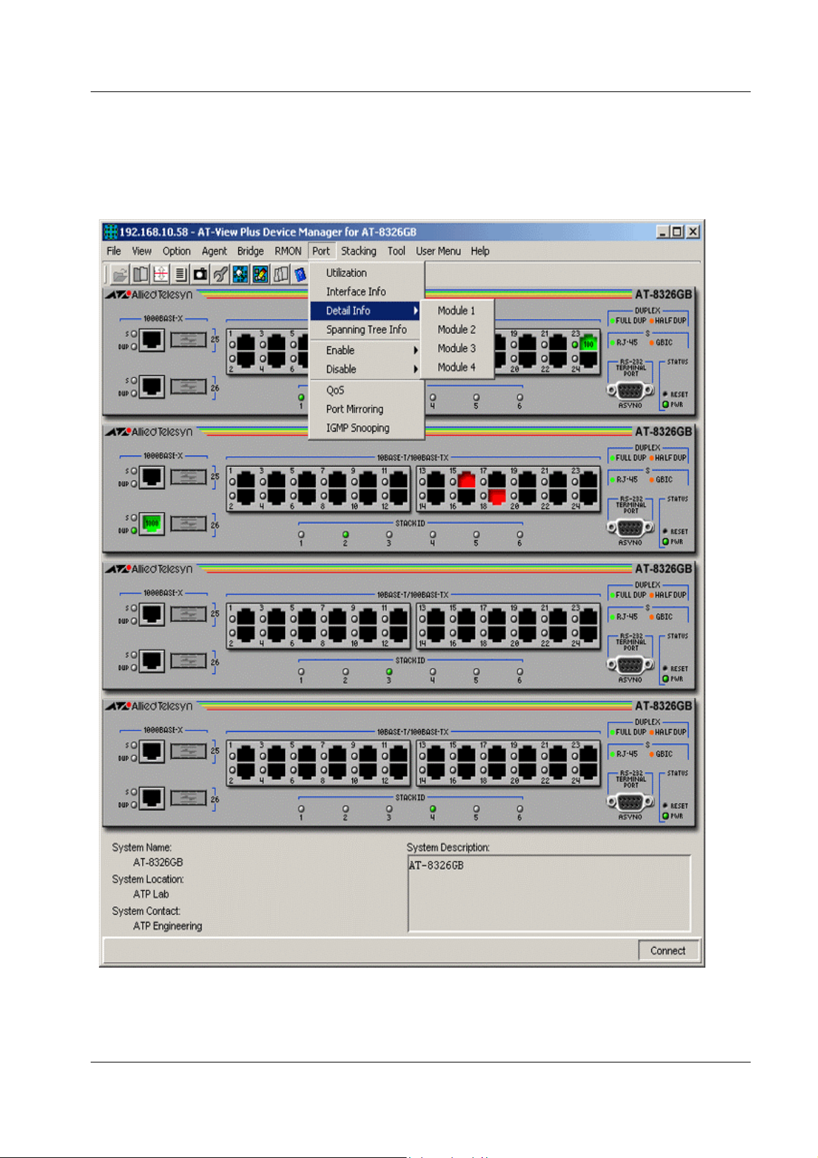
Menu for stacked devices
If the target is a stacked device, some menus have extra subitems to specify a single device in the
stack.
Module submenu
PN 613-50665-00 Rev B Page 13 of 277
Page 14
Allied Telesyn AT-VIEW PLUS
DEVICE MANAGEMENT
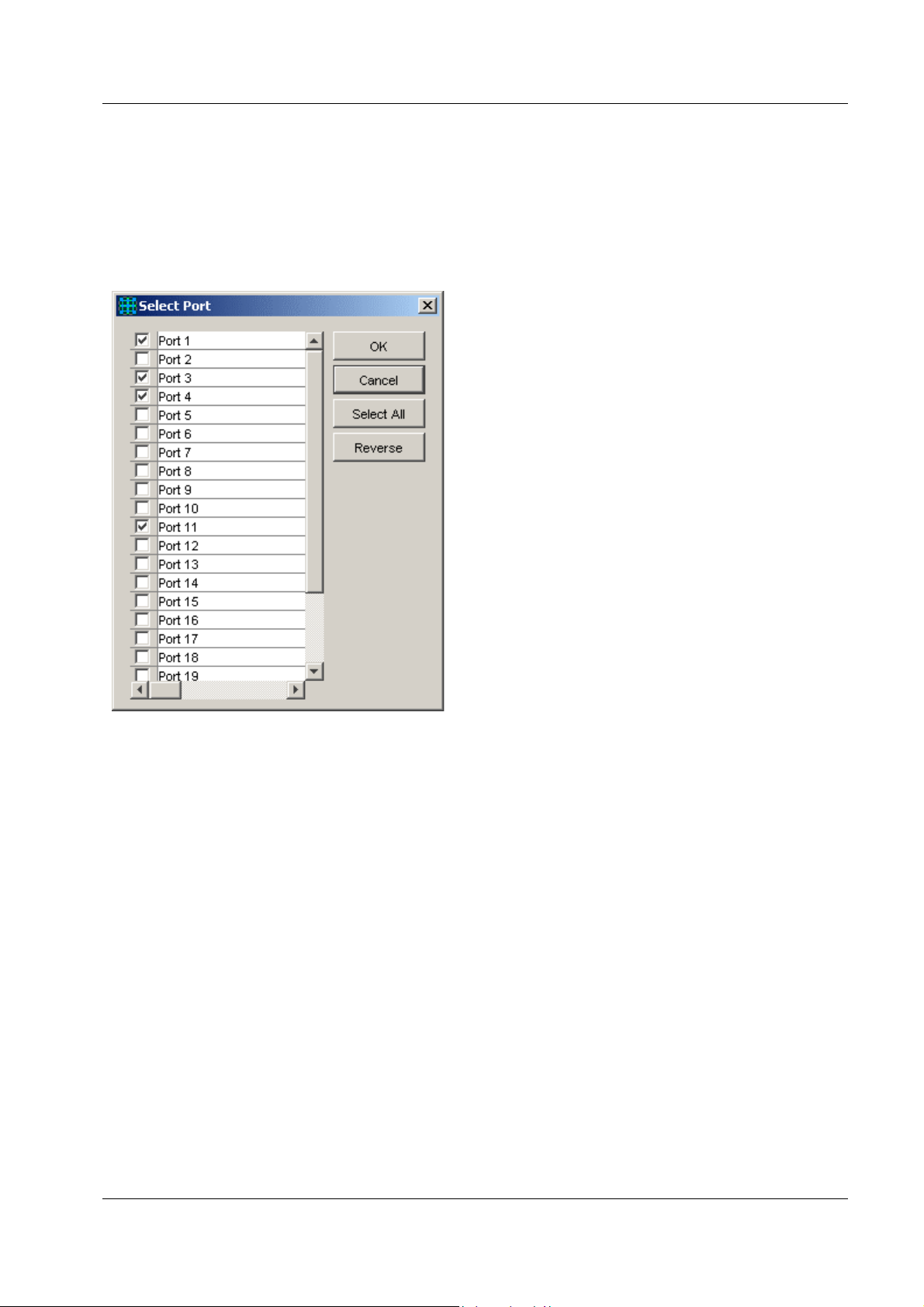
Port selection dialog box
When you select a menu item acting on ports, a dialog box opens to let you select ports. Check
the target ports and click OK.
Note - If you select multiple ports, it may take some time for data to be displayed.
Select Port dialog box
Port status colors
Port status is shown by its color. Port speed is also displayed in the port image.
• Link Up: Green
• Disabled: Red (the port is disabled by an administrator)
• Partitioned/Blocking: Yellow
• Others: Default color (usually black)
Note - SNMP v3: Depending on the READ VIEW access settings of the User Account Name
used, there is a possibility that AT-View Plus Device Manager may not be able to access some
MIB values that control the Port status. When this happens, the affected ports will be shown in
the default color.
PN 613-50665-00 Rev B Page 14 of 277
Page 15

Allied Telesyn AT-VIEW PLUS
DEVICE MANAGEMENT
LED status
In AT-View Plus Device Manager, LEDs do not blink. The meanings of LEDs differ between
devices.
Utilization
Utilization is calculated by the following formula.
# of frames x (96 + 64) + octets x 8
Utilization (%) = ------------------------------------------- x 100
Port speed (bps) x Sampling Interval(sec)
Device-Specific Menu Items
When using SNMPv3, some device-specific menu items may not be available (disabled)
depending on the READ VIEW access settings of the User Account Name used.
Basic Operations
PN 613-50665-00 Rev B Page 15 of 277
Page 16
Allied Telesyn AT-VIEW PLUS
DEVICE MANAGEMENT
AT-8000 Series
This section describes AT-View Plus Device Manager menus and operations specific to the AT8000 Series.
Topics:
• Main Window
• Agent Menu
• Bridge Menu
• RMON Menu
• Port Menu
• Stacking Menu
• Expansion Module Notes
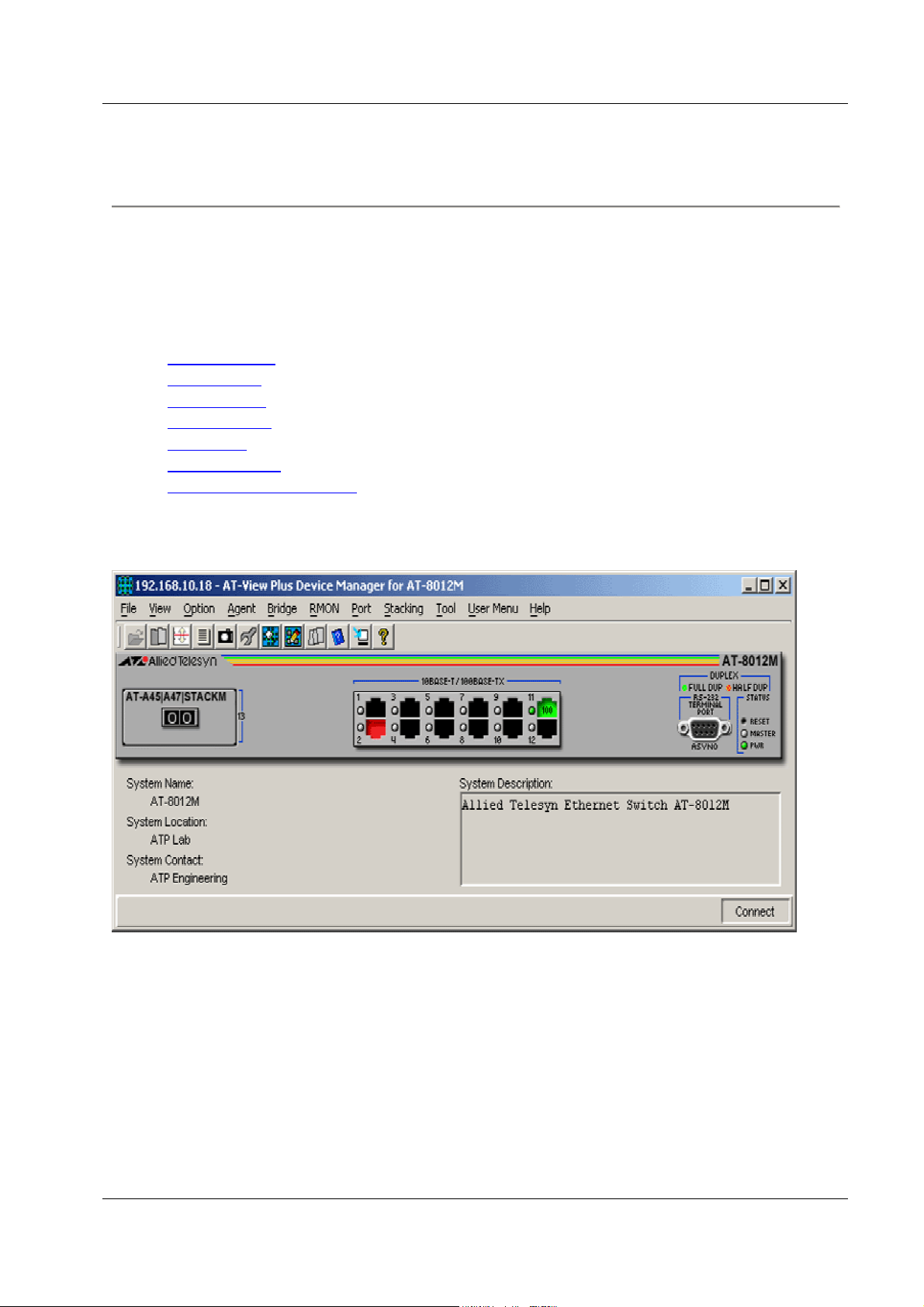
Main Window
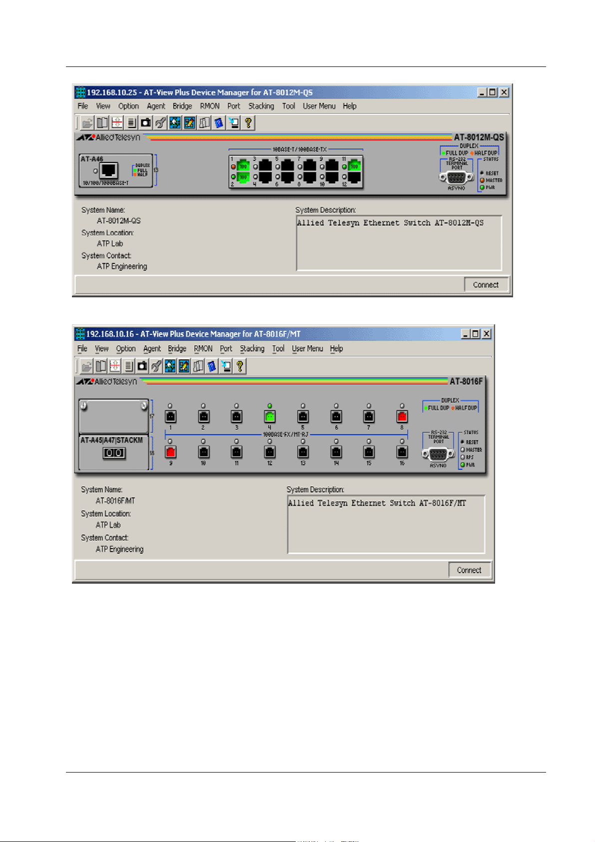
AT-8012M
PN 613-50665-00 Rev B Page 16 of 277
Page 17
Allied Telesyn AT-VIEW PLUS
DEVICE MANAGEMENT
AT-8012M-QS
AT-8016F/MT
PN 613-50665-00 Rev B Page 17 of 277
Page 18
Allied Telesyn AT-VIEW PLUS
DEVICE MANAGEMENT
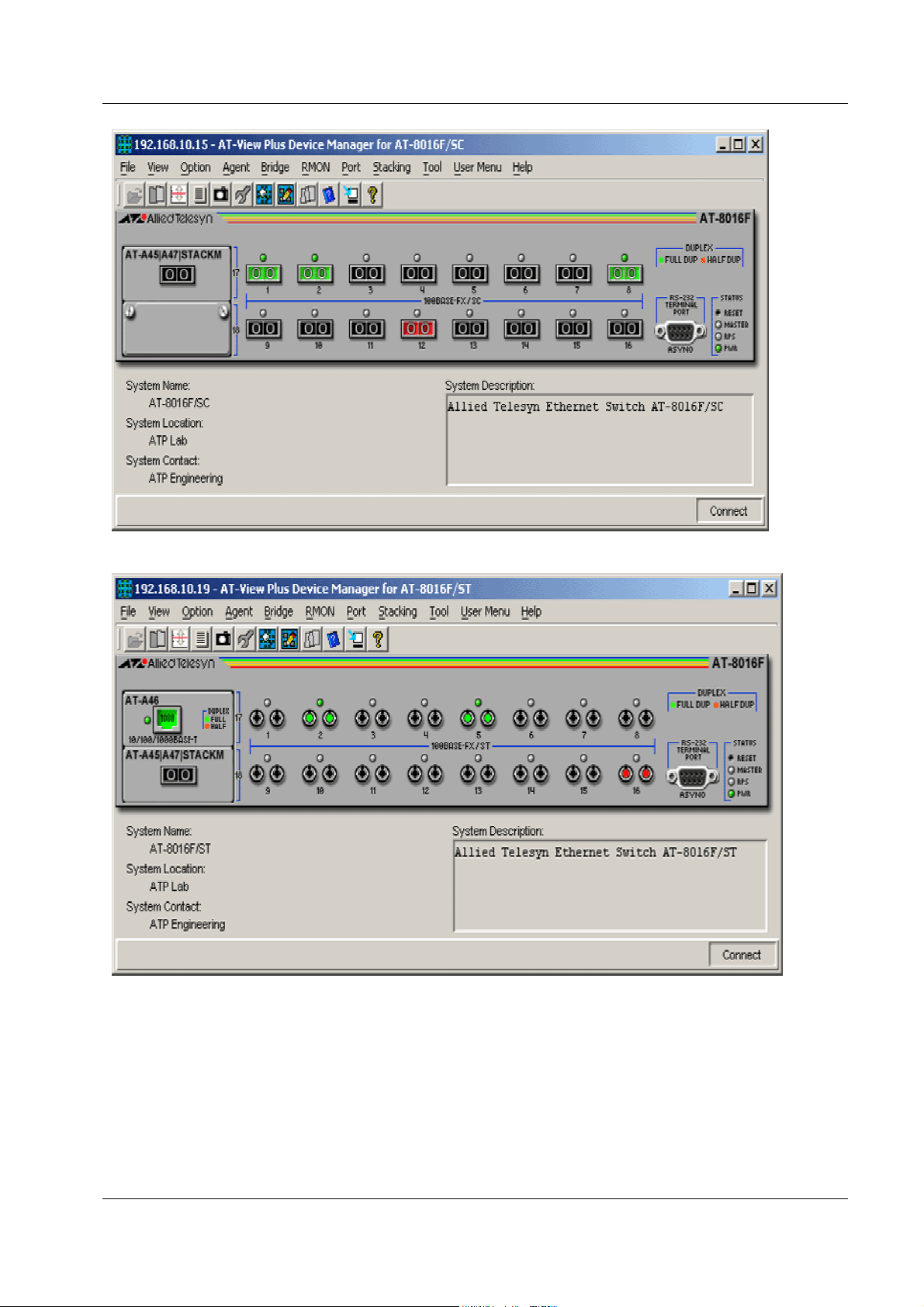
AT-8016F/SC
AT-8016F/ST
PN 613-50665-00 Rev B Page 18 of 277
Page 19
Allied Telesyn AT-VIEW PLUS
DEVICE MANAGEMENT
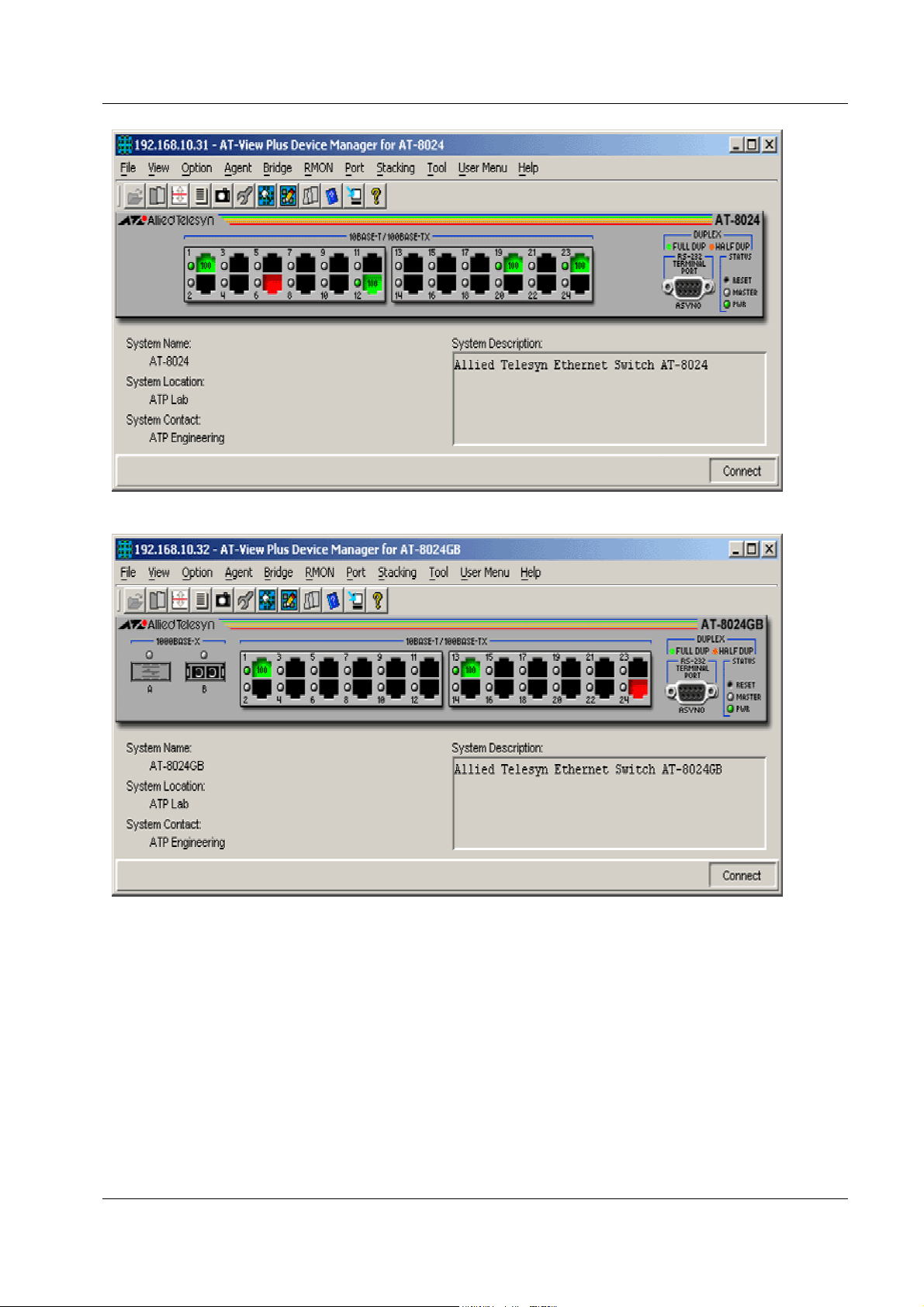
AT-8024
AT-8024GB
PN 613-50665-00 Rev B Page 19 of 277
Page 20
Allied Telesyn AT-VIEW PLUS
DEVICE MANAGEMENT
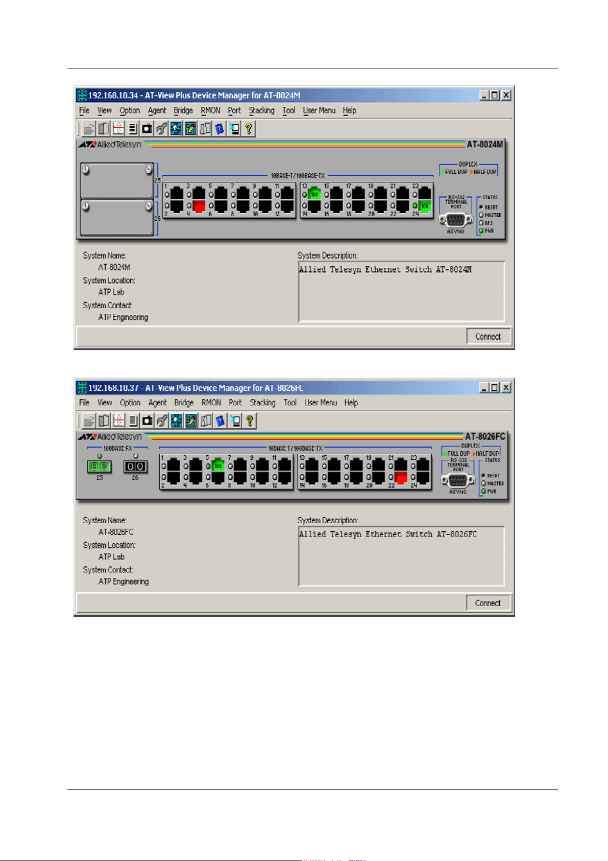
AT-8024M
AT-8026FC
PN 613-50665-00 Rev B Page 20 of 277
Page 21
Allied Telesyn AT-VIEW PLUS
DEVICE MANAGEMENT
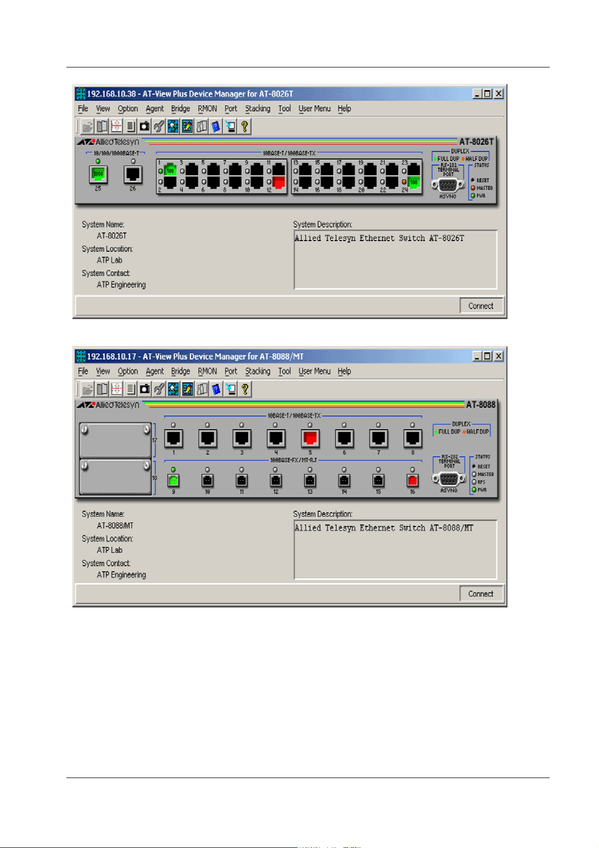
AT-8026T
AT-8088/MT
PN 613-50665-00 Rev B Page 21 of 277
Page 22
Allied Telesyn AT-VIEW PLUS
DEVICE MANAGEMENT
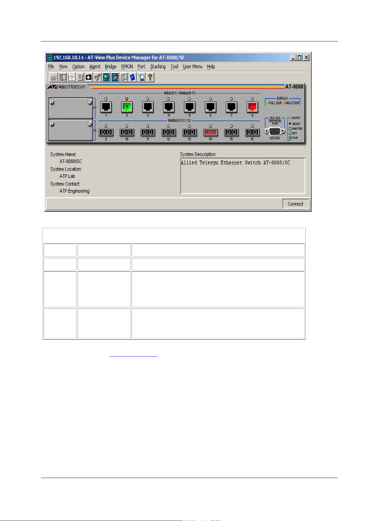
AT-8088/SC
Device Manager LEDs for AT-8000 Series
LED State Description
PWR Green The switch is receiving power.
MASTER Orange
The switch is the master switch of an enhanced stack.
Gray
The switch is a slave switch or is not a member of an
enhanced stack.
DUPLEX Green
Orange
The port is operating in full-duplex mode.
The port is operating in half-duplex mode.
Note - Please refer to Uplink Modules for the operations and behavior of the expansion modules
installed on these devices.
Note - The current firmware version does not allow AT-View Plus Device Manager to support
the RPS LED.
Note - When connecting to a slave switch, AT-View Plus Device Manager does not
automatically replace the master switch image in the main window with the slave switch image.
To view the slave switch image, click on the Refresh option under the Agent menu.
Note - AT-View Plus Device Manager will detect a loss of connection between an AT-8024GB
and an AT-9410GB when the uplink port on both devices are set to the same speed and mode.
Note - Connection between an AT-8024GB and an AT-8324 can only be established if the uplink
ports on both devices are configured to auto-negotiate.
PN 613-50665-00 Rev B Page 22 of 277
Page 23

Allied Telesyn AT-VIEW PLUS
DEVICE MANAGEMENT
Note - Setting the 'Active Protocol Version' to 'STP' and 'Spanning Tree Status' to 'enabled' will
set the Port State parameter of disabled ports to 'blocking'. As a result, port images for disabled
ports will turn yellow.
Note - Setting the 'Active Protocol Version' to 'RSTP' and 'Spanning Tree Status' to 'enabled' will
set the Port State parameter of inactive ports and disabled ports to 'blocking'. As a result, port
images for inactive ports and disabled ports will turn yellow.
Agent Menu
From the Agent menu, you can view and edit the system information for the device, or log into
the CLI using Telnet.
System Info
Displays basic system information, including system name, location, contact and
description.
Note - Attempting to set the System Contact, System Name, and System Location
parameters to NULL will result in a general error. However, the parameters will still be
temporarily set to NULL. Once the switch is restarted, the original values will be
restored.
Note - The current firmware version accepts up to 40 characters for the System Contact,
System Name and System Location parameters. However, specifying a value that is
exactly 40 characters in length will result in an error message. This error message may be
ignored as the value will still be set successfully.
Firmware Info
Displays firmware version.
Network Info
Displays network-related information such as the addresses of the default gateway and the
agents.
Note - The current firmware version does not allow the Default Domain Name and the
DNS Server parameters to be configured.
Manager Address Info
Displays the IP address of the management station.
Device Info
Displays general information about the switch.
MAC Address Table
Displays a list of static MAC addresses configured on the switch.
Note - MAC Address Table entries created through a local or telnet management session
will not be visible to AT-View Plus Device Manager until the device is restarted.
PN 613-50665-00 Rev B Page 23 of 277
Page 24

Allied Telesyn AT-VIEW PLUS
DEVICE MANAGEMENT
Reset
Resets the switch.
Telnet
Starts a Telnet connection to the switch.
WEB Browser
Connects to the switch's HTTP server.
Bridge Menu
From the Bridge menu, you can view and edit bridge information such as the forwarding
database and the spanning tree status.
Forwarding Database
Displays the Forwarding Database table.
Discard/Aging Time Info
Displays information about the number of address entries that were learned but discarded
because either there was a lack of memory or the entry's aging timer expired.
Note - The current firmware version accepts values in the range [10-1000000] inclusive
for the Aging Time parameter.
Spanning Tree Info
Displays spanning tree parameters such as priority and cost.
Note - The current firmware version accepts values in the range [0-65535] inclusive for
the Priority parameter regardless of the active spanning tree protocol version.
Statistics
Displays statistics about frames received/transmitted on the switch port.
RMON Menu
From the RMON menu you can view and edit the RMON MIB.
Statistics
Displays traffic statistics in the network segment attached to each port.
History Control Table
Displays the RMON History table.
Note - The current firmware version does not support the "historyControlTable" MIB
object of RFC1757. As a result, AT-View Plus Device Manager displays the error
message "Failed to get MIB data." when the History Control Table option is selected from
the RMON menu.
PN 613-50665-00 Rev B Page 24 of 277
Page 25

Allied Telesyn AT-VIEW PLUS
DEVICE MANAGEMENT
Alarm Table
Displays the RMON Alarm table.
Event Table
Displays the RMON Event table.
Event Log
Displays the RMON Event log.
Port Menu
From the Port menu, you can view and edit MIB information about the port.
Utilization
Displays the port's utilization information.
Interface Info
Displays port statistics such as the number of frames received and transmitted on the port,
bytes received and transmitted on the port, and port status.
Note - Valid MIB Set values for the Administration Status parameter are 'up' and 'down'.
Attempting to set this parameter to any other value will result in the error message: "The
error occurred with 'Set' operation. Error: bad value."
Error Statistics
Displays error statistics.
Detail Info
Displays detailed port information such as duplex mode.
Note - Setting the Port Reset parameter to 'reset' will not reset the port's attributes.
Note - Valid MIB Set values for the Port Flow Control parameter are 'disable', 'transmit-
only', 'receive-only', and 'transmit-and-receive'. However, the current firmware version
does not allow this parameter to be set to 'transmit-only' and 'receive-only' for the
following ports:
Expansion module ports •
•
GBIC ports on the AT-8024GB
•
Fiber optic ports on the AT-8026FC
•
10/100/1000Base-T ports on the AT-8026T
Note - Valid MIB Set values for the Port State parameter are 'enabled' and 'disabled'.
Attempting to set this parameter to any other value will result in the error message: "The
error occurred with 'Set' operation. Error: bad value."
PN 613-50665-00 Rev B Page 25 of 277
Page 26

Allied Telesyn AT-VIEW PLUS
DEVICE MANAGEMENT
Note - The current firmware version accepts up to 20 characters for the Port Name
parameter. Attempting to enter more than 20 characters will result in an error message
and may append additional characters to the input value.
Spanning Tree Info
Displays the port's spanning tree parameters.
Note - Setting a port's Port parameter to 'disabled' does not automatically set the Port
State parameter under Detail Info to 'disabled'. As a result, the port's image may not turn
red as expected.
Note - The current firmware version accepts values in the range [0-255] inclusive for the
Port Priority parameter regardless of the active spanning tree protocol version.
Note - The current firmware version accepts values in the range [0-65535] inclusive for
the Port Path Cost parameter regardless of the active spanning tree protocol version.
Enable
Enables the port.
Note - Under the Sun Solaris platform, the AT-View Plus Device Manager application
may terminate abnormally if multiple ports have been selected and each dialog box with
the message "May I set 'atiswitchPortState.n' to up" is clicked one after the other.
Disable
Disables the port.
Note - Under the Sun Solaris platform, the AT-View Plus Device Manager application
may terminate abnormally if multiple ports have been selected and each dialog box with
the message "May I set 'atiswitchPortState.n' to down" is clicked one after the other.
Port Mirroring
Displays port mirroring parameters and allows configuration of port mirroring state,
source, and destination.
Note - Valid MIB Set values for the Mirroring Destination Port parameter should range
from 0 to 24. However, the current firmware version allows the user to enter values up to
65535. Attempting to enter values greater than 65535 will cause the new value to be
converted to its equivalent wrap-around value; i.e., 65536 will become 0, 65537 will
become 1, and so on.
Note - The current firmware version does not allow the Port Mirroring Status parameter
to be set to 'receive' and 'transmit'. Attempting to do so will result in the error message:
"The error occurred with 'Set' operation. Error: bad value".
Note - By default, the Port Mirroring Status parameter is set to 'disabled' and the
Mirroring Destination Port parameter is set to 0. From this default state, the Port
Mirroring Status parameter can be set to 'both' successfully. However, to set the Port
PN 613-50665-00 Rev B Page 26 of 277
Page 27

Allied Telesyn AT-VIEW PLUS
DEVICE MANAGEMENT
Mirroring Status parameter back to 'disabled', the Mirroring Destination Port parameter
must be set to a non-zero value.
Note - Any change made to the Mirroring Source Ports parameter while the Mirroring
Destination Port parameter is set to 0 will take effect internally but will not be reflected in
the MIB variable window. To see the change reflected in the MIB variable window, the
Mirroring Destination Port parameter should be set to a non-zero value.
Stacking Menu
From the Stacking menu, you can perform enhanced stacking from any AT-8000 Series master
switch.
Stacking Info
Displays information about the switch's mode. This is also the menu where you can
perform enhanced stacking.
Note - For the Stack Switch Model parameter, additional characters appear after the
model name for discovered AT-8524M, AT-9424T/SP and AT-9424T/GB devices.
Expansion Module Notes
• AT-View Plus Device Manager cannot distinguish between the AT-A45/xx, AT-A47, and
AT-STACKM expansion modules. All are displayed with the same GIF image.
• When both the AT-A45 and AT-A46 expansion modules are present on a device, the AT-
A45 port image may show up as green and its Port Speed parameter may reflect the value
"1 Gbps" even if there is no connection established on the port. To reflect the correct port
image color and port speed, restart the device. This applies to the following devices:
AT-8016F/xx
AT-8024M
AT-8088/xx
• The Spanning Tree Protocol (STP) does not work for the AT-A46 expansion module
when it is installed on an AT-8016F/ST device. As a result, the Port State parameter of
the AT-A46 expansion module port will never be set to 'blocking' and the port image will
never turn yellow.
• Connection between an AT-A47 expansion module port that is configured to operate at
1Gbps full duplex and a port on another device can only be established if the port on the
other device is configured to auto-negotiate.
• For the AT-A47 expansion module, AT-View Plus Device Manager will only display the
AT-A45/AT-A47/AT-STACKM shared GIF image if a GBIC module is present in the
PN 613-50665-00 Rev B Page 27 of 277
Page 28

Allied Telesyn AT-VIEW PLUS
DEVICE MANAGEMENT
GBIC slot.
• By default, the Port Speed and Mode parameter of the AT-A47 expansion module port is
set to 'auto sense'. From this mode, the Port Speed and Mode can only be changed to
'1Gbps full-duplex'. However, once set to '1Gbps full-duplex', it can no longer be set to
'auto sense'.
AT-8000 Series
PN 613-50665-00 Rev B Page 28 of 277
Page 29
Allied Telesyn AT-VIEW PLUS
DEVICE MANAGEMENT
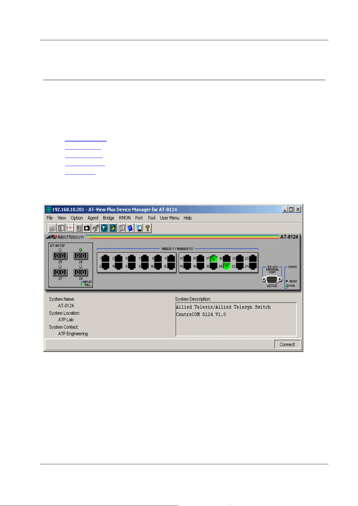
AT-8124
This section describes AT-View Plus Device Manager menus and operations specific to the AT8124 switch.
Topics:
• Main Window
• Agent Menu
• Bridge Menu
• RMON Menu
• Port Menu
Main Window
AT-8124
PN 613-50665-00 Rev B Page 29 of 277
Page 30

Allied Telesyn AT-VIEW PLUS
DEVICE MANAGEMENT
Device Manager LEDs for AT-8124
LED State Description
PWR Green The switch is receiving power.
DUPLEX Green
Gray
The port is operating in full-duplex mode.
The port is operating in half-duplex mode.
Agent Menu
From the Agent menu, you can view and edit the system information for the device or log into
the CLI using telnet.
System Info
Displays basic system information, including system name, location, contact and
description.
Network Info
Displays network-related information such as the device's IP address, and the default
gateway address.
Firmware Info
Displays the version of the software running on the managed device.
Manager Address Info
Displays the management station's IP address.
Reset
Resets the switch.
Hot Reset
Performs a software reset. This takes less time than a Cold Reset.
Cold Reset
Performs a hardware reset. This takes more time than a Hot Reset.
Telnet
Connects to the switch's Telnet service.
Bridge Menu
From the Bridge menu, you can view and edit bridge information such as the forwarding
database and the spanning tree status.
PN 613-50665-00 Rev B Page 30 of 277
Page 31

Allied Telesyn AT-VIEW PLUS
DEVICE MANAGEMENT
Forwarding Database
Displays the Forwarding Database table.
Discard/Aging Time Info
Displays information about the number of address entries that were learned but discarded
because either there was a lack of memory or the entry's aging timer expired.
Spanning Tree Info
Displays spanning tree parameters such as priority and cost.
Statistics
Displays statistics about frames received/transmitted on the switch port.
RMON Menu
From the RMON menu you can view and edit the RMON MIB.
Note - Since there may be a large quantity of RMON data, it may take some time for the
information to appear.
Statistics
Displays traffic statistics about the network segment attached to each port.
History Control Table
Displays the RMON History table.
Alarm Table
Displays the RMON Alarm table.
Event Table
Displays the RMON Event table.
Event Log
Displays the RMON Event log.
Port Menu
From the Port menu, you can view and edit MIB information about the port.
Utilization
Displays the port's utilization information.
Interface Info
Displays port statistics such as the number of frames received and transmitted on the port,
bytes received and transmitted on the port, and port status.
PN 613-50665-00 Rev B Page 31 of 277
Page 32

Allied Telesyn AT-VIEW PLUS
DEVICE MANAGEMENT
Detail Info
Displays port traffic statistics such as the number of frames received/transmitted on the
port.
Error Statistics
Displays error information.
Detail Status
Displays detailed port information such as duplex mode.
Spanning Tree Info
Displays the port's spanning tree parameters.
Enable
Enables the port.
Disable
Disables the port.
AT-8124
PN 613-50665-00 Rev B Page 32 of 277
Page 33

Allied Telesyn AT-VIEW PLUS
DEVICE MANAGEMENT
AT-8124XL (V2)
This section describes AT-View Plus Device Manager menus and operations specific to the AT8124XL (V2) switch.
Topics:
• Main Window
• Agent Menu
• Bridge Menu
• RMON Menu
• Port Menu
Main Window
AT-8124XL (V2)
Device Manager LEDs for AT-8124XL (V2)
LED State Description
PWR Green The switch is receiving power.
DUPLEX Green
Orange
The port is operating in full-duplex mode.
The port is operating in half-duplex mode.
PN 613-50665-00 Rev B Page 33 of 277
Page 34

Allied Telesyn AT-VIEW PLUS
DEVICE MANAGEMENT
Agent Menu
From the Agent menu, you can view and edit the system information for the device, or log into
the CLI using Telnet.
System Info
Displays basic system information, including system name, location, contact and
description.
Note - AT-View Plus Device Manager allows the user to enter up to 255 characters for
the System Contact, System Name, and System Location parameters but truncates them to
64 characters. NULL values are not accepted.
Firmware Info
Displays firmware version.
Network Info
Displays network-related information such as the addresses of the default gateway and the
agents.
DHCP Info
Displays DHCP information including the DHCP System Group and DHCP Timer
Group.
Manager Address Info
Displays the IP address of the management station.
Reset
Resets the switch.
Telnet
Starts a Telnet connection to the switch.
WEB Browser
Connects to the switch's HTTP server.
Bridge Menu
From the Bridge menu, you can view and edit bridge information such as the forwarding
database and the spanning tree status.
Forwarding Database
Displays the Forwarding Database table.
Discard/Aging Time Info
Displays information about the number of address entries that were learned but discarded
because either there was a lack of memory or the entry's aging timer expired.
PN 613-50665-00 Rev B Page 34 of 277
Page 35

Allied Telesyn AT-VIEW PLUS
DEVICE MANAGEMENT
Spanning Tree Info
Displays spanning tree parameters such as priority and cost.
Statistics
Displays statistics about frames received/transmitted on the switch's ports.
RMON Menu
From the RMON menu you can view and edit the RMON MIB.
Statistics
Displays traffic statistics in the network segment attached to each port.
History Control Table
Displays the RMON History table.
Alarm Table
Displays the RMON Alarm table.
Event Table
Displays the RMON Event table.
Event Log
Displays the RMON Event log.
Port Menu
From the Port menu, you can view and edit MIB information about the port.
Utilization
Displays the port's utilization information.
Interface Info
Displays port statistics such as the number of frames received and transmitted on the port,
bytes received and transmitted on the port, and port status.
Note - Valid MIB Set values for the Administration Status parameter are 'up' and 'down'.
All other values are ignored.
Detail Info
Displays detailed port information such as duplex mode.
Note - Enabling/Disabling the Port STP Configuration parameter for one port
enables/disables STP for all ports.
Note - Attempting to modify the Port Speed and Mode parameter from 'auto sense' to
'1Gbps half-duplex' or '1Gbps full-duplex' will result in the following:
PN 613-50665-00 Rev B Page 35 of 277
Page 36

Allied Telesyn AT-VIEW PLUS
DEVICE MANAGEMENT
• An error message: "The error occurred with 'Set' operation. Error: gen Error"
• Port Speed and Mode parameter value changing to '100Mbps half-duplex'
Note - The current firmware version does not allow the Port Bridge ID parameter to be
configured. Attempting to configure this parameter will result in the error message: "The
error occurred with 'Set' operation. Error: bad value."
Note - When a port is set to 'auto sense' and is connected to a half duplex port on another
device, its corresponding Duplex LED on the device image turns green instead of orange.
Note - The current firmware version does not allow the Port Back Pressure parameter to
be configured. Attempting to configure this parameter will result in the error message:
"The error occurred with 'Set' operation. Error: time out occurred."
Note - The Port Transmit Pacing Configuration parameter is not applicable to the AT-
8124XL (V2).
Note - The current firmware version does not allow the Port VLAN Tag Priority and the
Port QoS Priority parameters to be configured. Attempting to configure these parameters
will result in the error message: "The error occurred with 'Set' operation. Error: bad
value."
Note - Valid MIB Set values for the Port State parameter are 'enabled' and 'disabled'.
Attempting to set this parameter to any other value will result in the error message: "The
error occurred with 'Set' operation. Error: bad value.".
Spanning Tree Info
Displays the port's spanning tree parameters.
Enable
Enables the port.
Disable
Disables the port.
Port Mirroring
Displays port mirroring parameters and allows configuration of port mirroring state,
source, and destination.
IGMP Snooping
Displays the current state of IGMP Snooping and allows reconfiguration.
AT-8124XL (V2)
PN 613-50665-00 Rev B Page 36 of 277
Page 37

Allied Telesyn AT-VIEW PLUS
DEVICE MANAGEMENT
AT-8200XL Series
This section describes AT-View Plus Device Manager menus and operations specific to the AT8216FXL/SC and AT-8224XL switches.
Topics:
• Main Window
• Agent Menu
• Bridge Menu
• RMON Menu
• Port Menu
• Expansion Module Notes
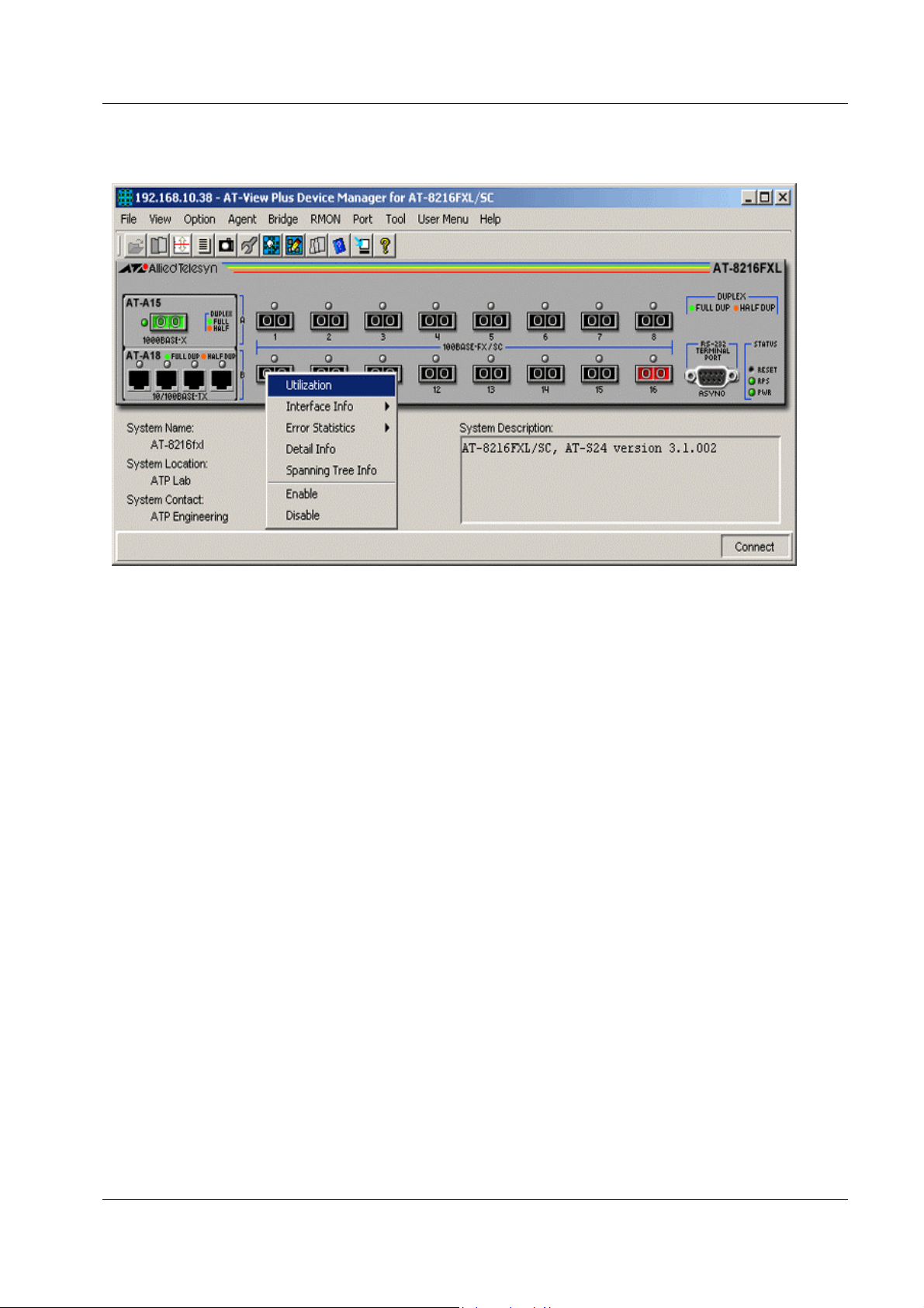
Main Window
AT-8216FXL/SC
PN 613-50665-00 Rev B Page 37 of 277
Page 38

Allied Telesyn AT-VIEW PLUS
DEVICE MANAGEMENT
AT-8224XL
Device Manager LEDs for AT-8200XL Series
LED State Description
PWR Green The switch is receiving power.
RPS
DUPLEX Green
Green
Gray
Orange
An optional redundant power supply is connected to the switch.
There is no redundant power supply connected to the switch.
The port is operating at full-duplex mode.
The port is operating at half-duplex mode.
Note - Please refer to Uplink Modules for the operations and behavior of the expansion modules
installed on these devices.
Agent Menu
From the Agent menu, you can view and edit the system information for the device, or log into
the CLI using Telnet.
System Info
Displays basic system information, including system name, location, contact and
description.
Note - The current firmware version allows the user to enter up to 64 characters for the
System Contact and the System Location parameters and up to 20 characters for the
System Name parameter.
PN 613-50665-00 Rev B Page 38 of 277
Page 39

Allied Telesyn AT-VIEW PLUS
DEVICE MANAGEMENT
Note - The current firmware version appends a period '.' and the value of the Default
Domain Name parameter to the value of the System Name parameter.
Firmware Info
Displays the firmware version of the switch.
Network Info
Displays network-related information such as the addresses of the default gateway and the
agents.
Manager Address Info
Displays the IP address of the management station.
Device Info
Displays general information about the switch.
Note - The Security Action parameter has a fixed value of 'do nothing' and cannot be
modified.
Note - The Security Configuration parameter has a fixed value of 'disabled' and cannot be
modified.
Note - Valid MIB Set values for the HOL Configuration and Logging Configuration
parameters are 'on' and 'off'. Attempting to set these parameters to any other value will
result in the error message: "The error occurred with 'Set' operation. Error: bad value".
Note - Valid MIB Set values for the QoS Configuration parameter are:
• mode 1
• mode 2
• mode 3
• mode 4
• mode 5
• mode 6
• mode 7
• mode 8
Attempting to set this parameter to any other value will result in the error message: "The
error occurred with 'Set' operation. Error: bad value".
DHCP Info
Displays the DHCP information about the switch.
Diagnostics
Displays the operating status of the switch's components such as power supply and
system fans.
Note - The current firmware version returns 'non-supported' for the following parameters:
PN 613-50665-00 Rev B Page 39 of 277
Page 40

Allied Telesyn AT-VIEW PLUS
DEVICE MANAGEMENT
• Fan Speed 3
• 3.3V Power
• 2.5Va Power
• 2.5Vb Power
• 2V Power
• CPU Temperature
Reset
Resets the switch.
Console Settings
Displays the current settings of the console.
Telnet
Starts a Telnet connection to the switch.
WEB Browser
Connects to the switch's HTTP server.
Note - The current firmware version is unable to display the AT-8216FXL/SC device
image in the Omega web management session interface.
Bridge Menu
From the Bridge menu, you can view and edit bridge information such as the forwarding
database and the spanning tree status.
Bridge Info
Displays basic bridge information such as the LAN ID, bridge address, number of parts
controlled by the bridging entity and the bridge type.
Forwarding Database
Displays the Forwarding Database table.
Note - The current firmware version does not allow the VLAN Name parameter to be
configured. Attempting to configure this parameter will result in the error message: "The
error occurred with 'Set' operation. Error: noSuchName."
Discard/Aging Time Info
Displays information about the number of address entries that were learned but discarded
because either there was a lack of memory or the entry's aging timer expired.
Spanning Tree Info
Displays spanning tree parameters such as priority and cost.
Statistics
Displays statistics about frames received/transmitted on the switch port.
PN 613-50665-00 Rev B Page 40 of 277
Page 41

Allied Telesyn AT-VIEW PLUS
DEVICE MANAGEMENT
RMON Menu
From the RMON menu you can view and edit the RMON MIB.
Statistics
Displays traffic statistics in the network segment attached to each port.
History Control Table
Displays the RMON History table.
Alarm Table
Displays the RMON Alarm table.
Event Table
Displays the RMON Event table.
Event Log
Displays the RMON Event log.
Port Menu
From the Port menu, you can view and edit MIB information about the port.
Utilization
Displays the port's utilization information.
Interface Info
Displays port statistics such as the number of frames received and transmitted on the port,
bytes received and transmitted on the port, and port status.
Note - Valid MIB Set values for the Administration Status parameter are 'up' and 'down'.
Attempting to set this parameter to any other value will result in the error message: "The
error occurred with 'Set' operation. Error: bad value."
Error Statistics
Displays error statistics.
Detail Info
Displays detailed port information such as duplex mode.
Note - The Port Flow Control parameter has a fixed value of 'not supported' and cannot be
modified.
Note - When the Port Speed and Mode parameter of an AT-8224XL fixed port is set to
'auto sense' and the port is connected to a full duplex port on another device, its
corresponding Duplex LED on the device image turns orange instead of green.
PN 613-50665-00 Rev B Page 41 of 277
Page 42

Allied Telesyn AT-VIEW PLUS
DEVICE MANAGEMENT
Note - The current firmware version allows active ports to be disabled. However, the
disabled ports' Port Link State parameter retains the value 'on-line'.
Note - Valid MIB Set values for the Port State parameter are 'enabled' and 'disabled'.
Attempting to set this parameter to any other value will result in the error message: "The
error occurred with 'Set' operation. Error: bad value."
Note - Attempting to configure the Port Speed and Mode parameter of an AT-
8216FXL/SC fixed port to '10Mbps half-duplex' or '10Mbps full-duplex' will
automatically set it to '100Mbps half-duplex' or '100Mbps full-duplex' respectively.
Note - The following parameters are not applicable to the AT-8200XL Series:
• Port Transmit Pacing Configuration
• Port MDI Configuration
• Port VDSL Rate Configuration
• Port VDSL Link Mode
Spanning Tree Info
Displays the port's spanning tree parameters.
Enable
Enables the port.
Disable
Disables the port.
Port Mirroring
Displays the information about port mirroring.
PN 613-50665-00 Rev B Page 42 of 277
Page 43

Allied Telesyn AT-VIEW PLUS
DEVICE MANAGEMENT
Expansion Module Notes
• When the Port Speed and Mode parameter of an AT-A14 expansion module port is set to
'auto sense' and the port is connected to a 100Mbps full duplex port on another device, its
corresponding Duplex LED on the device image turns orange instead of green.
• The current firmware version does not allow the Port Speed and Mode parameter of the
AT-A14 expansion module port to be set to any value other than 'auto-sense'.
• A GBIC image is always visible on the GBIC slot of the AT-A15 expansion module
image even if there is no GBIC physically present in the slot.
• The Port Speed and Mode parameter of an AT-A15 expansion module port must match
the duplex mode of the port to which it is connected in order to establish connection.
• The current firmware version does not allow AT-View Plus Device Manager to
distinguish the AT-A16, AT-A17, and AT-A19 expansion modules from each other. With
the connector type (VF-45, SC, MT-RJ) being the only difference among them, all three
expansion modules have been made to share the same GIF image.
• Attempting to configure the Port Speed and Mode parameter of an AT-A16/AT-A17/AT-
A19 expansion module port to '10Mbps half-duplex' or '10Mbps full-duplex' will
automatically set it to '100Mbps half-duplex' or '100Mbps full-duplex' respectively.
• The current firmware version does not allow the Port Speed and Mode parameter of the
AT-A17 expansion module ports to be set to 'auto sense'.
• When the Port Speed and Mode parameter of an AT-A18 expansion module port is set to
'auto sense' and the port is connected to a full duplex port on another device, its
corresponding Duplex LED on the device image turns orange instead of green.
AT-8200XL Series
PN 613-50665-00 Rev B Page 43 of 277
Page 44

Allied Telesyn AT-VIEW PLUS
DEVICE MANAGEMENT
AT-8324
This section describes AT-View Plus Device Manager menus and operations specific to the AT8324 switch.
Topics:
• Main Window
• Agent Menu
• Bridge Menu
• RMON Menu
• Port Menu
• Expansion Module Notes
Main Window
AT-8324
Supports up to 8 stacked AT-8324 switches.
PN 613-50665-00 Rev B Page 44 of 277
Page 45

Allied Telesyn AT-VIEW PLUS
DEVICE MANAGEMENT
Device Manager LEDs for AT-8324
LED State Description
PWR Green The switch is receiving power.
DUPLEX Green
Orange
The port is operating in full-duplex mode.
The port is operating in half-duplex mode.
Note - Please refer to Uplink Modules for the operations and behaviour of the expansion modules
installed on these devices.
Note - The current firmware version does not allow AT-View Plus Device Manager to support
the RPS and MASTER LEDs.
Note - When a port is configured to auto-negotiate, the current firmware version does not always
update its Port Duplex Status parameter with the correct negotiated mode. As a result, the port's
Duplex LED may show up as green when it should really be orange and vice-versa.
Agent Menu
From the Agent menu, you can view and edit the system information for the device, or log into
the CLI using Telnet.
System Info
Displays basic system information, including system name, location, contact and
description.
Note - Attempting to enter more than 39 characters for the System Contact, System
Name, and System Location parameters will result in the error message: "The error
occurred with 'Set' operation. Error: gen Error".
Firmware Info
Displays firmware version.
Network Info
Displays network-related information such as the addresses of the default gateway and the
agents.
Manager Address Info
Displays the IP address of the management station.
Device Info
Displays information of the device such as Product Type, Port Count and Uplink Types
for all switches in the stack.
Reset
Resets the switch.
PN 613-50665-00 Rev B Page 45 of 277
Page 46

Allied Telesyn AT-VIEW PLUS
DEVICE MANAGEMENT
Telnet
Starts a Telnet connection to the switch.
WEB Browser
Connects to the switch's HTTP server.
Bridge Menu
From the Bridge menu, you can view and edit bridge information such as the forwarding
database and the spanning tree status.
Forwarding Database
Displays the Forwarding Database table.
Discard/Aging Time Info
Displays information about the number of address entries that were learned but discarded
because of lack memory or the entry's aging timer has expired.
Note - The current firmware version accepts values in the range [8-512] inclusive for the
Aging Time parameter. However, if the value entered is not a multiple of 8, the firmware
will convert it to the largest multiple of 8 less than the entered value.
Spanning Tree Info
Displays spanning tree parameters such as priority and cost.
Note - When STP/RSTP is enabled, the current firmware version sets the Port State
parameter of all inactive ports to 'blocking'. As a result, inactive ports will turn yellow in
AT-View Plus Device Manager.
Note - When enabling/disabling STP/RSTP, connection to the AT-8324 is temporarily
lost. As a result, the following error message appears: "The error occurred with 'Set'
operation. Error: time out occurred." This will not affect the application in any way.
Statistics
Displays statistics about frames received/transmitted on the switch's ports.
RMON Menu
From the RMON menu you can view and edit the RMON MIB.
Statistics
Displays traffic statistics in the network segment attached to each port.
History Control Table
Displays the RMON History table.
PN 613-50665-00 Rev B Page 46 of 277
Page 47

Allied Telesyn AT-VIEW PLUS
DEVICE MANAGEMENT
Note - The current firmware version is unable to retrieve the correct information for the
History Control Table. As a result, the following error message appears: "Failed to get
MIB data."
Alarm Table
Displays the RMON Alarm table.
Event Table
Displays the RMON Event table.
Event Log
Displays the RMON Event log.
Port Menu
From the Port menu, you can view and edit MIB information about the port.
Note - The current firmware version does not allow AT-View Plus Device Manager to support
the following features:
• Spanning Tree Info
• Class of Service
• IGMP Snooping
Utilization
Displays the port's utilization information.
Interface Info
Displays port statistics such as the number of frames received and transmitted on the port,
bytes received and transmitted on the port, and port status.
Note - The Port Type parameter returns '???(62)'.
Note - Valid MIB Set values for the Administration Status parameter are 'up' and 'down'.
Attempting to set this parameter to any other value will result in the error message: "The
error occurred with 'Set' operation. Error: gen Error."
Error Statistics
Displays error statistics.
Detail Info
Displays detailed port information such as duplex mode.
Note - The current firmware version accepts from 0 up to 19 characters for the Port Name
parameter.
PN 613-50665-00 Rev B Page 47 of 277
Page 48

Allied Telesyn AT-VIEW PLUS
DEVICE MANAGEMENT
Note - The current firmware version (AT-S25 v2.0.2) supports atiStackSwitch.mib v1.0.
However, AT-View Plus Device Manager supports atiStackSwitch.mib v2.10. As a result,
the following additional port parameters will appear:
• Port MDIO
• Port HOL Limit
• Port Back Pressure Limit
• Port STP State
These parameters are defined in v2.10 but will return 'noSuchName.' because they do not
exist in v1.0.
Note - The current firmware version does not allow the Port State parameter to be set to
'enabled'. Attempting to do so will result in the error message: "The error occurred with
'Set' operation. Error: bad value." To enable a port, click on the Enable option under the
Port menu.
Note - 4 ports are allotted for each expansion module slot. This means that ports on
expansion modules will always be numbered starting from 25 if inserted in Slot A and
from 29 if inserted in Slot B. As a result, the Detail Info MIB variable window for port
numbers that do not have corresponding physical ports on the expansion module inserted
will display 'noSuchName.' for all parameters.
Enable
Enables the port.
Note - The current firmware version (AT-S25 v2.0.2) supports atiStackSwitch.mib v1.0
while AT-View Plus Device Manager supports atiStackSwitch.mib v2.10. In v1.0, the
Port State parameter has 6 possible states with the enabled state having an ordinal value
of 3. In v2.10, the Port State parameter has only 2 possible states with the enabled state
having an ordinal value of 1. Since AT-View Plus Device Manager continues to use the
ordinal value 3, which does not exist in v2.10, the confirmation message will appear as
"May I set up 'atiStkSwPortState.x.y' to '???(3)'?" However, clicking on the OK button
will still enable the port successfully. This is because the actual Set operation is
performed on the device whose firmware supports v1.0 and thus, recognizes the ordinal
value 3.
Disable
Disables the port.
Port Mirroring
Displays port mirroring parameters and allows configuration of port mirroring state,
source, and destination.
PN 613-50665-00 Rev B Page 48 of 277
Page 49

Allied Telesyn AT-VIEW PLUS
DEVICE MANAGEMENT
Expansion Module Notes
Displays basic expansion information.
Note - Expansion module ports cannot be enabled/disabled. Attempting to do so will
result in the error message: "The error occurred with 'Set' operation. Error: gen Error".
Note - The Port Speed and Mode parameter of the 100/1000Base-T port on the AT-A14
expansion module can only be set to 'auto'. Attempting to set this to any other value will
result in the error message: "The error occurred with 'Set' operation. Error: gen Error".
Note - A GBIC image is always visible on the GBIC slot of the AT-A15 expansion
module even if there is no GBIC physically inserted.
Note - The Port Speed and Mode parameter of the 1000Base-X port on the AT-A15
expansion module can only be set to '1Gbps full-duplex'. Attempting to set this to any
other value will result in the error message: "The error occurred with 'Set' operation.
Error: gen Error".
Note - The Port Speed and Mode parameter of the 100Base-FX port on the AT-A16, AT-
A17, and AT-A19 expansion modules can only be set to '100Mbps full-duplex'.
Attempting to set this to any other value will result in the error message: "The error
occurred with 'Set' operation. Error: gen Error".
AT-8324
PN 613-50665-00 Rev B Page 49 of 277
Page 50

Allied Telesyn AT-VIEW PLUS
DEVICE MANAGEMENT
AT-8324SX
This section describes AT-View Plus Device Manager menus and operations specific to the AT8324SX switch.
Topics:
• Main Window
• Agent Menu
• Bridge Menu
• RMON Menu
• Port Menu
• Stacking Menu
PN 613-50665-00 Rev B Page 50 of 277
Page 51

Allied Telesyn AT-VIEW PLUS
DEVICE MANAGEMENT
Main Window
AT-8324SX
Supports up to 4 stacked switches.
PN 613-50665-00 Rev B Page 51 of 277
Page 52

Allied Telesyn AT-VIEW PLUS
DEVICE MANAGEMENT
Device Manager LEDs for AT-8324SX
LED State Description
PWR Green The switch is receiving power.
RPS
DUPLEX
STACK
Green
Gray
Gray
Orange
Redundant power is ON.
Redundant power is OFF.
The port is operating in full-duplex mode.
The port is operating in half-duplex mode.
Green The switch's position in the switch stack.
ID
Note - When multiple units of AT-8324SX are stacked together, port numbering is continuous.
This means that the first unit on the stack will have ports numbered from 1 to 32. The second unit
on the stack will have ports numbered from 33 to 64. The third unit will have ports numbered
from 65 to 96 and the fourth unit from 97 to 128. It is assumed that the maximum number of
ports per unit is 32, 24 fixed ports plus up to 8 uplink ports.
Agent Menu
From the Agent menu, you can view and edit the system information for the switch, or log into
the CLI using Telnet.
System Info
Displays basic system information, including system name, location, contact and
description.
Note - AT-View Plus Device Manager allows the user to enter up to 255 characters for
the System Contact, System Name, and System Location parameters.
TFTP Download Management
Displays TFTP information.
Note - AT-View Plus Device Manager allows the user to enter up to 80 characters for the
TFTP File Name parameter but truncates it to 47 characters.
Note - AT-View Plus Device Manager does not allow the user to set the Download Mode
parameter to 'temporary'. Attempting to do so will result in the error message: "The error
occurred with 'Set' operation. Error: bad value."
Reset
Displays the reset table that allows you to configure reset parameters before restarting the
management agent.
Telnet
Starts a Telnet connection to the switch.
PN 613-50665-00 Rev B Page 52 of 277
Page 53

Allied Telesyn AT-VIEW PLUS
DEVICE MANAGEMENT
WEB Browser
Connects to the switch's HTTP server.
Bridge Menu
From the Bridge menu, you can view and edit bridge information, such as the forwarding
database and spanning tree status.
Forwarding Database
Displays the Forwarding Database table.
Discard/Aging Time Info
Displays information about the number of address entries that were learned but discarded
because either there was a lack of memory or the entry's aging timer expired.
Note - Valid MIB Set values for the Aging Time parameter should range from 10 to 412.
However, the current firmware version allows it to be set to a value greater than 412 all
the way up to 1000000.
Spanning Tree Info
Displays spanning tree parameters such as priority and cost.
Statistics
Displays statistics about frames received/transmitted on the switch's ports.
RMON Menu
From the RMON menu, you can view and edit the RMON mib.
Statistics
Displays traffic statistics in the network segment attached to each port.
History Control Table
Displays the RMON history table.
Alarm Table
Displays the RMON alarm table.
Event Table
Displays the RMON event table.
Event Log
Displays the RMON event log.
PN 613-50665-00 Rev B Page 53 of 277
Page 54

Allied Telesyn AT-VIEW PLUS
DEVICE MANAGEMENT
Port Menu
From the Port menu, you can view and edit MIB information about the port.
Note - The current firmware version does not allow Port Menu to support the Class of Service.
Utilization
Displays the port's utilization information.
Interface Info
Displays port statistics such as the number of frames received and transmitted on the port,
bytes received and transmitted on the port, and port status.
Note - Valid MIB Set values for the Administration Status parameter are 'up' and 'down'.
Attempting to set this parameter to any other value will result in the following error
message: "The error occurred with 'Set' operation. Error: bad value." This will not affect
the application in any way.
Error Statistics
Displays error statistics.
Detail Info
Displays detailed port information such as duplex mode.
Note - The current firmware version does not support port naming.
Note - When the Port Speed and Mode parameter of a fixed port is set to 'auto sense', the
current firmware version is unable to provide information on the negotiated mode of the
port. As a result, the port's Duplex LED may show up as green when it should really be
orange and vice-versa.
Note - Valid MIB Set values for the Port Speed and Mode parameter of the AT-B17
expansion module ports are '100Mbps full-duplex' or '100Mbps half-duplex'. Attempting
to set this to any other value will result in the error message: "The error occurred with
'Set' operation. Error: bad value".
Note - Valid MIB Set values for the Port Speed and Mode parameter of the AT-B15
expansion module port are 'auto sense', '1Gbps full-duplex' or '1Gbps half-duplex'.
Attempting to set this to any other value will result in the error message: "The error
occurred with 'Set' operation. Error: bad value".
Note - The Module ID and Port Number parameters return 'noSuchName'.
Spanning Tree Info
Displays the port's spanning tree parameters.
Enable
Enables the port.
PN 613-50665-00 Rev B Page 54 of 277
Page 55

Allied Telesyn AT-VIEW PLUS
DEVICE MANAGEMENT
Disable
Disables the port.
Port Mirroring
Displays port mirroring parameters and allows configuration of port mirroring state,
source, and destination.
IGMP Snooping
Displays the current state of IGMP Snooping and allows reconfiguration.
Note - Valid MIB Set values for the IGMP Report Delay parameter should range from 5
to 30. However, the current firmware version does not allow it to be set to a value greater
than 10. Attempting to do so will result in the error message: "The error occurred with
'Set' operation. Error: bad value."
Stacking Menu
From the Stacking menu, you can view basic switch information as well as stacking information.
Stacking Info
Displays information such as Hardware Version, Firmware Version, Expansion Slot, and
Role In System for all switches in the stack.
AT-8324SX
PN 613-50665-00 Rev B Page 55 of 277
Page 56

Allied Telesyn AT-VIEW PLUS
DEVICE MANAGEMENT
AT-8300GB Series
This section describes AT-View Plus Device Manager menus and operations specific to the AT8300GB Series.
Topics:
• Main Window
• Agent Menu
• Bridge Menu
• RMON Menu
• Port Menu
• Stacking Menu
PN 613-50665-00 Rev B Page 56 of 277
Page 57

Allied Telesyn AT-VIEW PLUS
DEVICE MANAGEMENT
Main Window
AT-8326GB
The AT-8326GB supports up to 6 AT-8326GB stacked switches or any of the following mixed
stack combinations of AT-8326GB and AT-8350GB switches:
PN 613-50665-00 Rev B Page 57 of 277
Page 58

Allied Telesyn AT-VIEW PLUS
DEVICE MANAGEMENT
• Two AT-8326GB switches and one AT-8350GB switch
• Two AT-8326GB switches and two AT-8350GB switches
• Three AT-8326GB switches and one AT-8350GB switch
• Four AT-8326GB switches and one AT-8350GB switch
Note - When 3 or more AT-8326GB devices are stacked together, expect the twisted pair port
image of Port 26 on the last device on the stack to turn green. This is because the current
firmware version returns 'on-line' for the Port Link State parameter of the port even if there is no
link established.
AT-8350GB
The AT-8350GB supports up to 3 stacked AT-8350GB switches.
Note - The current firmware version does not allow AT-View Plus Device Manager to support
the RPS LED.
Note - The current firmware version does not allow AT-View Plus Device Manager to support
expansion modules that may be installed on the AT-8350GB.
PN 613-50665-00 Rev B Page 58 of 277
Page 59

Allied Telesyn AT-VIEW PLUS
DEVICE MANAGEMENT
Device Manager LEDs for AT-8300GB Series
LED State Description
PWR Green The switch is receiving power.
STACK ID Green The switch's position in the switch stack.
DUPLEX
Green
Orange
The port is operating in full-duplex mode.
The port is operating in half-duplex mode.
Note - Status information for the gigabit ports will always be reflected on the RJ-45 gigabit port
images regardless of whether the gigabit ports have been set to operate as GBIC ports or as
Twisted Pair ports.
Note - When Global STP is enabled, the current firmware version sets the Port State parameter of
inactive ports to 'blocking'. As a result, expect port images for inactive ports to turn yellow in
AT-View Plus Device Manager .
Note - The current firmware version does not allow AT-View Plus Device Manager to detect the
presence or absence of a GBIC module in any of the GBIC slots. As a result, the GBIC slots on
the device image will remain empty regardless of whether or not GBIC modules are physically
present in the slots.
Agent Menu
From the Agent menu, you can view and edit the system information for the device, or log into
the CLI using Telnet.
System Info
Displays basic system information, including system name, location, contact and
description.
Note - The current firmware version does not allow multiple-word values for the System
Name parameter.
Note - AT-View Plus Device Manager allows the user to enter up to 255 characters for
the System Contact, System Name and System Location parameters but the current
firmware version truncates them to 64 characters.
Firmware Info
Displays the version of the software running on the managed device.
Network Info
Displays network-related information such as the device IP address and the default
gateway address.
Note - The current firmware version does not save changes made to the DNS Server and
the Default Domain Name parameters.
PN 613-50665-00 Rev B Page 59 of 277
Page 60

Allied Telesyn AT-VIEW PLUS
DEVICE MANAGEMENT
DHCP Info
Displays DHCP information including the DHCP System Group and DHCP Timer
Group.
Manager Address Info
Displays the IP address of the management station.
Reset
Resets the switch.
Telnet
Starts a Telnet connection to the switch.
WEB Browser
Connects to the switch's HTTP server.
Bridge Menu
From the Bridge menu, you can view and edit bridge information such as the forwarding
database and the spanning tree status.
Forwarding Database
Displays the Forwarding Database table.
Discard/Aging Time Info
Displays information about the number of address entries that were learned but discarded
because of lack of memory or the entry's aging timer has expired.
Note - The current firmware version accepts values in the range [10-1000000] inclusive
for the Aging Time parameter.
Spanning Tree Info
Displays spanning tree parameters such as priority and cost.
Statistics
Displays statistics about frames received/transmitted on the switch's ports.
RMON Menu
From the RMON menu you can view and edit the RMON MIB.
Statistics
Displays traffic statistics in the network segment attached to each port.
History Control Table
Displays the RMON History table.
PN 613-50665-00 Rev B Page 60 of 277
Page 61

Allied Telesyn AT-VIEW PLUS
DEVICE MANAGEMENT
Alarm Table
Displays the RMON Alarm table.
Event Table
Displays the RMON Event table.
Event Log
Displays the RMON Event log.
Port Menu
From the Port menu, you can view and edit MIB information about the port.
Utilization
Displays the port's utilization information.
Interface Info
Displays port statistics such as the number of frames received and transmitted on the port,
bytes received and transmitted on the port, and port status.
Note - Valid MIB Set values for the Administration Status parameter are 'up' and 'down'.
Attempting to set this parameter to any other value will result in the error message: "The
error occurred with 'Set' operation. Error: gen Error."
Detail Info
Displays detailed port information such as duplex mode.
Note - The Port Transmit Pacing Configuration parameter is not applicable to the AT-
8300GB Series.
Note - The Port VLAN Tag Priority parameter has a fixed value of 'use vlan priority' and
cannot be modified.
Note - The current firmware version does not allow the Port Bridge ID parameter to be
configured. Attempting to configure this parameter will result in the error message: "The
error occurred with 'Set' operation. Error: bad value".
Note - When a port's Port Speed and Mode parameter is set to 'auto sense', the current
firmware version does not update its Port Duplex Status parameter with the negotiated
mode. As a result, the port's Port Duplex Status parameter will always display 'auto sense'
and its corresponding Duplex LED will always be green regardless of the actual
connection mode.
Note - The Port Name parameter is not applicable to the AT-8300GB Series.
Note - Valid MIB Set values for the Port State parameter are 'enabled' and 'disabled'.
Attempting to set this parameter to any other value will result in the error message: "The
error occurred with 'Set' operation. Error: bad value."
PN 613-50665-00 Rev B Page 61 of 277
Page 62

Allied Telesyn AT-VIEW PLUS
DEVICE MANAGEMENT
Spanning Tree Info
Displays the port's spanning tree parameters.
Enable
Enables the port.
Disable
Disables the port.
QoS
Displays QoS parameters and allows enabling of QoS status and setting priority queue.
Port Mirroring
Displays port mirroring parameters and allows configuration of port mirroring state,
source and destination.
IGMP Snooping
Displays the current state of IGMP Snooping and allows reconfiguration.
Stacking Menu
From the Stacking menu, you can view basic switch information as well as stacking information.
Stacking Info
Displays information such as Product Type, Port Count, and Uplink Types for all
switches in the stack.
Note - The Uplink Port A MDA Type and Uplink Port B MDA Type parameters return
incorrect values.
Note - The Security Action parameter returns '???(0)' when the Security Configuration
parameter is set to 'disabled'.
AT-8300GB Series
PN 613-50665-00 Rev B Page 62 of 277
Page 63

Allied Telesyn AT-VIEW PLUS
DEVICE MANAGEMENT
AT-8400
This section describes AT-View Plus Device Manager menus and operations specific to the AT8400 switch.
Topics:
• Main Window
• Agent Menu
• Bridge Menu
• RMON Menu
• Port Menu
• Stacking Menu
PN 613-50665-00 Rev B Page 63 of 277
Page 64

Allied Telesyn AT-VIEW PLUS
DEVICE MANAGEMENT
Main Window
AT-8400
PN 613-50665-00 Rev B Page 64 of 277
Page 65

Allied Telesyn AT-VIEW PLUS
DEVICE MANAGEMENT
Device Manager LEDs for AT-8401 Management Module
LED State Description
FAN A
FAN B
MASTER
Green
Gray
Green
Gray
Green
Gray
FAN TRAY A is installed and is operating correctly.
FAN TRAY A is not installed.
FAN TRAY B is installed and is operating correctly.
FAN TRAY B is not installed.
The switch is the master of an enhanced stack.
The switch is either a slave switch of an enhanced stack or the
switch is not a member of an enhanced stack.
RPS
Green
The switch is receiving power from the redundant power supply
(PWR B).
Gray
The switch is receiving power from the main power supply (PWR
A).
PWR
Green
The switch is receiving power from the main power supply (PWR
A).
Gray (Only if
RPS is installed)
The main power supply is not functioning.
Note - Please refer to AT-8400 Line Cards
for the operations and behavior of the line cards
installed on the chassis.
Note - The FAN A and FAN B LEDs are always green regardless of whether or not fan trays are
actually installed.
Note - The PWR LED is always green and the RPS LED is always gray regardless of whether the
switch is receiving power from the main power supply or the redundant power supply.
Note - Some parameters, when configured, may at times cause a temporary loss of connection.
When this happens, the following error message appears: "The error occurred with 'Set'
operation. Error: time out occurred.". This will not affect the application in any way.
Agent Menu
From the Agent menu, you can view and edit the system information for the device, or log into
the CLI using Telnet.
System Info
Displays basic system information, including system name, location, contact and
description.
PN 613-50665-00 Rev B Page 65 of 277
Page 66

Allied Telesyn AT-VIEW PLUS
DEVICE MANAGEMENT
Network Info
Displays network-related information such as the addresses of the default gateway and the
agents.
Note - The current firmware version does not allow the DNS Server and Default Domain
Name parameters to be configured. Attempting to configure these parameters will result
in the error message: "The error occurred with 'Set' operation. Error: gen Error.".
Chassis Info
Displays chassis information including the firmware information.
Note -The current firmware version does not allow the Power A Status and Power B
Status parameters to be configured. Attempting to configure these parameters will result
in the error message: "The error occurred with 'Set' operation. Error: gen Error.".
Line Card Info
Displays information for each line card including line card type and line card temperature.
MAC Address Table
Displays a list of static MAC address configured on the switch.
Note - Valid MIB Set values for the MAC Address Entry Status parameter are 'active',
'not in service' and 'destroy'. Attempting to set this parameter to any other value will result
in error message: "The error occurred with 'Set' operation. Error: bad value".
Reset
Resets the switch.
Telnet
Starts a Telnet connection to the switch.
WEB Browser
Connects to the switch's HTTP server.
Bridge Menu
From the Bridge menu, you can view and edit bridge information such as the forwarding
database and the spanning tree status.
Forwarding Database
Displays the Forwarding Database table.
Note - It may take some time to retrieve Forwarding Database information. As a result, all
the Forwarding Database parameters may reflect the value 'retry over occurred'. To avoid
this, click on File -> Property -> Polling options and set the Polling Interval parameter to
25 seconds or longer.
PN 613-50665-00 Rev B Page 66 of 277
Page 67

Allied Telesyn AT-VIEW PLUS
DEVICE MANAGEMENT
Discard/Aging Time Info
Displays information about the number of address entries that were learned but discarded
because either there was a lack of memory or the entry's aging timer expired.
Spanning Tree Info
Displays spanning tree parameters such as spanning tree status and spanning tree version.
Note - When setting the Spanning Tree Status parameter to 'enabled', connection to the
AT-8400 is temporarily lost. As a result, the following error message appears: "The error
occurred with 'Set' operation. Error: time out occurred.".
Note - Setting the value of the Spanning Tree Version parameter to 'stp' will result in a
permanent loss of connection. To re-establish connection, restart the device.
Statistics
Displays statistics about frames received/transmitted on the switch's ports.
Note - Ports are numbered continuously from top to bottom, across all installed line cards,
starting from the leftmost line card all the way through the rightmost line card.
RMON Menu
From the RMON menu you can view and edit the RMON MIB.
Statistics
Displays traffic statistics in the network segment.
History Control Table
Displays the RMON History table.
Note - The current firmware version does not support the "historyControlTable" MIB
object of RFC1757. As a result, AT-View Plus Device Manager displays the error
message "Failed to get MIB data." when the History Control Table option is selected from
the RMON menu.
Alarm Table
Displays the RMON Alarm table.
Event Table
Displays the RMON Event table.
Event Log
Displays the RMON Event log.
Port Menu
From the Port menu, you can view and edit MIB information about the port.
PN 613-50665-00 Rev B Page 67 of 277
Page 68

Allied Telesyn AT-VIEW PLUS
DEVICE MANAGEMENT
Note - Ports are numbered continuously from top to bottom, across all installed line cards,
starting from the leftmost line card all the way through the rightmost line card. This applies to the
following submenu options:
• Utilization
• Interface Info -> Standard
• Error Statistics -> Standard
• Spanning Tree Info
Utilization
Displays the port's utilization information.
Interface Info
Displays port statistics such as the number of frames received and transmitted on the port,
bytes received and transmitted on the port, and port status.
Note - Valid MIB Set values for the Administration Status parameter are 'up' and 'down'.
Attempting to set this parameter to any other value will result in the error message: "The
error occurred with 'Set' operation. Error: bad value.".
Error Statistics
Displays error statistics such as alignment error frames and carrier sense errors.
Detail Info
Displays detailed port information such as duplex mode.
Note - The current firmware version does not allow the Port Name parameter to be set to
NULL. Attempting to set this parameter to NULL will result in the error message: "The
error occurred with 'Set' operation. Error: bad value.".
Spanning Tree Info
Displays the port's spanning tree parameters.
Note - The current firmware version does not allow the Port parameter to be configured.
Attempting to configure this parameter will result in the error message: "The error
occurred with 'Set' operation. Error: readOnly".
Port Security
Displays the port security attributes for each physical port present in the switch.
Enable
Enables the port.
Disable
Disables the port.
Port Mirroring
Displays port mirroring parameters and allows configuration of port mirroring state and
port's source list.
PN 613-50665-00 Rev B Page 68 of 277
Page 69

Allied Telesyn AT-VIEW PLUS
DEVICE MANAGEMENT
Note - Valid MIB Set values for the Port Mirroring Configuration Entry Status parameter
are 'active', 'not in service' and 'destroy'. Attempting to set this parameter to any other
value will result in the error message: "The error occurred with 'Set' operation. Error: bad
value.".
Stacking Menu
From the Stacking menu, you can view basic switch information as well as stacking information.
Stacking Info
Displays information such as Stack Switch ID, Stack Switch MAC Address, Stack Switch
Name, Stack Switch Mode, Stack Switch Software Version and Stack Switch Model for
all switches in the stack.
AT-8400
PN 613-50665-00 Rev B Page 69 of 277
Page 70

Allied Telesyn AT-VIEW PLUS
DEVICE MANAGEMENT
AT-8400 Line Cards
This section describes the AT-8400 Line Cards supported by AT-View Plus Device Manager. If
line cards are installed on the AT-8400 chassis at the time AT-View Plus Device Manager is
called, they will be displayed in their corresponding slots on the chassis image.
• AT-8411
• AT-8412
• AT-8413
• AT-8414
AT-8411
AT-8411
LED State Description
DUPLEX
Green
Orange
The port is operating in full-duplex.
The port is operating in half-duplex.
Note - When a port on the AT-8411 line card is configured to auto-negotiate and is connected to
a 10/100 Mbps full-duplex port on another device, the current firmware version returns the value
'half-duplex' for the Port Duplex Status parameter. As a result, the Duplex LED turns orange
instead of green.
PN 613-50665-00 Rev B Page 70 of 277
Page 71

Allied Telesyn AT-VIEW PLUS
DEVICE MANAGEMENT
AT-8412
AT-8412/MT AT-8412/SC
LED State Description
DUPLEX Green The port is operating in full-duplex.
Note - The current firmware version does not allow the Port Flow Control parameter of ports on
the AT-8412/MT and AT-8412/SC line cards to be set to 'auto'. Attempting to set this parameter
to 'auto' will result in the error message: "The error occurred with 'Set' operation. Error: gen
Error".
PN 613-50665-00 Rev B Page 71 of 277
Page 72

Allied Telesyn AT-VIEW PLUS
DEVICE MANAGEMENT
AT-8413
AT-8413GB/T
LED State Description
DUPLEX
Green
Orange
The port is operating in full-duplex.
The port is operating in half-duplex.
Note - A GBIC image is always visible on the GBIC slot of the AT-8413GB/T line card image
even if there is no GBIC physically present in the slot.
Note - Status information for the AT-8413GB/T ports will always be reflected on the RJ-45 port
image regardless of whether the port that is in actual use is the GBIC port or the twisted pair port.
Note - When the 10/100/1000Base-T port of the AT-8413GB/T line card is configured to auto-
negotiate and is connected to a 10/100Mbps full-duplex port on another device, the current
firmware version returns the value 'half-duplex' for the Port Duplex Status parameter. As a result,
the Duplex LED turns orange instead of green.
PN 613-50665-00 Rev B Page 72 of 277
Page 73

Allied Telesyn AT-VIEW PLUS
DEVICE MANAGEMENT
AT-8414
AT-8414/SC AT-8414/ST
LED State Description
DUPLEX
Note - The Port Negotiation parameter of ports on the AT-8414/SC and AT-8414/ST line cards
has a fixed value of '10Mbps full-duplex' and cannot be modified.
Green
Orange
The port is operating in full-duplex.
The port is operating in half-duplex.
AT-8400 Line Cards
PN 613-50665-00 Rev B Page 73 of 277
Page 74

Allied Telesyn AT-VIEW PLUS
DEVICE MANAGEMENT
AT-9006 Family
This section describes AT-View Plus Device Manager menus and operations specific to the AT9006SX/SC and AT-9006T switches.
Topics:
• Main Window
• Agent Menu
• Bridge Menu
• RMON Menu
• VLAN Menu
• Port Menu
Main Window
AT-9006SX/SC
PN 613-50665-00 Rev B Page 74 of 277
Page 75

Allied Telesyn AT-VIEW PLUS
DEVICE MANAGEMENT
AT-9006T
Device Manager LEDs for AT-9006 Family
LED State Description
PWR Green The switch is receiving power.
RPS Green
Gray
An optional redundant power supply is connected to the
switch.
There is no redundant power supply connected to the switch.
DUPLEX Green
Orange
The port is operating in full-duplex mode.
The port is operating in half-duplex mode.
Note - Ports on the expansion modules are numbered starting from 7. Slot A's leftmost port has
the smallest number and Slot B's rightmost port has the largest number.
Agent Menu
From the Agent menu, you can view and edit the system information for the device, or log into
the CLI using telnet.
System Info
Displays basic system information, including system name, location, contact and
description.
Firmware Info
Displays firmware version.
PN 613-50665-00 Rev B Page 75 of 277
Page 76

Allied Telesyn AT-VIEW PLUS
DEVICE MANAGEMENT
Network Info
Displays network-related information such as agent's and default gateway address.
Manager Address Info
Displays management station's IP address.
Reset
Reset the switch.
Telnet
Connect to the switch's telnet service.
Bridge Menu
From the Bridge menu, you can view and edit information such as forwarding database and
spanning tree status.
Forwarding Database
Displays forwarding database table.
Discard/Aging Time Info
Displays information about number of address entry that was learned but discarded
because of the reason such as memory shortage and entry's aging time.
Spanning Tree Info
Displays spanning tree parameters such as priority and cost.
Statistics
Displays statistics of frames received/transmitted on the switch port.
RMON Menu
From the RMON menu, you can view and edit RMON MIB.
Note - Since RMON data may be large, it may take some time for information to appear.
Statistics
Displays trafic statistics in the network segment attached to each port.
History Control Table
Displays RMON History table.
Alarm Table
Displays RMON Alarm table.
Event Table
Displays RMON Event table.
PN 613-50665-00 Rev B Page 76 of 277
Page 77

Allied Telesyn AT-VIEW PLUS
DEVICE MANAGEMENT
Event Log
Displays RMON Event log.
VLAN Menu
From the VLAN menu, you can view the list of VLAN and member ports.
Note - You cannot modify VLAN configuration on the AT-9006 Family using the VLAN menu.
Name List
Displays configured VLAN names.
Port Info
Displays VLAN to which the port belongs.
Port Menu
From the Port menu, you can view and edit MIB information about the port.
Utilization
Displays port's utilization information.
Interface Info
Displays port statistics such as number of frames received/transmitted on the port, bytes
received/transmitted on the port and port status.
Error Statistics
Displays error statistics.
Detail Info
Displays detailed port information such as duplex mode, speed, spanning tree protocol
status and switching mode.
Spanning Tree Info
Displays port's spanning tree parameters.
Enable
Enables the port.
Disable
Disables the port.
AT-9006 Family
PN 613-50665-00 Rev B Page 77 of 277
Page 78

Allied Telesyn AT-VIEW PLUS
DEVICE MANAGEMENT
AT-9410GB
This section describes AT-View Plus Device Manager menus and operations specific to the AT9410GB switch.
Topics:
• Main Window
• Agent Menu
• Bridge Menu
• RMON Menu
• Port Menu
Main Window
AT-9410GB
Device Manager LEDs for AT-9410GB
LED State Description
PWR Green The switch is receiving power.
DUPLEX Green
Orange
The port is operating at full-duplex mode.
The port is operating at half-duplex mode.
Note - When Global STP is enabled, the current firmware version sets the Port State parameter of
inactive ports to 'blocking'. As a result, expect port images for inactive ports to turn yellow in
AT-View Plus Device Manager.
PN 613-50665-00 Rev B Page 78 of 277
Page 79

Allied Telesyn AT-VIEW PLUS
DEVICE MANAGEMENT
Note - When a port on the AT-9410GB is set to 'auto sense' and is connected to a half-duplex
port on another device, its corresponding Duplex LED on the device image turns green instead of
orange.
Note - A GBIC image is always visible on each of the GBIC slots of the device image even if
there are no GBICs physically inserted.
Agent Menu
From the Agent menu, you can view and edit the system information for the device, or log into
the CLI using Telnet.
System Info
Displays basic system information, including system name, location, contact and
description.
Note - The current firmware version does not allow the user to enter multiple-word values
for the System Name parameter.
Note - AT-View Plus Device Manager allows the user to enter up to 255 characters for
the System Contact, System Name, and System Location parameters but truncates them to
64 characters.
Firmware Info
Displays firmware version.
Network Info
Displays network-related information such as the addresses of the default gateway and the
agents.
Note - The current firmware version does not save changes made to the DNS Server and
the Default Domain Name parameters.
Manager Address Info
Displays the IP address of the management station.
Device Info
Displays general information about the switch.
Note - The Security Action parameter returns '???(0)' when the Security Configuration
parameter is set to 'disabled'.
DHCP Info
Displays DHCP information including the DHCP System Group and DHCP Timer
Group.
Reset
Resets the switch.
PN 613-50665-00 Rev B Page 79 of 277
Page 80

Allied Telesyn AT-VIEW PLUS
DEVICE MANAGEMENT
Telnet
Starts a Telnet connection to the switch.
WEB Browser
Connects to the switch's HTTP server.
Bridge Menu
From the Bridge menu, you can view and edit bridge information such as the forwarding
database and the spanning tree status.
Bridge Info
Displays basic bridge information such as the LAN ID, bridge address, number of ports
and the bridge type.
Forwarding Database
Displays the Forwarding Database table.
Discard/Aging Time Info
Displays information about the number of address entries that were learned but discarded
because either there was a lack of memory or the entry's aging timer expired.
Note - The current firmware version accepts values in the range [10-1000000] inclusive
for the Aging Time parameter.
Spanning Tree Info
Displays spanning tree parameters such as priority and cost.
Statistics
Displays statistics about frames received/transmitted on the switch's ports.
RMON Menu
From the RMON menu you can view and edit the RMON MIB.
Statistics
Displays traffic statistics in the network segment attached to each port.
History Control Table
Displays the RMON History table.
Alarm Table
Displays the RMON Alarm table.
Event Table
Displays the RMON Event table.
PN 613-50665-00 Rev B Page 80 of 277
Page 81

Allied Telesyn AT-VIEW PLUS
DEVICE MANAGEMENT
Event Log
Displays the RMON Event log.
Port Menu
From the Port menu, you can view and edit MIB information about the port.
Utilization
Displays the port's utilization information.
Interface Info
Displays port statistics such as the number of frames received and transmitted on the port,
bytes received and transmitted on the port, and port status.
Note - Valid MIB Set values for the Administration Status parameter are 'up' and 'down'.
Attempting to set this parameter to any other value will result in the error message: "The
error occurred with 'Set' operation. Error: gen Error."
Error Statistics
Displays error statistics.
Detail Info
Displays detailed port information such as duplex mode.
Note - The Port Name parameter is not applicable to the AT-9410GB.
Note - The current firmware version does not allow the Port VLAN Tag Priority
parameter to be configured. Attempting to configure this parameter will result in the error
message: "The error occurred with 'Set' operation. Error: bad value."
Note - The Port Transmit Pacing Configuration parameter is not applicable to the AT-
9410GB.
Note - AT-View Plus Device Manager allows the user to disable an active port. However,
the disabled port's Port Link State parameter retains the value 'on-line'.
Note - When connection is established between a twisted pair port that is configured to
auto-negotiate and a port on another device that is configured to operate at 10/100Mbps
full/half duplex, expect the link to drop when the twisted pair port's speed and mode is
changed to match the speed and mode of the port on the other device.
Note - Valid MIB Set values for the Port State parameter are 'enabled' and 'disabled'.
Attempting to set this parameter to any other value will result in the error message: "The
error occurred with 'Set' operation. Error: bad value."
Spanning Tree Info
Displays the port's spanning tree parameters.
PN 613-50665-00 Rev B Page 81 of 277
Page 82

Allied Telesyn AT-VIEW PLUS
DEVICE MANAGEMENT
Enable
Enables the port.
Disable
Disables the port.
QoS
Displays QoS parameters and allows enabling of QoS status and setting priority queue.
Port Mirroring
Displays port mirroring parameters and allows configuration of port mirroring state,
source and destination.
IGMP Snooping
Displays the current state of IGMP Snooping and allows reconfiguration.
AT-9410GB
PN 613-50665-00 Rev B Page 82 of 277
Page 83

Allied Telesyn AT-VIEW PLUS
DEVICE MANAGEMENT
AT-FH800u
This section describes AT-View Plus Device Manager menus and operations specific to the ATFH812u and AT-FH824u hubs.
Topics:
• Main Window
• Agent Menu
• Hub Menu
• Module Menu
• RMON Menu
• Port Menu
Main Window
AT-FH800u Series
Device Manager LEDs for AT-FH800u
LED State Description
PWR Green The hub is receiving power.
Agent Menu
From the Agent menu, you can view and edit the system information for the device, or log into
the CLI using Telnet.
PN 613-50665-00 Rev B Page 83 of 277
Page 84

Allied Telesyn AT-VIEW PLUS
DEVICE MANAGEMENT
System Info
Displays basic system information, including system name, location, contact and
description.
Network Info
Displays network-related information such as the device's IP address, and the default
gateway address.
Note - The current firmware version returns 'noSuchName' for the following parameters:
• Server Slip Address
• Host Slip Address
• Temporary Server Slip Address
• Temporary Host Slip Address
Firmware Info
Displays the version of the software running on the managed device.
Manager Address Info
Displays the management station's IP address.
Note - The current firmware version does not allow the Status parameter to be set to
'under change'. Attempting to set it to 'under change' will result in the error message "The
error occurred with 'Set' operation. Error: bad value.".
Note - By default, the Status parameters are set to 'invalid'. To be able to set them to
'valid', their corresponding IP Address parameters must first be set to valid values. Failing
to do so will result in the error message "The error occurred with 'Set' operation. Error:
time out occured."
Reset
Resets the system
Telnet
Starts a Telnet connection to the hub.
WEB Browser
Connects to the hub's HTTP server.
Hub Menu
From the Hub menu, you can check traffic statistics and hub's status. It also lets you perform a
self-test.
Status
Displays hub information such as stacking status.
Module Menu
PN 613-50665-00 Rev B Page 84 of 277
Page 85

Allied Telesyn AT-VIEW PLUS
DEVICE MANAGEMENT
From the Module menu, you can view and edit MIB information about a selected hub in the
stacked group.
Status
Displays information such as operation status and object identifier.
Note - The current firmware version returns 'noSuchName' for the following parameters:
• Module Description
• Last Update Time and Date
RMON Menu
From the RMON menu, you can view and edit RMON MIB.
Statistics
Displays traffic statistics in the network segment attached to each port.
History Control Table
Displays RMON History table.
Alarm Table
Displays RMON Alarm table.
Event Table
Displays RMON Event table.
Event Log
Displays RMON Event log.
Segment Info
Displays number of segments and others.
Segment Status
Displays RMON configuration information of each segment.
Port Menu
From the Port menu, you can view and edit MIB information about hub's ports.
Statistics
Displays port statistics such as number of frames received/transmitted on the port, bytes
received/transmitted on the port and port status.
Status
Displays whether the port is enabled or disabled, whether it is partitioned and other status
information.
PN 613-50665-00 Rev B Page 85 of 277
Page 86

Allied Telesyn AT-VIEW PLUS
DEVICE MANAGEMENT
Detail Status
Displays information such as port name, LED status and polarity.
Note - A link between a port on the hub and a port on another device can only be
established if the port on the other device is configured to auto-negotiate.
Security Info
Displays source MAC addresses of frames received on the port.
Note - Valid MIB Set values for the Learn Action parameter are 'inactive' and 'active'.
Attempting to set this parameter to any other value will result in the error message "The
error occurred with 'Set' operation. Error: bad value.".
Note - The current firmware version does not allow the user to configure the MAC
Address parameter. Attempting to configure it will result in the error message "The error
occurred with 'Set' operation. Error: bad value.".
Enable
Enables the port.
Disable
Disables the port.
AT-FH800u
PN 613-50665-00 Rev B Page 86 of 277
Page 87

Allied Telesyn AT-VIEW PLUS
DEVICE MANAGEMENT
AT-AR200E
This section describes AT-View Plus Device Manager menus and operations specific to the ATAR240E, AT-AR250E, and AT-AR255E ADSL bridge/routers.
Topics:
• Main Window
• Agent Menu
• Routing Menu
• Bridge Menu
• ADSL Menu
• ATM Menu
• PPP Menu
• Port Menu
Main Window
AT-AR240E
PN 613-50665-00 Rev B Page 87 of 277
Page 88

Allied Telesyn AT-VIEW PLUS
DEVICE MANAGEMENT
AT-AR250E
AT-AR255E
Device Manager LEDs for ADSL Bridge/Router
LED State Description
PWR Green The router is receiving power.
Note - The current firmware version does not allow AT-View Plus Device Manager to support
the Reset button.
Note - The port speed displayed on the Ethernet port images is always '100' even if the Ethernet
port is connected to a 10Mbps port on another device.
PN 613-50665-00 Rev B Page 88 of 277
Page 89

Allied Telesyn AT-VIEW PLUS
DEVICE MANAGEMENT
Note - The four Ethernet ports on the AT-AR250E and AT-AR255E operate as a single port. As
a result, even if connection is established on just one port, all four ports will turn green.
Note - Expect the ADSL port to be green even if there is no physical connection established.
Note - The current firmware version does not allow you to disable the Ethernet ports.
Note - The current firmware version does not allow you to manually configure the speed of the
Ethernet ports.
Agent Menu
From the Agent menu, you can view and edit the system information for the router, or log into
the CLI using Telnet.
System Info
Displays basic system information, including system name, location, contact and
description.
Note - The current firmware version returns 'enterprises' instead of the actual OID of the
device for the System Unique Object ID parameter.
Note - Clicking on the 'Set MIB Value' button several times when configuring System
Info parameters will result in the error message: "The error occurred with 'Set' operation.
Error: time out occurred."
Note - The current firmware version does not allow System Info parameters to be
configured at the same time. Attempting to do so will result in the error message: "The
error occurred with 'Set' operation. Error: time out occurred."
Telnet
Starts a Telnet connection to the router.
WEB Browser
Connects to the router's HTTP server.
Routing Menu
From the Routing menu, you can view and edit information about the router's IP routing
functions.
ARP Table
Displays the mapping of IP addresses to MAC addresses (the ARP cache) on the router.
Note - The current firmware version does not allow the user to configure the Physical
Address parameter. Attempting to configure this parameter will result in the error
message: "The error occurred with 'Set' operation. Error: gen Error."
PN 613-50665-00 Rev B Page 89 of 277
Page 90

Allied Telesyn AT-VIEW PLUS
DEVICE MANAGEMENT
Address Table
Displays the list of IP interfaces and their IP addresses on the router.
Route Table
Displays the IP routing table on the router.
Note - The current firmware version does not allow the user to configure the Destination
Port Number parameter. Attempting to configure this parameter will result in the error
messages: "The error occurred with 'Set' operation. Error: gen Error." or "The error
occurred with 'Set' operation. Error: bad value."
Note - The current firmware version does not allow the following parameters to be
configured:
• Destination Metric 1
• Destination Metric 2
• Destination Metric 3
• Destination Metric 4
• Next Hop Address
• Routing Type
• Route Updated Seconds
• Routing Mask
• Destination Metric 5
Attempting to configure these parameters will result in the error message: "The error
occurred with 'Set' operation. Error: gen Error."
IP Statistics
Displays statistics about IP routing, including the number of IP datagrams received.
Note - The current firmware version does not allow the Forwarding Status and the Default
TTL parameters to be configured. Attempting to configure these will result in the error
message: "The error occurred with 'Set' operation. Error: gen Error."
ICMP Statistics
Displays ICMP statistics.
UDP Statistics
Displays UDP statistics.
TCP Statistics
Displays TCP statistics.
Note - The current firmware version does not allow the user to configure the TCP
Connection State parameter. Attempting to configure this parameter will result in the
error message: "The error occurred with 'Set' operation. Error: bad value."
PN 613-50665-00 Rev B Page 90 of 277
Page 91

Allied Telesyn AT-VIEW PLUS
DEVICE MANAGEMENT
Bridge Menu
From the Bridge menu, you can view and edit bridge information such as the forwarding
database, discard/aging time information, and spanning tree status.
Forwarding Database
Displays the Forwarding Database table.
Discard Aging Time Info
Displays information about the number of address entries that were learned but discarded
because either there was a lack of memory or the entry's aging timer expired.
Spanning Tree Info
Displays spanning tree parameters such as priority and cost.
ADSL Menu
From the ADSL menu, you can view and edit ADSL information such as the line attributes,
physical layer components, channel information, performance statistics, and configuration
profiles.
Note - The ADSL Menu does not apply to the AT-AR255E.
ADSL Line
Displays attributes of the ADSL line.
Note - The current firmware version does not allow the Configuration Profile and the
Alarm Configuration Profile parameters to be configured. Attempting to configure these
will result in the error message: "The error occurred with 'Set' operation. Error: gen
Error."
ATU Remote
ATUR Physical Layer Inventory
Displays the physical layer parameters of each remote ADSL transmission unit.
ATUR Channels
Displays ATUR Channel information like interleave delay, transmit rate, and
length of the channel data-block.
ATUR Performance Data
Displays ATUR performance statistics like frame failures, signal failures and
power failures.
Note - The ATUR Performance Data sub-menu option does not display the correct
parameters. Instead, it displays the sub-menu option name as a parameter with a
value of 'noSuchName'.
PN 613-50665-00 Rev B Page 91 of 277
Page 92

Allied Telesyn AT-VIEW PLUS
DEVICE MANAGEMENT
ATUR Performace Data by Interval
Diplays collection of ATUR performance statistics in 15-minute intervals.
Note - The ATUR Performance Data by Interval sub-menu option does not
display the correct parameters. Instead, it displays the sub-menu option name as a
parameter with a value of 'noSuchName'.
ATUR Channel Performance Data
Displays ATUR channel performance statistics like received blocks, transmitted
blocks, and error counts.
ATUR Channel Performance Data by Interval
Diplays collection of ATUR channel performance statistics in 15-minute intervals.
Note - The ATUR Channel Performance Data sub-menu option does not display
the correct parameters. Instead, it displays the sub-menu option name as a
parameter with a value of 'noSuchName'.
Configuration Profiles
Displays a list of parameters that represents the configuration of an ADSL modem.
Note - The Configuration Profiles sub-menu option does not display the correct
parameters. Instead, it displays the sub-menu option name as a parameter with a value of
'noSuchName'.
Alarm Configuration Profiles
Displays alarm-related information.
Note - The Alarm Configuration Profiles sub-menu option does not display the correct
parameters. Instead, it displays the sub-menu option name as a parameter with a value of
'noSuchName'.
ATM Menu
From the ATM menu, you can view and edit ATM and AAL5-related information such as ATM
interfaces, ATM virtual links, ATM cross-connects, AAL5 entities, and AAL5 connections.
Interface Configuration
Displays ATM interface configuration information.
Note - The current firmware version does not allow the following parameters to be
configured:
• Max VPC
• Max VCC
• Max Active VPI Bits
• Max Active VCI Bits
• ILMI VPI
• ILMI VCI
PN 613-50665-00 Rev B Page 92 of 277
Page 93

Allied Telesyn AT-VIEW PLUS
DEVICE MANAGEMENT
• Neighbor IP Address
• Neighbor Name
Attempting to configure these parameters will result in the error message: "The error
occurred with 'Set' operation. Error: gen Error."
Interface DS3 PLCP
Displays DS3 PLCP configuration and state parameters.
Note - The Interface DS3 PLCP sub-menu option does not display the correct parameters.
Instead, it displays the sub-menu option name as a parameter with a value of
'noSuchName'.
Interface TC Sublayer
Displays TC Sublayer configuration and state parameters.
Note - The Interface TC Sublayer sub-menu option does not display the correct
parameters. Instead, it displays the sub-menu option name as a parameter with a value of
'noSuchName'.
Traffic Descriptor
Diplays information on the ATM traffic descriptor type and its associated parameters.
Note - The current firmware version does not allow the following parameters to be
configured:
• Type
• Parameter 1
• Parameter 2
• Parameter 3
• Parameter 4
• Parameter 5
• QoS Class
• Status
Attempting to configure these parameters will result in the error message: "The error
occurred with 'Set' operation. Error: gen Error."
Virtual Path Link (VPL)
Displays configuration and state information for a bi-directional Virtual Path Link.
Note - The Virtual Path Link (VPL) sub-menu option does not display the correct
parameters. Instead, it displays the sub-menu option name as a parameter with a value of
'noSuchName'.
Virtual Channel Link (VCL)
Displays configuration and state information for a bi-directional Virtual Channel Link.
PN 613-50665-00 Rev B Page 93 of 277
Page 94

Allied Telesyn AT-VIEW PLUS
DEVICE MANAGEMENT
Note - AT-AR240E : The current firmware version does not allow the following
parameters to be configured:
• Administrative Status
• Receive Traffic Descriptor Index
• Transmit Traffic Descriptor Index
• AAL Type
• AAL5 CPCS Transmit SDU Size
• AAL5 CPCS Receive SDU Size
• AAL5 Encapsulation Type
Attempting to configure these parameters will result in the error message: "The error
occurred with 'Set' operation. Error: gen Error".
Note - AT-AR240E: The Port Number parameter and the Virtual Channel Link (VCL)
parameters are not relevant and should be ignored.
Note - AT-AR240E : The current firmware version does not allow the Status parameters
to be configured. Attempting to configure them will result in the error message: "The
error occurred with 'Set' operation. Error: bad value." or "The error occurred with 'Set'
operation. Error: gen Error".
Note - AT-AR250E/AT-AR255E : The Virtual Channel Link (VCL) sub-menu option
does not display the correct parameters. Instead, it displays the sub-menu option name as
a parameter with a value of 'noSuchName'.
Virtual Path (VP) Cross Connect
Displays configuration and state information of all point-to-point , point-to-multipoint, or
multipoint-to-multipoint VP cross connect.
Note - The Virtual Path (VP) Cross Connect sub-menu option does not display the correct
parameters. Instead, it displays the sub-menu option name as a parameter with a value of
'noSuchName'.
Virtual Channel (VC) Cross Connect
Displays configuration and state information of a bi-directional VC cross connect.
Note - The Virtual Channel (VC) Cross Connect sub-menu option does not display the
correct parameters. Instead, it displays the sub-menu option name as a parameter with a
value of 'noSuchName'.
AAL5 Performance Statistics
Displays performance statistics information associated with an AAL5 virtual channel
connection.
Note - AT-AR240E : The Port Number parameter is not relevant and should be ignored.
PN 613-50665-00 Rev B Page 94 of 277
Page 95

Allied Telesyn AT-VIEW PLUS
DEVICE MANAGEMENT
Note - AT-AR250E/AT-AR255E : The AAL5 Performance Statistics sub-menu option
does not display the correct parameters. Instead, it displays the sub-menu option name as
a parameter with a value of 'noSuchName'.
PPP Menu
From the PPP menu, you can view and edit Point-to-Point Protocol information such as Link
Control Protocol information, Link Quality Report information, PPP tests, MAC Bridging over
PPP, IP over PPP, and security protocol.
PPP Link Group
PPP Link Status
Displays management information about a particular PPP Link.
PPP Link Configuration
Displays configuration information about a particular PPP Link.
Note - The current firmware version does not allow the Initial MRU parameter to
be configured. Attempting to configure this parameter will not result in an error
but the new value will not be applied.
Note - The current firmware version does not allow the following parameters to be
configured:
Receive ACC Map
Transmit ACC Map
Magic Number
FCS Size
Attempting to configure these parameters will result in the error message:
"The error occurred with 'Set' operation. Error: bad value."
PPP Link Quality Report
LQR Info
Displays Link Quality Report information for a particular PPP link.
Note - The LQR Info sub-menu option does not display the correct parameters.
Instead, it displays the sub-menu option name as a parameter with a value of
'noSuchName'.
LQR Configuration
Displays Link Quality Report configuration information for a particular PPP link.
Note - The LQR Configuration sub-menu option does not display the correct
parameters. Instead, it displays the sub-menu option name as a parameter with a
value of 'noSuchName'.
PN 613-50665-00 Rev B Page 95 of 277
Page 96

Allied Telesyn AT-VIEW PLUS
DEVICE MANAGEMENT
LQR Extensions
Displays information on the most recently received Link Quality Report packet
for a particular PPP link.
Note - The LQR Extensions sub-menu option does not display the correct
parameters. Instead, it displays the sub-menu option name as a parameter with a
value of 'noSuchName'.
PPP Tests
Performs a PPP echo test or PPP discard test.
Note - The PPP Tests sub-menu option does not display the correct parameters. Instead, it
displays the sub-menu option name as a parameter with a value of 'noSuchName'.
MAC Bridging over PPP
Bridging Info
Displays information indicating whether the Bridge Network Control Protocol has
reached an opened state, the type of compression used, and use of LAN
identification field in packets.
Bridging Configuration Info
Displays bridging configuration information for a particular PPP link.
Note - The current firmware version does not allow the Administration Status
parameter to be configured. Attempting to configure this parameter will not result
in an error but the new value will not be applied.
Note - The current firmware version does not allow the following parameters to be
configured:
Tinygram
Ring ID
Line ID
LAN ID
Attempting to configure these parameters will result in the error message:
"The error occurred with 'Set' operation. Error: bad value."
Bridge Media Status
Diplays the types of MAC frames that can be sent or received across each of the
system's interfaces.
Bridge Media Configuration
Displays configuration information used to negotiate the MAC types to be sent or
received.
Note - The current firmware version does not allow the Local Status parameter to
be configured. Attempting to configure this parameter will not result in an error
but the new value will not be applied.
PN 613-50665-00 Rev B Page 96 of 277
Page 97

Allied Telesyn AT-VIEW PLUS
DEVICE MANAGEMENT
IP over PPP
IP Info
Displays IP compression protocol status information for a particular PPP link.
IP Configuration Info
Displays IP compression protocol configuration information for a particular PPP
link.
Note - The current firmware version does not allow the Compression parameter to
be configured. Attempting to configure this parameter will result in the error
message: "The error occurred with 'Set' operation. Error: noSuchName."
Note - The current firmware version does not allow the Administration Status
parameter to be configured. Attempting to configure this parameter will not result
in an error but the new value will not be applied.
PPP Security
Security Configuration Info
Displays the security configuration information for a particular PPP link.
Note - The current firmware version does not allow the Protocol parameter to be
configured. Attempting to configure this parameter will not result in an error but
the new value will not be applied.
Note - The current firmware version does not allow the Status parameter to be
configured. Attempting to configure this parameter will result in the error
message: "The error occurred with 'Set' operation. Error: noSuchName."
Security Secrets
Displays information on the identities and secrets used by the PPP authentication
protocols.
Note -The current firmware version does not allow the Protocol parameter to be
configured. Attempting to configure this parameter will not result in an error but
the new value will not be applied.
Note - Setting the Status parameter to 'invalid' clears the corresponding values of
the Identity and Secret parameters.
Note - AT-View Plus Device Manager allows the user to enter up to 63 characters
for the Identity and Secret parameters. Entering more than 63 characters will
result in the error message: "The error occurred with 'Set' operation. Error: bad
value."
Note - Security Secrets parameters return to their default values whenever the
device is restarted.
PN 613-50665-00 Rev B Page 97 of 277
Page 98

Allied Telesyn AT-VIEW PLUS
DEVICE MANAGEMENT
Note - The current firmware version does not allow the Direction parameter to be
configured. Attempting to configure this parameter will result in the error
message: "The error occurred with 'Set' operation. Error: bad value."
Port Menu
From the Port menu, you can view and edit MIB information about selected ports.
Interface Info
Displays port statistics such as the number of frames received and transmitted on the port,
bytes received and transmitted on the port, and port status.
Note - The Interface Info sub-menu option displays port parameters for 20 ports. By
default, the Administration Status parameter is set to 'up' for the first four ports and 'down'
for the rest of the ports. For ports 1 to 3, the Administration Status parameter cannot be
configured. Its value is fixed to 'up'. For ports 5 to 12, valid MIB Set values for the
Administration Status parameter are 'up' and 'down'. Attempting to set this parameter to
any other value will result in the error message: "The error occurred with 'Set' operation.
Error: bad value."
Note - The Administration Status parameter always returns to its default value whenever
the device is restarted.
Error Statistics
Displays error statistics for the port.
Note - The current firmware version returns 'noSuchName' for the Ethernet Chip Set
parameter.
AT-AR200E
PN 613-50665-00 Rev B Page 98 of 277
Page 99

Allied Telesyn AT-VIEW PLUS
DEVICE MANAGEMENT
AT-AR300 and AT-AR300L
This section describes AT-View Plus Device Manager menus and operations specific to the ATAR300 and AT-AR300L routers.
Topics:
• Main Window
• Agent Menu
• Routing Menu
• Bridge Menu
• Frame Relay Menu
• Call List Menu
• Port Menu
Main Window
AT-AR300
PN 613-50665-00 Rev B Page 99 of 277
Page 100

Allied Telesyn AT-VIEW PLUS
DEVICE MANAGEMENT
AT-AR300L
Device Manager LEDs for AT-AR300 and AT-AR300L
LED State Description
PWR Green The router is receiving power.
B1
Green
Data or voice is being transmitted over the B1 channel of the
ISDN interface.
No data or voice is being transmitted over the B1 channel or if
the device is connected to a frame relay network.
Data or voice is being transmitted over the B2 channel of the
B2
Gray
Green
ISDN interface.
No data or voice is being transmitted over the B2 channel or if
Gray
the device is connected to a frame relay network.
Agent Menu
From the Agent menu, you can view and edit the system information for the router, or log into
the CLI using Telnet.
System Info
Displays basic system information, including system name, location, contact and
description.
File List
Displays a list of the files in the router's flash file system.
Config File Name
Displays the file name of the start-up configuration file.
PN 613-50665-00 Rev B Page 100 of 277
 Loading...