

Page 1
AT-UWC Series
Wireless LAN Controller for Enterprise
AT-UWC-60-APL
AT-UWC WLAN Controller on a Server
Web GUI User’s Guide
613-001893 Rev. A
Page 2

Copyright © 2014 Allied Telesis, Inc.
All rights reserved. No part of this publication may be reproduced without prior written permission from Allied Telesis, Inc.
Microsoft and Internet Explorer are registered trademarks of Microsoft Corporation. Netscape Navigator is a registered
trademark of Netscape Communications Corporation. All other product names, company names, logos or other
designations mentioned herein are trademarks or registered trademarks of their respective owners.
Allied Telesis, Inc. reserves the right to make changes in specifications and other information contained in this document
without prior written notice. The information provided herein is subject to change without notice. In no event shall Allied
Telesis, Inc. be liable for any incidental, special, indirect, or consequential damages whatsoever, including but not limited to
lost profits, arising out of or related to this manual or the information contained herein, even if Allied Telesis, Inc. has been
advised of, known, or should have known, the possibility of such damages.
Page 3

Contents
Preface ..................................................................................................................................................................................9
Safety Symbols Used in this Document................................................................................................................................10
Contacting Allied Telesis ......................................................................................................................................................11
Chapter 1: Getting Started ................................................................................................................................................ 13
AT-UWC Wireless LAN Controller........................................................................................................................................14
Web Graphic User Interface (GUI) ................................................................................................................................14
Management Workstation .............................................................................................................................................14
Preparing the Management Workstation ..............................................................................................................................15
Starting a Management Session ..........................................................................................................................................16
Registering the License Key.................................................................................................................................................17
License Key...................................................................................................................................................................17
30-day Free Trial License..............................................................................................................................................17
Registering the License Key..........................................................................................................................................17
Downloading the Free Trail License .....................................................................................................................................18
Changing the IP Address......................................................................................................................................................21
Enabling JavaScript..............................................................................................................................................................25
Configuring the AT-UWC WLAN Controller ..........................................................................................................................28
Saving the Changes .............................................................................................................................................................29
Using Online Help.................................................................................................................................................................31
Ending a Management Session............................................................................................................................................35
Chapter 2: System .............................................................................................................................................................37
Save All Applied Changes ....................................................................................................................................................39
ARP Cache...........................................................................................................................................................................40
System Resources ...............................................................................................................................................................41
System Description...............................................................................................................................................................43
Network Connectivity Configuration......................................................................................................................................45
HTTP ....................................................................................................................................................................................47
Telnet Session......................................................................................................................................................................49
User Accounts Configuration................................................................................................................................................50
Login Sessions .....................................................................................................................................................................52
Forwarding Database Configuration.....................................................................................................................................54
Forwarding Database Search...............................................................................................................................................55
Viewing the Forwarding Database ................................................................................................
Searching a MAC Address ............................................................................................................................................56
Buffered Log Configuration...................................................................................................................................................57
Buffered Log .........................................................................................................................................................................59
Command Logger Configuration...........................................................................................................................................60
Console Log Configuration ...................................................................................................................................................61
Event Log .............................................................................................................................................................................62
Hosts Log Configuration .......................................................................................................................................................63
Persistent Log Configuration ................................................................................................................................................65
Severity Levels ..............................................................................................................................................................67
Persistent Log.......................................................................................................................................................................68
Syslog Configuration ............................................................................................................................................................69
Diagnosis Log Configuration ................................................................................................................................................71
SNMP Community Configuration..........................................................................................................................................73
Adding or Modifying Community Strings .......................................................................................................................73
Deleting a Community String.........................................................................................................................................74
................................55
3
Page 4

AT-UWC WLAN Controller Web GUI User’s Guide
Trap Receiver Configuration.................................................................................................................................................75
Supported MIBs ....................................................................................................................................................................77
Controller Detailed Statistics.................................................................................................................................................78
Controller Statistics Summary...............................................................................................................................................81
System Reset .......................................................................................................................................................................82
Reset Configuration To Default.............................................................................................................................................83
Guidelines for Resetting the Configuration ....................................................................................................................83
Resetting the Configuration ...........................................................................................................................................83
Erase Startup Configuration File...........................................................................................................................................85
Guidelines for Erasing the Startup Configuration File....................................................................................................85
Deleting the Startup Configuration File..........................................................................................................................85
Reset Passwords to Defaults................................................................................................................................................87
Download File to Controller...................................................................................................................................................88
Upload File from Controller...................................................................................................................................................90
HTTP File Download.............................................................................................................................................................92
Software Upgrade.................................................................................................................................................................94
Guideline for upgrading Management Software ............................................................................................................94
Upgrading Management Software .................................................................................................................................94
Ping.......................................................................................................................................................................................96
TraceRoute ...........................................................................................................................................................................98
Trap Flags...........................................................................................................................................................................100
Trap Logs............................................................................................................................................................................102
DNS Global Configuration...................................................................................................................................................104
Viewing the DNS Client ...............................................................................................................................................104
Enabling the DNS Client ..............................................................................................................................................105
Changing the Properties..............................................................................................................................................105
Adding a DNS Name ...................................................................................................................................................105
Deleting a DNS Name .................................................................................................................................................106
DNS Server Configuration ..................................................................................................................................................107
Viewing the DNS Server List .......................................................................................................................................107
Adding a DNS Server ..................................................................................................................................................107
Deleting a DNS Server ................................................................................................................................................108
HostName IP Mapping Summary .......................................................................................................................................109
Viewing DNS Static and Dynamic Entries ...................................................................................................................109
Adding a Static Entry ...................................................................................................................................................110
Deleting a DNS Static Entry.........................................................................................................................................111
Deleting All the DNS Dynamic Entries.........................................................................................................................111
SNTP Global Configuration.................................................................................................................................................112
SNTP Global Status............................................................................................................................................................114
SNTP Server Configuration ................................................................................................................................................117
SNTP Server Status............................................................................................................................................................119
License ...............................................................................................................................................................................121
Viewing License Information........................................................................................................................................121
Adding License Key.....................................................................................................................................................122
Deleting License Key...................................................................................................................................................123
Chapter 3: Switching .......................................................................................................................................................125
VLAN Configuration ............................................................................................................................................................126
Modifying the VLAN Properties....................................................................................................................................126
Creating a VLAN..........................................................................................................................................................127
Deleting VLAN’s ..........................................................................................................................................................128
VLAN Status .......................................................................................................................................................................130
VLAN Port Configuration.....................................................................................................................................................131
VLAN Port Summary...........................................................................................................................................................133
Reset VLAN Configuration..................................................................................................................................................135
Default VLAN Settings.................................................................................................................................................135
Resetting the VLAN Configuration...............................................................................................................................135
Chapter 4: Security ..........................................................................................................................................................137
CP Global Configuration .....................................................................................................................................................138
CP Configuration Summary ................................................................................................................................................140
4
Page 5

Contents
Viewing a List of CP Profiles .......................................................................................................................................140
Adding or Modify a CP Profile .....................................................................................................................................141
Deleting a CP Profile ...................................................................................................................................................145
CP Web Customization.......................................................................................................................................................146
Global Parameters ......................................................................................................................................................147
Authentication Page ....................................................................................................................................................148
Welcome Page ............................................................................................................................................................151
Logout Page ................................................................................................................................................................152
Logout Success Page .................................................................................................................................................153
Local User Summary ..........................................................................................................................................................155
Viewing a List of Local Users ......................................................................................................................................155
Adding or Modify a Local User ....................................................................................................................................155
Deleting a Local User ..................................................................................................................................................157
Interface Association ..........................................................................................................................................................159
Guidelines for Associating a CP Profile.......................................................................................................................159
Adding and Deleting Wireless Networks from a CP Profile .........................................................................................159
CP Status ...........................................................................................................................................................................161
Viewing the CP Global Status .....................................................................................................................................161
Viewing the Activity Status per CP Profile...................................................................................................................162
Interface Status ..................................................................................................................................................................164
Viewing the Interface Activation Status .......................................................................................................................164
Viewing the Interface Capability Status .......................................................................................................................165
Client Connection Status ....................................................................................................................................................167
Client Summary ...........................................................................................................................................................167
Client Detail .................................................................................................................................................................168
Client Statistics..............................................................................................................
Interface - Client Status...............................................................................................................................................169
CP - Client Status........................................................................................................................................................170
RADIUS Configuration........................................................................................................................................................172
RADIUS Server Configuration ............................................................................................................................................175
RADIUS Named Server Status...........................................................................................................................................176
RADIUS Server Statistics ...................................................................................................................................................178
Accounting Server Configuration ........................................................................................................................................181
Named Accounting Server Status.......................................................................................................................................182
Accounting Server Statistics ...............................................................................................................................................184
RADIUS Clear Statistics .....................................................................................................................................................186
Secure HTTP......................................................................................................................................................................187
..............................................169
Chapter 5: Wireless LAN .................................................................................................................................................189
WLAN Basic Setup > Global...............................................................................................................................................191
WLAN Basic Setup > Discovery .........................................................................................................................................194
Discovery by L3 IP Discovery......................................................................................................................................194
Importing a List of IP Addresses .................................................................................................................................195
Guidelines for Importing a CVS file .............................................................................................................................196
Discovery by L2 VLAN Discovery................................................................................................................................196
WLAN Basic Setup > Valid AP ...........................................................................................................................................198
Steps for Access Points to be Managed .....................................................................................................................198
Viewing Valid AP List ..................................................................................................................................................198
Adding an Access Point ..............................................................................................................................................199
Importing a List of Access Points ................................................................................................................................201
Guidelines for Importing a CVS file .............................................................................................................................202
Modifying the Access Point .........................................................................................................................................202
Deleting Access Points................................................................................................................................................202
AP Management Reset ......................................................................................................................................................204
RF Management > Configuration .......................................................................................................................................205
Guidelines for the Channel Plan Algorithm..................................................................................................................205
RF Management > Channel Plan History ...........................................................................................
RF Management > Manual Channel Plan ..........................................................................................................................210
Access Point Software Download.......................................................................................................................................212
Managed AP Advanced Settings ........................................................................................................................................215
Viewing the AP Advanced Settings .............................................................................................................................215
................................208
5
Page 6

AT-UWC WLAN Controller Web GUI User’s Guide
Changing the Debug Status ........................................................................................................................................216
Changing the Channel or Power .................................................................................................................................217
Status/Statistics > Global....................................................................................................................................................220
Viewing Global Status and Statistics ...........................................................................................................................220
Viewing Controller Status and Statistics......................................................................................................................225
Viewing IP Discovery...................................................................................................................................................228
Viewing Configuration Received..................................................................................................................................229
Status/Statistics > Managed AP > Status ...........................................................................................................................232
Viewing a List of Managed AP’s and Deleting an AP ..................................................................................................232
Viewing the Detailed Status of a Managed AP............................................................................................................234
Viewing the Detailed Status of Radio ..........................................................................................................................236
Viewing the Status of Neighbor AP’s ...........................................................................................................................238
Viewing the Status of Neighbor Clients .......................................................................................................................240
Viewing the Status of Virtual Access Points ................................................................................................................241
Viewing the Status of Distributed Tunneling................................................................................................................242
Status/Statistics > Managed AP > Statistics .......................................................................................................................244
Viewing the Statistics of Managed Access Points .......................................................................................................244
Viewing The Statistics of Ethernet...............................................................................................................................245
Viewing the Detailed Statistics of Managed Access Point s ........................................................................................246
Viewing the Statistics of Radio ....................................................................................................................................249
Viewing the Statistics of VAP ......................................................................................................................................252
Viewing the Statistics of Distributed Tunneling............................................................................................................253
Status/Statistics > Associated Client ..................................................................................................................................256
Viewing Status Summary.............................................................................................................................................256
Viewing the Detailed Status.........................................................................................................................................258
Viewing the Status of Neighbor APs............................................................................................................................260
Viewing the Status of Distributed Tunneling................................................................................................................261
Viewing the Status of SSID .........................................................................................................................................262
Viewing the Status of VAP...........................................................................................................................................263
Viewing the Status of Controller ..................................................................................................................................263
Viewing the Summary Statistics of Association...........................................................................................................264
Viewing the Detailed Statistics of Association .............................................................................................................265
Status/Statistics > Peer Controller......................................................................................................................................266
Viewing the Status of Peer Controllers........................................................................................................................266
Viewing Peer Controller Configuration.........................................................................................................................267
Viewing Managed AP by Peer Controller ....................................................................................................................268
Status/Statistics > WDS Managed APs ..............................................................................................................................270
Viewing WDS Group Status.........................................................................................................................................270
Viewing WDS AP Status..............................................................................................................................................271
Viewing WDS Link Status............................................................................................................................................272
Viewing WDS Link Statistics........................................................................................................................................273
Rogue/RF Scan ..................................................................................................................................................................276
Viewing Access Points Detected by RF Scan .............................................................................................................276
Viewing an Access Point Detected by RF Scan ..........................................................................................................277
Viewing AP Triangulation Status .................................................................................................................................280
Viewing WIDS AP Rogue Classification ......................................................................................................................282
Detected Clients .................................................................................................................................................................284
Viewing a List of Detected Clients ...............................................................................................................................284
Viewing a Detected AP Client......................................................................................................................................285
Viewing Rogue Classification ......................................................................................................................................289
Viewing Pre-Auth History.............................................................................................................................................290
Viewing Triangulation Information ..............................................................................................
Viewing Roam History .................................................................................................................................................293
Ad Hoc Clients ....................................................................................................................................................................295
AP Authentication Failure ...................................................................................................................................................297
Viewing Failed Access Points and Adding Them to Valid AP List ...............................................................................297
Viewing Detailed Information about Failed Access Points...........................................................................................298
De-Auth Attack Status ........................................................................................................................................................301
WLAN Advanced Configuration > Global............................................................................................................................302
WLAN Advanced Configuration > SNMP Traps .................................................................................................................305
.................................291
6
Page 7

Contents
WLAN Advanced Configuration > Distributed Tunneling ....................................................................................................308
WLAN Advanced Configuration > Centralized L2 Tunneling ..............................................................................................310
Adding VLAN’s to the List............................................................................................................................................310
Deleting VLAN’s to the List..........................................................................................................................................311
WLAN Advanced Configuration > Known Client.................................................................................................................312
Viewing a List of Known Clients ..................................................................................................................................312
Adding an AP Client to the Known Client List..............................................................................................................313
Adding AP Clients Using CSV File ..............................................................................................................................314
Guidelines for Importing a CVS file .............................................................................................................................315
Deleting AP Clients from the Known Client List...........................................................................................................315
WLAN Advanced Configuration > Networks.......................................................................................................................316
Adding a Wireless Network .........................................................................................................................................316
Modifying a Wireless Network .....................................................................................................................................323
Deleting a Wireless Network from the List...................................................................................................................324
Access Point Profile List .....................................................................................................................................................325
Guidelines for Applying an AP Profile..........................................................................................................................325
Viewing and Adding Access Point Profiles ..................................................................................................................325
Copying An Access Point Profile.................................................................................................................................326
Modifying An Access Point Profile...............................................................................................................................327
Deleting An Access Point Profile.................................................................................................................................327
Applying An Access Point Profile ................................................................................................................................327
Access Point Profile Global Configuration..........................................................................................................................328
Access Point Profile Radio Configuration ...........................................................................................................................331
Modulation and Coding Scheme Table .......................................................................................................................338
Access Point Profile VAP Configuration .............................................................................................................................339
Access Point Profile QoS Configuration .............................................................................................................................342
Peer Controller > Configuration Request Status ................................................................................................................346
Peer Controller > Configuration Enable/Disable .................................................................................................................348
WIDS AP Configuration ..........................................................................................................
WIDS Client Configuration..................................................................................................................................................354
Local OUI Database Summary ...........................................................................................................................................357
Viewing a List of OUI Entries and Deleting Them .......................................................................................................357
Adding an OUI Entry ...................................................................................................................................................358
WDS Group Configuration..................................................................................................................................................359
Guidelines for a WDS Group.......................................................................................................................................359
Configuring WDS.........................................................................................................................................................360
Viewing a List of WDS Groups and Adding a New Group...........................................................................................361
Deleting WDS Groups .................................................................................................................................................362
Pushing the WDS Information to Peer Controllers ......................................................................................................363
WDS AP Configuration .......................................................................................................................................................364
Viewing a List of AP Members and Adding an AP.......................................................................................................364
Deleting AP Members .................................................................................................................................................365
WDS Link Configuration .....................................................................................................................................................366
Viewing Link Combinations and Adding a New Link ...................................................................................................366
Deleting a Link Combination .......................................................................................................................................368
............................................351
7
Page 8

AT-UWC WLAN Controller Web GUI User’s Guide
8
Page 9

Preface
This manual is the Web Graphic User Interface (GUI) user’s guide for the
AT-UWC Wireless LAN Controller. The instructions in this guide explain
how to configure the management tool. The user’s guide applies to:
AT-UWC-60-APL
AT-UWC WLAN Controller Software
This preface contains the following sections:
“Safety Symbols Used in this Document” on page 10
“Contacting Allied Telesis” on page 11
9
Page 10
AT-UWC WLAN Controller Web GUI User’s Guide
Note
Caution
Warning
Warning
Safety Symbols Used in this Document
This document uses the following conventions:
Notes provide additional information.
Cautions inform you that performing or omitting a specific action
may result in equipment damage or loss of data.
Warnings inform you that performing or omitting a specific action
may result in bodily injury.
Warnings inform you that an eye and skin hazard exists due to the
presence of a Class 1 laser device.
10
Page 11

Contacting Allied Telesis
If you need assistance with this product, you may contact Allied Telesis
technical support by going to the Support & Services section of the Allied
Telesis web site at www.alliedtelesis.com/support. You can find links for
the following services on this page:
24/7 Online Support - Enter our interactive support center to
search for answers to your questions in our knowledge database,
check support tickets, learn about Return Merchandise
Authorization (RMA), and contact Allied Telesis technical experts.
USA and EMEA phone support - Select the phone number that
best fits your location and customer type.
Hardware warranty information - Learn about Allied Telesis
warranties and register your product online.
Replacement Services - Submit an RMA request via our interactive
support center.
Preface
Documentation - View the most recent installation guides, user
guides, software release notes, white papers and data sheets for
your product.
Software Updates - Download the latest software releases for your
product.
For sales or corporate contact information, go to
www.alliedtelesis.com/purchase and select your region.
11
Page 12

AT-UWC WLAN Controller Web GUI User’s Guide
12
Page 13

Chapter 1
Getting Started
This chapter provides an overview of the AT-UWC Wireless LAN
Controller and how to perform basic operations.
It contains the following sections:
“AT-UWC Wireless LAN Controller” on page 14
“Preparing the Management Workstation” on page 15
“Starting a Management Session” on page 16
“Registering the License Key” on page 17
“Changing the IP Address” on page 21
“Enabling JavaScript” on page 25
“Configuring the AT-UWC WLAN Controller” on page 28
“Saving the Changes” on page 29
“Using Online Help” on page 31
“Ending a Management Session” on page 35
13
Page 14

AT-UWC WLAN Controller Web GUI User’s Guide
Note
AT-UWC Wireless LAN Controller
The AT-UWC Wireless LAN (WLAN) Controller is a software-based
management tool that allows you to control Allied Telesis TQ series
wireless access points in an enterprise network.
You can deploy the AT-UWC WLAN Controller to your network as the
following forms:
AT-UWC WLAN Controller on a server
The AT-UWC WLAN Controller is installed to a server or virtual
machine in your network using the AT-UWC-Install program. To
install the AT-UWC WLAN Controller to a server and install the
server to your network, see “AT-UWC Wireless LAN Controller
Installation Guide.”
AT-UWC-60-APL device
The AT-UWC-60-APL is a device that deploys the AT-UWC WLAN
Controller. To install the AT-UWC-60-APL device to your network.
See “AT-UWC-60-APL Installation Guide.”
Web Graphic
User Interface
(GUI)
Management
Workstation
In this manual, the AT-UWC WLAN Controller on a server and
AT-UWC-60-APL device are referred as the AT-UWC WLAN Controller or
WLAN Controller.
The AT-UWC WLAN Controller is accessed via the Web Graphic User
Interface (GUI).
The following web browsers are supported:
Microsoft Windows Explorer 7
Microsoft Windows Explorer 8
Microsoft Windows Explorer 9 using the Compatibility View
You access the AT-UWC WLAN Controller Web GUI using a management
workstation. The management workstation must have the following
applications:
Windows Internet Explorer 7, 8, or 9 with Java Plug-in
Oracle Java Runtime Environment Version 6
JavaScript
To enable JavaScript, see “Enabling JavaScript” on page 25.
14
Page 15
Preparing the Management Workstation
Note
To access the AT-UWC WLAN Controller, you must have a management
workstation.
The management workstation is a computer that you use to manage the
AT-UWC WLAN Controller. The management workstation must be
connected to the network that the AT-UWC WLAN Controller server
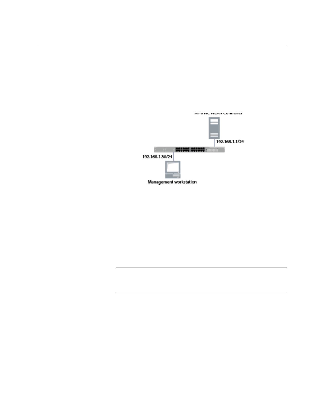
belongs to. See an example shown in Figure 1.
Chapter 1: Getting Started
Figure 1. AT-UWC WLAN Controller and Management Workstation
The AT-UWC WLAN Controller server has the following default IP address
and subnet mask assigned:
192.168.1.1/255.255.255.0
For the first time you access the AT-UWC WLAN Controller, your
management workstation must have an IP address in the following range:
192.168.1.2 to 192.168.1.254
To change the IP address of the management workstation, see
“Changing the IP Address” on page 21.
15
Page 16
AT-UWC WLAN Controller Web GUI User’s Guide
Starting a Management Session
The AT-UWC WLAN Controller is managed from the management
workstation through the Web GUI.
To start a management session of the AT-UWC WLAN Controller, do the
following:
1. Login to the management workstation.
If you do not have a management workstation, see “Preparing the
Management Workstation” on page 15.
2. Open Internet Explorer 7 or 8, and enter the IP address of the
AT-UWC WLAN Controller server.
The default IP address is
192.168.1.1.
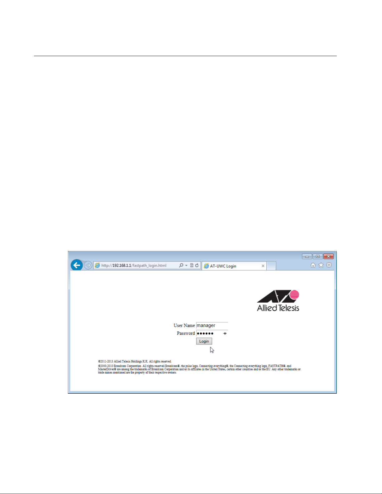
3. Enter the user name and password. See Figure 2.
The following are the default settings:
User name: manager
Password: friend
16
Figure 2. AT-UWC WLAN Controller Login Screen
4. Press Login.
Page 17

Registering the License Key
Registering the license key activates the AT-UWC WLAN Controller. For
the first time you login to the AT-UWC WLAN Controller, you must register
the license key.
License Key The license key is formed with the following two information:
A serial number
An authentication key
When you purchase the AT-UWC WLAN Controller software, you obtain a
license key that allows you to control 10 access point devices. To control
more access point devices, you can purchase an additional license key.
Chapter 1: Getting Started
30-day Free Trial
License
Registering the
License Key
Allied Telesis offers a 30-day free trial for new users. Two types of free trial
license keys are available:
AT-UWC-TrialST (NA): for users in North America
AT-UWC-TrialST (WW): for users worldwide except North America
You can download a free trial license from Allied Telesis Restricted
Software Downloads website. To obtain a free trial license, see
“Downloading the Free Trail License” on page 18 and follow the
instructions. On step 6, save AT-UWC-TrialST_(NA).pdf or
AT-UWC-TrialST_(WW).pdf.
To register the license key, see “License” on page 121.
17
Page 18
AT-UWC WLAN Controller Web GUI User’s Guide
Downloading the Free Trail License
Allied Telesis provides the license key from the Restricted Software
Downloads website.
To download the license key, do the following:
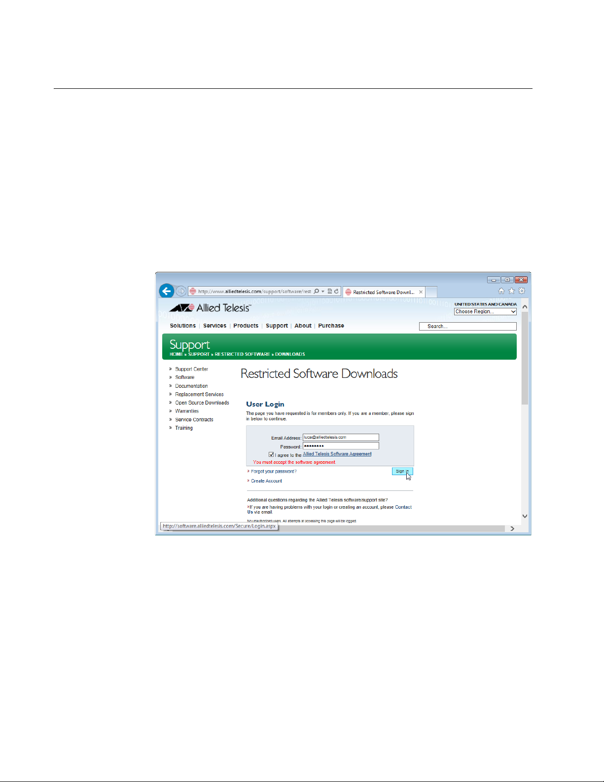
1. Open a web browser, such as Internet Explorer or FireFox, on your
system and enter the following:
http://www.alliedtelesis.com/support/software/restricted
The browser prompts you to enter a user name and password as
shown in Figure 3.
18
Figure 3. Restricted Software Downloads Login Page
2. Enter your email address and password.
If you do not have an account, create one. Click Create Account and
follow the instructions.
3. Read the Allied Telesis Software Agreement.
If you agree, check the checkbox and press Sign in.
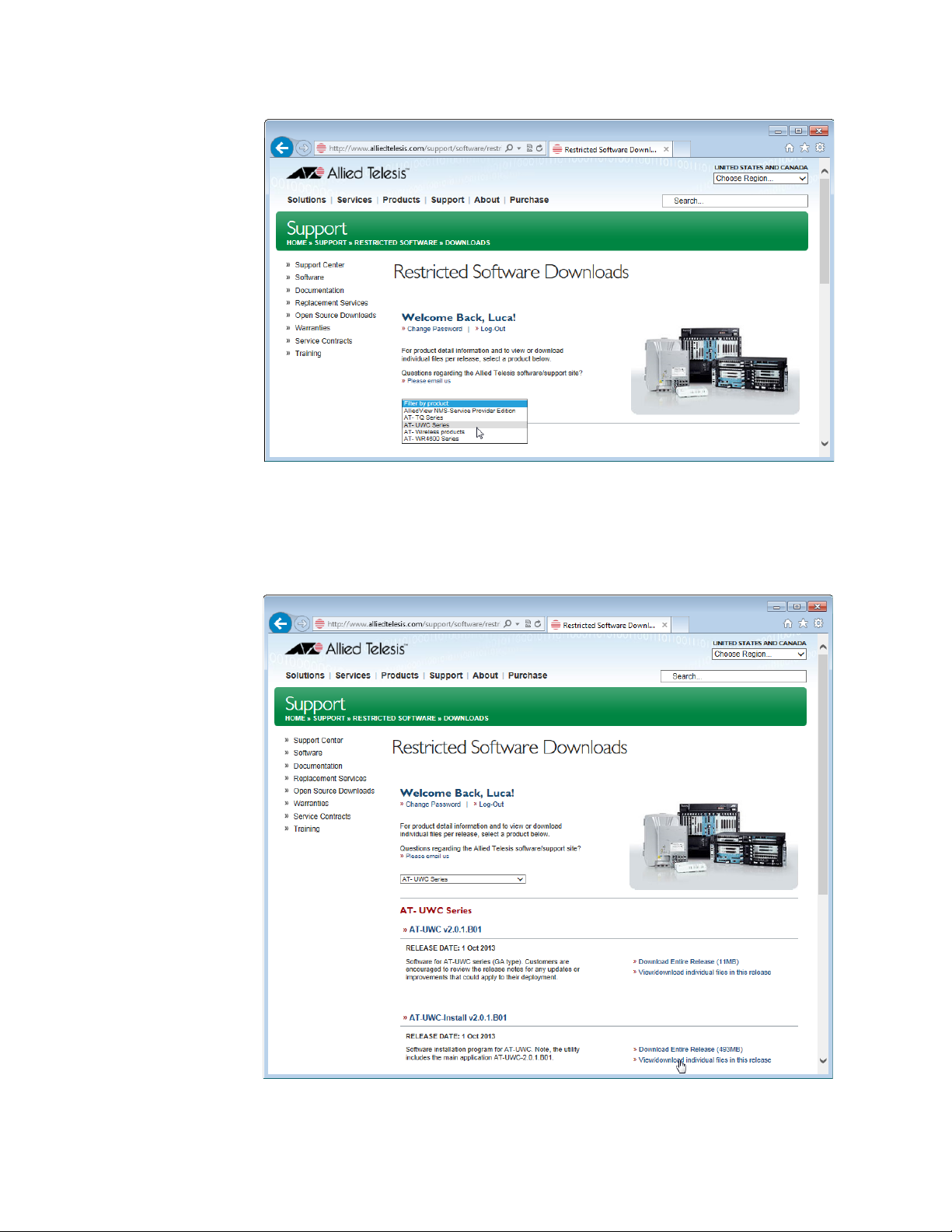
An example of the Restricted Software Downloads Welcome page is
displayed as shown in Figure 4 on page 19.
Page 19
Chapter 1: Getting Started
Figure 4. Restricted Software Downloads Welcome Page
4. Select AT-UWC Series from the select box.
The AT-UWC page is displayed as shown in Figure 5.
Figure 5. Restricted Software Downloads AT-UWC Page
19
Page 20
AT-UWC WLAN Controller Web GUI User’s Guide
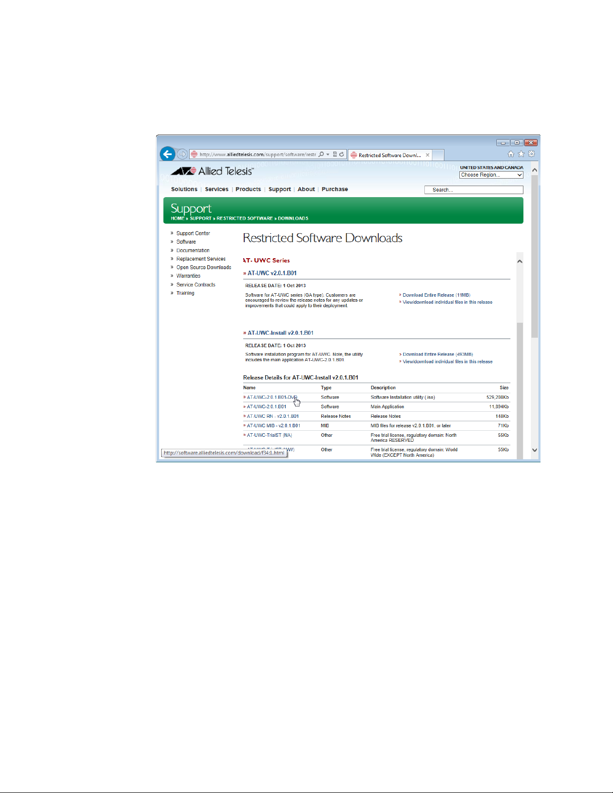
5. Click View/download individual files in this release under the
AT-UWC-Install v2.0.1.B01 section.
The available AT-UWC files are listed as shown in Figure 6.
20
Figure 6. Restricted Software Downloads AT-UWC Page
6. Select AT-UWC-TrialST (NA) or AT-UWC-TrialST (WW) rom the list
and save it onto your system.
Page 21
Changing the IP Address
When you access the AT-UWC WLAN Controller from the management
workstation, it must have an IP address form the same network as the
AT-UWC WLAN Controller server.
The procedures for changing the IP address is slightly different among
Windows Operating Systems. The following is the procedures using
Windows 7 as an example.
To change the IP address of a PC installed on Windows 7, do the
following:
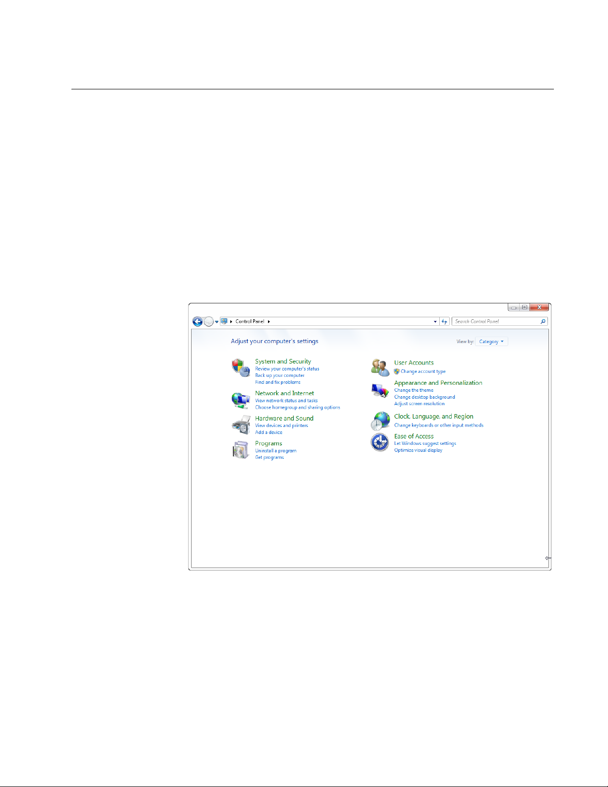
1. Click Control Panel from the Start button.
The control panel appears as shown in Figure 7.
Chapter 1: Getting Started
Figure 7. Control Panel
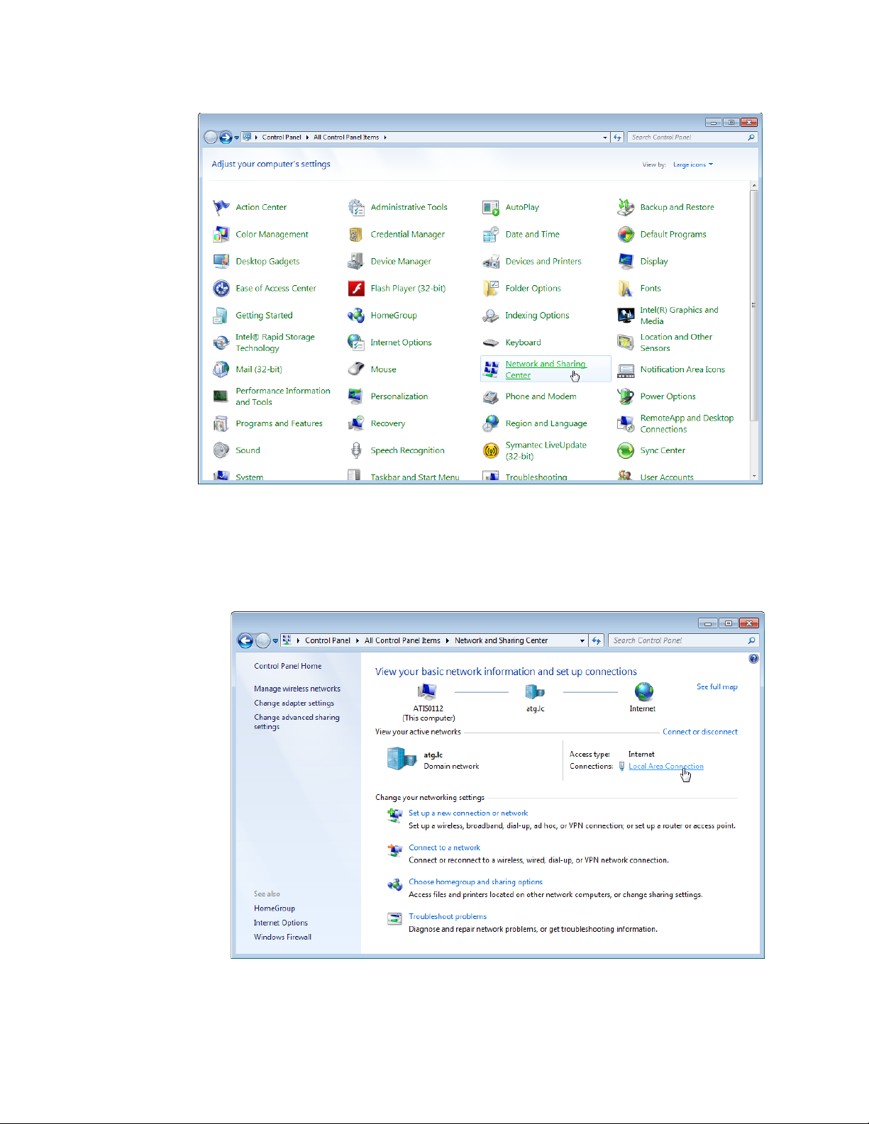
2. Click Category at the upper right corner of the window and select
Large icons.
Control Panel displays items with large icons as shown in Figure 8 on
page 22.
21
Page 22
AT-UWC WLAN Controller Web GUI User’s Guide
Figure 8. Control Panel with Large Icons
3. Click Network and Sharing Center.
The Basic Network Information window appears as shown in Figure 9.
22
Figure 9. Network Information Window
Page 23
Chapter 1: Getting Started
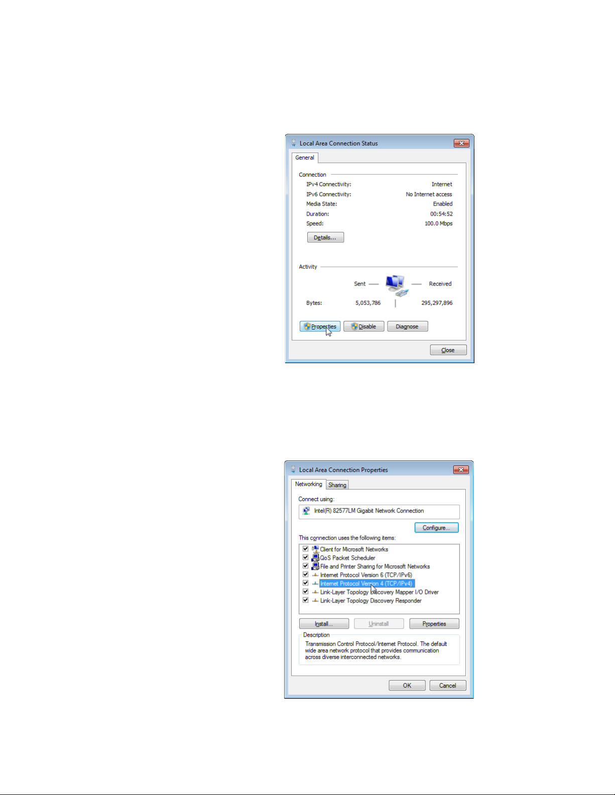
4. Click Local Area Connection.
The Local Area Connection Status window appears as shown in
Figure 10.
Figure 10. Local Area Connection Status Window
5. Click the Properties button at the bottom.
The Local Area Connection Properties window appears as shown in
Figure 11.
Figure 11. Local Area Connection Properties Window
23
Page 24
AT-UWC WLAN Controller Web GUI User’s Guide
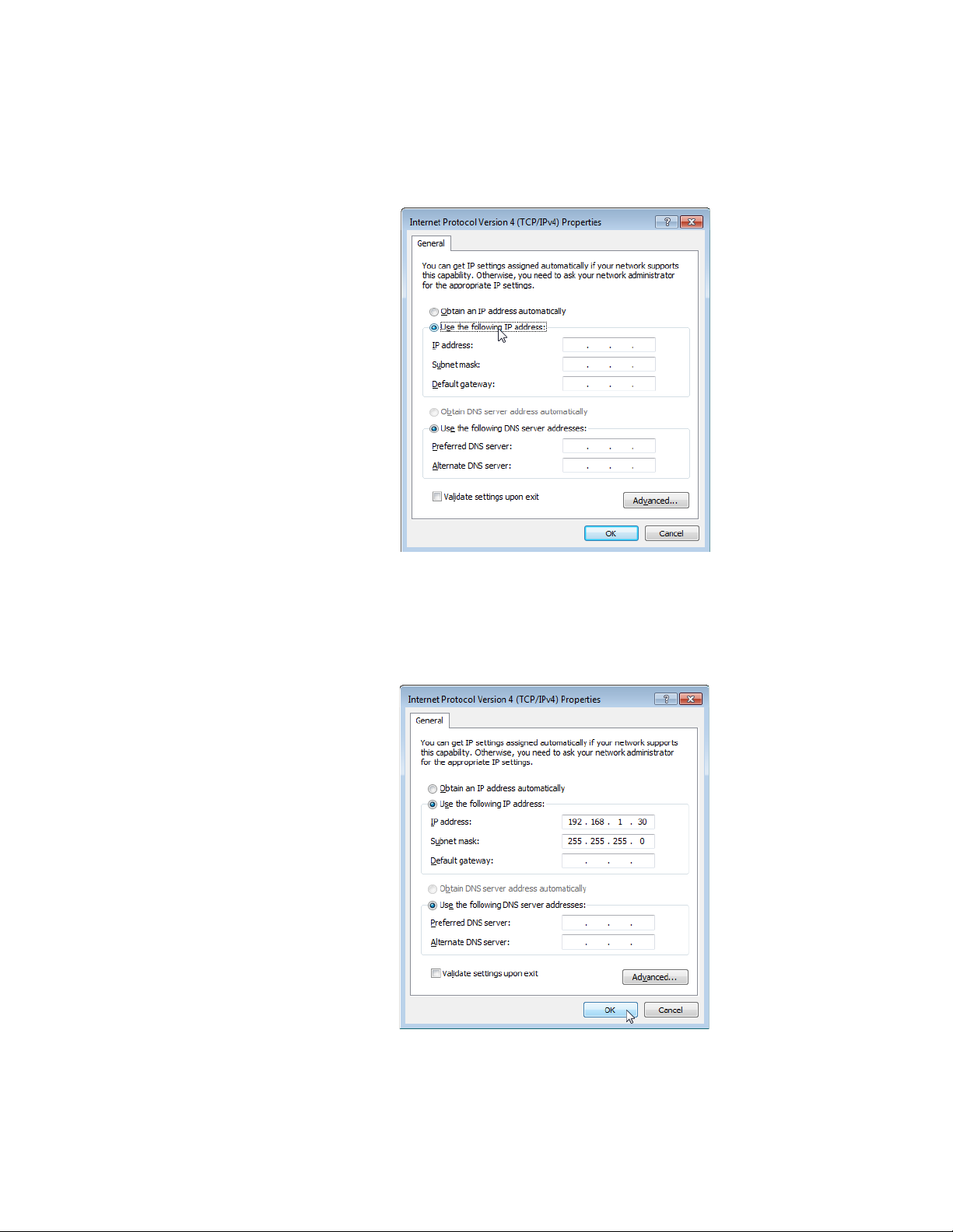
6. Double-click Internet Protocol Version 4 (TCP/IPv4).
The Internet Protocol Version 4 (IPv4) Properties window appears as
shown in Figure 12.
Figure 12. IPv4 Properties Window
7. Select the radio button labeled “Use the following IP address.”
8. Enter the IP address and Subnet mask. See Figure 13.
24
Figure 13. IPv4 Properties Window Example
9. Click OK.
Page 25
Enabling JavaScript
Note
To access the AT-UWC WLAN Controller, you must enable JavaScript for
your Windows Internet Explorer. You can enable JavaScript only when
accessing the AT-UWC WLAN Controller.
To enable JavaScript only for the AT-UWC WLAN Controller, do the
following:
1. Open the Windows Internet Explorer.
2. Click Tools from the menu bar.
3. Select Internet options from the drop-down menu.
Chapter 1: Getting Started
When JavaScript is already enabled, you do not have to change the
setting.
The Internet Options window pops up.
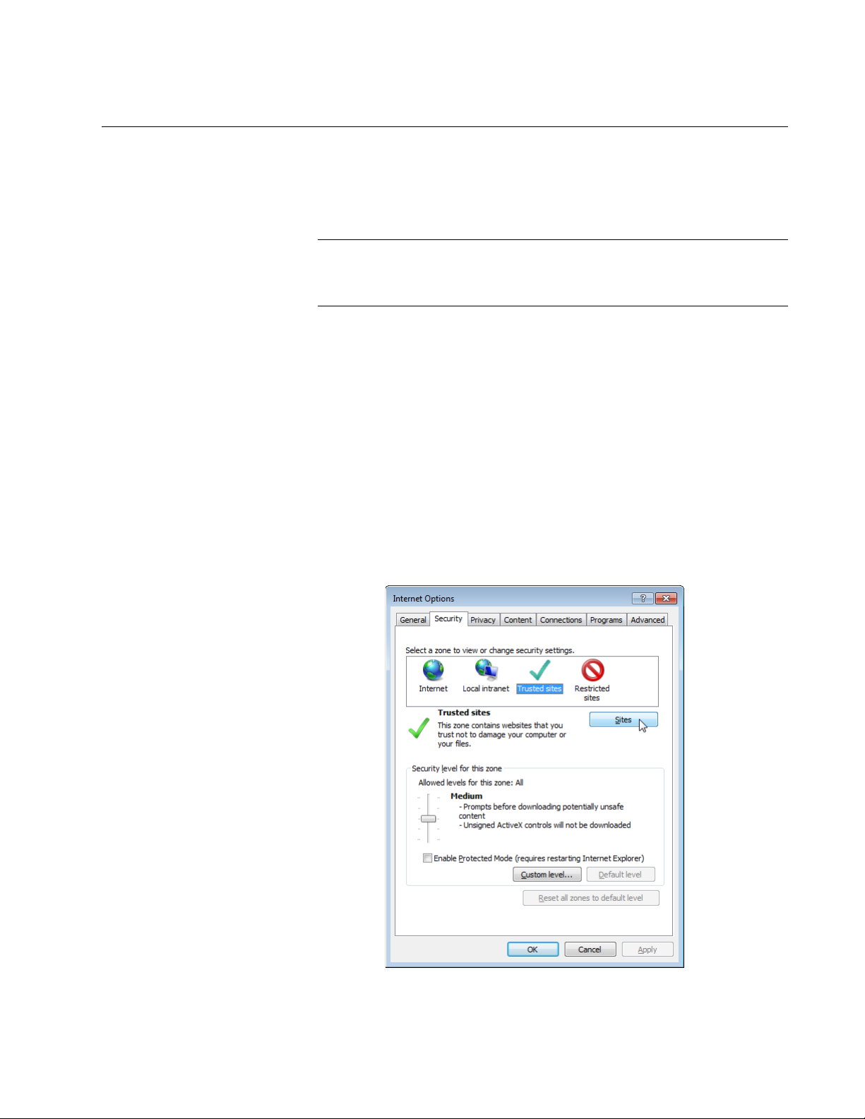
4. Click the Security tab on the Internet Options window.
The Internet Options window appears as shown in Figure 14.
Figure 14. Internet Options Window Security Tab
25
Page 26
AT-UWC WLAN Controller Web GUI User’s Guide
Note
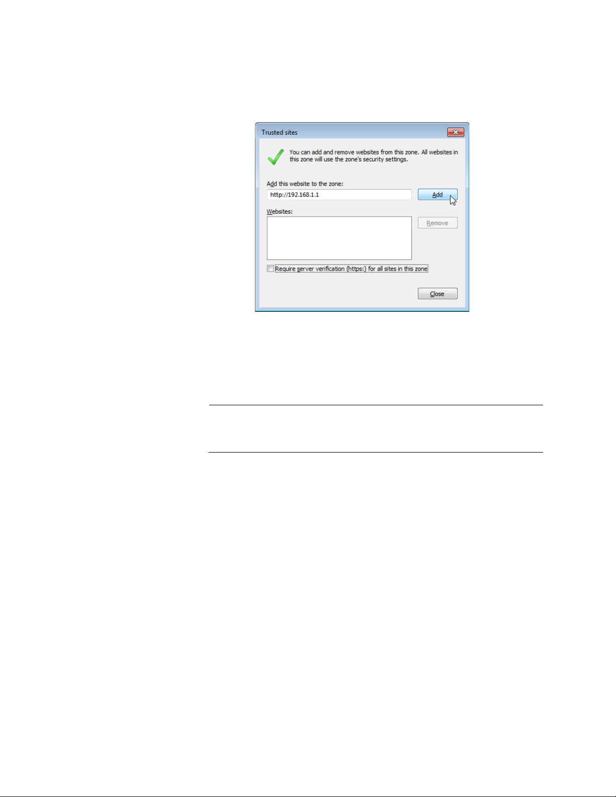
5. Select the Trusted sites icon in the box and press the Sites button.
The Trusted sites window appears as shown in Figure 15.
Figure 15. Trusted Sites Window
6. Enter the IP address of the AT-UWC WLAN Controller server and
check the checkbox of “Require server verification (https:) for all sites
in this zone.
By the default, the IP address of the AT-UWC WLAN Controller
server 192.168.1.1.
7. Click Add.
The Security Settings Internet Zone window appears as shown in
Figure 16 on page 27.
26
Page 27
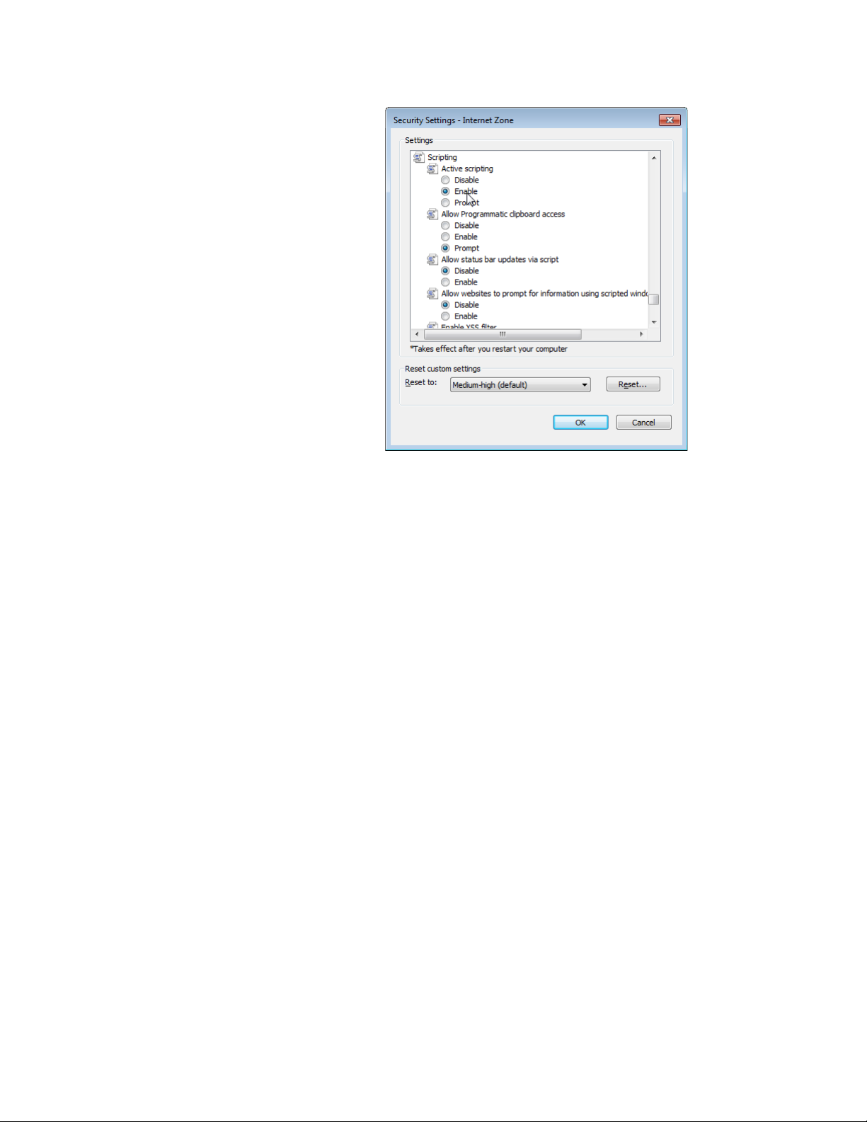
Chapter 1: Getting Started
Figure 16. Security Settings Window
8. Change the setting of Active scripting to Enable.
9. Click OK.
10. Restart the Internet Explorer.
JavaScript is enabled only when you access the AT-UWC WLAN
Controller.
27
Page 28

AT-UWC WLAN Controller Web GUI User’s Guide
Configuring the AT-UWC WLAN Controller
To configure the features of the AT-UWC WLAN Controller, look at the
Navigation panel on the left of the web page. Go to the page that you want
to configure. For more information on each page, see the following
chapters:
Chapter 2, “System” on page 37
Chapter 3, “Switching” on page 125
Chapter 4, “Security” on page 137
Chapter 5, “Wireless LAN” on page 189
28
Page 29
Saving the Changes
When you change settings of the AT-UWC WLAN Controller and click the
Submit button on each page, the changes are stored in the running
configuration. The settings in the running configuration are deleted when
the AT-UWC WLAN Controller reboots. You must save the changes to the
startup configuration if you want to keep the changes after the AT-UWC
WLAN Controller reboots.
To save the changes to the startup configuration, do the following:
1. Start a management session. See “Starting a Management Session”
Chapter 1: Getting Started
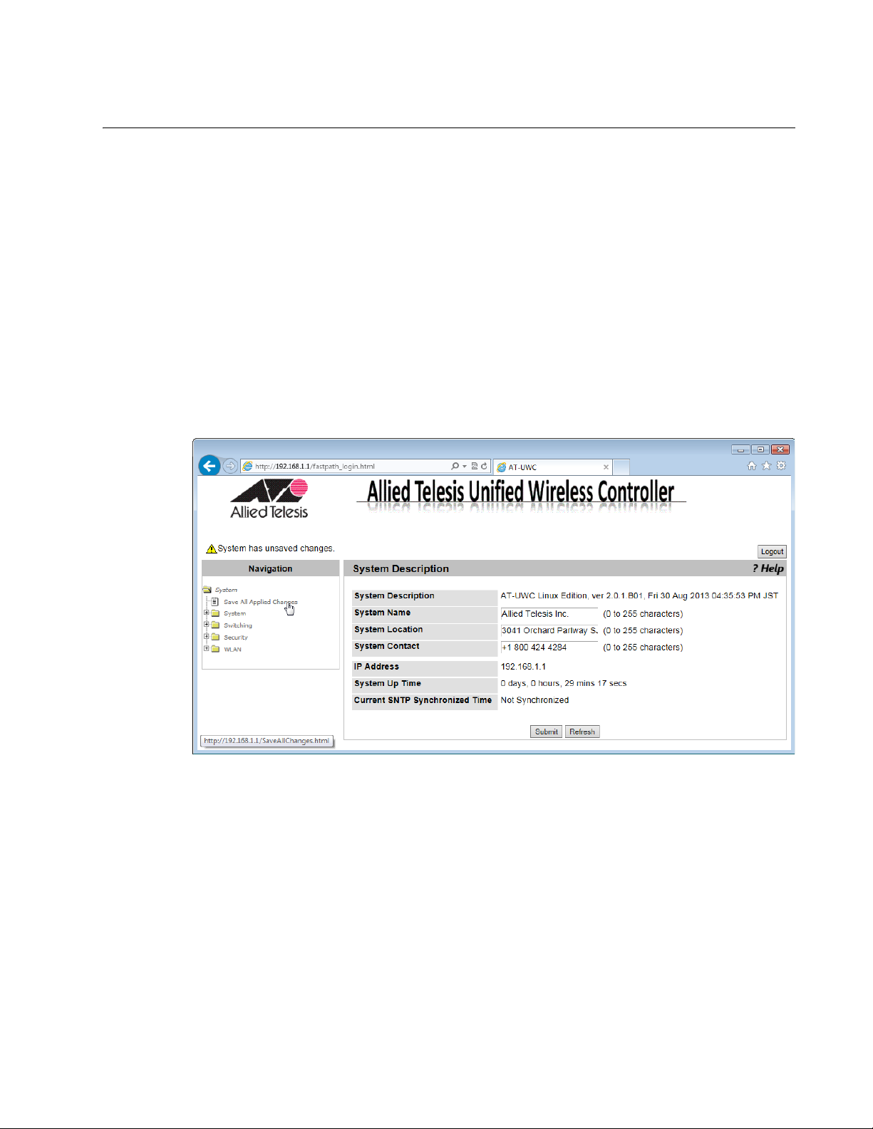
on page 16.
The Allied Telesis Unified Wireless Controller starts as shown in
Figure 17.
Figure 17. AT-UWC WLAN Controller Screen
2. From the Navigation panel on the left, go to System > Save All
Applied Changes.
The Save All Applied Changes screen is displayed as shown in Figure
18 on page 30.
29
Page 30
AT-UWC WLAN Controller Web GUI User’s Guide
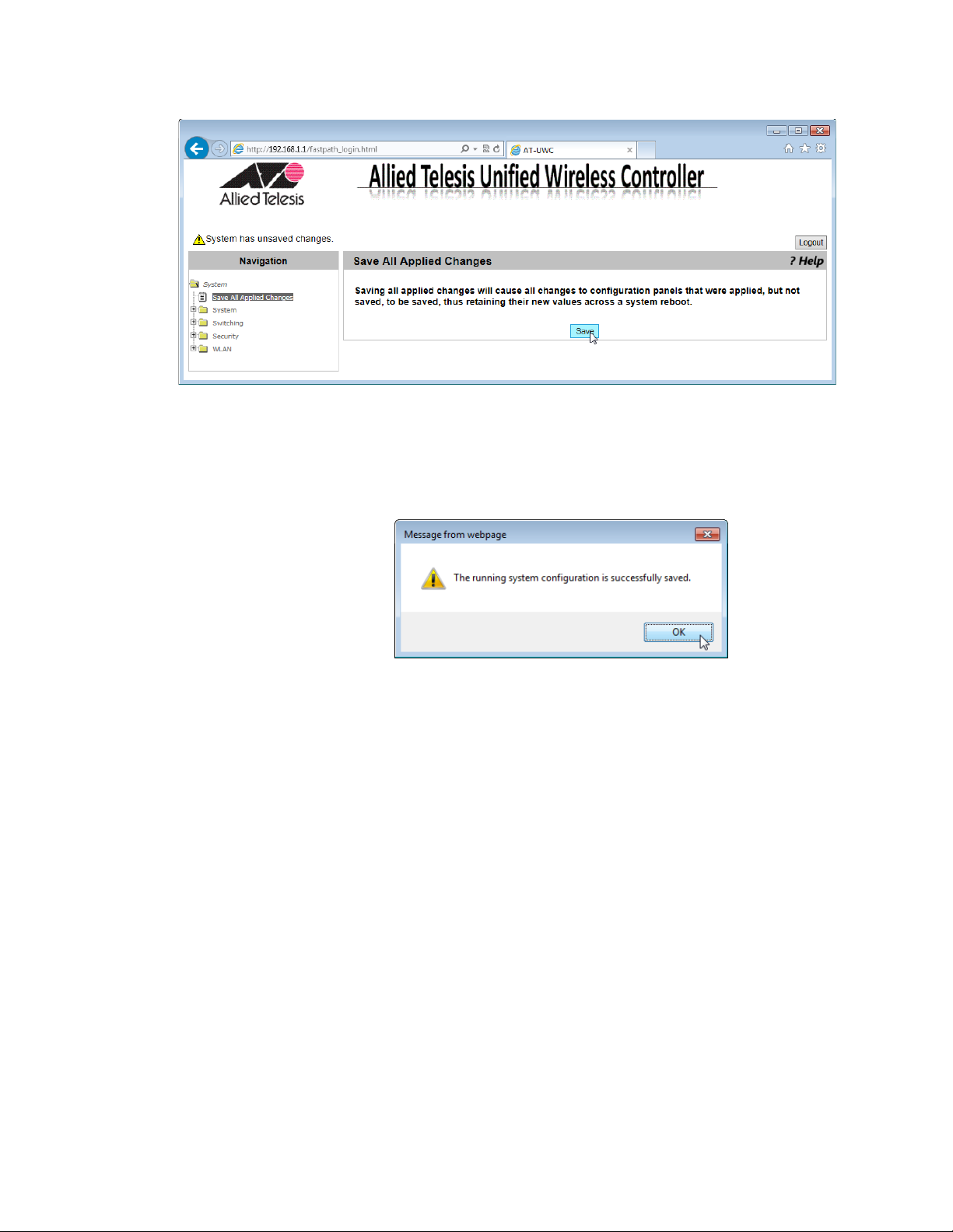
3. Click Save.
The Confirmation window appears as shown in Figure 19.
Figure 18. AT-UWC WLAN Controller Save Changes Screen
Figure 19. Confirmation Window
The changes are saved to the startup configuration.
30
Page 31

Using Online Help
Chapter 1: Getting Started
When you have a question about the AT-UWC WLAN Controller, the
Online Help can be a good place to look for your answer.
To access the Online Help, do the following:
1. Start a management session. See “Starting a Management Session”
on page 16.
The Allied Telesis Unified Wireless Controller screen is displayed as
shown in Figure 20.
Figure 20. AT-UWC WLAN Controller Screen
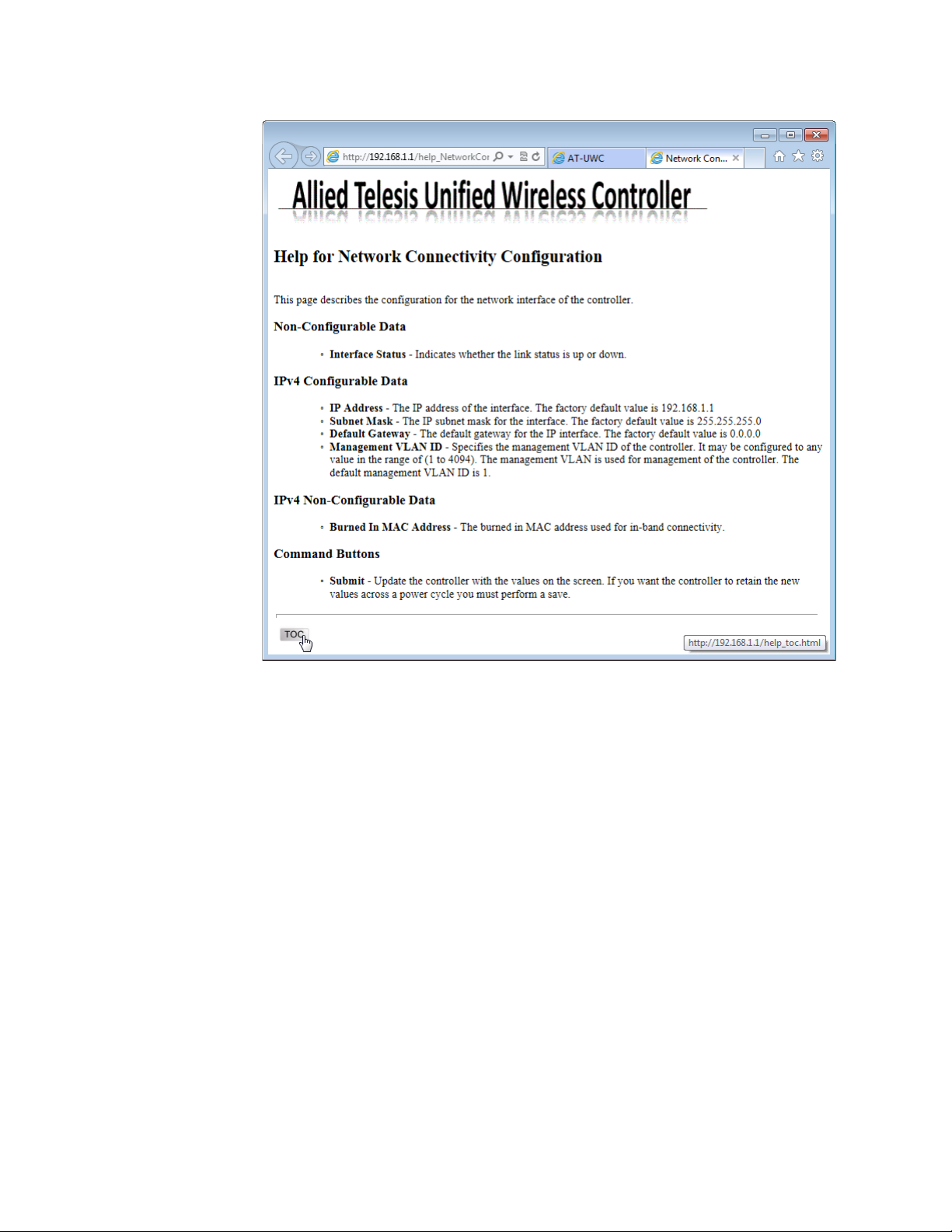
2. Click ?Help.
The Online Help is displayed shown in Figure 21 on page 32.
31
Page 32
AT-UWC WLAN Controller Web GUI User’s Guide
Figure 21. AT-UWC WLAN Controller Online Help
3. Click the TOC button at the lower left corner of the screen.
The Online Help Table of Contents is displayed shown in Figure 22 on
page 33.
32
Page 33

Chapter 1: Getting Started
Figure 22. AT-UWC WLAN Controller Online Help TOC
4. Click the Configuration on the Table of Contents for example.
The Online Help Configuration portion is displayed shown in Figure 23
on page 34.
33
Page 34

AT-UWC WLAN Controller Web GUI User’s Guide
Figure 23. AT-UWC WLAN Controller Online Help Example
34
Page 35

Ending a Management Session
You can end a management session at any time during a management
session.
To end a management session, do the following:
1. Save the changes to the startup configuration.
See “Saving the Changes” on page 29. If you do not want to save your
changes, skip this step.
2. Click the Logout button on the right side of the screen.
See Figure 24 as an example.
Chapter 1: Getting Started
Figure 24. AT-UWC WLAN Controller Screen
The management session ends.
35
Page 36

AT-UWC WLAN Controller Web GUI User’s Guide
36
Page 37

Chapter 2
System
This chapter includes the following topics. Each topic corresponds to the
same title in the System folder in the Navigation Panel on the Web GUI.
“Save All Applied Changes” on page 39
“ARP Cache” on page 40
“System Resources” on page 41
Configuration
“System Description” on page 43
“Network Connectivity Configuration” on page 45
“HTTP” on page 47
“Telnet Session” on page 49
“User Accounts Configuration” on page 50
“Login Sessions” on page 52
Forwarding Database
“Forwarding Database Configuration” on page 54
“Forwarding Database Search” on page 55
Logs
“Buffered Log Configuration” on page 57
“Buffered Log” on page 59
“Command Logger Configuration” on page 60
“Console Log Configuration” on page 61
“Event Log” on page 62
“Hosts Log Configuration” on page 63
“Persistent Log Configuration” on page 65
“Persistent Log” on page 68
“Syslog Configuration” on page 69
“Diagnosis Log Configuration” on page 71
SNMP
“SNMP Community Configuration” on page 73
37
Page 38

AT-UWC WLAN Controller Web GUI User’s Guide
“Trap Receiver Configuration” on page 75
“Supported MIBs” on page 77
Statistics
“Controller Detailed Statistics” on page 78
“Controller Statistics Summary” on page 81
System Utility
“System Reset” on page 82
“Reset Configuration To Default” on page 83
“Erase Startup Configuration File” on page 85
“Reset Passwords to Defaults” on page 87
“Download File to Controller” on page 88
“Upload File from Controller” on page 90
“Buffered Log Configuration” on page 57
“Software Upgrade” on page 94“Ping” on page 96
“Ping” on page 96
“TraceRoute” on page 98
Trap Manager
“Trap Flags” on page 100
“Trap Logs” on page 102
DNS
“DNS Global Configuration” on page 104
“DNS Server Configuration” on page 107
“HostName IP Mapping Summary” on page 109
SNTP
“SNTP Global Configuration” on page 112
“SNTP Global Status” on page 114
“SNTP Server Configuration” on page 117
“SNTP Server Status” on page 119
License
38
“License” on page 121
Page 39

Save All Applied Changes
Note
From the Save All Applied Changes page, you can save all the changes
you have made to the startup configuration file. When you save your
changes to the startup configuration file, the changes are effective after
the system reboots.
When you click Submit on each page, you save your changes on
the page to the running configuration file. The changes are effective
immediately; however, when the system is reset, the changes are
lost.
To save all the changes to the startup configuration file, do the following:
1. From the Navigation pane, go to Save All Applied Changes.
The Save All Applied Changes page is displayed as shown in
Figure 25.
Chapter 2: System
Figure 25. Save All Applied Changes Page
2. Click Save.
39
Page 40

AT-UWC WLAN Controller Web GUI User’s Guide
ARP Cache
From the ARP Cache page, you can view and clear the Address
Resolution Protocol (ARP) cache. ARP stores map entries in the ARP
cache to map IP addresses to MAC addresses. Clear the ARP cache
when it may be corrupted or damaged.
To view and clear the ARP cache, do the following:
1. From the Navigation pane, go to System > ARP Cache.
The ARP Cache page is displayed as shown in Figure 26.
Figure 26. System ARP Cache Page
2. Observe the ARP cache.
3. Click the following buttons as needed:
Refresh — Refreshes the display on this page.
Clear — Delete all entries in the ARP Cache.
40
Page 41

System Resources
Chapter 2: System
From the System Resources page, you can view the information about the
system resources.
To view the system resources, do the following:
1. From the Navigation pane, go to System > System Resources.
The System Resources page is displayed as shown in Figure 27.
Figure 27. System Resources Page
2. Observe the fields described in Table 1.
Table 1. System Resources
Field Description
Memory Usage
Free Memory
(kbytes)
Alloc Memory
(kbytes)
CPU Utilization Report
Task Id Displays the ID of the task that is currently running.
Task Name Displays the name of the task that is currently
Displays the available memory on the system in
kilo bytes.
Displays the allocated memory on the system in
kilo bytes.
running.
41
Page 42

AT-UWC WLAN Controller Web GUI User’s Guide
5 Seconds Displays the CPU usage by the task in the last 5
60 Seconds Displays the CPU usage by the task in the last 60
300 Seconds Displays the CPU usage by the task in the last 300
Table 1. System Resources (Continued)
Field Description
seconds.
seconds.
seconds.
Tot al C PU
Displays the total CPU usage by all the tasks.
Utilization
3. If you want to refresh the display, click Refresh.
42
Page 43

System Description
Chapter 2: System
From the System Description page, you can view and modify system
information.
To view and modify the system information, do the following:
1. From the Navigation pane, click System or go to System >
Configuration > System Description.
The System Description page is displayed as shown in Figure 28.
Figure 28. System Description Page
2. Observe and modify the values in the fields described in Table 2.
Table 2. System Description
Field Description
System
Description
System Name Displays the system name of the WLAN Controller.
System Location Displays the system location of the WLAN
System Contact Displays the contact information. By default, no
Displays the product name, version, and time
stamp of the currently installed WLAN Controller
software.
By default, no system name is assigned.
Controller. By default, no system name is assigned.
system contact is assigned.
43
Page 44

AT-UWC WLAN Controller Web GUI User’s Guide
Note
IP Address Displays the IP address of the WLAN Controller. To
System Up Time Displays the length of time since the lWLAN
Table 2. System Description (Continued)
Field Description
change the IP address, see “Network Connectivity
Configuration” on page 45.
Controller last rebooted.
Current SNTP
Synchronized
Time
Displays the system time from the currently
synchronized SNTP. For information about SNTP,
see ““SNTP Global Status” on page 114”
3. Click the following buttons as needed:
Refresh — Refreshes the display on this page.
Submit — Makes the changes effective and saves them to the
running configuration file.
To save your changes to the startup configuration file, see “Save All
Applied Changes” on page 39.
44
Page 45

Network Connectivity Configuration
From the Network Connectivity Configuration page, you can view and
modify the network interface properties.
To view and modify the network interface properties, do the following:
1. From the Navigation pane, go to System > Configuration > Network
Connectivity Configuration.
The Network Connectivity Configuration page is displayed as shown in
Figure 29.
Chapter 2: System
Figure 29. Network Connectivity Configuration Page
2. Observe or modify the values in the fields described in Table 3.
Table 3. Network Connectivity Configuration
Field Description
Interface Status Displays the status of the interface on the WLAN
Controller.
IP Address Displays the IP address of the WLAN Controller.
The default value is 192.168.1.1.
Subnet Mask Displays the subnet mask of the WLAN Controller.
The default value is 255.255.255.0.
Default Gateway Displays the default gateway to the WLAN
Controller. By default, no value is assigned.
45
Page 46

AT-UWC WLAN Controller Web GUI User’s Guide
Note
Table 3. Network Connectivity Configuration (Continued)
Field Description
Burned In MAC
Displays the MAC address of the WLAN Controller.
Address
Management
VLAN ID
Displays the management VLAN ID. The default
value is VLAN 1
3. Click the following buttons as needed:
Refresh — Refreshes the display on this page.
Submit — Makes the changes effective and saves them to the
running configuration file.
To save your changes to the startup configuration file, see “Save All
Applied Changes” on page 39.
46
Page 47

HTTP
Chapter 2: System
On the HTTP Configuration page, you can view and modify the property
settings for HTTP connections.
To view and modify the HTTP settings, do the following:
1. From the Navigation pane, go to System > Configuration > HTTP.
The HTTP Configuration page is displayed as shown in Figure 30.
Figure 30. HTTP Configuration Page
2. Observe or modify the values in the fields described in Table 4.
Table 4. HTTP Configuration
Field Description
HTTP Admin
Mode
HTTP Session
Soft Timeout
(Minutes)
HTTP Session
Hard Timeout
(Hours)
Displays Enable or Disable. By default, HTTP is
enabled. When you enable HTTPS, HTTP is
disabled. See “Secure HTTP” on page 187.
Displays the period of time in minutes. When this
specified time has passed since the last userinteraction to the system, the system ends the
session. The default setting is 5 minutes.
Displays the period of time in hours. When this
specified time has passed since the time you
logged in, the system ends the session. The default
setting is 24 hours.
47
Page 48

AT-UWC WLAN Controller Web GUI User’s Guide
Note
Table 4. HTTP Configuration (Continued)
Field Description
Maximum
Number of HTTP
Session
Displays the maximum number of HTTP sessions
that you allows to the WLAN Controller. The default
setting is 16 sessions.
3. Click the following buttons as needed:
Refresh — Refreshes the display on this page.
Submit — Makes the changes effective and saves them to the
running configuration file.
To save your changes to the startup configuration file, see “Save All
Applied Changes” on page 39.
48
Page 49

Telnet Session
Note
Chapter 2: System
The current AT-UWC WLAN Controller does not support the Telnet
Session.
49
Page 50

AT-UWC WLAN Controller Web GUI User’s Guide
Note
Note
User Accounts Configuration
From the User Accounts Configuration page, you can modify the
password for the manager account.
The create option in the User field and guest account are not
supported for the current version.
Allied Telesis recommends not changing the access level of the
manager account. Change only the password of the manager
account.
To modify the password of the manager account, do the following:
1. From the Navigation pane, go to System > Configuration > User
Accounts Configuration.
The User Accounts Configuration page is displayed as shown in
Figure 31.
Figure 31. User Accounts Configuration Page
2. Observe the fields described in Table 5 on page 51.
50
Page 51

Chapter 2: System
Note
Table 5. User Accounts Configuration
Field Description
User Select the manager option. The following items are
visible from the select list:
manager: Modifies the manager account.
quest: Not supported.
create: Not supported.
User Name Displays the name of the user account. You cannot
modify the name.
Password Enter a password. The password is not displayed.
Confirm
Re-enter the password.
Password
Access Level Allied Telesis recommends not changing the
access level.
3. Click Submit.
The changes are saved to the running configuration file.
To save your changes to the startup configuration file, see “Save All
Applied Changes” on page 39.
51
Page 52

AT-UWC WLAN Controller Web GUI User’s Guide
Login Sessions
From the Login Sessions page, you can view information about your
current login session.
To view information about your login session, do the following:
1. From the Navigation pane, go to System > Configuration > Login
Sessions.
The Login Sessions page is displayed as shown in Figure 32.
52
Figure 32. Login Sessions Page
2. Observe the fields described in Table 6.
Table 6. Login Session
Field Description
ID Displays the ID number of your login session.
User Name Displays the name of login user.
Connection From Displays the IP address of your management
workstation.
Idle Time Displays the length of time since the WLAN
Controller received traffic last time.
Session Time Displays the length of time since you logged into
the WLAN Controller.
Page 53

Chapter 2: System
Table 6. Login Session (Continued)
Field Description
Session Type Displays the connection type, either HTTP or
HTTPS.
3. If you want to refresh the display, click Refresh.
53
Page 54

AT-UWC WLAN Controller Web GUI User’s Guide
Note
Forwarding Database Configuration
From the Forwarding Database Configuration page, you can change the
aging interval for the forwarding database. A forwarding database is also
called a MAC address table that Layer 2 devices keep to associate MAC
addresses to the ports.
To change the aging interval for the forwarding database, do the following:
1. From the Navigation pane, go to System > Forwarding Database >
Configuration.
The Forwarding Database Configuration page is displayed as shown
in Figure 33.
54
Figure 33. Forwarding Database Configuration Page
2. Specify the aging interval in seconds.
The aging interval is the number of seconds the entry of a MAC
address is kept in the forwarding database. The default is 300
seconds.
3. Click Submit.
The change is saved to the running configuration file.
To save your changes to the startup configuration file, see “Save All
Applied Changes” on page 39.
Page 55
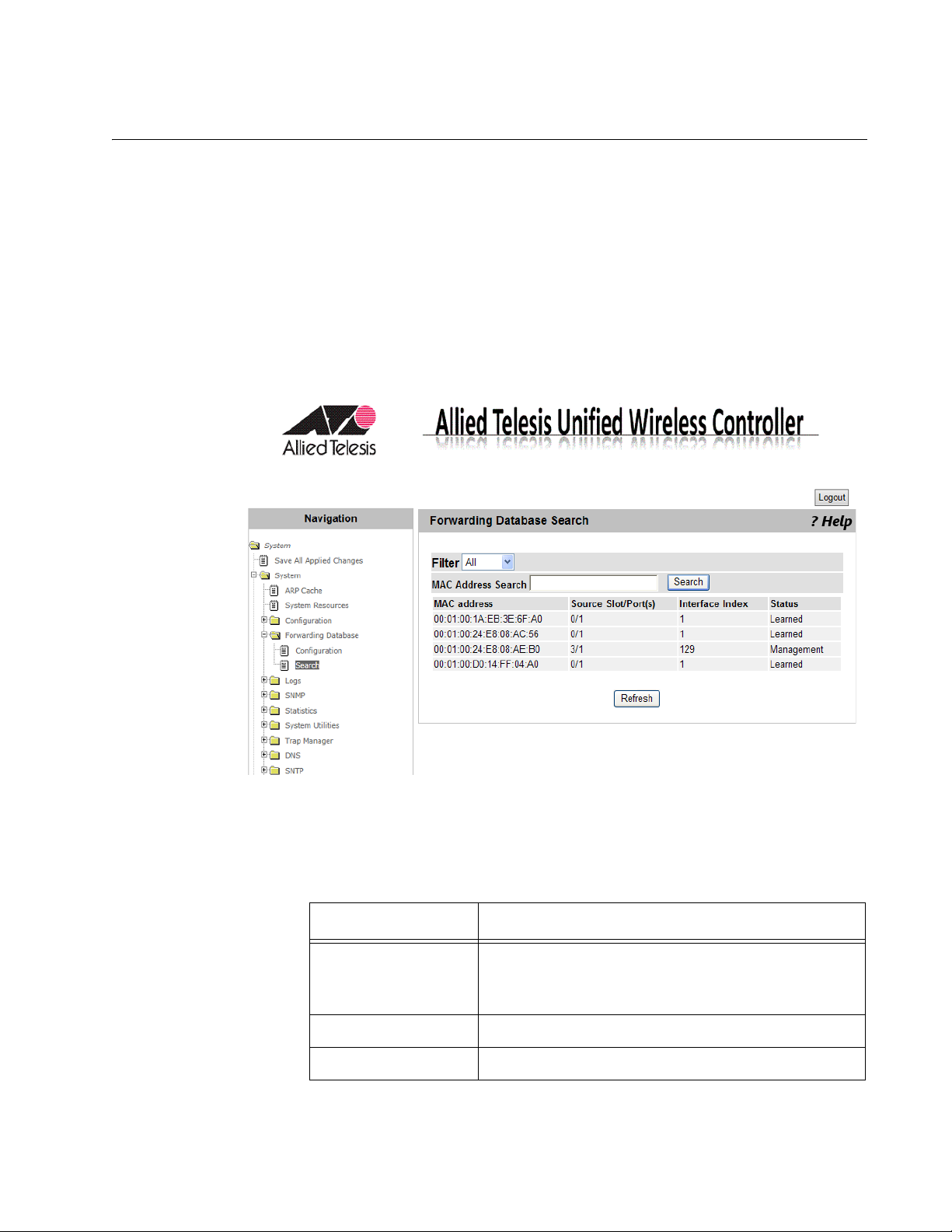
Forwarding Database Search
From the Forwarding Database Search page, you can view MAC address
entries and search a specific MAC address from the database.
Chapter 2: System
Viewing the
Forwarding
Database
To view the forwarding database, do the following:
1. From the Navigation pane, go to System > System > Forwarding
Database > Search.
The Forwarding Database Search page is displayed as shown in
Figure 34.
Figure 34. Forwarding Database Search Page
2. Observe the fields as shown in Table 7.
Table 7. Forwarding Database
Field Description
MAC address The first two groups of hexadecimal digits
indicate the VLAN ID. The rest of the
hexadecimal digits indicates the MAC address.
Source Slot/Port(0) Indicates the port number.
Interface Index Indicates the interface index.
55
Page 56

AT-UWC WLAN Controller Web GUI User’s Guide
Status Indicates the status of the MAC address entry.
3. If you want to refresh the display, click Refresh.
Table 7. Forwarding Database (Continued)
Field Description
The options are:
Learned: The MAC address was learned
from received frames.
Management: Indicates that MAC
address is of the WLAN Controller.
Searching a MAC
Address
To search a MAC address from the forwarding database, do the following:
1. From the Navigation pane, go to System > System > Forwarding
Database > Search.
The Forwarding Database Search page is displayed as shown in
Figure 34 on page 55.
2. Select one of the following filtering options from the select list:
All: Specifies the search in the entire forwarding database.
Learned: Specifies the search in the MAC addresses with the
Learned status.
3. Enter the combination of a VLAN ID and a MAC address in
hexadecimal in the following format:
xx:xx:xx:xx:xx:xx:xx:xx
4. Click Search.
The result is displayed.
56
Page 57

Buffered Log Configuration
Note
From the Buffered Log Configuration page, you can enable or disable the
Buffered Log function. The system stores up to 200 log messages in the
buffer and deletes them when the system shuts down.
To download buffered log messages, see “Upload File from
Controller” on page 90.
To enable or disable the buffered log function, do the following:
1. From the Navigation pane, go to System > Logs > Buffered Log
Configuration.
The Buffered Log Configuration page is displayed as shown in
Figure 35.
Chapter 2: System
Figure 35. Buffered Log Configuration Page
2. Select the options in the fields described in Table 8 on page 58.
57
Page 58

AT-UWC WLAN Controller Web GUI User’s Guide
Note
Admin Status Starts or stops logging messages. The options are:
Behavior Specifies the logging behavior. The options are:
3. Click one of the following buttons:
Table 8. Buffered Log Configuration
Field Description
Enable: Starts logging messages into the
buffer.
Disable: Stops logging messages into the
buffer.
Wrap: Replaces the last saved messages
with new messages when the buffer is full.
Stop on Full: Stops logging when the buffer
is full.
Refresh — Refreshes the display on this page.
Submit — Saves the changes to the running configuration file.
To save your changes to the startup configuration file, see “Save All
Applied Changes” on page 39.
58
Page 59

Buffered Log
Chapter 2: System
From the Buffered Log page, you can view messages stored in the buffer
on the WLAN Controller.
To view messages in the buffered log, do the following:
1. From the Navigation pane, go to System > Logs > Buffered Log.
The Buffered Log page is displayed as shown in Figure 36.
Figure 36. Buffered Log Page
2. Observe the messages.
3. If you want to refresh the display, click Refresh.
59
Page 60

AT-UWC WLAN Controller Web GUI User’s Guide
Note
Command Logger Configuration
The current AT-UWC WLAN Controller does not support the
Command Logger.
60
Page 61

Console Log Configuration
Note
The current AT-UWC WLAN Controller does not support the
Console Log.
Chapter 2: System
61
Page 62

AT-UWC WLAN Controller Web GUI User’s Guide
Note
Event Log
From the Event Log page, you can view event log messages.
To download event log messages, see “Upload File from Controller”
on page 90.
To view event log messages, do the following:
1. From the Navigation pane, go to System > Logs > Event Log.
The Event Log page is displayed as shown in Figure 37.
Figure 37. Event Log Page
2. Observe the messages.
3. If you want to refresh the display, click Refresh.
62
Page 63

Hosts Log Configuration
Note
From the Hosts Log Configuration page, you can add Syslog servers.
To start or stop sending log messages to Syslog servers, see
“Syslog Configuration” on page 69.
To add a Syslog server, do the following:
1. From the Navigation pane, go to System >> Logs > Hosts Log
Configuration.
The Hosts Log Configuration page is displayed as shown in Figure 38.
Chapter 2: System
Figure 38. Hosts Log Configuration Page
2. Select the options in the fields described in Table 9.
Table 9. Hosts Log Configuration
Field Description
Host Displays the action. Add is the only option.
IP Address
Hostname
Specifies an IPv4 address or host name of the
Syslog server where log messages are sent.
63
Page 64

AT-UWC WLAN Controller Web GUI User’s Guide
Note
IP Address Type Specifies the IP address type. The options are:
3. Click one of the following buttons:
Refresh — Refreshes the display on this page.
Submit — Saves the changes to the running configuration file.
To save your changes to the startup configuration file, see “Save All
Applied Changes” on page 39.
Table 9. Hosts Log Configuration (Continued)
Field Description
IPv4: Specifies a Syslog server with its IPv4
address.
DNS: Specifies a Syslog server with its host
name.
64
Page 65

Persistent Log Configuration
Note
From the Persistent Log Configuration page, you can enable or disable the
Persistent Log feature.
When the Persistent Log feature is enabled, the system stores log
messages in a file on the hard disk. The system creates a new log file
when rebooting. When the system has three log files, it replaces the oldest
log file with a new.
To download persistent log messages, see “Upload File from
Controller” on page 90.
To enable or disable the Persistent Log feature, do the following:
1. From the Navigation pane, go to System > Logs > Persistent Log
Configuration.
Chapter 2: System
The Persistent Log Configuration page is displayed as shown in
Figure 39.
Figure 39. Persistent Log Configuration Page
2. Select the options in the fields described in Table 10 on page 66.
65
Page 66

AT-UWC WLAN Controller Web GUI User’s Guide
Note
Admin Status Starts or stops logging messages in the hard disc.
Severity Filter Specifies the Severity filter. The options are:
Table 10. Persistent Log Configuration
Field Description
The options are:
Enable: Starts logging messages on the
hard disc.
Disable: Stops logging messages on the
hard disc.
Emergency: Stores messages with the
emergency level. This is the highest level of
severity.
Alert: Stores messages with the alert and
the higher severity level.
Critical: Stores messages with the critical
and the higher severity levels.
Error: Stores messages with the error and
the higher severity levels.
Warning: Stores messages with the
warning and the higher severity levels.
Notice: Stores messages with the notice
and the higher severity levels.
Info: Stores messages with the info and the
higher severity levels.
Debug: Stores messages with the debug
and all the other levels.
For more information about the severity filter, see
“Log Message Levels” on page 67.
3. Click Submit.
The change is saved to the running configuration file.
To save your changes to the startup configuration file, see “Save All
Applied Changes” on page 39.
66
Page 67

Chapter 2: System
Severity Levels Table 11 describes the severity levels in decreasing order of severity.
Table 11. Log Message Levels
Severity Level Description
0 Emergency The system is disabled. This is the highest
level of severity.
1 Alert The system requires an immediate action.
2 Critical The system is in the critical condition.
3 Error An error occurred.
4 Warning An event that leads to an error occurred.
5 Notice A noticeable event occurred.
6 Info Incudes information.
7 Debug Includes information to help debugging.
67
Page 68

AT-UWC WLAN Controller Web GUI User’s Guide
Note
Persistent Log
From the Persistent Log page, you can view persistent log messages
stored in the hard disk on the WLAN Controller.
To configure the Persistent Log feature, see “Persistent Log
Configuration” on page 65.
To view messages in the Persistent log, do the following:
1. From the Navigation pane, go to System > Logs > Persistent Log.
The Persistent Log page is displayed as shown in Figure 40.
Figure 40. Persistent Log Page
2. Observe the messages.
3. If you want to refresh the display, click Refresh.
68
Page 69

Syslog Configuration
Note
From the Syslog Configuration page, you can start or stop sending log
messages to Syslog servers.
To start or stop sending log messages to Syslog servers, do the following:
1. From the Navigation pane, go to System > System > Logs > Syslog
Chapter 2: System
To set Syslog servers, see “Hosts Log Configuration” on page 63.
Configuration.
The Syslog Configuration page is displayed as shown in Figure 41.
Figure 41. Syslog Configuration Page
2. Select the options in the fields described in Table 12.
Table 12. Syslog Configuration
Field Description
Admin Status Starts or stops sending messages to syslog
servers. The options are:
Enable: Starts sending log messages to
Syslog servers.
Disable: Stops sending log messages to
Syslog servers.
69
Page 70

AT-UWC WLAN Controller Web GUI User’s Guide
Note
Local UDP Port Displays the UDP port number used to sent log
Messages Received Displays the number of log messages that the
Messages Dropped Displays the number of log messages that have
Messages Relayed Displays the total number of log messages that
3. Click Submit.
Table 12. Syslog Configuration (Continued)
Field Description
messages to syslog servers. The default port
number is 514.
process received, including discarded messages.
an error or were discarded due to lack of space.
were sent to syslog servers. If a message is sent
to three syslog servers, the message is counted
three.
The change is saved to the running configuration file.
To save your changes to the startup configuration file, see “Save All
Applied Changes” on page 39.
70
Page 71

Diagnosis Log Configuration
Note
From the Diagnosis Log Configuration page, you can start or stop storing
diagnosis messages that include more detailed information than debug
messages. When the system operates normally, disable this function.
To view diagnosis log messages, you must download the file to a
TFTP server. See “Upload File from Controller” on page 90.
To start or stop storing diagnosis log messages, do the following:
1. From the Navigation pane, go to System > Logs > Diagnosis Log
Configuration.
The Diagnosis Log Configuration page is displayed as shown in
Figure 42.
Chapter 2: System
Figure 42. Diagnosis Log Configuration Page
2. Select one of the following Admin Status options from the select list:
Enable: Starts storing diagnosis log messages.
Disable: Stops storing diagnosis log messages.
3. Click one of the following buttons:
Refresh — Refreshes the display on this page.
Submit — Saves the changes to the running configuration file.
71
Page 72

AT-UWC WLAN Controller Web GUI User’s Guide
Note
To save your changes to the startup configuration file, see “Save All
Applied Changes” on page 39.
72
Page 73

SNMP Community Configuration
From the SNMP Community Configuration page, you can view a list of
community strings, modify the properties of a community string, add a
community string, and delete it. A community string acts as a password to
access the SNMP service.
Chapter 2: System
Adding or
Modifying
Community
Strings
To add or modify community strings, do the following:
1. From the Navigation pane, go to System > SNMP > Community
Configuration.
The SNMP Community Configuration page is displayed as shown in
Figure 43.
Figure 43. SNMP Community Configuration Page
2. Select and specify the following fields in Table 13.
.
Table 13. SNMP Community Configuration
Field Description
Community Specifies the name of a community string or the
action. The options are:
Create - Adds a new community string.
public - Modifies the properties of the
community public.
private - Modifies the properties of the
community private.
Community Specifies the name of new community. This field is
displayed only when Create is selected.
73
Page 74

AT-UWC WLAN Controller Web GUI User’s Guide
Note
Note
Table 13. SNMP Community Configuration (Continued)
Field Description
SNMP Agent
Specifies the IPv4 address of the SNMP agent.
IP address
SNMP Agent
Specifies the subnet mask of the SNMP agent.
IP Mask
Access Mode Specifies the access modes of the community string.
The options are:
Read-Only
Read-Write
Status Specifies the status of the community string. The
options are:
Enable
Disable
3. Click Submit.
The change is saved to the running configuration file.
To save your changes to the startup configuration file, see “Save All
Applied Changes” on page 39.
74
Deleting a
Community
String
To delete a community string, do the following:
1. From the Navigation pane, go to System > SNMP > Community
Configuration.
The SNMP Community Configuration page is displayed as shown in
Figure 43 on page 73.
2. Select a community string from the Community select list:
3. Click Delete.
The selected community is deleted.
To save your changes to the startup configuration file, see “Save All
Applied Changes” on page 39.
Page 75

Trap Receiver Configuration
From the SNMP Trap Receiver Configuration page, you can view a list of
SNMP trap receivers on the WLAN Controller. You can also add, delete, or
modify a trap receiver.
To add, delete, or modify a trap receiver, do the following:
1. From the Navigation pane, go to System > SNMP > Trap Receiver
Configuration.
The SNMP Trap Receiver Configuration page is displayed as shown in
Figure 44.
Chapter 2: System
Figure 44. SNMP Trap Receiver Configuration Page
2. Select an item from the SNMP Trap Name select list:
Create - Adds a field to specify the SNMP Trap Name.
SNMP_Trap_name - Displays the settings of the SNMP trap
receiver.
3. Specify the following fields in Table 14.
.
Table 14. SNMP Trap Receiver Configuration
Field Description
SNMP Trap
Name
Specifies the name of the SNMP trap receiver. You
can specify the name using up to 16 alphanumeric
characters.
SNMP Version Specifies the version of the SNMP. The options are:
SNMP v1
SNMP v2c
75
Page 76

AT-UWC WLAN Controller Web GUI User’s Guide
Note
IP Address Specifies the IP address of the SNMP trap receiver.
Status Displays the status of the trap receiver. The options
4. Click one of the following buttons:
Delete — Deletes the selected SNMP trap receiver.
Submit — Saves the changes to the running configuration file.
To save your changes to the startup configuration file, see “Save All
Applied Changes” on page 39.
Table 14. SNMP Trap Receiver Configuration (Continued)
Field Description
are:
Enable
Disable
76
Page 77

Supported MIBs
Chapter 2: System
From the Supported MIBs page, you can view a list of MIB’s that the
WLAN Controller supports.
To view a list of supported MIB’s, do the following:
1. From the Navigation pane, go to System > SNMP > Supported MIBs.
The Supported MIBs page is displayed as shown in Figure 45.
Figure 45. SNMP Supported MIBs Page
2. Observe the following fields in Table 15.
.
Table 15. SNMP Supported MIBs
Field Description
Name Displays the RFC number and MIB module name.
Description Displays the RFC title or description of the MIB
module.
3. If you want to view the most current information, click Refresh.
77
Page 78
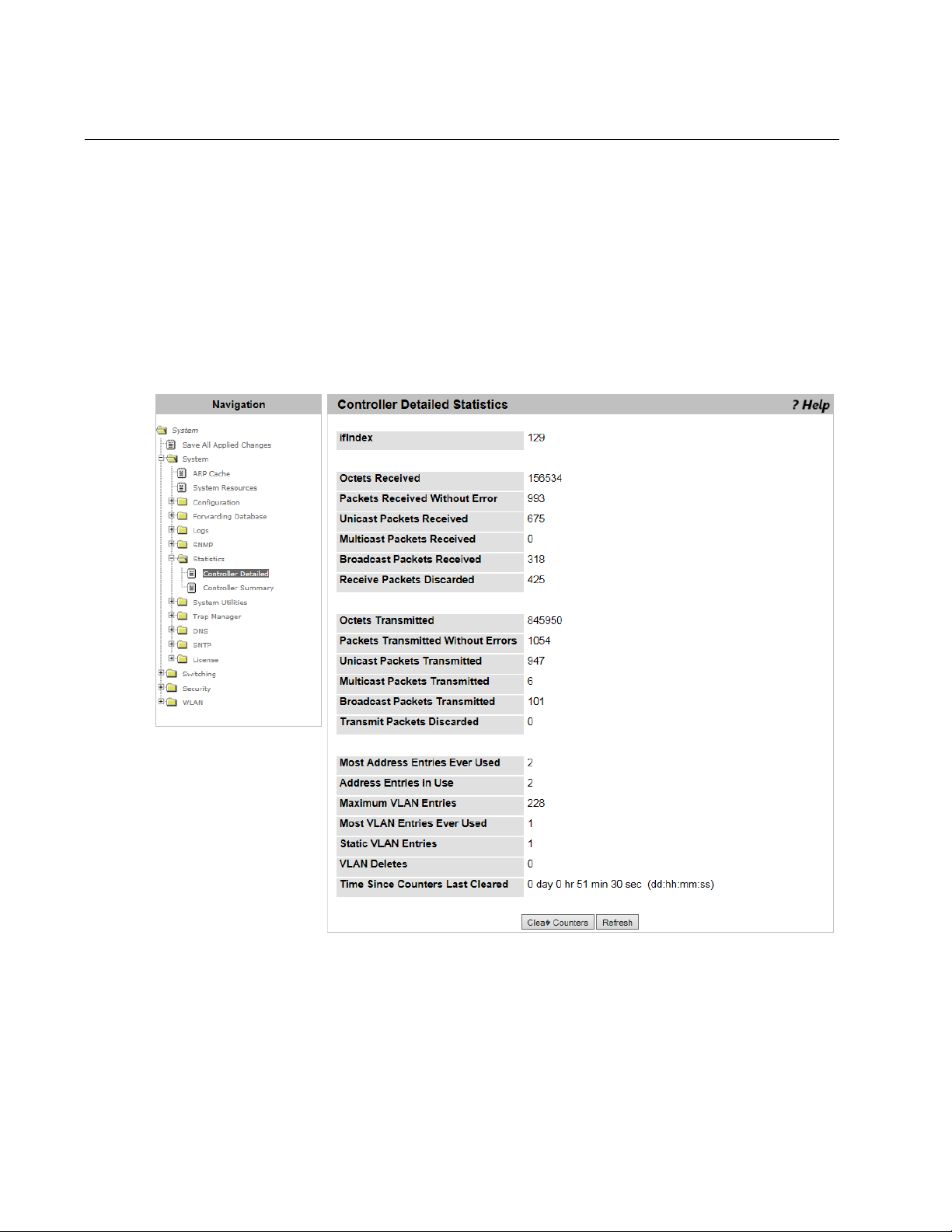
AT-UWC WLAN Controller Web GUI User’s Guide
Controller Detailed Statistics
From the Controller Detailed Statistics page, you can view statistics data
about the activities of WLAN Controller.
To view statistics information, do the following:
1. From the Navigation pane, go to System > Statistics > Controller
Detailed.
The Controller Detailed Statistics page is displayed as shown in
Figure 46.
78
Figure 46. Controller Detailed Statistics Page
2. Observed the fields described in Table 16 on page 79.
Page 79

Chapter 2: System
.
Table 16. Statistics Controller Detail
Field Description
ifIndex Displays the value of the interface index.
Octets Received Displays the number of received octets, including
FCS and excluding the frame bit.
Packets Received
Without Error
Unicast Packets
Displays the number of received broadcast and
multicast packets without errors.
Displays the number of received unicast packets.
Received
Multicast Packets
Displays the number of received multicast packets.
Received
Broadcast Packets
Displays the number of received broadcast packets.
Received
Receive Packets
Discarded
Displays the number of the received packets that
were discarded, excluding packets with an error. A
packet can be discarded due to a lack of buffer
space.
Octets Transmitted Displays the number of transmitted octets including
frame bits.
Packets
Displays the number of transmitted packets.
Transmitted Without
Errors
Unicast Packets
Transmitted
Displays the number of requested unicast packets
including the packets that were not transmitted or
discarded in the lower layer.
Multicast Packets
Transmitted
Displays the number of requested multicast packets
including the packets that were not transmitted or
discarded in the lower layer.
Broadcast Packets
Transmitted
Displays the number of requested broadcast
packets including the packets that were not
transmitted or discarded in the lower layer.
Transmit Packets
Discarded
Displays the number of the transmitted packets that
were discarded, excluding packets with an error. A
packet can be discarded due to a lack of buffer
space.
Most Address
Entries Ever Used
Displays the maximum number of the forwarding
database entries that were learned since the last
time system was rebooted.
79
Page 80

AT-UWC WLAN Controller Web GUI User’s Guide
Field Description
Table 16. Statistics Controller Detail (Continued)
Address Entries in
Use
Maximum VLAN
Entries
Most VLAN Entries
Used
Displays the number of entries in the forwarding
database at this moment.
Displays the maximum number of VLAN’s that the
system is allowed to have.
Displays the number of VLAN’s that are active since
the last time the system was rebooted.
Static VLAN Entries Displays the number of VLAN’s that were statically
created and are currently active.
VLAN Deletes Displays the number of VLAN’s that were statically
created, then deleted.
Time Since Counter
Last Cleared
Displays the time passed since the statistics data
was cleared.
3. Click one of the following buttons if necessary:
Clear Counters — Clears the counters.
Refresh — Displays the most recent statistics data.
80
Page 81

Controller Statistics Summary
From the Controller Statistics Summary page, you can view statistics data
about the activities of WLAN Controller. This page displays the subset of
the items displayed on the Controller Detailed Statistics page.
To view statistics information, do the following:
1. From the Navigation pane, go to System > Statistics > Controller
Summary.
The Controller Summary page is displayed as shown in Figure 47.
Chapter 2: System
Figure 47. Controller Statistics Summary Page
2. Observed the fields. The fields are explained in Table 16 on page 79.
3. Click one of the following buttons as needed:
Clear Counters — Clears the counters.
Refresh — Displays the most recent statistics data.
81
Page 82

AT-UWC WLAN Controller Web GUI User’s Guide
Note
Caution
System Reset
From the System Reset page, you can reset or shut down the WLAN
Controller.
To reboot the AT-UWC WLAN Controller from a PC-based server,
press Ctrl+Alt+Delete keys from the keyboard of the server.
To reset or shut down the system, do the following:
1. From the Navigation pane, go to System > System Utilities > System
Reset.
The System Reset page is displayed as shown in Figure 48.
82
Figure 48. System Reset Page
When resetting or shutting down the WLAN Controller, you lose your
unsaved changes. To save your changes to the startup
configuration file, see “Save All Applied Changes” on page 39.
2. Click one of the following buttons:
Reset — Power-cycles the WLAN Controller device.
Shutdown — Turns off the WLAN Controller device.
Page 83

Reset Configuration To Default
From the Reset Configuration To Default page, you can restore the default
settings to the WLAN Controller.
Chapter 2: System
Guidelines for
Resetting the
Configuration
Resetting the
Configuration
Here are the guidelines when you reset the configuration to the default
settings:
Since the IP address is reset to 192.168.1.1, you lose the
connection if the IP address was changed.
The password for the manager account is reset to “friend.”
Licenses are not deleted.
To restore the default settings to the WLAN Controller system, do the
following:
1. From the Navigation pane, go to System > System Utilities > Reset
Configuration To Default.
The Reset Configuration To Default page is displayed as shown in
Figure 49.
Figure 49. Reset Configuration To Default Page
2. Click Reset.
The Confirm Reset Configuration To Defaults page is displayed.
83
Page 84

AT-UWC WLAN Controller Web GUI User’s Guide
3. Click one of the following options:
Yes - Resets the configuration to the default settings.
No - Cancels the operation.
84
Page 85

Erase Startup Configuration File
From the Erase Startup Configuration File page, you can delete the startup
configuration file stored in the WLAN Controller. The startup configuration
file is a file that includes the current saved settings, which the WLAN
Controller loads when it reboots.
Chapter 2: System
Guidelines for
Erasing the
Startup
Configuration
File
Deleting the
Startup
Configuration
File
Here are the guidelines for erasing the startup configuration file:
The WLAN Controller keeps operating based on the settings on the
running configuration file unless the system resets.
Licenses are not deleted.
The image files downloaded from “Network Visualization
Downloaded Image,” are not deleted.
To delete the startup configuration file, do the following:
1. From the Navigation pane, go to System > System Utilities > Erase
Startup Configuration File.
The Erase Startup Configuration File page is displayed as shown in
Figure 50.
Figure 50. Erase Startup Configuration File Page
2. Click Erase.
The Confirm Erase Startup Configuration File page is displayed.
85
Page 86

AT-UWC WLAN Controller Web GUI User’s Guide
3. Click one of the following options:
Yes - Erases the startup configuration file.
No - Cancels the operation.
86
Page 87

Reset Passwords to Defaults
Note
From the Reset Passwords to Defaults page, you can reset the password
of the manager account to the default password “friend.”
The guest account is not supported for the current version. See
“User Accounts Configuration” on page 50.
To restore the default password of the manager account, do the following:
1. From the Navigation pane, go to System > System Utilities > Reset
Passwords to Defaults.
The Reset Passwords to Defaults page is displayed as shown in
Figure 51.
Chapter 2: System
Figure 51. Reset Passwords to Defaults Page
2. Click Reset.
The password of the manager account is set to “friend.”
87
Page 88

AT-UWC WLAN Controller Web GUI User’s Guide
Download File to Controller
From the Download File to Controller page, you can transfer a file from the
TFTP server to the WLAN Controller.
To transfer a file from the TFTP server to the WLAN Controller, do the
following:
1. From the Navigation pane, go to System > System Utilities >
Download File to Controller.
The Download File to Controller page is displayed as shown in
Figure 52.
88
Figure 52. Download File to Controller Page
2. Specify the following fields in Table 17 on page 89.
Page 89

Chapter 2: System
.
Table 17. Download File to Controller
Field Description
File Type Select one of the following file types:
Configuration: Specifies a binary file that
includes graphics used for the captive portal
and network visualization.
Text Configuration: Specifies a startup
configuration file.
Transfer Mode Displays the protocol TFTP, which is the only option.
Server
Select one of the following types:
Address Type
IPv4: Specifies a TFTP server with its IPv4
address.
DNS: Specifies a TFTP server with its host
name.
Server
Address
Enter the IPv4 address or host name of the TFTP
server.
Transfer File
Path
Transfer File
Name
Start File
Enter the path of the file on the TFTP server. The path
must be up to 32 characters.
Enter the name of the file you want to download from
the TFTP server to the WLAN Controller system.
Check the checkbox to start the file transfer.
Transfer
File Transfer
Displays the progress of the file transfer.
Status
3. Click Submit.
The status is displayed in the File Transfer Status field.
89
Page 90

AT-UWC WLAN Controller Web GUI User’s Guide
Upload File from Controller
From the Upload File from Controller page, you can transfer a file from the
WLAN Controller to a TFTP server.
To transfer a file from the WLAN Controller to a TFTP server, do the
following:
1. From the Navigation pane, go to System > System > System Utilities >
Upload File from Controller.
The Upload File from Controller page is displayed as shown in
Figure 53.
90
Figure 53. Upload File from Controller Page
2. Specify the following fields in Table 18 on page 91.
Page 91

Chapter 2: System
.
Table 18. Upload File from Controller
Field Description
File Type Select one of the following file types:
Configuration: Specifies a binary file that
includes graphics used for the captive portal
and network visualization.
Text Configuration: Specifies a startup
configuration file.
Error Log: Not supported.
Buffered Log: Specifies a buffered log file.
Persistent Log: Specifies a persistent log file
including all persistent log messages.
Diagnosis Log: Specifies a diagnosis log file.
ValidAccessPoint DB: Not supported.
Transfer Mode Displays the protocol TFTP, which is the only option.
Server
Select one of the following types:
Address Type
IPv4: Specifies a TFTP server with its IPv4
address.
DNS: Specifies a TFTP server with its host
name.
Server
Address
Transfer File
Path
Transfer File
Name
Enter the IPv4 address or host name of the TFTP
server.
Enter the location where you place the file on the
TFTP server. The maximum length is 32 characters
Enter the name of the file that you upload from the
WLAN Controller. Spaces and special characters are
not allowed.
Start File
Check the checkbox to start the file transfer.
Transfer
File Transfer
Displays the progress of the file transfer.
Status
3. Click Submit.
The status is displayed in the File Transfer Status field.
91
Page 92

AT-UWC WLAN Controller Web GUI User’s Guide
HTTP File Download
From the HTTP File Download page, you can transfer a file from your
management workstation to the WLAN Controller.
To transfer a file from your management workstation to the WLAN
Controller, do the following:
1. From the Navigation pane, go to System > System Utilities > HTTP
File Download.
The HTTP File Download page is displayed as shown in Figure 54.
92
Figure 54. HTTP File Download Page
2. Specify the following fields in Table 19 on page 93.
Page 93

Chapter 2: System
.
Table 19. HTTP File Download
Field Description
File Type Select one of the following file types:
Configuration: Specifies a binary file
that includes graphics used for the
captive portal and network
visualization.
Text Configuration: Specifies a
startup configuration file.
Select File Click Browse and specify the file to download.
File Download Status Displays the progress of the file download.
3. Click Start File Transfer.
The status is displayed in the File Download Status field.
93
Page 94

AT-UWC WLAN Controller Web GUI User’s Guide
Note
Software Upgrade
From the Software Upgrade page, you can upgrade management
software from your management workstation to the WLAN Controller.
After downloading management software, you must reset the WLAN
Controller to load the software. See “System Reset” on page 82.
Guideline for
upgrading
Management
Software
Upgrading
Management
Software
Here are the guidelines for upgrading management software
After downloading management software, you must reboot the
WLAN Controller to load the software. See “System Reset” on
page 82.
The startup configuration stays the same after the system was
upgraded.
You cannot install older versions of software.
The file name of the management software is not allowed to
include space or symbols.
To download management software, do the following:
1. From the Navigation pane, go to System > System Utilities > Software
Upgrade.
The Software Upgrade page is displayed as shown in Figure 55 on
page 95.
94
Page 95

Chapter 2: System
Figure 55. Software Upgrade Page
2. Specify the following fields in Table 20.
.
Table 20. Software Upgrade
Field Description
Running Version Displays the version of the management
software currently running.
Installed File Version Displays the version of the management
software downloaded to the WLAN Controller.
Select File Click Browse and select a management
software file.
3. Click Start File Transfer.
The specified management software is downloaded.
95
Page 96

AT-UWC WLAN Controller Web GUI User’s Guide
Ping
From the Ping page, you can test network connections between the
WLAN Controller and the destination using the ping utility.
To test network connections using the ping utility, do the following:
1. From the Navigation pane, go to System > System Utilities > Ping.
The Ping page is displayed as shown in Figure 56.
96
Figure 56. Ping Page
2. Specify the following fields in Table 21.
.
Table 21. Ping
Field Description
Host Name/IP
Address
Specifies the destination with the host name or
IPv4 address.
Count Specifies how many time to send request packets.
The default is 1 time.
Interval Specifies time in seconds to wait before sending
another request packet.
Page 97

Chapter 2: System
Table 21. Ping (Continued)
Field Description
Size Specifies the size of a request packet in bytes.
Ping Displays the results of executing the ping utility.
3. Click Submit.
97
Page 98

AT-UWC WLAN Controller Web GUI User’s Guide
TraceRoute
From the TraceRoute page, you can trace the path that an IP packet takes
to reach the destination.
To trace the path to the destination using the traceroute utility, do the
following:
1. From the Navigation pane, go to System > System Utilities >
TraceRoute.
The TraceRoute page is displayed as shown in Figure 57.
98
Figure 57. TraceRoute Page
2. Specify the following fields in Table 22.
.
Table 22. TraceRoute
Field Description
Host Name/IP
Address
Specifies the destination with the host name or
IPv4 address.
Page 99

Chapter 2: System
Table 22. TraceRoute (Continued)
Field Description
Probes per Hop Specifies the number of probe packets per hop.
The default setting is 3 packets.
Max TTL Specifies the maximum number of hops to allow
probe packets to travel. Time to live (TTL) is
specified by hop counts. The default setting is 30
hops.
InitTTL Specifies the number set in the initial TTL. The
default setting is 1.
MaxFail Specifies the number of attempts to send a probe
packet. The default setting is 5 times.
Interval(secs) Specifies the time period in seconds to wait before
sending another packet. The default value is 3
seconds.
Port Specifies the UDP port number used for probe
packets. The default port number is 33434.
Size Specifies the size of a probe packet in bytes.
TraceRoute Displays the results of executing the TraceRoute
utility.
3. Click Submit.
99
Page 100

AT-UWC WLAN Controller Web GUI User’s Guide
Trap Flags
From the Trap Flags page, you can enable or disable the system to send
traps when the SNMP authentication failed or the link status changed.
To enable or disable sending traps, do the following:
1. From the Navigation pane, go to System > Trap Manager > Trap
Flags.
The Trap Flags page is displayed as shown in Figure 58.
Figure 58. Trap Flags Page
2. Specify the following fields in Table 23.
.
Table 23. Trap Flags
Field Description
Authentication Select one of the options:
Enable: The system sends traps when the
SNMP authentication failed.
Disable: The system does not send traps
when the SNMP authentication failed.
Link Up/Down Select one of the options;
Enable: The system sends traps when the link
status of the Ethernet port on the WLAN
Controller changed or when the status of a
managed AP changed.
Disable: The system does not send traps
when the link status of the Ethernet port on
the WLAN Controller changed or when the
status of managed AP changed.
100
 Loading...