

Page 1

AT-UWC Wireless LAN Controller
Software Version
Installation Guide
This Installation Guide is an introductory guide to help you start the
software-based AT-UWC Wireless LAN Controller. It describes how to run
the AT-UWC-Install program on a PC-based server or virtual machine,
start and end a management session, and modify the settings on the
AT-UWC Wireless LAN Controller.
This document contains the following topics:
“Overview” on page 2
“Preparing the Installation of the AT-UWC WLAN Controller” on page 3
613-001874 Rev. A
“Installing the AT-UWC WLAN Controller” on page 7
“Preparing the Management Workstation” on page 10
“Starting a Management Session” on page 11
“Registering the License Key” on page 12
“Changing the IP Address” on page 15
“Enabling JavaScript” on page 19
“Modifying the Settings” on page 22
“Saving the Changes” on page 26
“Using Online Help” on page 28
“Ending a Management Session” on page 32
Page 2

AT-UWC Wireless LAN Controller
Overview
The AT-UWC Wireless LAN (WLAN) Controller is a software-based
management tool that allows you to control Allied Telesis TQ series
wireless access point devices. The AT-UWC-Install is a program that
installs AT-UWC WLAN Controller onto a PC-based server or virtual
machine.
To start the AT-UWC WLAN Controller, first, install the AT-UWC WLAN
Controller onto a server. To activate the WLAN controller, register the
license key through the web interface from a management workstation.
Installing the
AT-UWC WLAN
Controller
To install the AT-UWC WLAN Controller, follow the steps below:
1. Obtain the AT-UWC-Install zip file and create an installation DVD or
CD.
See “Preparing the Installation of the AT-UWC WLAN Controller” on
page 3.
2. Install the AT-UWC WLAN Controller from the installation DVD or CD
onto a server.
See “Installing the AT-UWC WLAN Controller” on page 7.
3. Prepare the management workstation.
See “Preparing the Management Workstation” on page 10.
4. Start a management session from the management workstation.
“Starting a Management Session” on page 11.
5. Register the license key to activate the AT-UWC WLAN Controller.
See “Registering the License Key” on page 12.
Configuring the
AT-UWC WLAN
Controller
2
After you installed the AT-UWC-Install program and license key, you want
to configure the AT-UWC WLAN Controller to meet your requirements.
To configure the AT-UWC WLAN Controller, see the following procedures:
“Starting a Management Session” on page 11
“Modifying the Settings” on page 22
“Saving the Changes” on page 26
“Using Online Help” on page 28
“Ending a Management Session” on page 32
Page 3
Preparing the Installation of the AT-UWC WLAN Controller
Before installing the AT-UWC WLAN Controller, you must obtain the
AT-UWC-Install ISO file and create an AT-UWC-Install DVD or CD. An
ISO file is an image file for a CD or DVD disc. To prepare installation, do
the following:
1. “Downloading the AT-UWC-Install ISO File,” next
2. “Creating the AT-UWC-Install DVD or CD” on page 6
Installation Guide
Downloading the
AT-UWC-Install
ISO File
Allied Telesis provides the AT-UWC-Install ISO file from the Restricted
Software Downloads website.
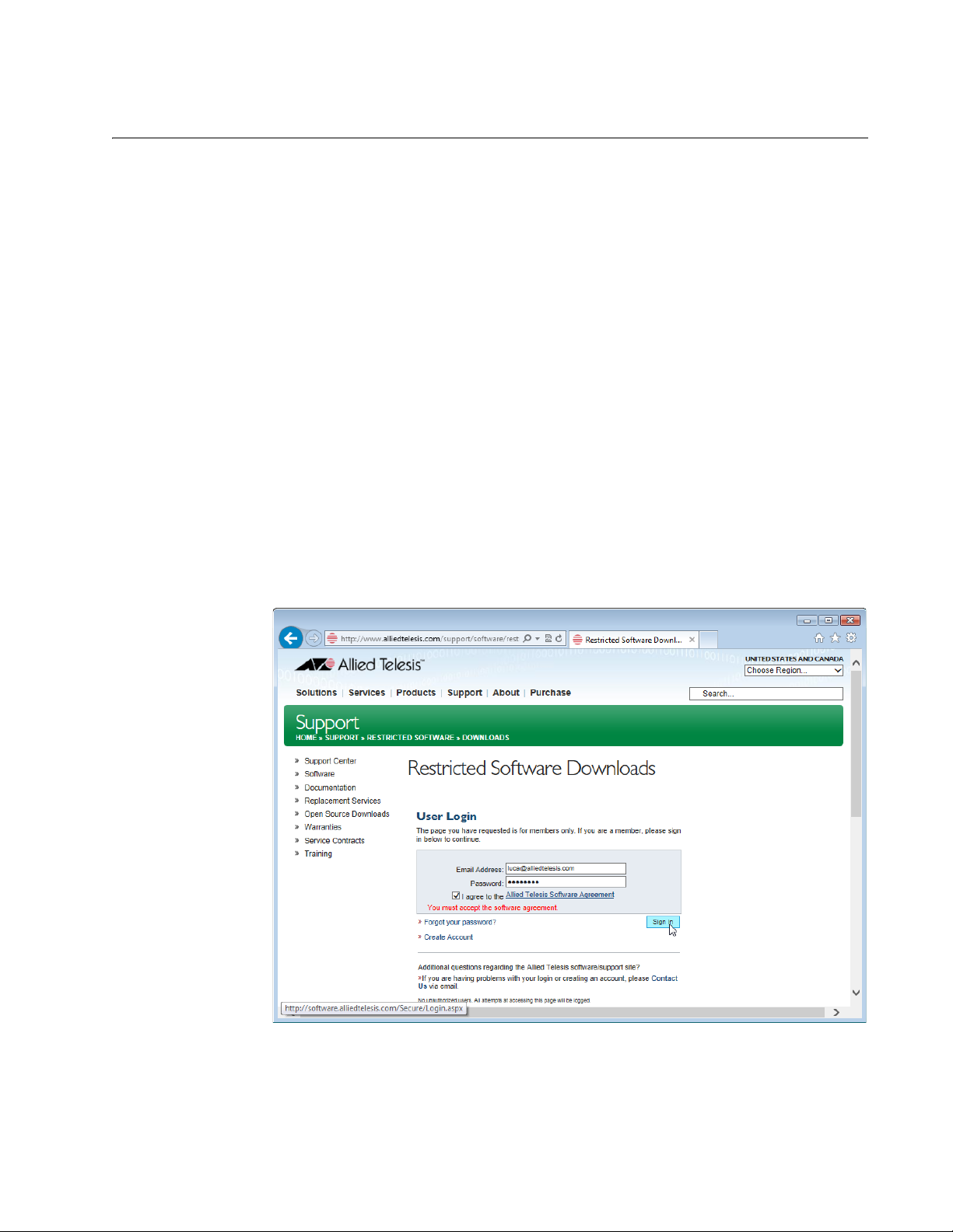
To download the AT-UWC-Install ISO file, do the following:
1. Open a web browser, such as Internet Explorer or FireFox, on your
system and enter the following:
http://www.alliedtelesis.com/support/software/restricted
The browser prompts you to enter a user name and password as
shown in Figure 1.
Figure 1. Restricted Software Downloads Login Page
2. Enter your email address and password.
3
Page 4
AT-UWC Wireless LAN Controller
If you do not have an account, create one. Click Create Account and
follow the instructions.
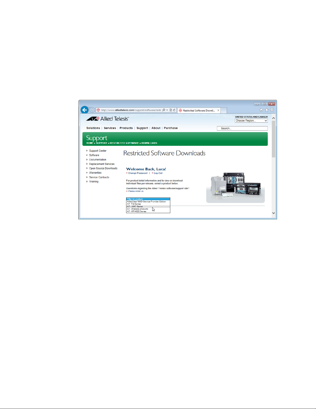
3. Read the Allied Telesis Software Agreement.
If you agree, check the checkbox and press Sign in.
An example of the Restricted Software Downloads Welcome page is
displayed as shown in Figure 2.
Figure 2. Restricted Software Downloads Welcome Page
4. Select AT-UWC Series from the select box.
The AT-UWC page is displayed as shown in Figure 3 on page 5.
4
Page 5
Installation Guide
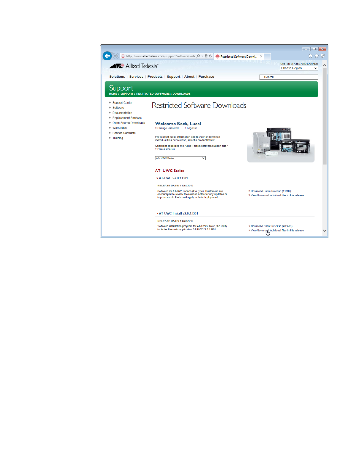
Figure 3. Restricted Software Downloads AT-UWC Page
5. Click View/download individual files in this release under the
AT-UWC-Install v2.0.1.B01 section.
The available AT-UWC files are listed as shown in Figure 4 on page 6.
5
Page 6
AT-UWC Wireless LAN Controller
Creating the
AT-UWC-Install
DVD or CD
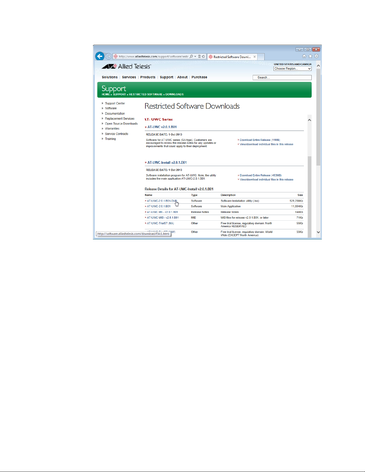
Figure 4. Restricted Software Downloads AT-UWC Page
6. Select AT-UWC-2.0.1.B01-DVD from the list and save it onto your
system.
To create an AT-UWC-Install DVD or CD, you must burn or write the ISO
image to a DVD or CD. Ensure that you have a program to burn or write an
ISO file to a DVD or CD disc on your system.
The steps to burn or write a DVD or CD depend upon the program. Refer
to the instructions for your particular program.
6
Page 7

Installing the AT-UWC WLAN Controller
Note
Caution
To install AT-UWC WLAN Controller onto a server, you must boot the
server from the DVD or CD that the AT-UWC-Install ISO image is written
to.
You can install the AT-UWC WLAN Controller onto a PC-based server or a
virtual machine.
Installation Guide
Requirements for
a PC-based
Server
Supported
Virtual Machine
Platforms
To install the AT-UWC WLAN Controller onto a PC-based server, the PC
must meet the following requirements:
3.10 GHz or faster x86 processor
1 Gigabyte or larger RAM (4 Gigabyte is recommended)
80 Gigabyte or larger Hard Disk
DVD ROM
Gigabit Ethernet Network Interface Card compatible with the
IEEE 802.1q standard
Monitor
Keyboard
The following list shows the supported virtual machine platforms:
VMware vSphere (v5.1)
Microsoft Windows Server 2008 R2 (Hyper-V 2.0)
Microsoft Windows 8 (Hyper-V 2.0)
The procedures for installing the AT-UWC WLAN Controller onto a
virtual machine vary depending upon your virtual machine settings.
Refer to “Installing the AT-UWC WLAN Controller onto a PC,” next.
Installing the
AT-UWC WLAN
Controller onto a
PC
To install the AT-UWC WLAN Controller onto a PC, do the following:
1. Connect a monitor and keyboard to a PC.
2. Power on the PC and monitor.
When you boot a PC-based server with the DVD or CD, the
installation program deletes all the data in the HDD.
7
Page 8
AT-UWC Wireless LAN Controller
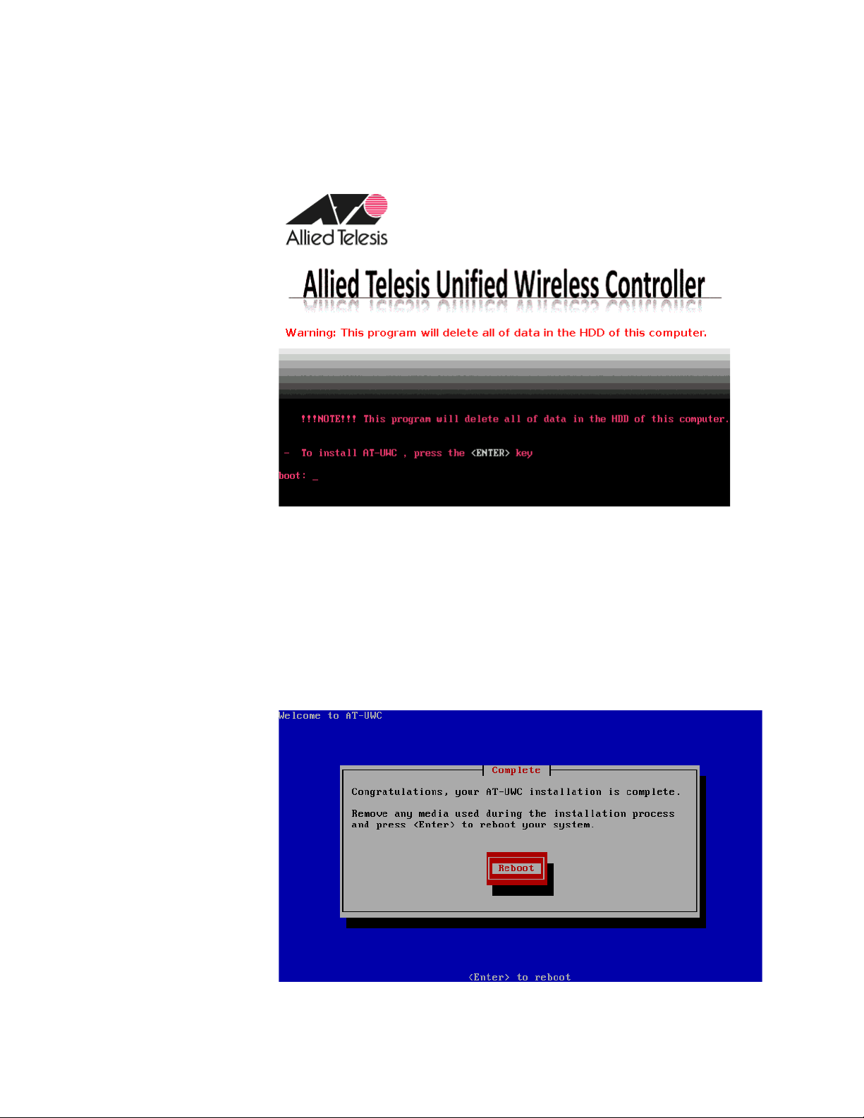
3. Insert the AT-UWC-Install DVD or CD in the DVD driver on the PC.
The Allied Telesis Unified Wireless Controller installation program
screen is displayed as shown in Figure 5.
Figure 5. Allied Telesis Unified Wireless Controller installation Screen
4. Press the Enter key.
The installation program starts to install the AT-UWC application,
including an operating system called CentOS. It may take five or six
minutes.
When the installation is complete, the screen appears as shown in
Figure 6. The DVD tray may eject automatically.
Figure 6. Allied Telesis Unified Wireless Controller installation Complete
8
Page 9

5. Remove the DVD from the tray.
Meanwhile, the server reboots and starts the AT-UWC WLAN
Controller.
Installation Guide
9
Page 10
AT-UWC Wireless LAN Controller
Note
Note
Preparing the Management Workstation
To register the license key or configure the AT-UWC WLAN Controller,
you must have a management workstation to access the AT-UWC WLAN
Controller.
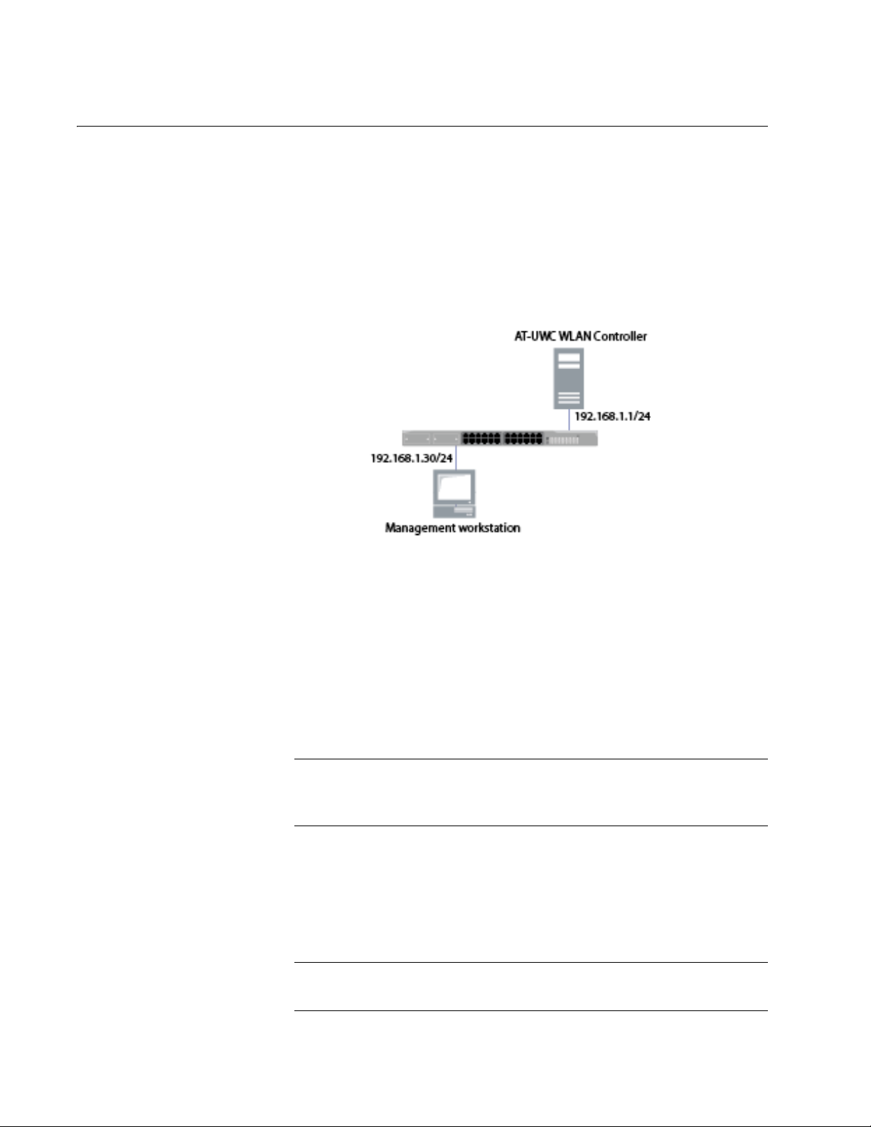
The management workstation is a computer that you use to manage the
AT-UWC WLAN Controller. The management workstation must be
connected to the network that the AT-UWC WLAN Controller server
belongs to. See an example shown in Figure 7.
Figure 7. AT-UWC WLAN Controller and Management Workstation
The AT-UWC WLAN Controller server has the following default IP address
and subnet mask assigned:
192.168.1.1/255.255.255.0
For the first time you access the AT-UWC WLAN Controller server, your
management workstation must have an IP address in the following range:
192.168.1.2 to 192.168.1.254
To change the IP address of the management workstation, see
“Changing the IP Address” on page 15.
The management workstation must have the following applications:
Windows Internet Explorer 7 or 8 with Java Plug-in
Oracle Java Runtime Environment Version 6
JavaScript
To enable JavaScript, see “Enabling JavaScript” on page 19.
10
Page 11

Starting a Management Session
The AT-UWC WLAN Controller is managed from the management
workstation through the web interface.
To start a management session of the AT-UWC WLAN Controller, do the
following:
1. Login to the management workstation.
If you do not have a management workstation, see “Preparing the
Management Workstation” on page 10.
2. Open Internet Explorer 7 or 8, and enter the IP address of the
AT-UWC WLAN Controller server.
Installation Guide
The default IP address is
192.168.1.1.
3. Enter the user name and password. See Figure 8.
The following are the default settings:
User name: manager
Password: friend
Figure 8. AT-UWC WLAN Controller Login Screen
4. Press Login.
11
Page 12

AT-UWC Wireless LAN Controller
Registering the License Key
Registering the license key activates the AT-UWC WLAN Controller. For
the first time you login to the AT-UWC WLAN Controller, you must register
the license key.
License Key The license key is formed with the following two information:
A serial number
An authentication key
When you purchase the AT-UWC WLAN Controller software, you obtain a
license key that allows you to control 10 access point devices. To control
more access point devices, you can purchase additional license key.
30-day Free Trial
License
Registering the
License Key
Allied Telesis offers a 30-day free trial for new users. Two types of free trial
license keys are available:
AT-UWC-TrialST (NA): for users in North America
AT-UWC-TrialST (WW): for users worldwide except North America
You can download a free trial license from Allied Telesis Restricted
Software Downloads website. To obtain a free trial license, see
“Downloading the AT-UWC-Install ISO File” on page 3 and follow the
instructions. On step 6, save AT-UWC-TrialST_(NA).pdf or
AT-UWC-TrialST_(WW).pdf.
To register the license key, do the following:
1. Start a management session.
See “Starting a Management Session” on page 11.
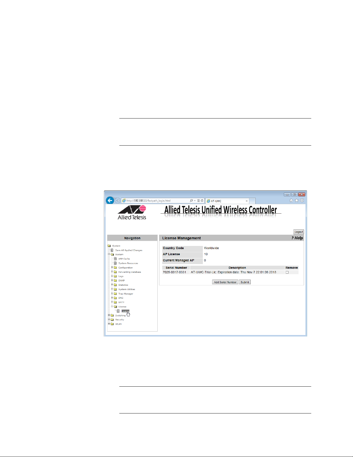
2. From the Navigation panel on the left, go to System > License >
License.
The License screen is displayed as shown in Figure 9 on page 13.
12
Page 13

Installation Guide
Figure 9. AT-UWC WLAN Controller License Screen
3. Press Add Serial Number.
The Add Serial Number screen is displayed as shown in Figure 10.
Figure 10. AT-UWC WLAN Controller Serial Number Screen
13
Page 14
AT-UWC Wireless LAN Controller
Note
Note
4. Enter your serial number and authentication key.
5. Press Submit.
6. From the Navigation panel on the left, go to System Utilities >
System Reset.
7. Click Reset.
The AT-UWC WLAN Controller server reboots.
To reboot the AT-UWC WLAN Controller from a PC-based server,
press Ctrl+Alt+Delete keys from the keyboard of the server.
8. From the Navigation panel on the left, go to System > License >
License.
The license Management screen appears as shown in Figure 11.
Figure 11. AT-UWC WLAN Controller License Management Screen
9. Confirm that the license key is properly registered.
10. If you want to add another license key, repeat steps 2 to 5.
When you add another license key, you do not need to reboot the
AT-UWC WLAN Controller server.
14
Page 15

Changing the IP Address
When you access the AT-UWC WLAN Controller from the management
workstation, it must have an IP address form the same network as the
AT-UWC WLAN Controllerserver.
The procedures for changing the IP address is slightly different among
Windows Operating Systems. The following is the procedures using
Windows 7 as an example.
To change the IP address of a PC installed on Windows 7, do the
following:
1. Click Control Panel from the Start button.
The control panel appears as shown in Figure 12.
Installation Guide
Figure 12. Control Panel
2. Click Category at the upper right corner of the window and select
Large icons.
Control Panel displays items with large icons as shown in Figure 13 on
page 16.
15
Page 16

AT-UWC Wireless LAN Controller
Figure 13. Control Panel with Large Icons
3. Click Network and Sharing Center.
The Basic Network Information window appears as shown in
Figure 14.
16
Figure 14. Network Information Window
Page 17

4. Click Local Area Connection.
The Local Area Connection Status window appears as shown in
Figure 15.
Installation Guide
Figure 15. Local Area Connection Status Window
5. Click the Properties button at the bottom.
The Local Area Connection Properties window appears as shown in
Figure 16.
Figure 16. Local Area Connection Properties Window
17
Page 18
AT-UWC Wireless LAN Controller
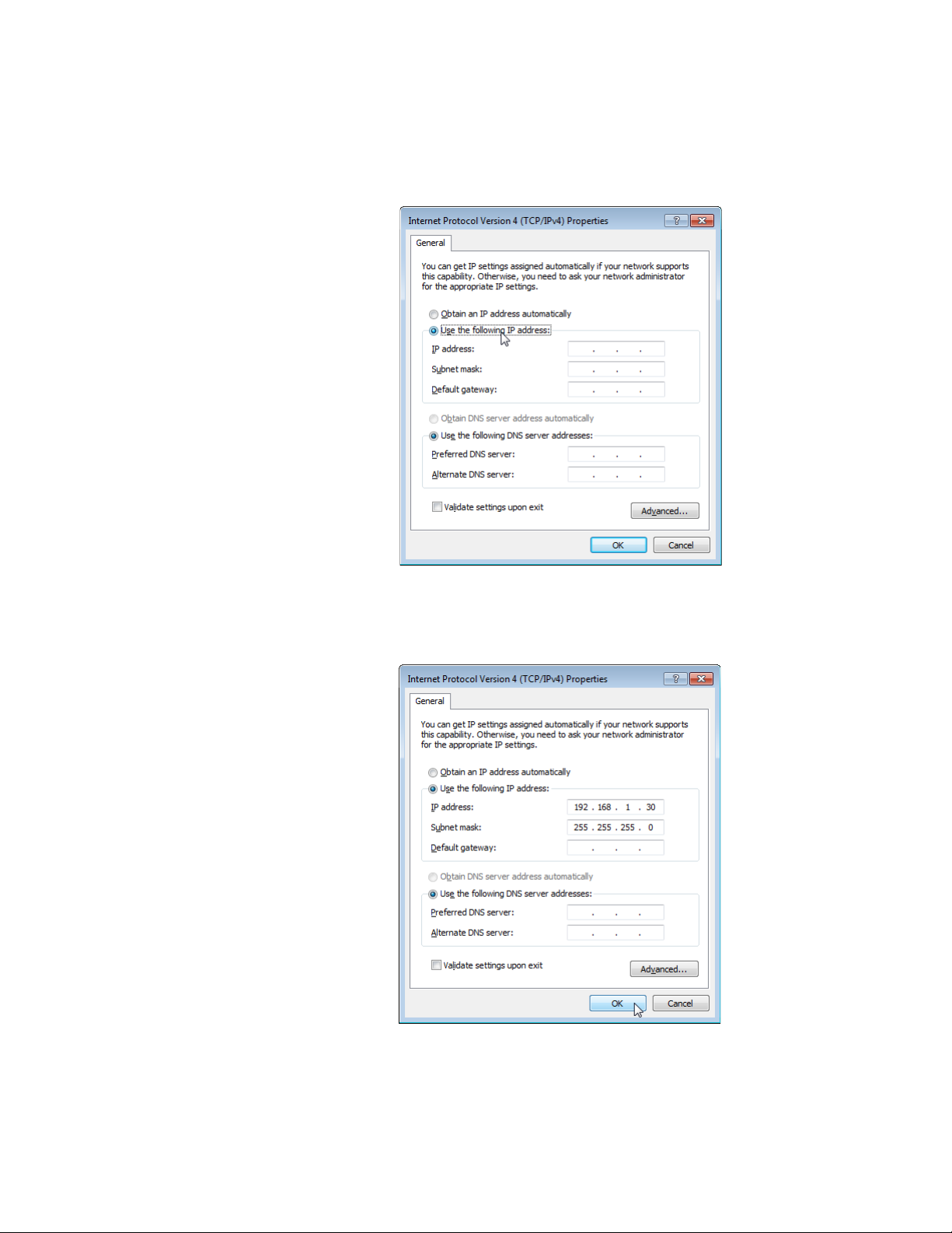
6. Double-click Internet Protocol Version 4 (TCP/IPv4).
The Internet Protocol Version 4 (IPv4) Properties window appears as
shown in Figure 17.
Figure 17. IPv4 Properties Window
7. Enter the IP address and Subnet mask. See Figure 18.
18
Figure 18. IPv4 Properties Window Example
8. Click OK.
Page 19

Enabling JavaScript
Note
To access the AT-UWC WLAN Controller, you must enable JavaScript for
your Windows Internet Explorer. You can enable JavaScript only when
accessing the AT-UWC WLAN Controller.
To enable JavaScript only for the AT-UWC WLAN Controller, do the
following:
1. Open the Windows Internet Explorer.
2. Click Tools from the menu bar.
3. Select Internet options from the drop-down menu.
Installation Guide
When JavaScript is already enabled, you do not have to change the
setting.
The Internet Options window pops up.
4. Click the Security tab on the Internet Options window.
The Internet Options window appears as shown in Figure 19.
Figure 19. Internet Options Window Security Tab
19
Page 20

AT-UWC Wireless LAN Controller
Note
5. Select the Trusted sites icon in the box and press the Sites button.
The Trusted sites window appears as shown in Figure 20.
Figure 20. Trusted Sites Window
6. Enter the IP address of the AT-UWC WLAN Controller server and
check the checkbox of “Require server verification (https:) for all sites
in this zone.
By the default, the IP address of the AT-UWC WLAN Controller
server 192.168.1.1.
7. Click Add.
The Security Settings Internet Zone window appears as shown in
Figure 21 on page 21.
20
Page 21

Installation Guide
Figure 21. Security Settings Window
8. Change the setting of Active scripting to Enable.
9. Click OK.
10. Restart the Internet Explorer.
JavaScript is enabled only when you access the AT-UWC WLAN
Controller.
21
Page 22

AT-UWC Wireless LAN Controller
Note
Modifying the Settings
The AT-UWC WLAN Controller allows you to modify the settings on the
AT-UWC WLAN Controller to meet your requirements. This section shows
how to modify and save the setting of the default gateway as an example
and view the AP Profiles page to see tabs and sub-tabs.
To assign a default gateway, do the following:
1. Start a management session. See “Starting a Management Session”
on page 11.
When you press the Submit button, your changes are stored in the
running configuration. The settings in the running configuration are
deleted when the AT-UWC WLAN Controller reboots. If you want to
keep your changes, see “Saving the Changes” on page 26.
2. Click the + icon next to the Configuration folder.
The folder expands as shown in Figure 22.
Figure 22. AT-UWC WLAN Controller Screen
22
Page 23

Installation Guide
3. Click the Network Connectivity item on the expanded list.
The Network Connectivity Configuration screen is displayed as shown
in Figure 23.
Figure 23. AT-UWC WLAN Controller Network Connectivity Screen
4. Enter a default gateway address.
When you change the setting, the message, “System has unsaved
changes” appears under the Allied Telesis logo on the screen as
shown in Figure 24 on page 24.
23
Page 24

AT-UWC Wireless LAN Controller
Note
Figure 24. AT-UWC WLAN Controller Network Connectivity Configuration
5. Click Submit.
The change is saved in the running configuration.
The change is applied immediately; however, you lose the change
when the server reboots. To save your changes to the startup
configuration, See “Saving the Changes” on page 26.
To view a page with multiple tabs and sub-tabs, do the following:
1. Click the + icon next to the WLAN folder.
The folder expands and list items inside the folder.
2. Click the + icon next to the Advanced Configuration folder.
3. Select the AP Profiles item on the expanded list.
AP profile names are listed.
4. Select one of the AP profile names on the list.
5. Click the VAP sub-tab under the Default tab.
24
Page 25

Installation Guide
Note
The Access Point Profile VAP Configuration screen is displayed as
shown in Figure 25.
Figure 25. AT-UWC WLAN Controller AP Profile Screen
This screen has multiple tabs, such as Summary and Default. Each tab
has multiple sub-tabs. You must press the Submit button to save your
changes to the running configuration before you go to another page
using a tab or sub-tab.
If you do not press the Submit button before moving to another
page, you lose the changes that you just made.
25
Page 26

AT-UWC Wireless LAN Controller
Saving the Changes
When you change settings of the AT-UWC WLAN Controller and click the
Submit button on each page, the changes are stored in the running
configuration. The settings in the running configuration are deleted when
the AT-UWC WLAN Controller reboots. You must save the changes to the
startup configuration if you want to keep the changes after the AT-UWC
WLAN Controller reboots.
To save the changes to the startup configuration, do the following:
1. Start a management session. See “Starting a Management Session”
on page 11.
The Allied Telesis Unified Wireless Controller starts as shown in
Figure 26.
26
Figure 26. AT-UWC WLAN Controller Screen
2. From the Navigation panel on the left, go to System > Save All
Applied Changes.
The Save All Applied Changes screen is displayed as shown in Figure
27 on page 27.
Page 27

Figure 27. AT-UWC WLAN Controller Save Changes Screen
3. Click Save.
The Confirmation window appears as shown in Figure 28.
Installation Guide
Figure 28. Confirmation Window
The changes are saved to the startup configuration.
27
Page 28

AT-UWC Wireless LAN Controller
Using Online Help
When you have a question about the AT-UWC WLAN Controller, the
Online Help can be a good place to look for your answer.
To access the Online Help, do the following:
1. Start a management session. See “Starting a Management Session”
on page 11.
The Allied Telesis Unified Wireless Controller screen is displayed as
shown in Figure 29.
28
Figure 29. AT-UWC WLAN Controller Screen
2. Click ?Help.
The Online Help is displayed shown in Figure 30 on page 29.
Page 29

Installation Guide
Figure 30. AT-UWC WLAN Controller Online Help
3. Click the TOC button at the lower left corner of the screen.
The Online Help Table of Contents is displayed shown in Figure 31 on
page 30.
29
Page 30
AT-UWC Wireless LAN Controller
Figure 31. AT-UWC WLAN Controller Online Help TOC
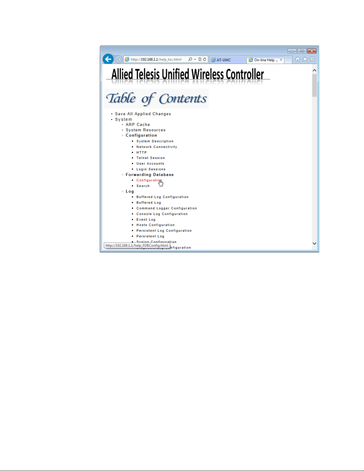
4. Click the Configuration on the Table of Contents for example.
The Online Help Configuration portion is displayed shown in Figure 32
on page 31.
30
Page 31

Installation Guide
Figure 32. AT-UWC WLAN Controller Online Help Example
31
Page 32

AT-UWC Wireless LAN Controller
Ending a Management Session
You can end a management session at any time during a management
session.
To end a management session, do the following:
1. Save the changes to the startup configuration.
See “Saving the Changes” on page 26. If you do not want to save your
changes, skip this step.
2. Click the Logout button on the right side of the screen.
See Figure 33 as an example.
32
Figure 33. AT-UWC WLAN Controller Screen
The management session ends.
Page 33

Installation Guide
Copyright © 2013 Allied Telesis, Inc.
All rights reserved. No part of this publication may be reproduced without prior written permission from Allied Telesis, Inc.
Microsoft and Internet Explorer are registered trademarks of Microsoft Corporation. Netscape Navigator is a registered
trademark of Netscape Communications Corporation. All other product names, company names, logos or other
designations mentioned herein are trademarks or registered trademarks of their respective owners.
Allied Telesis, Inc. reserves the right to make changes in specifications and other information contained in this document
without prior written notice. The information provided herein is subject to change without notice. In no event shall Allied
Telesis, Inc. be liable for any incidental, special, indirect, or consequential damages whatsoever, including but not limited to
lost profits, arising out of or related to this manual or the information contained herein, even if Allied Telesis, Inc. has been
advised of, known, or should have known, the possibility of such damages.
33
 Loading...