

Page 1
AT-DC2552XS
Layer 2 Data Center Switch
Management Software
Command Line Interface User’s Guide
AlliedWare Plus Version 2.5.1.1
613-001753 Rev. A
Page 2

Copyright
Copyright © 2013, Allied Telesis, Inc.
All rights reserved.
This product includes software licensed under the BSD License. As such, the following language applies for those
portions of the software licensed under the BSD License:
Redistribution and use in source and binary forms, with or without modification, are permitted provided that the following
conditions are met:
* Redistributions of source code must retain the above copyright notice, this list of conditions and the following
disclaimer.
* Redistributions in binary form must reproduce the above copyright notice, this list of conditions and the following
disclaimer in the documentation and/or other materials provided with the distribution.
* Neither the name of Allied Telesis, Inc. nor the names of the respective companies above may be used to endorse or
promote products derived from this software without specific prior written permission.
THIS SOFTWARE IS PROVIDED BY THE COPYRIGHT HOLDERS AND CONTRIBUTORS "AS IS" AND ANY
EXPRESS OR IMPLIED WARRANTIES, INCLUDING, BUT NOT LIMITED TO, THE IMPLIED WARRANTIES OF
MERCHANTABILITY AND FITNESS FOR A PARTICULAR PURPOSE ARE DISCLAIMED. IN NO EVENT
SHALL THE COPYRIGHT HOLDER OR CONTRIBUTORS BE LIABLE FOR ANY DIRECT, INDIRECT,
INCIDENTAL, SPECIAL, EXEMPLARY, OR CONSEQUENTIAL DAMAGES (INCLUDING, BUT NOT LIMITED
TO, PROCUREMENT OF SUBSTITUTE GOODS OR SERVICES; LOSS OF USE, DATA, OR PROFITS; OR
BUSINESS INTERRUPTION) HOWEVER CAUSED AND ON ANY THEORY OF LIABILITY, WHETHER IN
CONTRACT, STRICT LIABILITY, OR TORT (INCLUDING NEGLIGENCE OR OTHERWISE) ARISING IN ANY
WAY OUT OF THE USE OF THIS SOFTWARE, EVEN IF ADVISED OF THE POSSIBILITY OF SUCH DAMAGE.
Copyright 1989, 1991, 1992 by Carnegie Mellon University. Derivative Work - 1996, 1998-2000. Copyright 1996, 19982000 by The Regents of the University of California - All rights reserved. Copyright (c) 2001-2003 by Networks
Associates Technology, Inc. - All rights reserved. Copyright (c) 2001-2003 by Cambridge Broadband Ltd. - All rights
reserved. Copyright (c) 2003 by Sun Microsystems, Inc. - All rights reserved. Copyright (c) 2003-2005 by Sparta, Inc. All rights reserved. Copyright (c) 2004 by Cisco, Inc. and Information Network Center of Beijing University of Posts and
Telecommunications. - All rights reserved. Copyright (c) 2003 by Fabasoft R&D Software GmbH & Co KG - All rights
reserved. Copyright (c) 2004-2006 by Internet Systems Consortium, Inc. ("ISC") - All rights reserved. Copyright (c)
1995-2003 by Internet Software Consortium - All rights reserved. Copyright (c) 1992-2003 by David Mills - All rights
reserved. Copyright (c) 1995 by Tatu Ylonen <ylo@cs.hut.fi>, Espoo, Finland - All rights reserved. Copyright (c) 1998
by CORE SDI S.A., Buenos Aires, Argentina - All rights reserved. Copyright 1995, 1996 by David Mazieres - All rights
reserved. Copyright 1983, 1990, 1992, 1993, 1995 by The Regents of the University of California - All rights reserved.
Copyright (c) 1995 Patrick Powell - All rights reserved. Copyright (c) 1998-2005 The OpenSSL Project - All rights
reserved. Copyright (C) 1995-1998 Eric Young (eay@cryptsoft.com) - All rights reserved. Copyright (c) 2008, Henry
Kwok - All rights reserved. Copyright (c) 1995, 1998, 1999, 2000, 2001 by Jef Poskanzer <jef@mail.acme.com>. - All
rights reserved.
Some components of the SSH software are provided under a standard 2-term BSD license with the following names as
copyright holders: Markus Friedl, Theo de Raadt, Niels Provos, Dug Song, Aaron Campbell, Damien Miller, Kevin
Steves, Daniel Kouril, Wesley Griffin, Per Allansson, Nils Nordman, and Simon Wilkinson,
Portable OpenSSH includes code from the following copyright holders, also under the 2-term BSD license: Ben
Lindstrom, Tim Rice, Andre Lucas, Chris Adams, Corinna Vinschen, Cray Inc., Denis Parker, Gert Doering, Jakob
Schlyter, Jason Downs, Juha Yrjola, Michael Stone, Network Associates, Solar Designer, Todd C. Miller, Wayne
Schroeder, William Jones, Darren Tucker, Sun Microsystems, The SCO Group.
Some Portable OpenSSH code is licensed under a 3-term BSD style license to the following copyright holders: Todd C.
Miller, Theo de Raadt, Damien Miller, Eric P. Allman, The Regents of the University of California, and Constantin S.
Svintsoff. Some Portable OpenSSH code is licensed under an ISC-style license to the following copyright holders:
Internet Software Consortium, Todd C. Miller, Reyk Floeter, and Chad Mynhier. Some Portable OpenSSH code is
licensed under a MIT-style license to the following copyright holder: Free Software Foundation, Inc.
This product also includes software licensed under the GNU General Public License available from:
http://www.gnu.org/licenses/gpl2.html
Page 3

Allied Telesis is committed to meeting the requirements of the open source licenses including the GNU General Public
License (GPL) and will make all required source code available.
If you would like a copy of the GPL source code contained in this product, please send us a request by registered mail
including a check for US$15 to cover production and shipping costs, and a CD with the GPL code will be mailed to you.
GPL Code Request
Allied Telesis, Inc.
3041 Orchard Parkway
San Jose, California 95134
No part of this publication may be reproduced without prior written permission from Allied Telesis, Inc.
Allied Telesis, AlliedWare Plus, and the Allied Telesis logo are trademarks of Allied Telesis, Incorporated. Microsoft and
Internet Explorer are registered trademarks of Microsoft Corporation. All other product names, company names, logos or
other designations mentioned herein are trademarks or registered trademarks of their respective owners.
Allied Telesis, Inc. reserves the right to make changes in specifications and other information contained in this document
without prior written notice. The information provided herein is subject to change without notice. In no event shall Allied
Telesis, Inc. be liable for any incidental, special, indirect, or consequential damages whatsoever, including but not limited
to lost profits, arising out of or related to this manual or the information contained herein, even if Allied Telesis, Inc. has
been advised of, known, or should have known, the possibility of such damages.
Page 4

Page 5

Contents
Preface ........................................................................................................................15
Document Conventions .................................................................................................................................... 16
Where to Find Web-based Guides ................................................................................................................... 17
Contacting Allied Telesis .................................................................................................................................. 18
Section I: Switch Management ................................................................................................................ 19
Chapter 1: AlliedWare Plus™ Command Line Interface ............................................................................ 21
Management Sessions ..................................................................................................................................... 22
Local Management..................................................................................................................................... 22
Remote Management................................................................................................................................. 22
Manager Account ............................................................................................................................................. 24
AlliedWare Plus™ Command Modes ............................................................................................................... 25
Moving Down the Hierarchy ............................................................................................................................. 26
ENABLE Command ................................................................................................................................... 26
CONFIGURE TERMINAL Command......................................................................................................... 26
CLASS-MAP Command............................................................................................................................. 26
LINE CONSOLE 0 Command .................................................................................................................... 27
Moving Up the Hierarchy .................................................................................................................................. 28
EXIT and QUIT Commands ....................................................................................................................... 28
END Command .......................................................................................................................................... 28
DISABLE Command .................................................................................................................................. 29
Port ID Numbers in Commands........................................................................................................................ 30
Command Format............................................................................................................................................. 31
Command Line Interface Features............................................................................................................. 31
Command Formatting Conventions ........................................................................................................... 31
Command Examples.................................................................................................................................. 31
Chapter 2: Management Session Commands ............................................................................................ 33
BAUD-RATE SET............................................................................................................................................. 36
CLEAR LINE..................................................................................................................................................... 37
CRYPTO KEY DESTROY HOSTKEY.............................................................................................................. 38
CRYPTO KEY GENERATE HOSTKEY ........................................................................................................... 40
EXEC-TIMEOUT .............................................................................................................................................. 42
LENGTH ........................................................................................................................................................... 44
LINE CONSOLE 0 ............................................................................................................................................ 46
LINE VTY.......................................................................................................................................................... 47
NO EXEC-TIMEOUT ........................................................................................................................................ 48
NO LENGTH..................................................................................................................................................... 49
NO SERVICE SSH ........................................................................................................................................... 50
NO SERVICE PASSWORD-ENCRYPTION..................................................................................................... 51
NO SERVICE TELNET..............................................................................................................
NO SERVICE TERMINAL-LENGTH ................................................................................................................ 53
NO USERNAME............................................................................................................................................... 54
....................... 52
5
Page 6

Contents
SERVICE MAXMANAGER ............................................................................................................................... 55
SERVICE PASSWORD-ENCRYPTION............................................................................................................56
SERVICE SSH..................................................................................................................................................57
SERVICE TELNET ........................................................................................................................................... 58
SERVICE TERMINAL-LENGTH ....................................................................................................................... 59
SHOW BAUD-RATE .........................................................................................................................................60
SHOW CRYPTO KEY HOSTKEY .................................................................................................................... 62
SHOW SSH SERVER....................................................................................................................................... 63
SHOW TELNET ................................................................................................................................................64
SHOW USERS ................................................................................................................................................. 65
TERMINAL LENGTH ........................................................................................................................................ 67
TERMINAL NO LENGTH .................................................................................................................................. 68
TELNET ............................................................................................................................................................69
USERNAME...................................................................................................................................................... 70
Chapter 3: Basic Command Line Management Commands ......................................................................73
CLEAR SCREEN ..............................................................................................................................................75
CONFIGURE TERMINAL ................................................................................................................................. 76
DISABLE........................................................................................................................................................... 77
DO..................................................................................................................................................................... 78
ENABLE............................................................................................................................................................ 79
ENABLE PASSWORD...................................................................................................................................... 80
END ..................................................................................................................................................................81
EXIT .................................................................................................................................................................. 82
LOGOUT ........................................................................................................................................................... 83
NO ENABLE PASSWORD ............................................................................................................................... 84
QUIT .................................................................................................................................................................85
Chapter 4: Basic Switch Operations Commands ........................................................................................ 87
BANNER EXEC ................................................................................................................................................89
BANNER LOGIN ............................................................................................................................................... 90
BANNER MOTD ............................................................................................................................................... 91
BOOT SYSTEM ................................................................................................................................................92
CLOCK SET...................................................................................................................................................... 93
ERASE STARTUP-CONFIG............................................................................................................................. 95
HOSTNAME...................................................................................................................................................... 96
NO BANNER EXEC ..........................................................................................................................................97
NO BANNER LOGIN ........................................................................................................................................ 98
NO BANNER MOTD .................................................................................................................
........................ 99
NO HOSTNAME ............................................................................................................................................. 100
REBOOT......................................................................................................................................................... 101
RELOAD .........................................................................................................................................................102
SHOW BOOT.................................................................................................................................................. 103
SHOW CLOCK ............................................................................................................................................... 105
SHOW CPU ....................................................................................................................................................106
SHOW CPU HISTORY ................................................................................................................................... 109
SHOW MEMORY............................................................................................................................................110
SHOW MEMORY HISTORY...........................................................................................................................112
SHOW PROCESS .......................................................................................................................................... 113
SHOW RUNNING-CONFIG ............................................................................................................................116
SHOW SWITCH.............................................................................................................................................. 117
SHOW SYSTEM .............................................................................................................................................119
SHOW SYSTEM ENVIRONMENT.................................................................................................................. 122
SHOW SYSTEM PLUGGABLE ...................................................................................................................... 124
SHOW SYSTEM PLUGGABLE DETAIL.........................................................................................................126
SHOW SYSTEM SERIALNUMBER................................................................................................................ 128
6
Page 7

DC2552xs Switch Command Line User’s Guide
SHOW TECH-SUPPORT ............................................................................................................................... 129
SHOW VERSION ........................................................................................................................................... 130
Chapter 5: File Management Commands .................................................................................................. 133
COPY ............................................................................................................................................................. 134
COPY FLASH TFTP....................................................................................................................................... 135
COPY HTTP FLASH ...................................................................................................................................... 136
COPY TFTP FLASH....................................................................................................................................... 137
COPY ZMODEM ............................................................................................................................................ 138
DELETE.......................................................................................................................................................... 139
DIR ................................................................................................................................................................. 140
MOVE ............................................................................................................................................................. 141
SHOW FILE.................................................................................................................................................... 142
SHOW FILE SYSTEMS.................................................................................................................................. 143
Chapter 6: Boot Configuration File Commands ....................................................................................... 145
BOOT CONFIG-FILE...................................................................................................................................... 146
COPY RUNNING-CONFIG ............................................................................................................................ 148
COPY RUNNING-CONFIG STARTUP-CONFIG ........................................................................................... 149
COPY STARTUP-CONFIG ............................................................................................................................ 150
ERASE STARTUP-CONFIG .......................................................................................................................... 151
NO BOOT CONFIG-FILE ............................................................................................................................... 152
SHOW BOOT ................................................................................................................................................. 153
SHOW STARTUP-CONFIG ........................................................................................................................... 155
WRITE ............................................................................................................................................................ 156
Chapter 7: Event Log Commands .............................................................................................................. 157
CLEAR LOG ................................................................................................................................................... 158
DEFAULT LOG............................................................................................................................................... 159
LOG ................................................................................................................................................................ 161
LOG (FILTER) ................................................................................................................................................ 162
LOG HOST TIME ........................................................................................................................................... 165
LOG SIZE ....................................................................................................................................................... 167
NO LOG.......................................................................................................................................................... 168
SHOW LOG.................................................................................................................................................... 170
SHOW LOG CONFIG..................................................................................................................................... 172
SHOW LOG PERMANENT ............................................................................................................................ 175
TERMINAL MONITOR ................................................................................................................................... 177
Chapter 8: SNMP Commands ..................................................................................................................... 179
NO SNMP-SERVER....................................................................................................................................... 181
NO SNMP-SERVER COMMUNITY................................................................................................................ 182
NO SNMP-SERVER CONTACT .................................................................................................................... 183
NO SNMP-SERVER ENABLE TRAP ............................................................................................................. 184
NO SNMP-SERVER ENGINEID LOCAL........................................................................................................ 185
NO SNMP-SERVER GROUP......................................................................................................................... 186
NO SNMP-SERVER HOST............................................................................................................................ 187
NO SNMP-SERVER LOCATION ................................................................................................................... 189
NO SNMP-SERVER USER............................................................................................................................ 190
NO SNMP-SERVER VIEW............................................................................................................................. 191
NO SNMP TRAP LINK-STATUS.................................................................................................................... 192
SHOW SNMP-SERVER ................................................................................................................................. 193
SHOW SNMP-SERVER COMMUNITY .......................................................................................................... 195
SHOW SNMP-SERVER GROUP ................................................................................................................... 196
SHOW SNMP-SERVER USER ...................................................................................................................... 198
SHOW SNMP-SERVER VIEW ....................................................................................................................... 199
7
Page 8

Contents
SNMP-SERVER..............................................................................................................................................200
SNMP-SERVER COMMUNITY.......................................................................................................................201
SNMP-SERVER CONTACT ...........................................................................................................................202
SNMP-SERVER ENABLE TRAP....................................................................................................................203
SNMP-SERVER ENGINEID LOCAL............................................................................................................... 205
SNMP-SERVER GROUP ...............................................................................................................................206
SNMP-SERVER HOST...................................................................................................................................208
SNMP-SERVER LOCATION ..........................................................................................................................210
SNMP-SERVER USER...................................................................................................................................211
SNMP-SERVER VIEW ...................................................................................................................................213
SNMP TRAP LINK-STATUS........................................................................................................................... 214
Chapter 9: RMON Commands .....................................................................................................................215
NO RMON ALARM ......................................................................................................................................... 216
NO RMON COLLECTION STATS .................................................................................................................. 217
NO RMON EVENT..........................................................................................................................................218
RMON ALARM................................................................................................................................................ 219
RMON COLLECTION STATS ........................................................................................................................222
RMON EVENT ................................................................................................................................................ 223
SHOW RMON EVENT.................................................................................................................................... 225
SHOW RMON STATISTICS ...........................................................................................................................227
Chapter 10: NTP Client Commands ............................................................................................................229
CLOCK TIMEZONE ........................................................................................................................................230
NO NTP PEER................................................................................................................................................ 231
NTP PEER ......................................................................................................................................................232
PURGE NTP ...................................................................................................................................................233
SHOW NTP ASSOCIATIONS......................................................................................................................... 234
SHOW NTP STATUS ..................................................................................................................................... 236
Section II: Layer 2 Switching .................................................................................................................237
Chapter 11: Port Parameter Commands ....................................................................................................239
CLEAR PORT COUNTER .............................................................................................................................. 241
CUT-THROUGH .............................................................................................................................................242
DESCRIPTION ............................................................................................................................................... 243
EGRESS-RATE-LIMIT.................................................................................................................................... 244
FLOWCONTROL RECEIVE ........................................................................................................................... 245
MIRROR ......................................................................................................................................................... 247
INTERFACE ................................................................................................................................................... 249
NO DESCRIPTION .........................................................................................................................................251
NO EGRESS-RATE-LIMIT ............................................................................................................................. 252
NO FLOWCONTROL...................................................................................................................................... 253
NO SHUTDOWN ............................................................................................................................................ 254
NO STORM-CONTROL ..................................................................................................................................255
PURGE ...........................................................................................................................................................256
RESET ............................................................................................................................................................ 257
SHOW FLOWCONTROL INTERFACE...........................................................................................................258
SHOW INTERFACE ....................................................................................................................................... 260
SHOW INTERFACE BRIEF ............................................................................................................................ 263
SHOW INTERFACE STATUS ........................................................................................................................ 265
SHOW MIRROR ............................................................................................................................................. 267
SHOW PLATFORM PORT COUNTERS ........................................................................................................ 269
SHOW PLATFORM PORT COUNTERS SUMMARY.....................................................................................274
SHOW STORM-CONTROL ............................................................................................................................ 275
8
Page 9

DC2552xs Switch Command Line User’s Guide
SHUTDOWN .................................................................................................................................................. 277
STORM-CONTROL........................................................................................................................................ 278
Chapter 12: LACP Commands ................................................................................................................... 281
CHANNEL-GROUP ........................................................................................................................................ 282
LACP SYSTEM-PRIORITY ............................................................................................................................ 284
NO CHANNEL-GROUP.................................................................................................................................. 285
PORT-CHANNEL LOAD-BALANCE .............................................................................................................. 286
SHOW ETHERCHANNEL .............................................................................................................................. 288
SHOW ETHERCHANNEL DETAIL ................................................................................................................ 290
SHOW ETHERCHANNEL SUMMARY........................................................................................................... 293
SHOW LACP SYS-ID ..................................................................................................................................... 295
SHOW PORT ETHERCHANNEL ................................................................................................................... 296
SHOW STATIC-CHANNEL-GROUP .............................................................................................................. 300
STATIC-CHANNEL-GROUP .......................................................................................................................... 302
Chapter 13: VLAN Commands ................................................................................................................... 305
INTERFACE VLAN......................................................................................................................................... 307
NO SWITCHPORT ACCESS VLAN............................................................................................................... 308
NO SWITCHPORT TRUNK............................................................................................................................ 309
NO SWITCHPORT TRUNK NATIVE VLAN ................................................................................................... 310
NO VLAN........................................................................................................................................................ 311
NO VLAN MACADDRESS (Global Configuration Mode) ............................................................................... 312
NO VLAN MACADDRESS (Port Interface Mode) .......................................................................................... 313
SHOW VLAN .................................................................................................................................................. 314
SHOW VLAN MACADDRESS........................................................................................................................ 316
SWITCHPORT ACCESS VLAN ..................................................................................................................... 318
SWITCHPORT MODE ACCESS.................................................................................................................... 319
SWITCHPORT MODE TRUNK ...................................................................................................................... 320
SWITCHPORT TRUNK ALLOWED VLAN ..................................................................................................... 322
SWITCHPORT TRUNK NATIVE VLAN.......................................................................................................... 324
VLAN .............................................................................................................................................................. 326
VLAN DATABASE .......................................................................................................................................... 328
VLAN MACADDRESS.................................................................................................................................... 329
VLAN SET MACADDRESS (Global Configuration Mode).............................................................................. 331
VLAN SET MACADDRESS (Port Interface Mode)......................................................................................
... 333
Chapter 14: STP Commands ...................................................................................................................... 335
CLEAR SPANNING-TREE DETECTED PROTOCOLS ................................................................................. 338
INSTANCE PRIORITY ................................................................................................................................... 339
INSTANCE VLAN ........................................................................................................................................... 340
REGION ......................................................................................................................................................... 342
REVISION ...................................................................................................................................................... 343
SHOW SPANNING-TREE.............................................................................................................................. 344
SHOW SPANNING-TREE MST ..................................................................................................................... 352
SHOW SPANNING-TREE MST CONFIG ...................................................................................................... 355
SHOW SPANNING-TREE MST INSTANCE .................................................................................................. 357
SPANNING-TREE ENABLE........................................................................................................................... 360
SPANNING-TREE ERRDISABLE-TIMEOUT ENABLE.................................................................................. 362
SPANNING-TREE ERRDISABLE-TIMEOUT INTERVAL .............................................................................. 363
SPANNING-TREE FORWARD-TIME............................................................................................................. 364
SPANNING-TREE HELLO-TIME ................................................................................................................... 365
SPANNING-TREE LINK-TYPE ...................................................................................................................... 366
SPANNING-TREE LOOP-GUARD................................................................................................................. 367
SPANNING-TREE MAX-AGE ........................................................................................................................ 368
SPANNING-TREE MAX-HOPS...................................................................................................................... 369
9
Page 10

Contents
SPANNING-TREE MODE............................................................................................................................... 370
SPANNING-TREE MST CONFIGURATION...................................................................................................371
SPANNING-TREE MST INSTANCE............................................................................................................... 372
SPANNING-TREE MST INSTANCE PATH-COST ......................................................................................... 374
SPANNING-TREE MST INSTANCE PRIORITY.............................................................................................375
SPANNING-TREE PATH-COST..................................................................................................................... 376
SPANNING-TREE PORTFAST ......................................................................................................................378
SPANNING-TREE PORTFAST BPDU-GUARD (SWITCH)............................................................................ 379
SPANNING-TREE PORTFAST BPDU-GUARD (PORT)................................................................................ 381
SPANNING-TREE PRIORITY (Bridge Priority)............................................................................................... 383
SPANNING-TREE PRIORITY (Port Priority) ..................................................................................................384
Chapter 15: MAC Address Table Commands ............................................................................................ 385
CLEAR MAC ADDRESS-TABLE ....................................................................................................................386
MAC ADDRESS-TABLE AGEING-TIME ..................................................................................................
MAC ADDRESS-TABLE STATIC ...................................................................................................................390
NO MAC ADDRESS-TABLE STATIC ............................................................................................................. 392
SHOW MAC ADDRESS-TABLE ..................................................................................................................... 394
Chapter 16: RRP Snooping Commands .....................................................................................................397
IP RRP SNOOPING........................................................................................................................................ 398
SHOW IP RRP SNOOPING ........................................................................................................................... 399
......388
Section III: IPv4 Management ...............................................................................................................401
Chapter 17: IPv4 Management Address Commands ................................................................................403
IP ADDRESS ..................................................................................................................................................404
IP ADDRESS DHCP ....................................................................................................................................... 406
IP ROUTE .......................................................................................................................................................408
NO IP ADDRESS ............................................................................................................................................409
NO IP ROUTE................................................................................................................................................. 410
PING ...............................................................................................................................................................411
SHOW IP INTERFACE ...................................................................................................................................412
SHOW IP ROUTE ...........................................................................................................................................413
Chapter 18: ARP Commands ......................................................................................................................415
ARP................................................................................................................................................................. 416
ARP TIMEOUT ............................................................................................................................................... 417
CLEAR ARP-CACHE ......................................................................................................................................418
NO ARP ..........................................................................................................................................................419
SHOW ARP .................................................................................................................................................... 420
Section IV: IPv4 Multicast ......................................................................................................................423
Chapter 19: IGMP Snooping Commands ................................................................................................... 425
CLEAR IP IGMP ............................................................................................................................................. 426
IP IGMP LIMIT ................................................................................................................................................ 427
IP IGMP QUERIER-TIMEOUT........................................................................................................................428
IP IGMP SNOOPING ...................................................................................................................................... 429
IP IGMP SNOOPING MROUTER INTERFACE..............................................................................................430
IP IGMP STATUS ........................................................................................................................................... 431
NO IP IGMP SNOOPING................................................................................................................................432
NO IP IGMP SNOOPING MROUTER INTERFACE ....................................................................................... 433
SHOW IP IGMP .............................................................................................................................................. 434
SHOW IP IGMP HOSTLIST............................................................................................................................435
10
Page 11

DC2552xs Switch Command Line User’s Guide
SHOW IP IGMP MROUTER........................................................................................................................... 436
SHOW IP IGMP SNOOPING ......................................................................................................................... 437
Section V: Security and Traffic Control ................................................................................................ 441
Chapter 20: ACL Commands ...................................................................................................................... 443
ACCESS-GROUP .......................................................................................................................................... 445
ACCESS-LIST HARDWARE .......................................................................................................................... 447
COPY-TO-MIRROR ....................................................................................................................................... 448
DENY.............................................................................................................................................................. 453
NO ACCESS-GROUP .................................................................................................................................... 458
NO ACCESS-LIST HARDWARE.................................................................................................................... 459
NO COPY-TO-MIRROR ................................................................................................................................. 460
NO DENY ....................................................................................................................................................... 463
NO PERMIT.................................................................................................................................................... 466
PERMIT .......................................................................................................................................................... 469
SHOW ACCESS-LIST.................................................................................................................................... 474
SHOW INTERFACE ACCESS-GROUP ......................................................................................................... 475
SHOW PLATFORM CLASSIFIER STATISTICS UTILIZATION ..................................................................... 476
Chapter 21: Quality of Service (QoS) Commands .................................................................................... 479
CLASS............................................................................................................................................................ 481
CLASS-MAP................................................................................................................................................... 483
DEFAULT-ACTION ........................................................................................................................................ 485
DESCRIPTION (Policy Map) .......................................................................................................................... 487
MATCH ACCESS-GROUP ............................................................................................................................ 489
MATCH COS .................................................................................................................................................. 491
MATCH DSCP................................................................................................................................................ 492
MATCH ETH-FORMAT PROTOCOL ............................................................................................................. 493
MATCH IP-PRECEDENCE ............................................................................................................................ 496
MATCH MAC-TYPE ....................................................................................................................................... 497
MATCH TCP-FLAGS...................................................................................................................................... 499
MATCH VLAN ................................................................................................................................................ 501
MLS QOS COS .............................................................................................................................................. 502
MLS QOS ENABLE ........................................................................................................................................ 503
MLS QOS MAP COS-QUEUE........................................................................................................................ 504
NO MATCH ACCESS-GROUP ..........................................................................................................
NO MLS QOS ENABLE.................................................................................................................................. 507
POLICY-MAP ................................................................................................................................................. 508
PRIORITY-QUEUE......................................................................................................................................... 510
SERVICE-POLICY INPUT.............................................................................................................................. 511
SHOW CLASS-MAP....................................................................................................................................... 513
SHOW POLICY-MAP ..................................................................................................................................... 515
SHOW MLS QOS ........................................................................................................................................... 518
SHOW MLS QOS INTERFACE...................................................................................................................... 519
SHOW MLS QOS MAPS COS-QUEUE ......................................................................................................... 521
WRR-QUEUE EGRESS-RATE-LIMIT QUEUES............................................................................................ 522
WRR-QUEUE WEIGHT.................................................................................................................................. 524
............ 506
Chapter 22: DoS Defense Commands ....................................................................................................... 525
DOS IPOPTIONS ........................................................................................................................................... 526
DOS LAND ..................................................................................................................................................... 528
DOS PING-OF-DEATH .................................................................................................................................. 530
DOS SMURF .................................................................................................................................................. 532
DOS SYNFLOOD ........................................................................................................................................... 534
11
Page 12

Contents
DOS TEARDROP ........................................................................................................................................... 536
NO DOS IPOPTIONS ..................................................................................................................................... 538
NO DOS LAND ............................................................................................................................................... 539
NO DOS PING-OF-DEATH ............................................................................................................................ 540
NO DOS SMURF ............................................................................................................................................541
NO DOS SYNFLOOD ..................................................................................................................................... 542
NO DOS TEARDROP .....................................................................................................................................543
SHOW DOS INTERFACE...............................................................................................................................544
Command Index ........................................................................................................................................... 547
12
Page 13

Tab le s
Table 1. Management Session Commands ........................................................................................................................33
Table 2. SHOW BAUD-RATE Command ...........................................................................................................................38
Table 3. SHOW BAUD-RATE Command ...........................................................................................................................60
Table 4. SHOW BAUD-RATE Command ...........................................................................................................................63
Table 5. SHOW USERS Command ....................................................................................................................................65
Table 6. Basic Command Line Commands ........................................................................................................................73
Table 7. Basic Switch Operations Commands ...................................................................................................................87
Table 8. SHOW BOOT Command ....................................................................................................................................103
Table 9. SHOW CLOCK Command ..................................................................................................................................105
Table 10. SHOW CPU Command .................................................................................................................................... 107
Table 11. SHOW MEMORY Command ............................................................................................................................111
Table 12. SHOW PROCESS Command ..........................................................................................................................114
Table 13. SHOW SWITCH Command ..............................................................................................................................117
Table 14. SHOW SYSTEM Command .............................................................................................................................120
Table 15. SHOW SYSTEM ENVIRONMENT Command .................................................................................................. 123
Table 16. SHOW SYSTEM PLUGGABLE Command ......................................................................................................124
Table 17. SHOW SYSTEM PLUGGABLE DETAIL Command .........................................................................................127
Table 18. SHOW VERSION Command ............................................................................................................................130
Table 19. File Management Commands ...........................................................................................................................133
Table 20. SHOW FILE SYSTEMS Command ..................................................................................................................143
Table 21. Boot Configuration File Commands ..................................................................................................................145
Table 22. SHOW BOOT Command ..................................................................................................................................153
Table 23. Event Log Commands ......................................................................................................................................157
Table 24. SHOW LOG Command ....................................................................................................................................171
Table 25. SHOW LOG CONFIG Command .....................................................................................................................173
Table 26. SHOW LOG Permanent Command ..................................................................................................................175
Table 27. SNMPv1, SNMPv2c, SNMPv3 Commands ......................................................................................................179
Table 28. SHOW SNMP-SERVER Command ..................................................................................................................193
Table 29. SHOW SNMP-SERVER COMMUNITY Command .......................................................................................... 195
Table 30. SHOW SNMP-SERVER GROUP Command ................................................................................................... 196
Table 31. SHOW SNMP-SERVER USER Command .......................................................................................................198
Table 32. SHOW SNMP-SERVER VIEW Command .......................................................................................................199
Table 33. RMON Commands ...........................................................................................................................................215
Table 34. SHOW RMON EVENT Command ....................................................................................................................225
Table 35. SHOW RMON STATISTICS Command ...........................................................................................................227
Table 36. Simple Network Time Protocol Commands ......................................................................................................229
Table 37. SHOW NTP ASSOCIATIONS Command .........................................................................................................234
Table 38. SHOW NTP ASSOCIATIONS Command .........................................................................................................236
Table 39. Port Parameter Commands ..............................................................................................................................239
Table 40. SHOW FLOWCONTROL INTERFACE Command ...........................................................................................258
Table 41. SHOW INTERFACE Command ........................................................................................................................261
Table 42. SHOW INTERFACE Command ........................................................................................................................264
Table 43. SHOW INTERFACE STATUS Command ........................................................................................................266
Table 44. SHOW MIRROR Command .............................................................................................................................267
Table 45. SHOW PLATFORM PORT COUNTERS Command ........................................................................................ 271
Table 46. SHOW STORM-CONTROL Command ............................................................................................................275
Table 47. LACP Port Trunk Commands ...........................................................................................................................281
Table 48. SHOW ETHERCHANNEL Command ...............................................................................................................289
Table 49. SHOW ETHERCHANNEL SUMMARY Command ...........................................................................................291
Table 50. SHOW ETHERCHANNEL SUMMARY Command ...........................................................................................293
13
Page 14

Tables
Table 51. SHOW LACP SYS-ID Command ......................................................................................................................295
Table 52. SHOW PORT ETHERCHANNEL Command ....................................................................................................297
Table 53. SHOW STATIC-CHANNEL-GROUP Command ...............................................................................................301
Table 54. Port-based and Tagged VLAN Commands ......................................................................................................305
Table 55. SHOW VLAN Command ...................................................................................................................................315
Table 56. SHOW VLAN MACADDRESS Command ........................................................................................................316
Table 57. Spanning Tree Protocol Commands .................................................................................................................335
Table 58. SHOW SPANNING-TREE Command for STP & RSTP ...................................................................................345
Table 59. SHOW SPANNING-TREE Command for MSTP ..............................................................................................347
Table 60. SHOW SPANNING-TREE MST Command ......................................................................................................353
Table 61. SHOW SPANNING-TREE MST CONFIG Command .......................................................................................355
Table 62. SHOW SPANNING-TREE MST INSTANCE Command ...................................................................................358
Table 63. MAC Address Table Commands ......................................................................................................................385
Table 64. SHOW MAC ADDRESS-TABLE Command - Unicast Addresses ....................................................................395
Table 65. Address Resolution Protocol Commands .........................................................................................................397
Table 66. SHOW IP RRP SNOOPING Command ............................................................................................................399
Table 67. Management IP Address Commands ...............................................................................................................403
Table 68. SHOW IP INTERFACE Command ...................................................................................................................412
Table 69. SHOW IP ROUTE Command ...........................................................................................................................413
Table 70. Address Resolution Protocol Commands .........................................................................................................415
Table 71. SHOW ARP Command .....................................................................................................................................420
Table 72. Internet Group Management Protocol Snooping Commands ...........................................................................425
Table 73. SHOW IP IGMP SNOOPING Command ..........................................................................................................438
Table 74. Access Control List Commands ........................................................................................
Table 75. SHOW PLATFORM CLASSIFIER STATISTICS UTILIZATION Command Description ...................................476
Table 76. Quality of Service Commands ..........................................................................................................................479
Table 77. MATCH ETH-FORMAT PROTOCOL Command FORMAT KEYWORDS ........................................................493
Table 78. MATCH ETH-FORMAT PROTOCOL Command TYPE KEYWORDS .............................................................494
Table 79. CoS Queue MAP: Default Setting .....................................................................................................................504
Table 80. SHOW CLASS-MAP Command .......................................................................................................................513
Table 81. SHOW POLICY-MAP Command Description ..................................................................................................516
Table 82. SHOW MLS QOS INTERFACE Command ......................................................................................................520
Table 83. DoS Commands ................................................................................................................................................525
Table 84. SHOW DOS INTERFACE Command ...............................................................................................................544
................................443
14
Page 15
Preface
Caution
AT-DC2552XS switch is a Layer 2 device that provides 10 and 40 Gigabit
Ethernet connectivity for virtualized data center and cloud environments.
This preface contains the following sections:
“Document Conventions” on page 16
“Where to Find Web-based Guides” on page 17
“Contacting Allied Telesis” on page 18
The software described in this document may contain certain
encryption/security or cryptographic functionality and for exporting
those products/software, USA export restrictions apply as per 15
C.F.R. Part 730-772 (particularly Part 740.17). At present, as per
United States of America’s export regulations our products/software
cannot be exported to Cuba, Iran, North Korea, North Sudan, or
Syria. If you wish to transfer this software outside the United States
or Canada, please refer to export regulations of USA.
15
Page 16
Document Conventions
Note
Caution
Warning
This document uses the following conventions:
Notes provide additional information.
Cautions inform you that performing or omitting a specific action
may result in equipment damage or loss of data.
Warnings inform you that performing or omitting a specific action
may result in bodily injury.
16
Page 17

Where to Find Web-based Guides
The installation and user guides for all of the Allied Telesis products are
available for viewing in portable document format (PDF) from our web site
at www.alliedtelesis.com/support/documentation.
AT-DC2552SX Switch Command Line Interface User’s Guide
17
Page 18

Contacting Allied Telesis
If you need assistance with this product, you may contact Allied Telesis
technical support by going to the Support & Services section of the Allied
Telesis web site at www.alliedtelesis.com/support. You can find links
for the following services on this page:
24/7 Online Support— Enter our interactive support center to
search for answers to your product questions in our knowledge
database, to check support tickets, to learn about RMAs, and to
contact Allied Telesis experts.
USA and EMEA phone support— Select the phone number that
best fits your location and customer type.
Hardware warranty information— Learn about Allied Telesis
warranties and register your product online.
Replacement Services— Submit a Return Materials Authorization
(RMA) request via our interactive support center.
Documentation— View the most recent installation and user
guides, software release notes, white papers, and data sheets for
your products.
Software Downloads— Download the latest software releases for
your managed products.
For sales or corporate information, go to www.alliedtelesis.com/
purchase and select your region.
18
Page 19

Section I
Switch Management
This section contains the following chapters:
Chapter 1, “AlliedWare Plus™ Command Line Interface” on page 21
Chapter 2, “Management Session Commands” on page 33
Chapter 3, “Basic Command Line Management Commands” on page
73
Chapter 4, “Basic Switch Operations Commands” on page 87
Chapter 5, “File Management Commands” on page 133
Chapter 6, “Boot Configuration File Commands” on page 145
Chapter 7, “Event Log Commands” on page 157
Chapter 8, “SNMP Commands” on page 179
Chapter 9, “RMON Commands” on page 215
Chapter 10, “NTP Client Commands” on page 229
19
Page 20

20 Section I: Switch Management
Page 21

Chapter 1
AlliedWare Plus™ Command Line Interface
This chapter has the following sections:
“Management Sessions” on page 22
“Manager Account” on page 24
“AlliedWare Plus™ Command Modes” on page 25
“Moving Down the Hierarchy” on page 26
“Moving Up the Hierarchy” on page 28
“Port ID Numbers in Commands” on page 30
“Command Format” on page 31
21
Page 22

Chapter 1: AlliedWare Plus™ Command Line Interface
Note
Note
Management Sessions
You can manage the switch locally or remotely. Local management is
conducted through the Console port on the switch. Remote management
is possible with management tools from PCs on your network.
Local
Management
Remote
Management
To access AlliedWare Plus™ command line interface (CLI) locally, the
switch has a Console port. This port is located on the rear panel of the
DC2552XS switch.
The requirements for local management sessions are a terminal or a PC
with a terminal emulator program, and the management cable that comes
with the switch.
The initial management session of the switch must be from a local
management session.
You can remotely manage the switch with these software tools:
Telnet client
Secure Shell (SSH) client
To support remote management, you must assign a management IP
address to the switch. See “IP ADDRESS” on page 404.
Remote Telnet Management
The switch has a Telnet server that you can use to access AlliedWare
Plus™ command line interface (CLI) remotely from Telnet clients on your
management workstations. Remote Telnet sessions give you access to
the same commands and the same management functions as local
management sessions.
Telnet remote management sessions are conducted in clear text,
leaving them vulnerable to snooping. When an intruder captures the
packet with your login name and password, the security of the
switch is compromised. For secure remote management, Allied
Telesis recommends Secure Shell (SSH).
22 Section I: Switch Management
Page 23

AT-DC2552SX Switch Command Line Interface User’s Guide
Remote Secure Shell Management
The switch has an SSH server that you can use to access AlliedWare
Plus™ command line interface (CLI) remotely with an SSH client on a
management workstation or PCs. This SSH management method is
similar to Telnet management sessions. However, SSH management
sessions are secure against snooping because the packets are encrypted,
rendering them unintelligible to intruders who might capture them.
Section I: Switch Management 23
Page 24

Chapter 1: AlliedWare Plus™ Command Line Interface
Manager Account
You must log on to manage the switch. This requires a valid user name
and password. The switch comes with one manager account. The user
name of the account is “manager” and the default password is “friend.”
The user name and password are case-sensitive. This account gives you
access to all management modes and commands.
24 Section I: Switch Management
Page 25
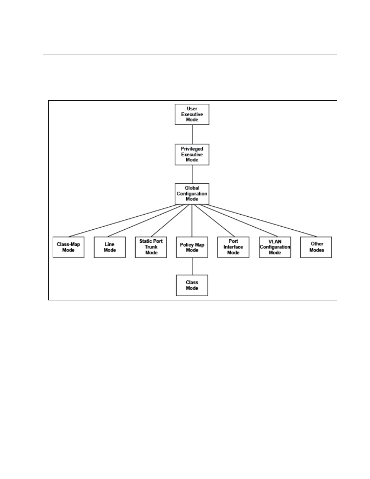
AlliedWare Plus™ Command Modes
The AlliedWare Plus™ command line interface consists of a series of
modes that are arranged in the hierarchy shown in Figure 1.
AT-DC2552SX Switch Command Line Interface User’s Guide
Figure 1. Command Modes
The modes have different commands and support different management
functions. To perform a management function, you first have to move to
the mode that has the appropriate commands. For instance, to add new
VLANs, you must move to the VLAN Configuration mode because the
VLAN command is effective only in that mode.
Section I: Switch Management 25
Page 26

Chapter 1: AlliedWare Plus™ Command Line Interface
awplus> enable
awplus#
awplus> enable
awplus# configure terminal
awplus(config)#
awplus(config)# class-map filecopy
awplus(config-cmap)#
Moving Down the Hierarchy
To move down the mode hierarchy, you must step through each mode in
sequence.
Each mode has a different command. For instance, to move from the User
Exec mode to the Privileged Exec mode, you use the ENABLE command.
Here are some examples.
ENABLE
Command
CONFIGURE
TERMINAL
Command
You use this command to move from the User Exec mode to the
Privileged Exec mode. The format of the command is:
enable
Figure 2. ENABLE Command
You use this command to move from the Privileged Exec mode to the
Global Configuration mode. The format of the command is:
configure terminal
Figure 3. CONFIGURE TERMINAL Command
CLASS-MAP
Command
26 Section I: Switch Management
You use this command to move from the Global Configuration mode to the
Class-Map mode in which you create classifiers and flow groups for
Quality of Service policies. The format of the command is:
class-map
class_name
Figure 4. CLASS-MAP Command
Page 27

AT-DC2552SX Switch Command Line Interface User’s Guide
awplus(config)# line console 0
awplus(config-line)#
LINE CONSOLE
0 Command
You use this command to move from the Global Configuration mode to the
Console Line mode to set the management session timer and to activate
or deactivate remote authentication for local management sessions. The
mode is also used to set the baud rate of the terminal port. The format of
the command is:
line console 0
Figure 5. LINE CONSOLE Command
Section I: Switch Management 27
Page 28
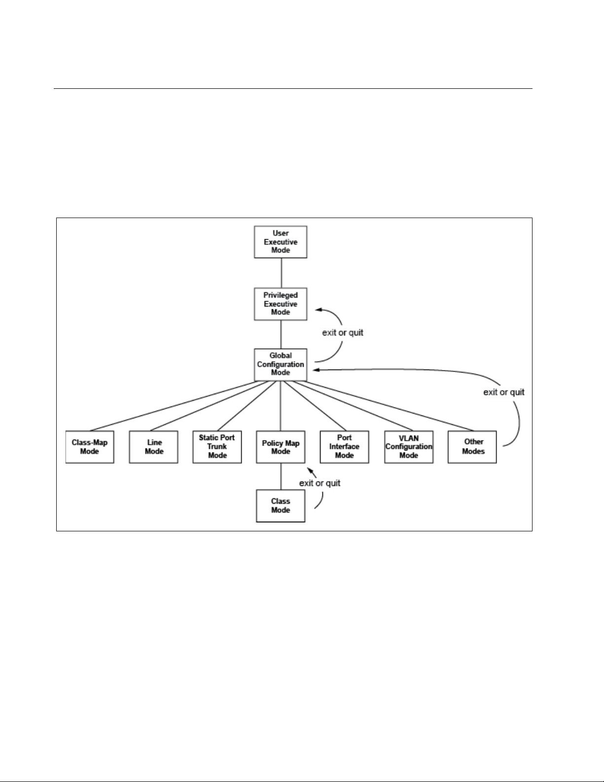
Chapter 1: AlliedWare Plus™ Command Line Interface
Moving Up the Hierarchy
Four commands are available for moving up the mode hierarchy. They are
the EXIT, QUIT, END and DISABLE commands.
EXIT and QUIT
Commands
These commands, which are functionally identical, are found in nearly all
of the modes. They move you up one level in the hierarchy, as illustrated
in Figure 6.
Figure 6. Moving Up One Mode with the EXIT and QUIT Command
END Command You may want to return to the User Exec mode or the Privileged Exec
mode after you have configured a feature. While you can step back
through the modes one at a time with the EXIT or QUIT command, the
END command moves you directly to the Privileged Exec mode from any
mode below the Global Configuration mode.
28 Section I: Switch Management
Page 29

AT-DC2552SX Switch Command Line Interface User’s Guide
DISABLE
Command
Figure 7. Returning to the Privileged Exec Mode with the END Command
To return to the User Exec mode from the Privileged Exec mode, use the
DISABLE command.
Figure 8. Returning to the User Exec Mode with the DISABLE Command
Section I: Switch Management 29
Page 30

Chapter 1: AlliedWare Plus™ Command Line Interface
Port ID Numbers in Commands
Here is the format for port ID numbers in commands:
port1.0.
n
The n variable is the number of the port you want to configure on the
switch. The two digits in the prefix “port1.0.” are used with modular
products and with products that support stacking. To specify a port
number on the DC2552XS switch, which is not a modular product and
does not support stacking, you must always use the prefix “port1.0.”
This example uses the INTERFACE PORT command to enter the Port
Interface mode for ports 1.0.12 and 1.0.18:
awplus> enable
awplus# configure terminal
awplus(config)# interface port1.0.12,port1.0.18
30 Section I: Switch Management
Page 31

Command Format
AT-DC2552SX Switch Command Line Interface User’s Guide
The following sections describe the command line interface features and
the command syntax conventions.
Command Line
Interface
Features
Command
Formatting
Conventions
Command
Examples
The command line interface has these features:
Command history - Use the up and down arrow keys.
Keyword abbreviations - Any keyword can be recognized by typing an
unambiguous prefix, for example, type “sh” and the software responds
with “show.”
Tab key - Pressing the Tab key fills in the rest of a keyword
automatically. For example, typing “sh” and then pressing the Tab key
enters “show” on the command line.
This manual uses the following command format conventions:
screen text font - This font illustrates the format of a command and
command examples.
[ ] - Brackets indicate optional parameters or keywords.
| - Vertical line separates parameter or keyword options for you to
choose from.
Italics - Italics indicate variables you provide.
Most of the command examples in this guide start at the User Exec mode
and include the navigational commands. Here is an example that creates
three new VLANs with VIDs 10, 20, and 30:
awplus> enable
awplus# configure terminal
awplus(config)# vlan database
awplus(config-vlan)# vlan 10,20,30
awplus(config-vlan)# exit
Section I: Switch Management 31
Page 32

Chapter 1: AlliedWare Plus™ Command Line Interface
32 Section I: Switch Management
Page 33

Chapter 2
Management Session Commands
The management session commands are summarized in Table 1.
Table 1. Management Session Commands
Command Mode Description
“BAUD-RATE SET” on page 36 Global
Configuration
“CLEAR LINE” on page 37 Privileged Exec Ends a remote management session
“CRYPTO KEY DESTROY
HOSTKEY” on page 38
“CRYPTO KEY GENERATE
HOSTKEY” on page 40
“EXEC-TIMEOUT” on page 42 Console Line and
“LENGTH” on page 44 Console Line and
“LINE CONSOLE 0” on page 46 Global
“LINE VTY” on page 47 Global
Global
Configuration
Global
Configuration
Virtual Terminal
Line
Virtual Terminal
Line
Configuration
Configuration
Sets the baud rate of the Console
port.
on another line.
Deletes an encryption key pair for the
SSH server.
Creates or updates an encryption key
pair for the SSH server.
Sets the management session timers.
Sets the maximum number of lines
that the SHOW commands display on
the screen for local and remote
management sessions.
Enters the Console Line mode.
Enters the Virtual Terminal Line mode.
“NO EXEC-TIMEOUT” on page 48 Console Line and
Virtual Terminal
Line
“NO LENGTH” on page 49 Console Line and
Virtual Terminal
Line
“NO SERVICE SSH” on page 50 Global
Configuration
Resets the management session
timers to 10 minutes.
Resets the maximum number of lines
the SHOW commands display on the
screen to 20 lines for local and remote
management sessions.
Disables the SSH server on the
switch.
33
Page 34

Chapter 2: Management Session Commands
Table 1. Management Session Commands (Continued)
Command Mode Description
“NO SERVICE PASSWORDENCRYPTION” on page 51
Global
Configuration
“NO SERVICE TELNET” on page 52 Global
Configuration
“NO SERVICE TERMINALLENGTH” on page 53
Global
Configuration
“NO USERNAME” on page 54 Global
Configuration
“SERVICE MAXMANAGER” on
page 55
“SERVICE PASSWORDENCRYPTION” on page 56
Global
Configuration
Global
Configuration
“SERVICE SSH” on page 57 Global
Configuration
Disables password encryption.
Disables the Telnet server on the
switch.
Resets the maximum number of lines
that the SHOW commands display on
the screen at once to the default value
of 20 lines.
Deletes manager accounts from the
switch.
Specifies the maximum number of
management accounts with a user
level of 15 that the switch allows to log
on to the switch at once.
Encrypts all manager account
passwords that are stored in the
running configuration file.
Enables the SSH server on the switch.
“SERVICE TELNET” on page 58 Global
Configuration
“SERVICE TERMINAL-LENGTH” on
page 59
Global
Configuration
Enables the Telnet server on the
switch.
Specifies the maximum number of
lines that the SHOW commands
display on the screen at once.
“SHOW BAUD-RATE” on page 60 User Exec Displays the settings of the Console
port.
“SHOW CRYPTO KEY HOSTKEY”
on page 62
Privileged Exec
and Global
Displays the encryption keys for the
SSH server.
Configuration
“SHOW SSH SERVER” on page 63 User Exec and
Privileged Exec
“SHOW TELNET” on page 64 User Exec and
Privileged Exec
Displays the status of the SSH server
on the switch.
Displays the status of the Telnet
server on the switch.
“SHOW USERS” on page 65 Privileged Exec Displays the managers who are
currently logged on the switch.
34 Section I: Switch Management
Page 35

AT-DC2552SX Switch Command Line Interface User’s Guide
Table 1. Management Session Commands (Continued)
Command Mode Description
“TERMINAL LENGTH” on page 67 User Exec Specifies the maximum number of
lines that the SHOW commands
display on the screen in your current
session.
“TERMINAL NO LENGTH” on
page 68
User Exec Resets the maximum number of lines
that the SHOW commands display on
the screen to 20 lines in your current
session.
“TELNET” on page 69 Privileged Exec Starts Telnet management sessions
on network devices.
“USERNAME” on page 70 Global
Creates new manager accounts.
Configuration
Section I: Switch Management 35
Page 36

Chapter 2: Management Session Commands
BAUD-RATE SET
Syntax
baud-rate set
baud_rate
Parameter
baud_rate
Specifies the baud rate of the Console port in bps. The options are
1200, 2400, 4800, 9600, 19200, 38400, 57600, and 115200.
Mode
Global Configuration mode
Description
Use this command to set the baud rate of the Console port, which is used
for local management sessions of the switch. After changing the baud rate
of the Console port, change the baud rate of the Console terminal. These
two baud rates must be the same.
Confirmation Command
“SHOW BAUD-RATE” on page 60
Example
This example sets the baud rate of the Console port to 9600 bps:
awplus> enable
awplus# configure terminal
awplus(config)# baud-rate set 9600
Baud rate changed to 9600 bps.
Change your console baud correspondingly.
awplus(config)#
36 Section I: Switch Management
Page 37

CLEAR LINE
AT-DC2552SX Switch Command Line Interface User’s Guide
Syntax
clear line
line_number
Parameter
line_number
Specifies the line number of a remote Telnet or SSH management
session. The line number ranges from 0 to 9.
Mode
Privileged Exec mode
Description
Use this command to log out of a specific remote Telnet or SSH
management session on another line. To view the line numbers, see the
Line Field in the SHOW USERS commands. The value of the line_number
parameter is the value of N in “vtyN.” See “SHOW USERS” on page 65.
Confirmation Command
“SHOW USERS” on page 65
Example
This example ends a remote management session on vty 0:
awplus> clear line 0
Section I: Switch Management 37
Page 38

Chapter 2: Management Session Commands
CRYPTO KEY DESTROY HOSTKEY
Syntax
crypto key destroy hostkey dsa|rsa|rsa1
Parameters
dsa
Deletes the DSA host key in SSH protocol version 2.
rsa
Deletes the RSA host key in SSH protocol version 2.
rsa1
Deletes the RSA1 host key in SSH protocol version 1.
Mode
Global Configuration mode
Confirmation Command
“SHOW CRYPTO KEY HOSTKEY” on page 62
Description
Use this command to delete an encryption key pair for the SSH server.
The encryption keys are stored in files in Flash memory on the switch.
This command deletes the files directly from the Flash memory so that you
do not have to enter the WRITE command or the COPY RUNNINGCONFIG STARTUP-CONFIG command to save your changes.
See Table 2 for the file names associated with the encryption keys.
Table 2. SHOW BAUD-RATE Command
Keyword FIle Names
dsa ssh_host_dsa_key, ssh_host_dsa_key.pub
rsa ssh_host_rsa_key, ssh_host_rsa_key.pub
rsa1 ssh_host_key, ssh_host_key.pub
38 Section I: Switch Management
Page 39

AT-DC2552SX Switch Command Line Interface User’s Guide
Example
This example deletes the DSA key:
awplus> enable
awplus# configure terminal
awplus(config)# crypto key destroy hostkey dsa
Section I: Switch Management 39
Page 40

Chapter 2: Management Session Commands
CRYPTO KEY GENERATE HOSTKEY
Syntax
crypto key generate hostkey dsa|rsa|rsa1 [
Parameters
dsa
Creates a DSA key pair in SSH protocol version 2.
rsa
Creates an RSA key pair in SSH protocol version 2.
rsa1
Creates an RSA1 key pair in SSH protocol version 1.
key_length
Specifies the length of the encryption key, in bits, for the RSA key.
This parameter is valid only when you specify the RSA key. The
range is 768 to 2,048 bits. If you do not specify this parameter for
the RSA key, the key length of the RSA key is 1024 bits. The DSA
and RSA1 keys have fixed lengths of 1024 bits.
Mode
Global Configuration mode
key_length
]
Confirmation Command
“SHOW CRYPTO KEY HOSTKEY” on page 62
Description
Use this command to create or update an encryption key pair for the SSH
server. You must create at least one encryption key pair before enabling
the sever. The switch can have one key pair of each type, DSA, RSA, and
RSA1, at the same time.
If you create a new key when the switch already has a key of that type, the
new key overwrites the old key. For example, if you create a new RSA key
when the switch already has an RSA key, the new key replaces the
existing key.
When the switch does not have an RSA1 key pair for SSH protocol
version 1, you cannot connect to the switch in SSH protocol version 1.
Similarly, when the switch does not have either a DSA or RSA key pair for
SSH protocol version 2, you cannot connect to the switch in SSH protocol
version 2.
40 Section I: Switch Management
Page 41

AT-DC2552SX Switch Command Line Interface User’s Guide
A new encryption key is saved in the Flash memory of the switch when
you enter the command. After entering this command, you do not have to
enter WRITE command or the COPY RUNNING-CONFIG STARTUPCONFIG command to save your changes on the switch.
Examples
This example creates a DSA key:
awplus> enable
awplus# configure terminal
awplus(config)# crypto key generate hostkey dsa
This example creates an RSA key with a length of 1280 bits:
awplus> enable
awplus# configure terminal
awplus(config)# crypto key generate hostkey rsa 1280
Section I: Switch Management 41
Page 42

Chapter 2: Management Session Commands
EXEC-TIMEOUT
Syntax
exec-timeout
value
Parameter
value
Specifies the session timer in minutes. The range is 0 to 35,791
minutes. Assign a value of 0 if you do not want to time out a
session. The default value is 10 minutes.
Modes
Console Line and Virtual Terminal Line modes
Description
Use this command to set the management session timers. The timers are
used by the switch to end inactive management sessions. The switch
deems a management session inactive when a management session has
no activity for the duration of a timer.
Local management sessions, which are conducted through the Console
port on the switch, and remote Telnet and SSH sessions have different
timers. To set the timer for local management sessions, enter the
command in the Line Console mode. To set the timers for remote Telnet
and SSH sessions, enter the command in the Virtual Terminal Line mode.
Confirmation Command
“SHOW SWITCH” on page 117
Examples
This example sets the session timer for local management sessions to 0
minutes which indicates to not time out sessions:
awplus> enable
awplus# configure terminal
awplus(config)# line console 0
awplus(config-line)# exec-timeout 0
42 Section I: Switch Management
Page 43

AT-DC2552SX Switch Command Line Interface User’s Guide
This example sets the timer for remote management sessions to 3
minutes:
awplus> enable
awplus# configure terminal
awplus(config)# line vty 0 9
awplus(config-line)# exec-timeout 3
Section I: Switch Management 43
Page 44

Chapter 2: Management Session Commands
LENGTH
Syntax
length
length
Parameter
length
Specifies the maximum number of lines that the SHOW commands
display on the screen at once. The range is 0 to 512 lines. Assign a
value of 0 if you do not want the SHOW commands to pause. The
default value is 20 lines.
Mode
Console Line and Virtual Terminal Line modes
Description
Use this command to specify the maximum number of lines that the
SHOW commands display on the screen at once. You can set different
values for the local and remote management sessions with this command.
For local management sessions, enter the command in the Console
line mode.
For remote Telnet and SSH sessions, enter the command in the Virtual
Terminal Line (VTY) mode.
If the maximum numbers of lines are set by the TERMINAL LENGTH or
SERVICE TERMINAL-LENGTH command, the switch uses these settings
to display output. Here is the priority of the commands, listing the highest
priority command first:
1. The TERMINAL LENGTH command
2. The SERVICE TERMINAL-LENGTH command
3. The LENGTH command
Confirmation Command
“SHOW RUNNING-CONFIG” on page 116
44 Section I: Switch Management
Page 45

AT-DC2552SX Switch Command Line Interface User’s Guide
Examples
This example sets the maximum number of lines to 25 for local
management sessions:
awplus> enable
awplus# configure terminal
awplus(config)# line console 0
awplus(config-line)# length 25
This example sets the maximum number of lines to 15 for the Telnet and
SSH sessions:
awplus> enable
awplus# configure terminal
awplus(config)# line vty 0 9
awplus(config-line)# length 15
Section I: Switch Management 45
Page 46

Chapter 2: Management Session Commands
LINE CONSOLE 0
Syntax
line console 0
Parameters
None
Mode
Global Configuration mode
Description
Use this command to enter the Console Line mode.
Example
This example enters the Console Line mode:
awplus> enable
awplus# configure terminal
awplus(config)# line console 0
awplus(config-line)#
46 Section I: Switch Management
Page 47

LINE VTY
AT-DC2552SX Switch Command Line Interface User’s Guide
Syntax
line vty
line_id [ending_line_id
]
Parameters
line_id
Specifies the number of a VTY line. The range is 0 to 9.
ending_line_id
Specifies the last number of a VTY line that you want to configure.
The range is 0 to 9.
Mode
Global Configuration mode
Description
Use this command to enter the Virtual Terminal Line mode for a VTY line.
Commands that are entered in the VTY Line mode apply to a group of the
VTY lines with the range beginning with line_id value and ending with
ending_line_id value.
Examples
This example enters the Virtual Terminal Line mode for VTY line 0:
awplus> enable
awplus# configure terminal
awplus(config)# line vty 0
awplus(config-line)#
This example enters the Virtual Terminal Line mode for multiple VTY lines,
from VTY 0 to VTY 9:
awplus> enable
awplus# configure terminal
awplus(config)# line vty 0 9
awplus(config-line)#
Section I: Switch Management 47
Page 48

Chapter 2: Management Session Commands
NO EXEC-TIMEOUT
Syntax
no exec-timeout
Parameters
None
Modes
Console Line and Virtual Terminal Line modes
Description
Use this command to reset the management session timers to 10 minutes.
Confirmation Command
“SHOW SWITCH” on page 117
Example
This example sets the session timer for local management sessions to 10
minutes:
awplus> enable
awplus# configure terminal
awplus(config)# line console 0
awplus(config-line)# no exec-timeout
48 Section I: Switch Management
Page 49

NO LENGTH
AT-DC2552SX Switch Command Line Interface User’s Guide
Syntax
no length
Parameters
None
Mode
Console Line and Virtual Terminal Line modes
Description
Use this command to reset the maximum number of lines that the SHOW
commands display at once to the default value of 20 lines. You can apply
this setting to local and remote management sessions.
Confirmation Command
“SHOW SWITCH” on page 117
Examples
This example resets the maximum number of lines to display to the default
value, 20 lines, for local management sessions:
awplus> enable
awplus# configure terminal
awplus(config)# line console 0
awplus(config-line)# no length
This example resets the maximum number of lines to display to the default
value, 20 lines, for remote management sessions:
awplus> enable
awplus# configure terminal
awplus(config)# line vty 0 9
awplus(config-line)# no length
Section I: Switch Management 49
Page 50

Chapter 2: Management Session Commands
NO SERVICE SSH
Syntax
no service ssh
Parameters
None
Mode
Global Configuration mode
Description
Use this command to disable the SSH server on the switch. By default, the
SSH server is disabled.
Confirmation Command
“SHOW SSH SERVER” on page 63
Example
This example disables the SSH server:
awplus(config)# no service ssh
50 Section I: Switch Management
Page 51

AT-DC2552SX Switch Command Line Interface User’s Guide
NO SERVICE PASSWORD-ENCRYPTION
Syntax
no service password-encryption
Parameters
None.
Mode
Global Configuration mode
Description
Use this command to disable password encryption. Passwords originally
defined in plain text are displayed in plain text in the running-config file.
However, encrypted passwords stay encrypted in the running-config file
even after this command is issued. Passwords originally entered in plain
text and then encrypted and saved in the startup-config file remain
encrypted.
Confirmation Command
“SHOW RUNNING-CONFIG” on page 116
Example
The following example disables password encryption:
awplus> enable
awplus# configure terminal
awplus(config)# no service password-encryption
Section I: Switch Management 51
Page 52

Chapter 2: Management Session Commands
NO SERVICE TELNET
Syntax
service telnet
Parameters
None
Mode
Global Configuration mode
Description
Use this command to disable the Telnet server on the switch. By default,
the Telnet server is enabled.
Confirmation Command
“SHOW TELNET” on page 64
Example
This example disables the Telnet server:
awplus(config)# no service telnet
52 Section I: Switch Management
Page 53

NO SERVICE TERMINAL-LENGTH
Syntax
no service terminal-length
Parameters
None
Mode
Global Configuration mode
Description
Use this command to reset the maximum number of lines that the SHOW
commands display on the screen at once to the default value of 20 lines.
AT-DC2552SX Switch Command Line Interface User’s Guide
Example
This example resets the maximum number of lines to the default value of
20 lines:
awplus> enable
awplus# configure terminal
awplus(config)# no service terminal-length
Section I: Switch Management 53
Page 54

Chapter 2: Management Session Commands
NO USERNAME
Syntax
no username
name
Parameter
name
Specifies the name of the manager account. The name is casesensitive.
Mode
Global Configuration mode
Description
Use this command to delete local manager accounts from the switch. You
can delete the default “manager” account from the switch as well.
Confirmation Command
“SHOW RUNNING-CONFIG” on page 116
Example
This example deletes the manager account “msmith”:
awplus> enable
awplus# configure terminal
awplus(config)# no username msmith
54 Section I: Switch Management
Page 55

SERVICE MAXMANAGER
Syntax
AT-DC2552SX Switch Command Line Interface User’s Guide
service maxmanager
value
Parameter
value
Specifies the maximum number of management accounts with a
user level of 15 that the switch allows to be open at once. The
range is 1 to 3. The default is 3.
Mode
Global Configuration mode
Description
Use this command to set the maximum number of management accounts
with a user level of 15 that the switch allows to log on to the switch
simultaneously. Management accounts with a user level of 15 have
unrestricted access to the management software.
Confirmation Command
“SHOW RUNNING-CONFIG” on page 116
Example
This example permits only one management account, with a user level of
15, to log on to the switch at one time:
awplus(config)# service maxmanager 1
Section I: Switch Management 55
Page 56

Chapter 2: Management Session Commands
SERVICE PASSWORD-ENCRYPTION
Syntax
service password-encryption
Parameters
None
Mode
Global Configuration mode
Description
Use this command to encrypt all manager account passwords and the
value assigned to the ENABLE PASSWORD in all configuration files on
the switch. By default, passwords are stored in encrypted form in
configuration files. For more information about the ENABLE PASSWORD
command, see “ENABLE PASSWORD” on page 80.
Confirmation Command
“SHOW RUNNING-CONFIG” on page 116
Example
This example encrypts all manager account passwords and the value of
the ENABLE PASSWORD command in all configuration files on the
switch:
awplus> enable
awplus# configure terminal
awplus(config)# service password-encryption
56 Section I: Switch Management
Page 57

SERVICE SSH
AT-DC2552SX Switch Command Line Interface User’s Guide
Syntax
service ssh
Parameters
None
Mode
Global Configuration mode
Description
Use this command to enable the SSH server on the switch so that you can
manage the switch remotely with the SSH protocol. By default, the SSH
server is disabled.
Before enabling the SSH server, you must create at least one encryption
key for the SSH server using the “CRYPTO KEY GENERATE HOSTKEY”
on page 40.
Confirmation Command
“SHOW SSH SERVER” on page 63
Example
This example enables the SSH server:
awplus(config)# service ssh
Section I: Switch Management 57
Page 58

Chapter 2: Management Session Commands
SERVICE TELNET
Syntax
service telnet
Parameters
None
Mode
Global Configuration mode
Description
Use this command to enable the Telnet server on the switch so that you
can manage the switch remotely with the Telnet protocol. By default, the
Telnet server is enabled.
Confirmation Command
“SHOW TELNET” on page 64
Example
This example enables Telnet server:
awplus(config)# service telnet
58 Section I: Switch Management
Page 59

SERVICE TERMINAL-LENGTH
Syntax
AT-DC2552SX Switch Command Line Interface User’s Guide
service maxmanager
length
Parameter
length
Specifies the maximum number of lines that the SHOW commands
display on the screen at once. The range is 0 to 512 lines. Use the
value 0 if you do not want the SHOW commands to pause. The
default value is 20 lines.
Mode
Global Configuration mode
Description
Use this command to specify the maximum number of lines that the
SHOW commands display on the screen at once.
If the maximum number of lines is set by the TERMINAL LENGTH
command, the switch uses that setting to displays output. Here is the
priority of the commands, listing the highest priority command first:
1. The TERMINAL LENGTH command
2. The SERVICE TERMINAL-LENGTH command
3. The LENGTH command
Confirmation Command
“SHOW RUNNING-CONFIG” on page 116
Example
This example sets the maximum number of lines to 30:
awplus> enable
awplus# configure terminal
awplus(config)# service terminal-length 30
Section I: Switch Management 59
Page 60

Chapter 2: Management Session Commands
Note
Asynchronous Port (Console) Information:
Baud Rate .................... 115200
Parity ....................... None
Data bits .................... 8
Stop bits .................... 1
SHOW BAUD-RATE
Syntax
show baud-rate
Parameters
None
Mode
User Exec mode
Description
Use this command to display the Console port settings, which are used for
local management sessions on the switch. See Figure 9 for an example of
the command output.
Figure 9. SHOW BAUD-RATE Command
The fields are described in Table 3.
Table 3. SHOW BAUD-RATE Command
Field Description
Baud Rate Displays the speed of the data transmission in bps on
the Console port.
Parity Displays the type of parity checking. It is always is set to
“None.”
Data bits Displays the length of data bits. It is always set to “8.”
Stop bits Displays the length of stop bits. It is always set to “1.”
The Baud Rate is the only adjustable parameter on the Console
port.
60 Section I: Switch Management
Page 61

AT-DC2552SX Switch Command Line Interface User’s Guide
Example
This example displays the Console port settings:
awplus# show baud-rate
Section I: Switch Management 61
Page 62

Chapter 2: Management Session Commands
Type Bits Fingerprint
-----------------------------------------------------
RSA1 1024 62:72:40:cd:e6:61:55:c0:47:2b:0d:3b:69:a1:0a:06
RSA 1024 8a:50:a5:a0:c8:7b:7d:2f:ab:b2:80:8a:b2:d0:1f:bb
DSA 1024 a3:9c:c6:97:28:ce:89:e7:30:a7:07:d2:bf:53:b0:d0
SHOW CRYPTO KEY HOSTKEY
Syntax
show crypto key hostkey [dsa|rsa|rsa1]
Parameters
dsa
Displays the DSA key pair.
rsa
Displays the RSA key pair.
rsa1
Displays the RSA1 key pair.
Modes
Privileged Exec and Global Configuration modes
Description
Use this command to display the encryption keys. See Figure 10 for an
example of the command output.
Figure 10. SHOW CRYPTO KEY HOSTKEY Command
Examples
This example displays the encryption keys:
awplus# show crypto key hostkey
This example displays the RSA1 key only:
62 Section I: Switch Management
awplus# show crypto key hostkey rsa1
Page 63

SHOW SSH SERVER
Secure Shell Server Configuration
Versions Supported .......... 2,1
SSH Server: Enabled
Server Port ................. 22
Syntax
show ssh server
Parameters
None
Modes
User Exec mode and Privileged Exec mode
Description
Use this command to display the status of the SSH server on the switch.
The status of the SSH server can be either enabled or disabled. See
Figure 11 for an example of the command output.
AT-DC2552SX Switch Command Line Interface User’s Guide
Figure 11. SHOW SSH SERVER Command
The fields are described in Table 4.
Table 4. SHOW BAUD-RATE Command
Field Description
Versions Supported Displays the enabled SSH versions.
SSH Server Displays whether the SSH server is enabled
or disabled.
Server Port Displays the TCP port number of the SSH
server.
Example
This example displays the status of the SSH server on the switch:
awplus# show ssh server
Section I: Switch Management 63
Page 64

Chapter 2: Management Session Commands
Telnet Server Configuration
------------------------------------------------------Telnet Server: Enabled
SHOW TELNET
Syntax
show telnet
Parameters
None
Modes
User Exec mode and Privileged Exec mode
Description
Use this command to display the status of the Telnet server on the switch.
The status of the Telnet server can be either enabled or disabled. See
Figure 12 for an example of the command output.
Figure 12. SHOW TELNET Command
Example
This example displays the status of the Telnet server on the switch:
awplus# show telnet
64 Section I: Switch Management
Page 65

SHOW USERS
Line User Host(s) Idle Location
con0 manager idle 00:00:00 ttyS0
vty0 manager idle 00:01:25 172.17.28.70
vty1 manager idle 00:04:06 172.17.28.71
AT-DC2552SX Switch Command Line Interface User’s Guide
Syntax
show users
Parameters
None
Mode
Privileged Exec mode
Description
Use this command to display the managers who are currently logged onto
the switch. See Figure 13 for an example of the output.
Figure 13. SHOW USERS Command
The columns are described in Table 5.
Table 5. SHOW USERS Command
Field Description
Line Indicates an active management session. The possible
designators are:
con0: a local management session.
vtyN: a remote Telnet and SSH session where N is a
number that is assigned to the session.
User Indicates the user name that is logged into the account.
Host(s) Not supported.
Idle Indicates the idling time.
Location Indicates the network device from which the manager is
accessing the switch. A device connected to the Console
port is identified by “ttyS0” while remote Telnet and SSH
devices are identified by their IP addresses.
Section I: Switch Management 65
Page 66

Chapter 2: Management Session Commands
Example
This example displays the managers who are logged on to the switch:
awplus# show users
66 Section I: Switch Management
Page 67

TERMINAL LENGTH
Syntax
AT-DC2552SX Switch Command Line Interface User’s Guide
terminal length
length
Parameter
length
Specifies the maximum number of lines that the SHOW commands
display on the screen at once. The range is 0 to 512 lines. Assign a
value of 0 if you do not want the SHOW commands to pause. The
default value is 20 lines.
Mode
User Exec mode
Description
Use this command to specify the maximum number of lines that the
SHOW commands display on the screen at once in your current session.
The setting of this command is effective only for your current session and
is not stored in the running configuration. This command overrides the
settings by the SERVICE TERMINAL-LENGTH and LENGTH commands.
Confirmation Command
None
Example
This example sets the maximum number of lines to 30 for your current
session:
awplus> enable
awplus# terminal length 30
Section I: Switch Management 67
Page 68

Chapter 2: Management Session Commands
TERMINAL NO LENGTH
Syntax
terminal no length
Parameters
None
Mode
Privileged Exec mode
Description
Use this command to reset the maximum number of lines that the SHOW
commands display on the screen at once to the default value of 20 lines in
your current session.
Confirmation Command
None
Example
This example resets the maximum number of lines to the default value of
20 lines:
awplus(config)# terminal no length
68 Section I: Switch Management
Page 69

TELNET
AT-DC2552SX Switch Command Line Interface User’s Guide
Syntax
telnet
ipv4_address
Parameter
ipv4_address
Specifies the IPv4 address of a remote device you want to manage
using the Telnet client on the switch.
Mode
Privileged Exec mode
Description
Use this command to start a Telnet management session on a network
device that has an IPv4 address. You can manage one remote device at a
time.
Example
This example starts a Telnet management session on a network device
that has an IP address of 10.0.0.10:
awplus> enable
awplus# telnet 10.0.0.10
Section I: Switch Management 69
Page 70

Chapter 2: Management Session Commands
USERNAME
Syntax
username
Parameters
name
Specifies the name of a new manager account or existing manager
account. The name is case-sensitive and can be up to 15
alphanumeric characters. Spaces and special characters are not
permitted.
privilege
Specifies this keyword to assign the privilege level of either 1 or 15,
or modify the privilege level. If you do not specify the privilege level
when creating a new account, the privilege level of the new
account is set to 1 automatically. If you do not specify the privilege
level when modifying an existing account, the existing account’s
privilege level remains the same.
1
Specifies a manager account with the privilege level of 1. A
manager account with the privilege level of 1 is restricted to the
User Exec mode when command mode restriction is activated with
the ENABLE PASSWORD command. However, a manager
account with the privilege level of 1 can move to the Privileged
Exec mode if the user enters the correct password.
name
[privilege 1|15] password [8]
password
15
Specifies a manager account with the privilege level of 15. A
manager account with the privilege level of 15 has access to all
modes.
password
Assigns a new password or modifies an existing password. You
must set the password when creating a new account. The
password setting is optional when you modify an existing account.
If you do not specify a password when modifying an existing
account, the existing account’s password stays the same.
8
Specifies that the password is encrypted.
70 Section I: Switch Management
Page 71

AT-DC2552SX Switch Command Line Interface User’s Guide
password
Specifies the password of the new manager account. A password
is case-sensitive and can be up to 16 alphanumeric characters.
Special characters are permitted with the exception of spaces,
exclamation points (!), and question marks (?).
Mode
Global Configuration mode
Description
Use this command to create a new manager account or modify the
password and privilege levels of an existing manager account.
Confirmation Command
“SHOW RUNNING-CONFIG” on page 116
Examples
This example creates a manager account with the user name “allen.” The
privilege level is 15 provides the manager access to all modes even when
command mode restriction is activated. The password is “laf238pl”:
awplus> enable
awplus# configure terminal
awplus(config)# username allen privilege 15 password
laf238pl
This example creates a manager account for the user “sjones.” The
privilege level is 1 to restrict the manager to the User Exec mode. The
password is “bluesky,” entered in its encrypted form.
awplus> enable
awplus# configure terminal
awplus(config)# username sjones privilege 1 password 8
c1a23116461d5856f98ee072ea319bc9
Section I: Switch Management 71
Page 72

Chapter 2: Management Session Commands
72 Section I: Switch Management
Page 73

Chapter 3
Basic Command Line Management Commands
The basic command line commands are summarized in Table 6.
Table 6. Basic Command Line Commands
Command Mode Description
“CLEAR SCREEN” on page 75 User Exec and
Privileged Exec
“CONFIGURE TERMINAL” on
page 76
“DISABLE” on page 77 Privileged Exec Returns you to the User Exec mode
“DO” on page 78 Global
“ENABLE” on page 79 User Exec Moves you from the User Exec mode
“ENABLE PASSWORD” on page 80 Global
“END” on page 81 All modes below
Privileged Exec Moves you from the Privileged Exec
Configuration
Configuration
the Global
Configuration
mode
Clears the screen.
mode to the Global Configuration
mode.
from the Privileged Exec mode.
Performs Privileged Exec mode
commands from the Global
Configuration mode.
to the Privileged Exec mode.
Specifies the password which permits
management accounts with a privilege
level of 1 an option to move to the
Privilege Exec mode.
Returns you to the Privileged Exec
mode.
“EXIT” on page 82 All modes except
the User Exec
and Privileged
Exec
“LOGOUT” on page 83 User Exec Ends a management session.
“NO ENABLE PASSWORD” on
page 84
Global
Configuration
Moves you up one mode.
Removes the password which permits
management accounts with a privilege
level of 1 to move to the Privilege
Exec mode.
73
Page 74

Chapter 3: Basic Command Line Management Commands
Table 6. Basic Command Line Commands (Continued)
Command Mode Description
“QUIT” on page 85 All modes except
the User Exec
and Privileged
Exec
Moves you up one mode.
74 Section I: Switch Management
Page 75

CLEAR SCREEN
AT-DC2552SX Switch Command Line Interface User’s Guide
Syntax
clear screen
Parameters
None
Modes
User Exec mode
Description
Use this command to clear the screen.
Example
This example clears the screen:
awplus> clear screen
Section I: Switch Management 75
Page 76

Chapter 3: Basic Command Line Management Commands
CONFIGURE TERMINAL
Syntax
configure terminal
Parameters
None
Mode
Privileged Exec mode
Description
Use this command to move from the Privileged Exec mode to the Global
Configuration mode.
Example
This example moves you from the Privileged Exec mode to the Global
Configuration mode:
awplus# configure terminal
awplus(config)#
76 Section I: Switch Management
Page 77

DISABLE
AT-DC2552SX Switch Command Line Interface User’s Guide
Syntax
disable
Parameters
None
Mode
Privileged Exec mode
Description
Use this command to return to the User Exec mode from the Privileged
Exec mode.
To move from the User Exec mode to the Privileged Exec mode, see
“ENABLE” on page 79.
Example
The following command returns the software to the User Exec mode:
awplus# disable
awplus>
Section I: Switch Management 77
Page 78

Chapter 3: Basic Command Line Management Commands
DO
Syntax
do
command
Parameter
command
Specifies the command to perform in the Privileged Exec mode.
Mode
Global Configuration mode and modes below the Global Configuration
mode
Description
Use this command to perform Privileged Exec mode commands from the
Global Configuration mode, or modes below the Global Configuration
mode, such as, the Line, Port Interface, VLAN Configuration modes. You
may use the command to perform some, but not all, of the Privileged Exec
mode commands.
Examples
This example performs the SHOW INTERFACE command for port 1.0.4
from the Global Configuration mode:
awplus(config)# do show interface port1.0.4
This example pings a network device:
awplus(config)# do ping 149.11.123.45
78 Section I: Switch Management
Page 79

ENABLE
AT-DC2552SX Switch Command Line Interface User’s Guide
Syntax
enable
Parameters
None
Mode
User Exec mode
Description
Use this command to move from the User Exec mode to the Privileged
Exec mode. To return to the User Exec mode, see “DISABLE” on page 77.
Example
This example moves management accounts with a privilege level of 15
from the User Exec mode to the Privileged Exec mode:
awplus> enable
awplus#
Section I: Switch Management 79
Page 80

Chapter 3: Basic Command Line Management Commands
Note
ENABLE PASSWORD
Syntax
enable password [8]
password
Parameters
8
Specifies that the password is encrypted.
password
Specifies a password. A plaintext password is case-sensitive and
can have up to 16 alphanumeric characters including special
characters. Spaces are not permitted.
Mode
Global Configuration mode
Description
Use this command to specify a password to enable management accounts
with a privilege level of 1 to move to the Privilege Exec mode from the
User Exec mode. By default, the password is not specified and
management accounts with a privilege level of 1 are restricted to the User
Exec mode.
For management accounts with privilege level 1 to move to the Privilege
Exec mode from the User Exec mode, you must set a password with this
command. Then you must enter this password with the ENABLE
command.
Management accounts with a privilege level of 15 are permitted to
move to the Privilege Exec mode without entering a password.
Confirmation Command
show running-config
Example
This example specifies the password as “x8pgHUdh”:
awplus> enable
awplus# configure terminal
awplus# enable password x8pgHUdh
80 Section I: Switch Management
Page 81

END
AT-DC2552SX Switch Command Line Interface User’s Guide
Syntax
end
Parameters
None
Mode
All modes below the Global Configuration mode.
Description
Use this command to return to the Privileged Exec mode.
The shortcut key of the END command is Ctrl-Z.
Example
The following command returns the prompt to the Privileged Exec mode:
awplus(config-if)# end
awplus#
Section I: Switch Management 81
Page 82

Chapter 3: Basic Command Line Management Commands
EXIT
Syntax
exit
Parameters
None
Mode
All modes
Description
Use this command to move up one mode in the mode hierarchy in all
modes except the User Exec and Privileged Exec modes. Using the EXIT
command in the User Exec and Privileged Exec modes terminates the
management session.
The shortcut key of the EXIT command is Ctrl-D.
Example
The following example moves the prompt from the Global Configuration
mode to the Privileged Exec mode:
awplus(config)# exit
awplus#
82 Section I: Switch Management
Page 83

LOGOUT
Note
AT-DC2552SX Switch Command Line Interface User’s Guide
Syntax
logout
Parameters
None
Mode
User Exec and Privileged Exec modes
Description
Use this command to end a management session.
Entering the EXIT command in either the User Exec or Privileged
Exec mode also ends a management session. See “EXIT” on
page 82.
Example
This example shows the sequence of commands to logout, starting from
the Global Configuration mode:
awplus(config)# exit
awplus# disable
awplus> logout
Section I: Switch Management 83
Page 84

Chapter 3: Basic Command Line Management Commands
Note
NO ENABLE PASSWORD
Syntax
no enable password
Parameters
None
Mode
Global Configuration mode
Description
Use this command to remove the password that permits management
accounts with a privilege level of 1 to move to the Privilege Exec mode
from the User Exec mode.
Management accounts with a privilege level of 15 are permitted to
move to the Privilege Exec mode without entering a password and
are not affected by this command.
Confirmation Command
show running-config
Example
This example removes the password to permit management accounts with
a privilege level of 1 to move to the Privilege Exec mode:
awplus> enable
awplus# configure terminal
awplus# no enable password
84 Section I: Switch Management
Page 85

QUIT
AT-DC2552SX Switch Command Line Interface User’s Guide
Syntax
quit
Parameters
None
Mode
All modes except the User Exec and Privileged Exec modes
Description
Use this command to move up one mode in the mode hierarchy. This
command is similar to the EXIT command. The difference is that unlike the
EXIT command, the QUIT command cannot be used to end a
management session.
The shortcut key of the QUIT command is Ctrl-D.
Example
This example moves you from the Global Configuration mode to the
Privileged Exec mode:
awplus(config)# quit
awplus#
Section I: Switch Management 85
Page 86

Chapter 3: Basic Command Line Management Commands
86 Section I: Switch Management
Page 87

Chapter 4
Basic Switch Operations Commands
The basic switch operations commands are summarized in Table 7.
Table 7. Basic Switch Operations Commands
Command Mode Description
“BANNER EXEC” on page 89 Global
Configuration
“BANNER LOGIN” on page 90 Global
Configuration
“BANNER MOTD” on page 91 Global
Configuration
“BOOT SYSTEM” on page 92 Global
Configuration
“CLOCK SET” on page 93 Privileged Exec Manually sets the date and time.
“ERASE STARTUP-CONFIG” on
page 95
“HOSTNAME” on page 96 Global
“NO BANNER EXEC” on page 97 Global
“NO BANNER LOGIN” on page 98 Global
Privileged Exec Deletes the boot configuration file to
Configuration
Configuration
Configuration
Creates a User Exec and Privileged
Exec modes banner.
Creates a login banner.
Creates a message-of-the-day
banner.
Specifies a management software
image file that the switch uses when
the system is rebooted or reloaded.
restore the default settings.
Assigns a name to the switch.
Deletes the banner message.
Deletes the banner login message.
“NO BANNER MOTD” on page 99 Global
Configuration
“NO HOSTNAME” on page 100 Global
Configuration
“REBOOT” on page 101 Privileged Exec Resets the switch.
“RELOAD” on page 102 Privileged Exec Resets the switch.
“SHOW BOOT” on page 103 Privileged Exec Displays information about the
Deletes the banner message-of-theday.
Deletes the switch’s name without
assigning a new name.
management software and
configuration file.
87
Page 88

Chapter 4: Basic Switch Operations Commands
Table 7. Basic Switch Operations Commands (Continued)
Command Mode Description
“SHOW CLOCK” on page 105 User Exec and
Displays the date and time.
Privileged Exec
“SHOW CPU” on page 106 Privileged Exec Displays a list of running processes
with their CPU utilization.
“SHOW CPU HISTORY” on page 109 Privileged Exec Displays graphs of historical CPU
utilization.
“SHOW MEMORY” on page 110 Privileged Exec Displays the memory consumption of
each process.
“SHOW MEMORY HISTORY” on
page 112
Privileged Exec Displays graphs of historical memory
utilization.
“SHOW PROCESS” on page 113 Privileged Exec Displays a list of running processes
with their CPU utilization.
“SHOW RUNNING-CONFIG” on
Privileged Exec Displays the settings of the switch.
page 116
“SHOW SWITCH” on page 117 Privileged Exec Displays general information about
the switch.
“SHOW SYSTEM” on page 119 Privileged Exec Displays general information about
the switch.
“SHOW SYSTEM ENVIRONMENT”
on page 122
“SHOW SYSTEM PLUGGABLE” on
page 124
“SHOW SYSTEM PLUGGABLE
DETAIL” on page 126
“SHOW SYSTEM SERIALNUMBER”
on page 128
“SHOW TECH-SUPPORT” on
Privileged Exec Displays detailed information about
the switch, PSUs, and fan modules.
Privileged Exec Displays information about the SFP+
and QSFP+ modules.
Privileged Exec Displays detailed information about
the SFP+ QSFP+ modules.
Privileged Exec Displays the serial number of the
switch.
Privileged Exec Generates a debug log file.
page 129
“SHOW VERSION” on page 130 Privileged Exec Displays the versions and build dates
of the management software and
bootloader.
88 Section I: Switch Management
Page 89

BANNER EXEC
AT-DC2552SX Switch Command Line Interface User’s Guide
Syntax
banner exec [default]
Parameter
default
Specifies the banner as a default setting, which is the firmware
version number and the host name of the switch.
Mode
Global Configuration mode
Description
Use this command to create a banner that is displayed right after you log
on or clear the screen with the CLEAR SCREEN command.
After you enter the command, the prompt “Type CTRL/D to finish” is
displayed on your screen. Enter a banner message of up to 255
characters. Spaces, special characters except “!” and “?”, and carriage
returns are allowed. When you are finished, hold down the CTRL key and
type D.
Confirmation Command
“SHOW RUNNING-CONFIG” on page 116
Examples
This example creates the banner “Production Switch 1P”:
awplus> enable
awplus# configure terminal
awplus(config)# banner exec
Type CNTL/D to finish
Production Switch 1P
This example sets the banner with the default setting:
awplus> enable
awplus# configure terminal
awplus(config)# banner exec default
Section I: Switch Management 89
Page 90

Chapter 4: Basic Switch Operations Commands
BANNER LOGIN
Syntax
banner login
Parameters
None
Mode
Global Configuration mode
Description
Use this command to configure the login banner. The message is
displayed prior to the login user name and password prompts. If the switch
also has a message-of-the-day banner, this message is displayed second.
After you enter the command, the prompt “Type CTRL/D to finish” is
displayed on your screen. Enter a login message of up to 3,999
alphanumeric characters. Spaces, special characters except “!” and “?,”
and carriage returns are allowed. When you are finished, hold down the
CTRL key and type D.
Confirmation Command
“SHOW RUNNING-CONFIG” on page 116
Example
This example creates a login banner:
awplus> enable
awplus# configure terminal
awplus(config)# banner login
Type CTRL/D to finish
This switch is located in building B on the second floor,
wiring closet 2B.
90 Section I: Switch Management
Page 91

BANNER MOTD
AT-DC2552SX Switch Command Line Interface User’s Guide
Syntax
banner motd
Parameters
None
Mode
Global Configuration mode
Description
Use this command to create a message-of-the-day banner. The message
is displayed prior to the login user name and password prompts. If the
switch also has a login banner, this message is displayed first.
After you enter the command, the prompt “Type CTRL/D to finish” is
displayed on your screen. Enter a message-of-the-day banner of up to 255
alphanumeric characters. Spaces, special characters except “!” and “?”,
and carriage returns are allowed. When you are finished, hold down the
CTRL key and type D.
Confirmation Command
“SHOW RUNNING-CONFIG” on page 116
Example
This example create a message-of-the-day banner:
awplus> enable
awplus# configure terminal
awplus(config)# banner motd
Type CTRL/D to finish
*** Authorized User Only ***
Section I: Switch Management 91
Page 92

Chapter 4: Basic Switch Operations Commands
Note
BOOT SYSTEM
Syntax
boot system
file_name
.img
Parameter
file_name
.img
Specifies the name of a management software image file that the
switch uses when the system is rebooted or reloaded. The file
name must have an “img” extension.
Mode
Global Configuration mode
Description
Use this command to specify the name of a management software image
file that the switch uses when the system is rebooted or reloaded.
The setting of this command is stored directly in the boot setting that
the bootloader uses. You do not need to use the COPY or WRITE
command to save this setting.
Example
This example sets the DC2552-1.2.img file as the management software
file that will be used when the system is rebooted or reloaded:
awplus> enable
awplus# configure terminal
awplus(config)# boot system DC2552-1.2.img
92 Section I: Switch Management
Page 93

CLOCK SET
AT-DC2552SX Switch Command Line Interface User’s Guide
Syntax
clock set
Parameters
hh:mm:ss
Specifies the hour, minute, and second for the switch’s time in a
24-hour format. Each value can be in one or two digits. For
example, 11:08 PM can be entered either 23:08:00 or 23:8:0.
dd
Specifies the day of the month. The day can be in one or two digits.
For example, the fourth day of the month can be entered either 4 or
04.
mmm
Specifies the month. The month must be specified by its first three
letters. This value is not case-sensitive. For example, July is jul and
November is nov.
yyyy
Specifies the year. The year must be specified in four digits, for
example, 2012 and 2013.
hh:mm:ss dd mmm yyyy
Mode
Privileged Exec mode
Confirmation Command
“SHOW CLOCK” on page 105
Description
Use this command to manually set the date and time on the switch. The
command must include both the date and the time.
The date and time are set directly in the real-time clock embedded in the
switch so that you do not need to save the clock setting using the WRITE
or COPY commands. The date and time setting is retained when the
switch is reset or powered off.
When the NTP client on the switch is enabled, the NTP server overwrites
the date and time set by the CLOCK SET command and you cannot issue
the CLOCK SET command on the command line.
Section I: Switch Management 93
Page 94

Chapter 4: Basic Switch Operations Commands
Example
This example sets the time and date to 2:15 pm, April 7, 2012:
awplus> enable
awplus# clock set 14:15:0 7 Apr 2012
94 Section I: Switch Management
Page 95

ERASE STARTUP-CONFIG
Syntax
erase startup-config
Parameters
None
Mode
Privileged Exec mode
Description
Use this command to delete the boot configuration file to restore the
default settings to all the parameters on the switch. After entering this
command, enter the REBOOT command to reset the switch and restore
the default settings.
AT-DC2552SX Switch Command Line Interface User’s Guide
Example
This example erases the startup-config file and resets the switch with the
default settings:
awplus> enable
awplus# erase startup-config
erase start-up config? (y/n):y
Deleting..
Successful Operation
awplus# reboot
Section I: Switch Management 95
Page 96

Chapter 4: Basic Switch Operations Commands
HOSTNAME
Syntax
hostname
hostname
Parameter
hostname
Specifies a name of up to 39 alphanumeric characters for the
switch. A host name can contain special characters except spaces,
exclamation marks (!), question marks (?), apostrophes (‘), and
double quotation marks (“).
Mode
Global Configuration mode
Description
Use this command to assign the switch a name. The switch displays the
name in the command line prompt, in place of the default “awplus.”
When you issue this command, the host name is set to the Management
Information Base (MIB)-II “sysName” for SNMP. By default, the sysName
has no value.
Example
This example assigns the name “Switch1” to the switch:
awplus> enable
awplus# configure terminal
awplus(config)# hostname Switch1
Switch1(config)#
96 Section I: Switch Management
Page 97

NO BANNER EXEC
Syntax
no banner exec
Parameters
None
Mode
Global Configuration mode
Description
Use this command to delete the banner set with the BANNER EXEC
command.
AT-DC2552SX Switch Command Line Interface User’s Guide
Confirmation Command
“SHOW RUNNING-CONFIG” on page 116
Example
This example deletes the banner:
awplus> enable
awplus# configure terminal
awplus(config)# no banner exec
Section I: Switch Management 97
Page 98

Chapter 4: Basic Switch Operations Commands
NO BANNER LOGIN
Syntax
no banner login
Parameters
None
Mode
Global Configuration mode
Description
Use this command to delete the login banner set with the BANNER LOGIN
command.
Example
This example removes the login banner:
awplus> enable
awplus# configure terminal
awplus(config)# no banner login
98 Section I: Switch Management
Page 99

NO BANNER MOTD
Syntax
banner motd
Parameters
None
Mode
Global Configuration mode
Description
Use this command to delete the message-of-the-day banner set with the
BANNER MOTD command.
AT-DC2552SX Switch Command Line Interface User’s Guide
Confirmation Command
“SHOW RUNNING-CONFIG” on page 116
Example
This example removes the message-of-the-day banner:
awplus> enable
awplus# configure terminal
awplus(config)# no banner motd
Section I: Switch Management 99
Page 100

Chapter 4: Basic Switch Operations Commands
NO HOSTNAME
Syntax
no hostname
Parameters
None
Mode
Global Configuration mode
Description
Use this command to delete the switch’s name without assigning a new
name. This command also deletes the value of the MIB-II object
“sysName.”
Example
This example deletes the current name of the switch without assigning a
new value:
Switch_3> enable
Switch_3# configure terminal
Switch_3(config)# no hostname
awplus(config)#
100 Section I: Switch Management
 Loading...