

Page 1

AT-9400 Series
Gigabit Ethernet
Switches
Layer 2+ AT-9408LC/SP
AT-9424T/GB
AT-9424T/SP
Basic Layer 3 AT-9424T
AT-9424T/POE
AT-9424Ts
AT-9424Ts/XP
AT-9448T/SP
◆
Installation Guide
AT-9448Ts/XP
613-000987 Rev. A
Page 2

Copyright © 2007 Allied Telesis, Inc.
All rights reserved. No part of this publication may be reproduced without prior written permission from Allied Telesis, Inc.
Allied Telesis is a registered trademark of Allied Telesis, Incorporated. All other product names, company names, logos or other
designations mentioned herein are trademarks or registered trademarks of their respective owners.
Allied Telesis, Inc. reserves the right to make changes in specifications and other information contained in this document without prior
written notice. The information provided herein is subject to change without notice. In no event shall Allied Telesis, Inc. be liable for any
incidental, special, indirect, or consequential damages whatsoever, including but not limited to lost profits, arising out of or related to this
manual or the information contained herein, even if Allied Telesis, Inc. has been advised of, known, or should have known, the possibility of
such damages.
Page 3
Electrical Safety and Emissions Standards
This product meets the following standards.
U.S. Federal Communications Commission
Radiated Energy
Note: This equipment has been tested and found to comply with the limits for a Class A digital device pursuant to Part 15
of FCC Rules. These limits are designed to provide reasonable protection against harmful interference when the
equipment is operated in a commercial environment. This equipment generates, uses, and can radiate radio frequency
energy and, if not installed and used in accordance with this instruction manual, may cause harmful interference to radio
communications. Operation of this equipment in a residential area is likely to cause harmful interference in which case
the user will be required to correct the interference at his own expense.
Note: Modifications or changes not expressly approved of by the manufacturer or the FCC, can void your right to operate
this equipment.
Industry Canada
This Class A digital apparatus complies with Canadian ICES-003.
Cet appareil numérique de la classe A est conforme à la norme NMB-003 du Canada.
RFI Emissions FCC Class A, EN55022 Class A, EN61000-3-2, EN61000-3-3, VCCI
Class A, C-TICK, CE
Warning: In a domestic environment this product may cause radio interference in
which case the user may be required to take adequate measures.
EMC (Immunity) EN55024
Electrical Safety EN60950 (TUV), UL 60950 (
CULUS
)
Laser Safety EN60825
3
Page 4

Translated Safety Statements
Important: The indicates that a translation of the safety statement is available in a PDF
document titled “Translated Safety Statements” (613-000990) posted on the Allied Telesis website at
www.alliedtelesis.com. This document is also included with the documentation CD that is shipped
with the product.
4
Page 5

Contents
Preface ..................................................................................................................................................................................7
Product Documentation ..........................................................................................................................................................8
Where to Go First ...................................................................................................................................................................9
Starting a Management Session ..........................................................................................................................................10
Safety Symbols Used in this Document................................................................................................................................11
Where to Find Web-based Guides .......................................................................................................................................12
Contacting Allied Telesis ......................................................................................................................................................13
Online Support ..............................................................................................................................................................13
Email and Telephone Support .......................................................................................................................................13
Returning Products........................................................................................................................................................13
For Sales or Corporate Information...............................................................................................................................13
Warranty........................................................................................................................................................................13
Management Software Updates ....................................................................................................................................13
Chapter 1: Overview ..........................................................................................................................................................15
Descriptions..........................................................................................................................................................................17
AT-9408LC/SP Switch...................................................................................................................................................17
AT-9424T/GB Switch.....................................................................................................................................................18
AT-9424T/SP Switch .....................................................................................................................................................19
AT-9424T Switch...........................................................................................................................................................20
AT-9424T/POE Switch ..................................................................................................................................................21
AT-9424Ts Switch .........................................................................................................................................................22
AT-9424Ts/XP Switch ...................................................................................................................................................23
AT-9448T/SP Switch .....................................................................................................................................................24
AT-9448Ts/XP Switch ...................................................................................................................................................25
10/100/1000Base-T Twisted Pair Ports ................................................................................................................................26
Connector Type.................................................................................................................
Speed ............................................................................................................................................................................26
Duplex Mode .................................................................................................................................................................26
Maximum Distance........................................................................................................................................................27
Cable Type ....................................................................................................................................................................27
Auto-MDI/MDI-X ............................................................................................................................................................27
Port Pinouts...................................................................................................................................................................27
Fiber Optic Ports...................................................................................................................................................................28
Connector Type.............................................................................................................................................................28
Speed ............................................................................................................................................................................28
Maximum Distance and Cabling....................................................................................................................................28
GBIC Transceiver Slots ........................................................................................................................................................29
SFP Transceiver Slots..........................................................................................................................................................30
XFP Transceiver Slots..........................................................................................................................................................31
Redundant Twisted Pair Ports..............................................................................................................................................32
Compact Flash Card Slot......................................................................................................................................................34
Port LEDs .............................................................................................................................................................................35
10/100/1000Base-T Twisted Pair Port LEDs.................................................................................................................35
Fiber Optic Port and Transceiver Slot LEDs..................................................................................................................36
System LEDs........................................................................................................................................................................37
Stack LEDs...........................................................................................................................................................................38
Expansion Slot......................................................................................................................................................................39
Terminal Port ........................................................................................................................................................................40
Power Over Ethernet ............................................................................................................................................................41
............................................26
5
Page 6

Contents
Power Budgeting ...........................................................................................................................................................41
Implementation ..............................................................................................................................................................42
AT-RPS3204 Redundant Power Supply ...............................................................................................................................43
AC Power Connector ............................................................................................................................................................44
Chapter 2: Installing the Switch .......................................................................................................................................45
Reviewing Safety Precautions ..............................................................................................................................................46
Selecting a Site.....................................................................................................................................................................49
Twisted Pair and Fiber Optic Cable Specifications...............................................................................................................50
Twisted Pair Cable Specifications .................................................................................................................................50
Fiber Optic Cable Specifications....................................................................................................................................51
Optional Transceiver Cable Specifications ....................................................................................................................51
Unpacking the Switch ...........................................................................................................................................................52
Installing the Power Cord Retaining Clip (AC Switches Only) ..............................................................................................53
Installing the Switch in a Rack ..............................................................................................................................................54
Installing Optional Transceivers............................................................................................................................................56
Installing a GBIC Transceiver ........................................................................................................................................56
Installing an SFP Transceiver........................................................................................................................................57
Installing an XFP Transceiver........................................................................................................................................59
Cabling the Twisted Pair or Fiber Optic Ports.......................................................................................................................61
Applying AC Power...............................................................................................................................................................62
Starting a Local Management Session ............................................................................................
Warranty Registration ...........................................................................................................................................................66
Chapter 3: Troubleshooting ..............................................................................................................................................67
Power LED is Off ..................................................................................................................................................................68
Twisted Pair Port Link LED is Off..........................................................................................................................................69
Fiber Optic Port Link LED is Off............................................................................................................................................70
Transceiver is Installed but the Status is “Not Present”........................................................................................................71
System Fault LED is Blinking................................................................................................................................................72
System Fault LED is Steadily On..........................................................................................................................................73
Cannot Establish a Local (Out-of-Band) Management Session ...........................................................................................74
Switch Functions Intermittently .............................................................................................................................................75
.....................................64
Appendix A: Technical Specifications .............................................................................................................................77
Physical Specifications .........................................................................................................................................................77
Environmental Specifications................................................................................................................................................78
Power Specifications.............................................................................................................................................................79
Certifications .........................................................................................................................................................................79
RJ-45 Twisted Pair Port Pinouts...........................................................................................................................................80
AT-9408LC/SP Switch 1000Base-SX Port Specifications ....................................................................................................82
RJ-45 Style Serial Terminal Port Pinouts..............................................................................................................................83
RPS 21-pin D-combo Port and Connector Pinouts ...............................................................................................................83
6
Page 7

Preface
This guide contains the installation instructions for the AT-9400 Layer 2+
and Basic Layer 3 Gigabit Ethernet Switches. This preface contains the
following sections:
“Product Documentation” on page 8
“Where to Go First” on page 9
“Starting a Management Session” on page 10
“Safety Symbols Used in this Document” on page 11
“Where to Find Web-based Guides” on page 12
“Contacting Allied Telesis” on page 13
7
Page 8

Preface
Product Documentation
For overview information on the features of the AT-9400 Switch and the
AT-S63 Management Software, refer to:
AT-S63 Management Software Features Guide
(PN 613-000801)
For instructions on starting a local or remote management session,
refer to:
Starting an AT-S63 Management Session Guide
(PN 613-000817)
For instructions on installing or managing stand-alone switches, refer to:
AT-S63 Management Software Menus Interface User’s Guide
(PN 613-50570-00)
AT-S63 Management Software Command Line Interface User’s Guide
(PN 613-50571-00)
AT-S63 Management Software Web Browser Interface User’s Guide
(PN 613-50592-00)
For instructions on installing or managing a stack of AT-9400 Basic Layer
3 Switches and the AT-StackXG Stacking Module, refer to:
AT-9400 Stack Installation Guide
(PN 613-000796)
AT-S63 Stack Command Line Interface User’s Guide
(PN 613-000777)
8
Page 9

Where to Go First
AT-9400 Series Gigabit Ethernet Switches Installation Guide
Allied Telesis recommends that you read Chapter 1, Overview, in the
AT-S63 Management Software Features Guide before you begin to
manage the switch for the first time. There you will find a variety of basic
information about the unit and the management software, like the two
levels of manager access levels and the different types of management
sessions.
The AT-S63 Management Software Features Guide is also your resource
for background information on the features of the switch. You can refer
there for the relevant concepts and guidelines when you configure a
feature for the first time.
9
Page 10

Preface
Starting a Management Session
For instructions on how to start a local or remote management session on
the AT-9400 Switch, refer to the Starting an AT-S63 Management Session
Guide.
10
Page 11
Safety Symbols Used in this Document
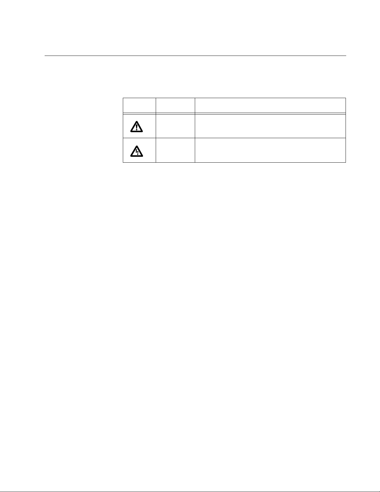
This document uses the safety symbols defined in Table 1.
Table 1. Safety Symbols
Symbol Meaning Description
Caution Performing or omitting a specific action may
result in equipment damage or loss of data.
Warning Performing or omitting a specific action may
result in electrical shock.
AT-9400 Series Gigabit Ethernet Switches Installation Guide
11
Page 12

Preface
Where to Find Web-based Guides
The installation and user guides for all Allied Telesis products are
available in portable document format (PDF) on our web site at
www.alliedtelesis.com. You can view the documents online or download
them onto a local workstation or server.
12
Page 13

AT-9400 Series Gigabit Ethernet Switches Installation Guide
Contacting Allied Telesis
This section provides Allied Telesis contact information for technical
support as well as sales or corporate information.
Online Support You can request technical support online by accessing the Allied Telesis
Knowledge Base from the following web site:
www.alliedtelesis.com/support. You can use the Knowledge Base to
submit questions to our technical support staff and review answers to
previously asked questions.
Email and
Telephone
Support
Returning
Products
For Sales or
Corporate
For Technical Support via email or telephone, refer to the Allied Telesis
web site: www.alliedtelesis.com. Select your country from the list
displayed on the website. Then select the appropriate menu tab.
Products for return or repair must first be assigned a Return Materials
Authorization (RMA) number. A product sent to Allied Telesis without a
RMA number will be returned to the sender at the sender’s expense.
To obtain an RMA number, contact the Allied Telesis Technical Support
group at our web site: www.alliedtelesis.com/support/rma. Select your
country from the list displayed on the website. Then select the appropriate
menu tab.
You can contact Allied Telesis for sales or corporate information at our
web site: www.alliedtelesis.com. Select your country from the list
displayed on the website. Then select the appropriate menu tab.
Information
Warranty The AT-9400 Switch has a Lifetime Warranty (two years fan and PSU). Go
to www.alliedtelesis.com/warranty for the specific terms and conditions
of the warranty and for warranty registration.
Management
Software Updates
New releases of management software for our managed products are
available from either of the following Internet sites:
r Allied Telesis web site: www.alliedtelesis.com
r Allied Telesis FTP server: ftp://ftp.alliedtelesis.com
If you prefer to download new software from the Allied Telesis FTP server
from your workstation’s command prompt, you will need FTP client
software and you must log in to the server. Enter “anonymous” for the user
name and your email address for the password.
13
Page 14

Preface
14
Page 15

Chapter 1
Overview
The AT-9400 Switches are managed Gigabit Ethernet switches for
Ethernet, Fast Ethernet, and Gigabit Ethernet networks. The AT-9400
Switches are divided into two groups:
Layer 2+ Switches
– AT-9408LC/SP
– AT-9424T/GB
– AT-9424T/SP
Basic Layer 3 Switches
– AT-9424T
– AT-9424T/POE
– AT-9424Ts
– AT-9424Ts/XP
– AT-9448T/SP
– AT-9448Ts/XP
The differences between the two groups are explained in the AT-S63
Management Software Features Guide.
This chapter has the following sections:
“Descriptions” on page 17
“10/100/1000Base-T Twisted Pair Ports” on page 26
“Fiber Optic Ports” on page 28
“GBIC Transceiver Slots” on page 29
“SFP Transceiver Slots” on page 30
“XFP Transceiver Slots” on page 31
“Redundant Twisted Pair Ports” on page 32
“Compact Flash Card Slot” on page 34
“Port LEDs” on page 35
“System LEDs” on page 37
“Stack LEDs” on page 38
“Expansion Slot” on page 39
“Terminal Port” on page 40
15
Page 16

Chapter 1: Overview
“Power Over Ethernet” on page 41
“AT-RPS3204 Redundant Power Supply” on page 43
“AC Power Connector” on page 44
16
Page 17
Descriptions
100-240VAC
~
RPS INPUT
462
AT-9408LC/SP
COMPACT FLASH
FAULT
MASTER
RPS
POWER
EJECT
STATUS
TERMINAL
PORT
12345678
9101112
PORT ACTIVITY
CLASS 1
LASER PRODUCT
SFP SFP SFP SFP
L/AL/AL/AL/AL/AL/AL/AL/AL/AL/AL/AL/A
LINK / ACT
L/A
461
Gigabit Ethernet Switch
System LEDs
Compact Flash
Card Slot
RJ-45 Style
Serial
Terminal Port
1000Base-SX Fiber Optic Ports
AC Power Connector
RPS Connector
SFP Transceiver Slots
Port LED (one per port)
AT-9400 Series Gigabit Ethernet Switches Installation Guide
The following sections describe the AT-9400 Switches.
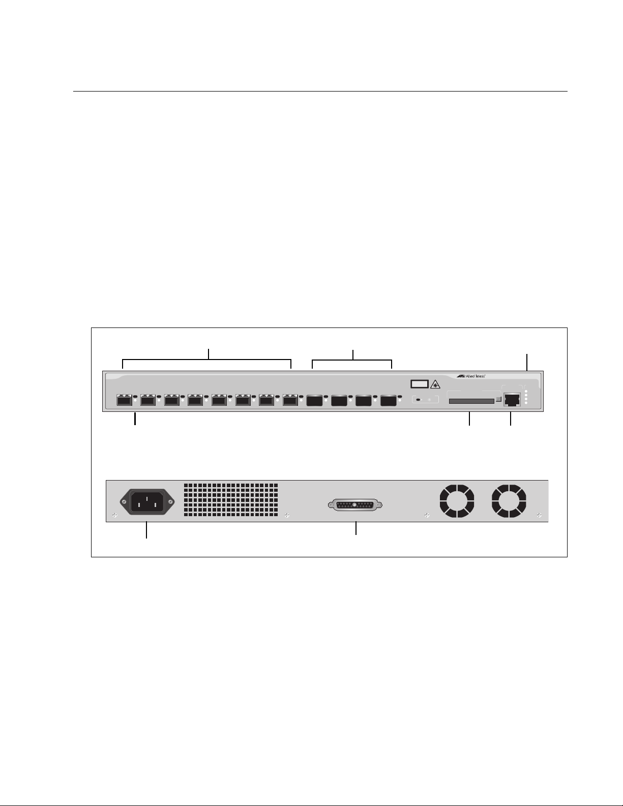
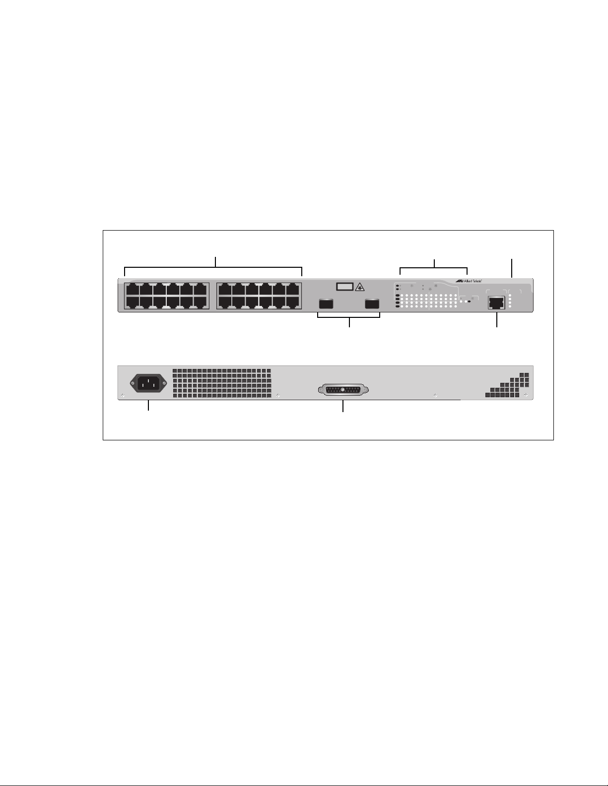
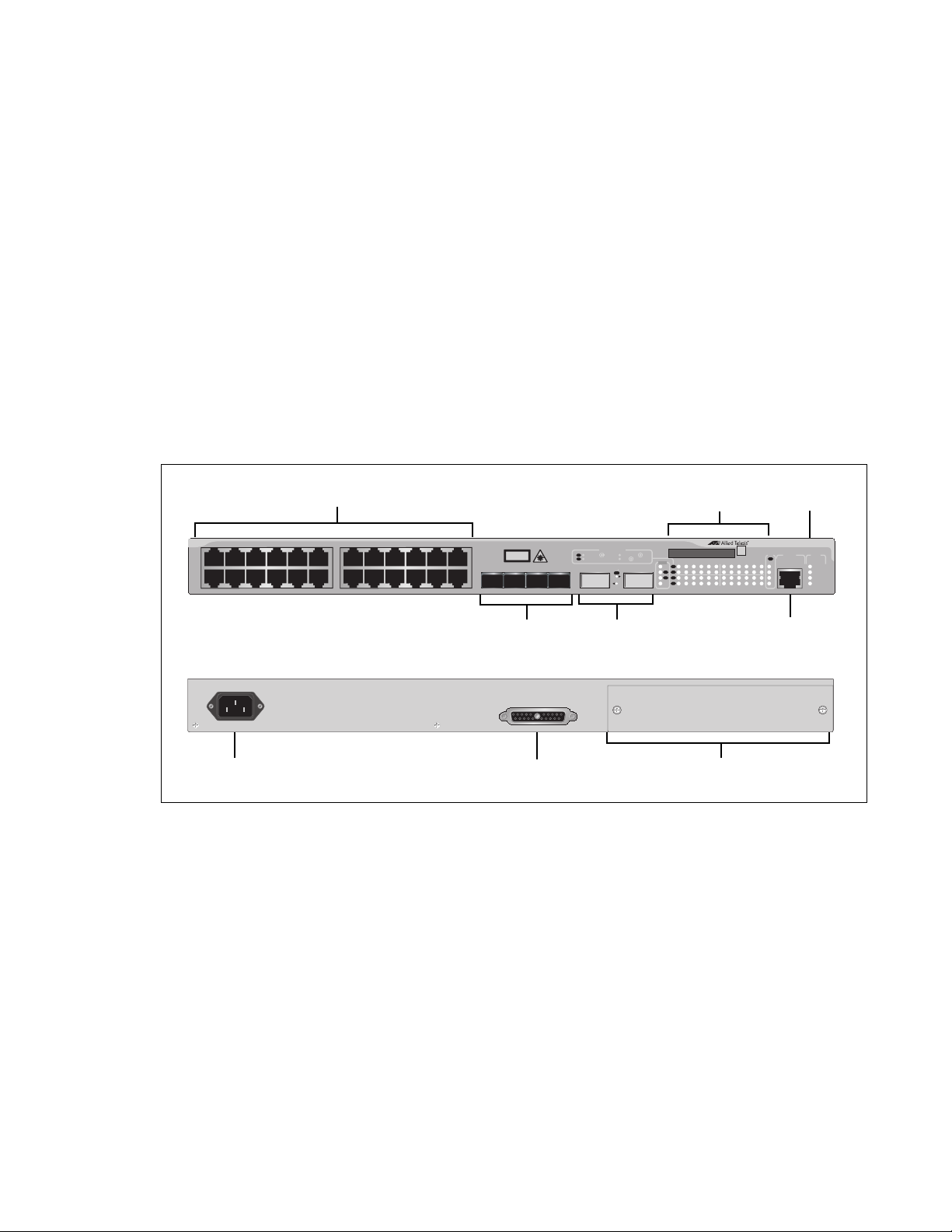
AT-9408LC/SP
Switch
The AT-9408LC/SP Layer 2+ Switch has the following hardware features:
Eight 1000Base-SX fiber optic ports with LC-duplex connectors
Four small form-factor pluggable (SFP) transceiver slots
An RJ-45 style serial terminal port for local (out-of-band) management
Status LEDs for the ports, SFP transceiver slots, and system
Redundant power supply (RPS) connector
Compact flash card slot
The front and back panels of the AT-9408LC/SP Switch are shown in
Figure 1.
Figure 1 AT-9408LC/SP Switch - Front and Back Panels
17
Page 18
Chapter 1: Overview
AC Power
Connector
RPS Connector
10/100/1000Base-T Ports
GBIC Transceiver Slots
Port and Transceiver
FAULT
RPS
MASTER
POWER
GBIC
23
GBIC
24
CLASS 1
LASER PRODUCT
STATUS
TERMINAL
PORT
1357911
2468 10 12
13 15 17 19 21 23R
14 16 18 20 22 24R
AT-9424T/GB
G
i
gabit
E
thernet
S
witc
h
1 3 5 7 9 11 13 15 17 19 21 23R
2468 10 12 14 16 18 20 22 24R
23 24
L/A
D/C
D/C
L/A
D/C
L/A
1000 LINK / ACT
HDX /
COL
FDX
10/100 LINK / ACT
PORT ACTIVITY
L/A
1000 LINK / ACT
GBIC
RJ-45 Style Serial
Terminal Port
System
LEDs
Slot LEDs
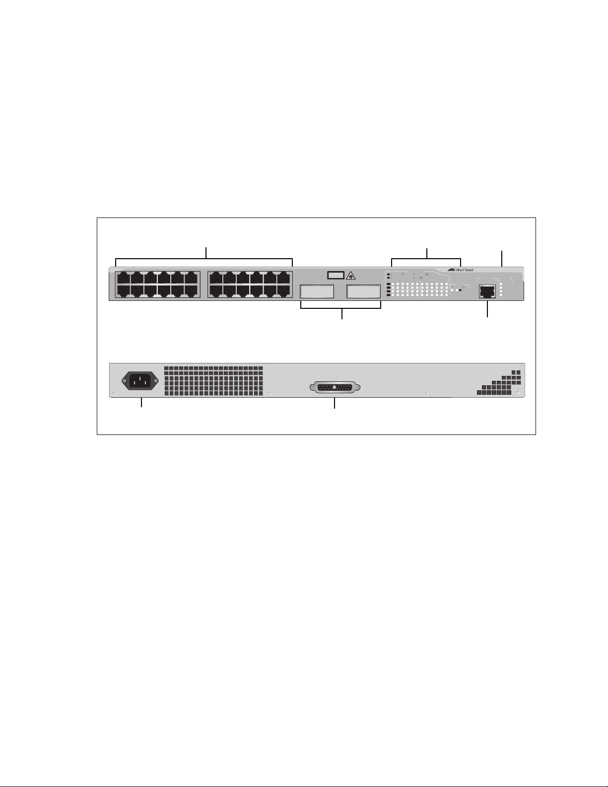
AT-9424T/GB
Switch
The AT-9424T/GB Layer 2+ Switch has the following hardware features:
24 10/100/1000Base-T ports
Two gigabit interface connector (GBIC) transceiver slots
An RJ-45 style serial terminal port for local (out-of-band) management
Status LEDs for the ports, transceiver slots, and system
Redundant power supply connector
Figure 2 shows the front and back panels of the AT-9424T/GB Switch.
100-240VAC~
RPS INPUT
Figure 2 AT-9424T/GB Switch - Front and Back Panels
18
Page 19
AT-9400 Series Gigabit Ethernet Switches Installation Guide
10/100/1000Base-T Ports
Port and SFP
RJ-45 Style Serial
Terminal Port
SFP Transceiver Slots
AC Power
Connector
RPS Connector
Slot LEDs
System
LEDs
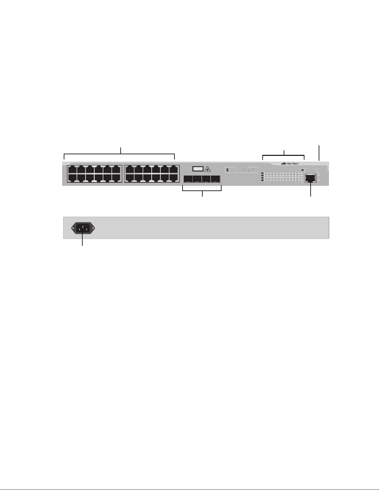
AT-9424T/SP
Switch
1357911
2468 10 12
The hardware features of the AT-9424T/SP Layer 2+ Switch include:
24 10/100/1000Base-T ports
Two Gigabit Ethernet small form-factor pluggable (SFP) transceiver
slots
An RJ-45 style serial terminal port for local (out-of-band) management
Status LEDs for the ports, transceiver slots, and system
Redundant power supply connector
Figure 3 shows the front and back panels of the AT-9424T/SP Switch.
13 15 17 19 21 23R
14 16 18 20 22 24R
PORT ACTIVITY
L/A
1000 LINK / ACT
CLASS 1
LASER PRODUCT
SFP
23
SFP
24
10/100 LINK / ACT
D/C
HDX /
COL
FDX
1 3 5 7 9 11 13 15 17 19 21 23R
L/A
D/C
L/A
D/C
2468 10 12 14 16 18 20 22 24R
1000 LINK / ACT
23 24
SFP
L/A
AT-9424T/SP
TERMINAL
PORT
G
i
gabit
E
thernet
S
witc
h
STATUS
FAULT
MASTER
RPS
POWER
100-240VAC~
RPS INPUT
Figure 3 AT-9424T/SP Switch - Front and Back Panels
19
Page 20
Chapter 1: Overview
1 3 5 7 9 11 13 15 17 19 21R 23R
2468 10 12 14 16 18 20 22R 24R
CLASS 1
LASER PRODUCT
AT-9424T
1 3 5 7 9111315171921R23R
2468 10 12 14 16 18 20 22R 24R
TERMINAL
PORT
FAULT
MASTER
POWER
STATUS
SFP
21 22 23 24
L/A
D/C
D/C
L/A
D/C
L/A
1000 LINK / ACT
HDX /
COL
FDX
10/100 LINK / ACT
PORT ACTIVITY
21
22
23
24
SFP
L/A
Gigabit Ethernet Switch
1282
10/100/1000Base-T Ports
Port and SFP
Slot LEDs
System
LEDs
SFP Transceiver Slots
RJ-45 Style Serial
Terminal Port
AC Power
Connector
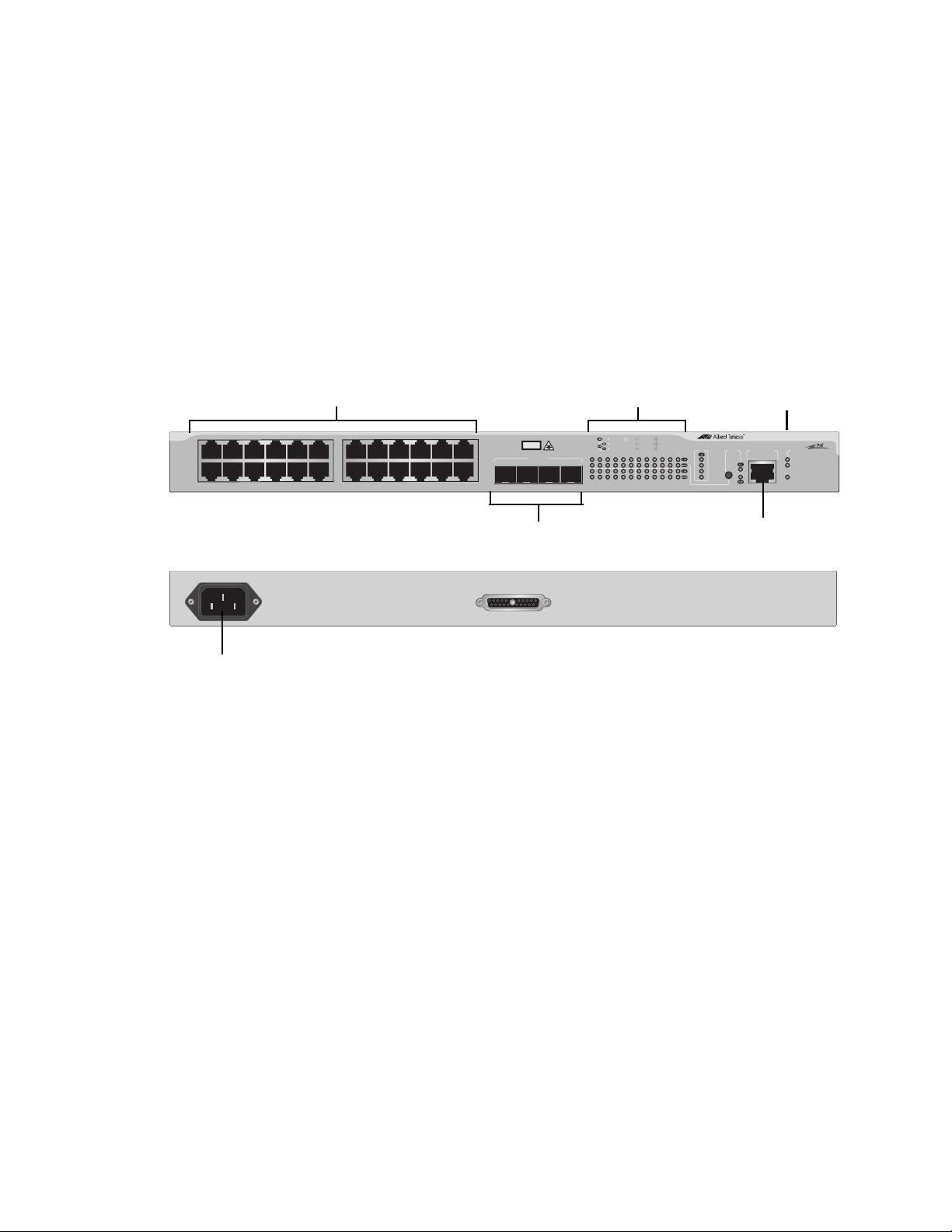
AT-9424T Switch The AT-9424T Basic Layer 3 Switch has these hardware features:
24 10/100/1000Base-T ports
Four Gigabit Ethernet small form-factor pluggable (SFP) transceiver
slots
An RJ-45 style serial terminal port for local (out-of-band) management
Status LEDs for the ports, transceiver slots, and system
Figure 6 shows the front and back panels of the AT-9424T Switch.
100-240VAC~
Figure 4 AT-9424T Switch - Front and Back Panels
1283
20
Page 21
AT-9400 Series Gigabit Ethernet Switches Installation Guide
100-240VAC
~
1333
RPS INPUT
AC POWER
CONNECTOR
SFP Transceiver Slots
10/100/1000Base-T POE Ports
Port and SFP
Slot LEDs
RJ-45 Style Serial
Terminal Port
System
LEDs
AT-9424T/POE
Switch
1357911
2468 10 12
The AT-9424T/POE Basic Layer 3 Switch has these hardware features:
24 10/100/1000Base-T ports with Power over Ethernet (PoE)
capability. (For a description of this feature, refer to “Power Over
Ethernet,” on page
Four Gigabit Ethernet small form-factor pluggable (SFP) transceiver
slots
An RJ-45 style serial terminal port for local (out-of-band) management
Status LEDs for the ports, transceiver slots, and system
Figure 5 shows the front and back panels of the AT-9424T/POE Switch
13 15 17 19 21R 23R
14 16 18 20 22R 24R
CLASS 1
LASER PRODUCT
1000 Base-X
21 22 23 24
SFP
1000 LINK ACT 10/100 LINK ACT
FDX
PD ON MAX CURRENTPD ERR
1 3 5 7 9 11 13 15 17 19 21R 23R
2468 10 12 14 16 18 20 22R 24R
COL
HDX
SFP
21
22
23
24
AT-9424T/POE Layer 3 Gigabit Ethernet Switch
MODE
TERMINAL PORT
STATUS
FAULT
MASTER
POWER
1332
Figure 5 AT-9424T/POE Switch - Front and Back Panels
21
Page 22
Chapter 1: Overview
10/100/1000Base-T Ports
Port and SFP
RJ-45 Style Serial
Terminal Port
SFP Transceiver Slots
AC Power
Connector
RPS Connector
Slot LEDs
System
LEDs
1 3 5 7 9 11 13 15 17 19 21R 23R
2468 10 12 14 16 18 20 22R 24R
CLASS 1
LASER PRODUCT
AT-9424Ts
Gigabit Ethernet Switch
1 3 5 7 9 11 13 15 17 19 21R 23R
2468 10 12 14 16 18 20 22R 24R
EJECT
TERMINAL
PORT
COMPACT FLASH
FAULT
RPS
MASTER
POWER
STATUS
SFP
21 22 23 24
L/A
D/C
D/C
L/AL/A
D/C
L/A
1000 LINK /
ACT
HDX /
COL
FDX
10/100 LINK / ACT
PORT ACTIVITY
STACK
PRES
MSTR
21
22
23
24
SFP
L/A
1
2
L/A
RPS INPUT
100-240VAC~
Expansion Slot
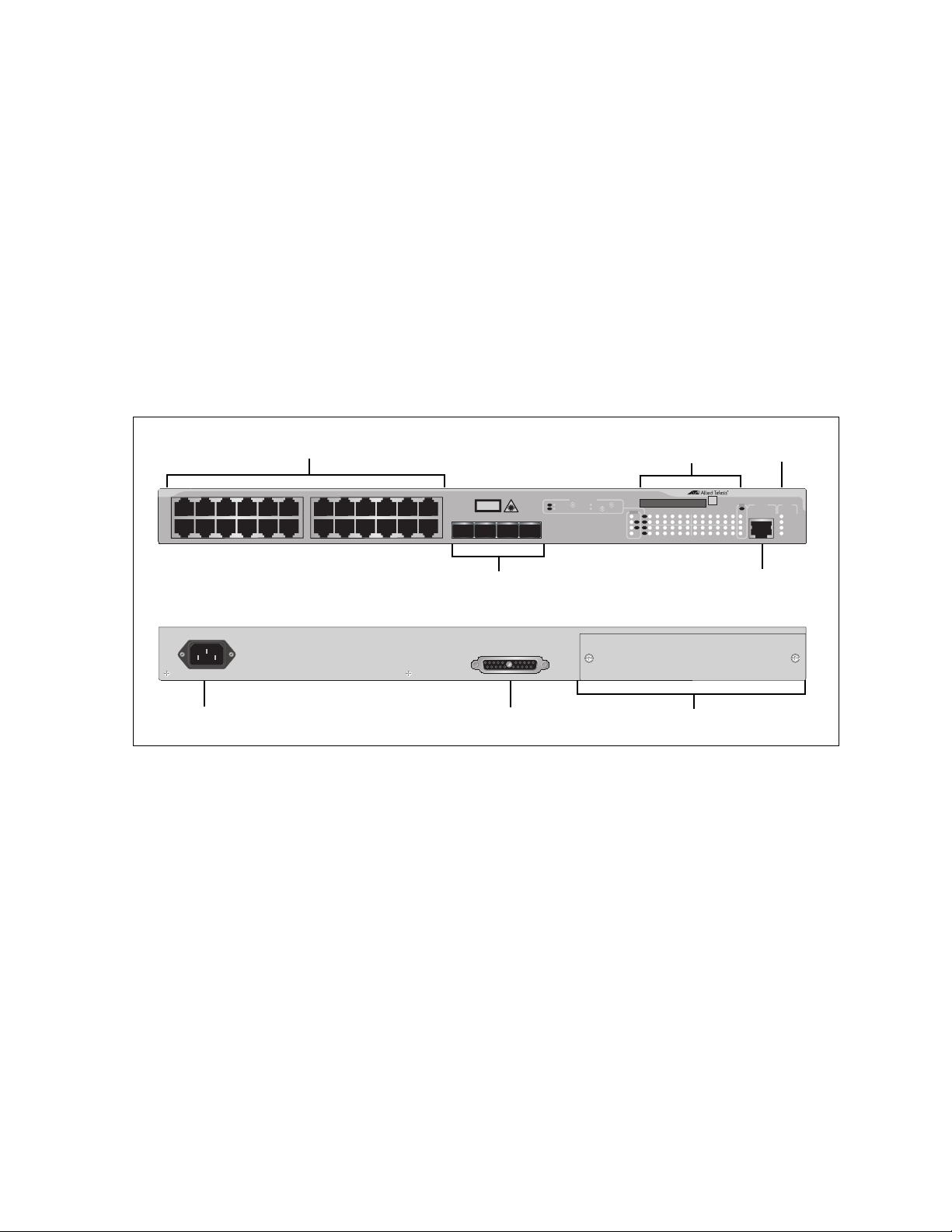
AT-9424Ts
Switch
The AT-9424Ts Basic Layer 3 Switch has these hardware features:
24 10/100/1000Base-T ports
Four Gigabit Ethernet small form-factor pluggable (SFP) transceiver
slots
An RJ-45 style serial terminal port for local (out-of-band) management
Status LEDs for the ports, transceiver slots, and system
Redundant power supply connector
Compact flash card slot
Expansion slot for the AT-StackXG Stacking Module
Figure 6 shows the front and back panels of the AT-9424Ts Switch.
22
Figure 6 AT-9424Ts Switch - Front and Back Panels
Page 23
AT-9400 Series Gigabit Ethernet Switches Installation Guide
10/100/1000Base-T Ports
Port and SFP
RJ-45 Style Serial
Terminal Port
SFP Slots
AC Power
Connector
RPS Connector
Slot LEDs
System
LEDs
1 3 5 7 9 11 13 15 17 19 21R 23R
2468 10 12 14 16 18 20 22R 24R
CLASS 1
LASER PRODUCT
AT-9424Ts/XP
Gigabit Ethernet Switch
1 3 5 7 9 11 13 15 17 19 21R 23R
2468 10 12 14 16 18 20 22R 24R
EJECT
TERMINAL
PORT
COMPACT FLASH
FAULT
RPS
MASTER
POWER
STATUS
SFP
21 22 23 24
L/A
D/C
D/C
L/AL/A
D/C
L/A
1000 LINK /
ACT
HDX /
COL
FDX
10/100 LINK / ACT
PORT ACTIVITY
STACK
PRES
MSTR
21
22
23
24
SFP
L/A
1
2
L/A
L/A
25 26
XFP
XFP
XFP Slots
RPS INPUT
100-240VAC~
Expansion Slot
AT-9424Ts/XP
Switch
The AT-9424Ts/XP Basic Layer 3 Switch has these hardware features:
24 10/100/1000Base-T ports
Four Gigabit Ethernet small form-factor pluggable (SFP) transceiver
slots
Two 10 Gigabit Ethernet small form factor pluggable (XFP) transceiver
slots
An RJ-45 style serial terminal port for local (out-of-band) management
Status LEDs for the ports, transceiver slots, and system
Redundant power supply connector
Compact flash card slot
Expansion slot for the AT-StackXG Stacking Module
Figure 7 shows the front and back panels of the AT-9424Ts/XP Switch.
Figure 7 AT-9424Ts/XP Switch - Front and Back Panels
23
Page 24
Chapter 1: Overview
AC Power
Connector
RPS Connector
10/100/1000Base-T Ports
SFP Transceiver
RJ-45 Style Serial
Terminal Port
Slots and LEDs
System LEDs
RPS INPUT
100-240VAC~
AT-9448T/SP
COMPACT FLASH
TERMINAL PORT
EJECT
45
48
15135791113 17 3331 47R3519 21 23 25 27 29 37 39 41 43 45R
1000 LINK / ACT
10/100 LINK / ACT
FDX
HDX / COL
D/C
L/A
L/A D/C
CLASS 1
LASER PRODUCT
L/A
SFP
LINK / ACT
34
48R36 38 40 42 44 46R
3216
2 4 6 8 10 12 14 22 24 26 28 30
18
20
L/A
STATUS
FLT
MSTR
RPS
PWR
47
46
L/A
SFP
L/A
SFP
L/A
SFP
Compact Flash
Card Slot
Port
LEDs
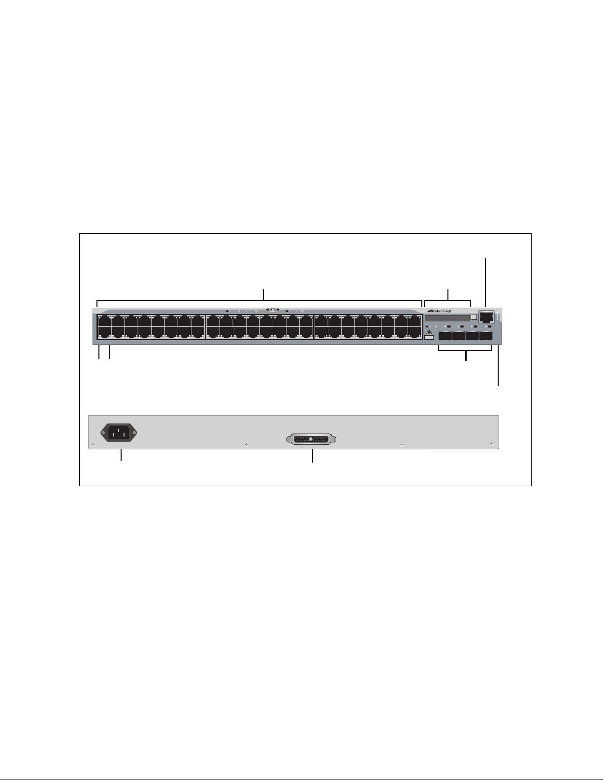
AT-9448T/SP
Switch
The hardware features of the AT-9448T/SP Basic Layer 3 Switch include:
48 10/100/1000Base-T ports
Four Gigabit Ethernet SFP transceiver slots
An RJ-45 style serial terminal port for local (out-of-band) management.
Status LEDs for the ports, transceiver slots, and system
Redundant power supply (RPS) connector
Compact flash card slot
Figure 8 shows the front and back panels of the AT-9448T/SP Switch.
24
Figure 8 AT-9448T/SP Switch - Front and Back Panels
Page 25
AT-9400 Series Gigabit Ethernet Switches Installation Guide
Port
LEDs
AC Power
Connector
RPS Connector
10/100/1000Base-T Ports
XFP Transceiver
RJ-45 Style Serial
Terminal Port
Slots and LEDs
System LEDs
AT-9448Ts/XP
STATUS
FAULT
MASTER
RPS
POWER
COMPACT FLASH
TERMINAL PORT
EJECT
49 50
15135791113 17 3331 473519 21 23 25 27 29 37 39 41 43 45
1000 LINK / ACT
10/100 LINK / ACT
FDX
HDX / COL
D/C
L/A
L/A D/C
CLASS 1
LASER PRODUCT
L/A
XFP XFP
LINK / ACT
STACK
PRES
L/A
L/A
34
4836 38 40 42 44 46
3216
2 4 6 8 10 12 14 22 24 26 28 30
18
20
1
2
MSTR
Expansion Slot
Compact Flash
Card Slot
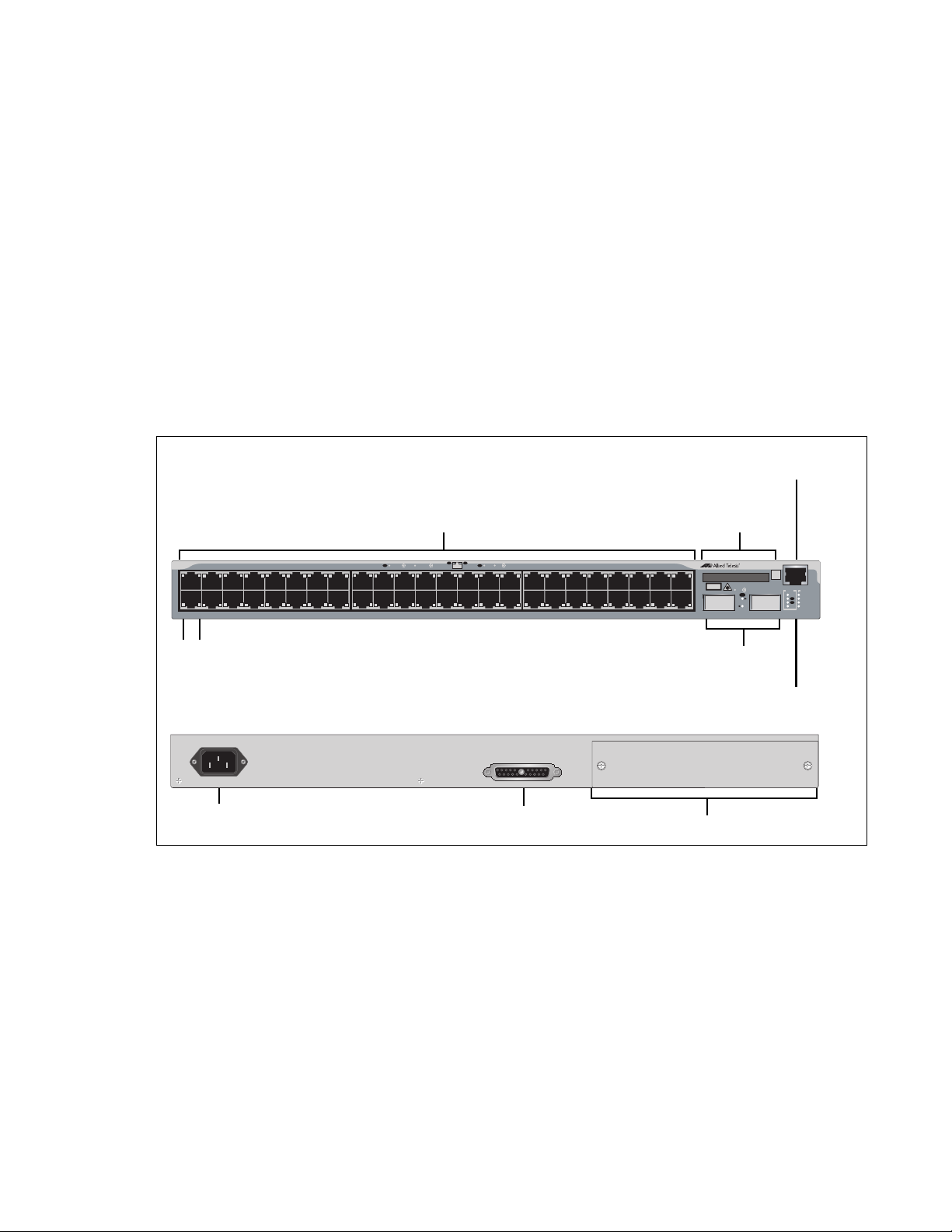
AT-9448Ts/XP
Switch
The AT-9448Ts/XP Basic Layer 3 Switch has the following hardware
features:
48 10/100/1000Base-T ports
Two 10 Gigabit Ethernet small form factor pluggable (XFP) transceiver
slots
An RJ-45 style serial terminal port for local (out-of-band) management
Status LEDs for the ports, transceiver slots, and system
Redundant power supply connector
Compact flash card slot
Expansion slot for the AT-StackXG Stacking Module
Figure 9 shows the front and back panels of the AT-9448Ts/XP Switch.
100-240VAC~
Figure 9 AT-9448Ts/XP Switch - Front and Back Panels
RPS INPUT
25
Page 26

Chapter 1: Overview
Note
Note
10/100/1000Base-T Twisted Pair Ports
This section describes the twisted pair ports on the switches. (This section
does not apply to the AT-9408LC/SP Switch.)
Connector Type The ports are 8-pin RJ-45 connectors that use four pins at 10 or 100 Mbps
and all eight pins at 1000 Mbps. For the pin assignments, refer to “RJ-45
Twisted Pair Port Pinouts” on page 80.
Speed A port’s speed can be 10, 100, or 1000 Mbps. The speed can be set
automatically through Auto-Negotiation, the default setting, or manually
with the AT-S63 Management Software.
To operate at 1000 Mbps, a twisted pair port must be set to Auto Negotiation. The speed of a twisted pair port cannot be manually set
to 1000 Mbps.
Duplex Mode A twisted pair port can operate in either half- or full-duplex mode. (Full-
duplex mode is the only mode available when a port is operating at 1000
Mbps.) The twisted pair ports are IEEE 802.3u-compliant and AutoNegotiate the duplex mode setting.
You can disable Auto-Negotiation on one or all of the switch ports so that
you can set the duplex mode manually through the AT-S63 Management
Software.
In order for a switch port to successfully Auto-Negotiate its duplex
mode with a 10 or 100 Mbps end node, the end node should also be
configured for Auto-Negotiation. Otherwise, a duplex mode
mismatch can occur. A switch port using Auto-Negotiation defaults
to half-duplex if it detects that the end node is not using AutoNegotiation. This results in a mismatch if the end node is operating
at a fixed duplex mode of full-duplex.
To avoid this problem when connecting an end node with a fixed
duplex mode of full-duplex to a switch port, use the AT-S63
Management Software to disable Auto-Negotiation on the port and
set the port speed and duplex mode manually.
26
Page 27

AT-9400 Series Gigabit Ethernet Switches Installation Guide
Maximum
The ports have a maximum operating distance of 100 meters (328 feet).
Distance
Cable Type The cabling requirements for a 10/100/1000Base-T port are:
For 10 Mbps operation: Standard TIA/EIA 568-B-compliant Category 3
or better shielded or unshielded cabling with 100 ohm impedance and
a frequency of 16 MHz.
For 100 Mbps operation: Standard TIA/EIA 568-A-compliant Category
5 or TIA/EIA 568-B-compliant Enhanced Category 5 (Cat 5e) shielded
or unshielded cabling with 100 ohm impedance and a frequency of 100
MHz.
For 1000 Mbps operation: Standard TIA/EIA 568-A-compliant
Category 5 or TIA/EIA 568-B-compliant Enhanced Category 5 (Cat 5e)
shielded or unshielded cabling with 100 ohm impedance and a
frequency of 100 MHz.
Auto-MDI/
MDI-X
The twisted pair ports on the switch are IEEE 802ab-compliant and feature
auto-MDI/MDI-X. This feature, available when a port’s speed and duplex
mode are set through Auto-Negotiation, automatically configures a switch
port to MDI or MDI-X depending on the wiring configuration of the port on
the end node. This allows you to connect any network device to a port on
the switch using a straight-through twisted pair cable.
If Auto-Negotiation is disabled on a port and the speed and duplex mode
are set manually, the auto-MDI/MDI-X feature is also disabled and the
port’s wiring configuration defaults to the MDI-X setting. This setting can
be configured with the AT-S63 Management Software.
Port Pinouts Refer to Table 13 on page 80 for the port pinouts when a twisted pair port
operates at 10 or 100 Mbps in the MDI configuration and Table 14 on
page 80 for the MDI-X configuration. For port pinouts when a twisted pair
port operates at 1000 Mbps, refer to Table 15 on page 81.
27
Page 28

Chapter 1: Overview
Note
Fiber Optic Ports
This section applies to ports 1 through 8 on the AT-9408LC/SP Switch.
Connector Type The ports feature LC-duplex connectors.
Speed The ports have fixed speed of 1000 Mbps (1000Base-SX).
Maximum
Distance and
Cabling
The ports have a maximum distance of 275 meters (m) with 62.5/125 µm
(core/cladding) multimode fiber optic cable and 550m with 50/125 µm
multimode fiber optic cable.
For optical specifications, refer to “AT-9408LC/SP Switch
1000Base-SX Port Specifications” on page 82.
28
Page 29

GBIC Transceiver Slots
Note
For interconnecting devices over large distances using fiber optic cable,
the AT-9424T/GB Switch has two slots on the front panel labeled 23 and
24 for optional fiber optic Gigabit Interface Converter (GBIC) Ethernet
transceivers. Figure 10 illustrates a GBIC transceiver.
AT-9400 Series Gigabit Ethernet Switches Installation Guide
Figure 10 GBIC Transceiver
GBIC transceiver slots 23 and 24 are paired with twisted pair ports 23R
and 24R. Only one port or transceiver in a pair can be operational at a time
and a link on a transceiver port takes priority over a link on a twisted pair
port. For further information, refer to “Redundant Twisted Pair Ports” on
page 32.
For a list of supported GBIC transceivers, contact your Allied Telesis
sales representative.
29
Page 30

Chapter 1: Overview
Note
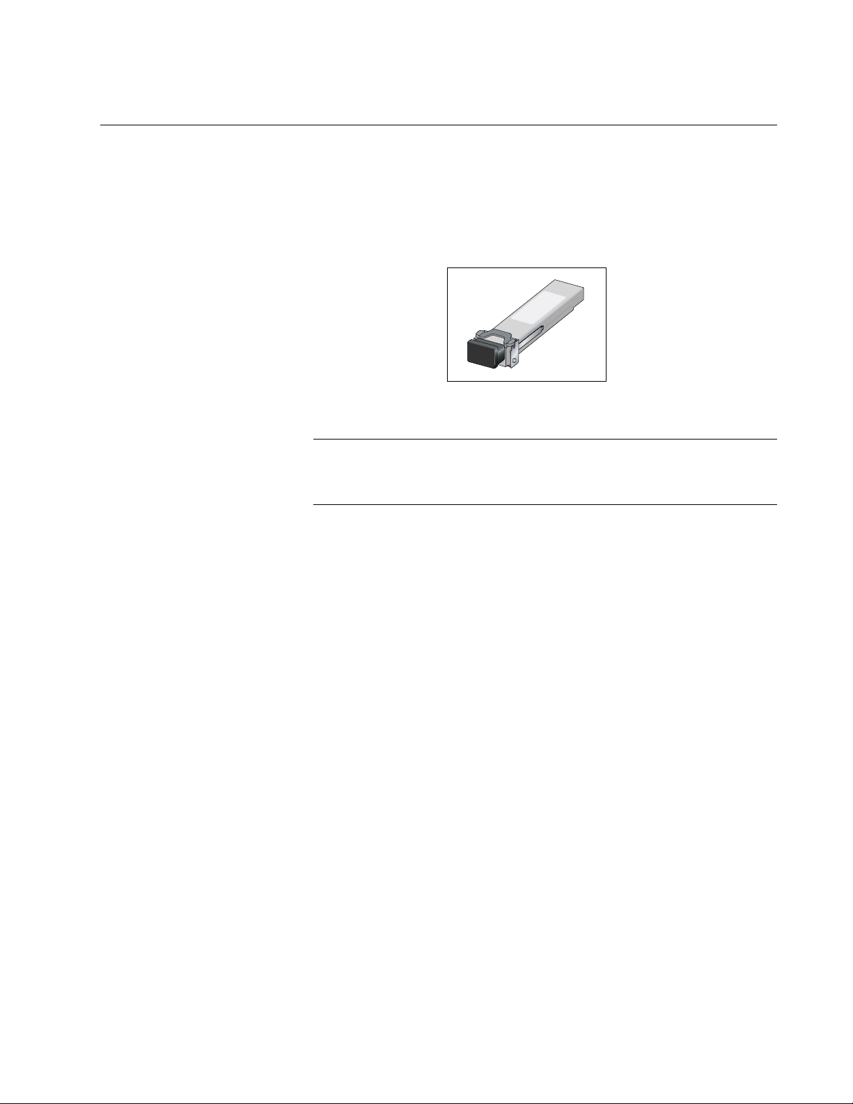
SFP Transceiver Slots
Several of the AT-9400 Switches feature slots for optional Gigabit
Ethernet SFP transceivers for interconnecting network devices over large
distances using fiber optic cable. With the exception of the AT-9408LC/SP
Switch, each SFP slot is paired with a twisted pair port. A link on an SFP
transceiver takes priority in the event both an SFP transceiver and its
paired twisted pair port have established links to their respective end
nodes. For further information, refer to “Redundant Twisted Pair Ports” on
page 32.
Figure 11 illustrates an SFP transceiver.
Figure 11 SFP Transceiver
For a list of supported SFP transceivers for the AT-9400 Switches,
contact your Allied Telesis sales representative.
30
Page 31
XFP Transceiver Slots
Note
Several AT-9400 Switches have slots for optional XFP 10 Gigabit Ethernet
transceivers to connect high speed, 10 gigabit devices to the switch or
create high speed backbone networks between switches.
Figure 12 shows an example of an XFP transceiver.
AT-9400 Series Gigabit Ethernet Switches Installation Guide
721
Figure 12 XFP Transceiver
For a list of supported XFP transceivers, contact your Allied Telesis
sales representative.
31
Page 32

Chapter 1: Overview
Redundant Twisted Pair Ports
Some AT-9400 Switches have two or four twisted pair ports that are paired
with GBIC or SFP slots. The twisted pair ports are identified with the letter
“R” for “Redundant” as part of their number on the front faceplate of the
unit. The ports and slots are listed in Table 2.
Table 2 Twisted Pair Ports Matched with GBIC and
Model Ports and Slots
AT-9424T/GB 23R with GBIC slot 23
AT-9424T/SP 23R with SFP slot 23
SFP Slots
24R with GBIC slot 24
24R with SFP slot 24
AT-9424T,
AT-9424Ts,
and
AT-9424Ts/XP
21R with SFP slot 21
22R with SFP slot 22
23R with SFP slot 23
24R with SFP slot 24
AT-9448T/SP 45R with SFP slot 45
46R with SFP slot 46
47R with SFP slot 47
48R with SFP slot 48
Follow these guidelines when using these ports and slots:
Only one port in a pair — either the twisted pair port or a
corresponding GBIC or SFP module — can be active at a time.
The twisted pair port is the active port when its GBIC or SFP slot is
empty, or when a GBIC or SFP module is installed but has not
established a link to an end node.
The twisted pair port automatically changes to the redundant status
mode when a GBIC or SFP module establishes a link with an end
node.
A twisted pair port automatically transitions back to the active status
when the link is lost on the GBIC or SFP module.
32
In nearly all cases, a twisted pair port and a GBIC or SFP module
share the same configuration settings, including port settings, VLAN
assignments, access control lists, and spanning tree.
An exception to the shared settings is port speed. If you disable Auto-
Negotiation on a twisted pair port and set the speed and duplex mode
manually, the speed reverts to Auto-Negotiation when a GBIC or SFP
module establishes a link with an end node.
Page 33

AT-9400 Series Gigabit Ethernet Switches Installation Guide
Note
These guidelines do not apply to the SFP slots on the
AT-9408LC/SP Switch and the XFP slots on the AT-9424Ts/XP and
AT-9448Ts/XP Switches.
33
Page 34

Chapter 1: Overview
Note
AT-9408LC/S
COMPACT FLASH
EJECT
TER
P
Compact Flash Card Slot
The compact flash card slot featured on many of the AT-9400 Switches
and shown in Figure 13 is used to store configuration files and AT-S63
Management Software image files on a compact flash card. A compact
flash memory card can make it easier for you to upgrade the files on a
switch or transfer files between AT-9400 Switches.
463
Figure 13 Compact Flash Card Slot
A flash memory card is not required for normal operations of the
switch.
The AT-9400 Switches support only the AT-CF128A 128MB compact
flash card from Allied Telesis. Contact your Allied Telesis sales
representative for more information.
To insert a compact flash card, position it so that the manufacturer’s brand
label is facing up and press it into the slot until the button marked “Eject”
pops out.
To remove the compact flash card, press the button marked “Eject” until it
is pressed in completely and then remove the compact flash card.
For information on how to transfer files to and from a flash memory card,
refer to the AT-S63 Management Software User’s Guides.
34
Page 35

Port LEDs
AT-9400 Series Gigabit Ethernet Switches Installation Guide
The following sections describe the twisted pair and fiber optic port LEDs.
10/100/1000Base-
T Twisted Pair
Port LEDs
A twisted pair port has two LEDs labeled L/A (link/activity) and D/C (duplex
mode/collisions). The L/A LED indicates the speed and activity on a port.
The D/C LED indicates the duplex mode (full- or half-duplex) and the
status of collisions on the port.
Table 3 describes the LEDs for the 10/100/1000Base-T twisted pair ports.
Table 3 Twisted Pair Port LEDs
LED Function State Description
L/A Link Status
and Activity
Off No link is established between the
port and the end node.
Solid
green
Flashing
green
Solid
amber
Flashing
amber
The port has established a link at
1000 Mbps.
Packets are being received or
transmitted at 1000 Mbps.
The port has established a link at 10
or 100 Mbps.
Packets are being received or
transmitted at 10 or 100 Mbps.
D/C Duplex
Mode and
Collisions
Green The port is operating in full-duplex
mode.
Amber The port is operating in half-duplex
mode. (Only when operating at 10 or
100 Mbps.)
Flashing
amber
Collisions are occurring on the port.
(Only when operating at 10 or 100
Mbps, half duplex mode.)
35
Page 36

Chapter 1: Overview
Fiber Optic Port
and Transceiver
Slot LEDs
The 1000Base-SX fiber optic ports on the AT-9408LC/SP Switch and the
GBIC and SFP transceiver slots have one LED. The LED is defined in
Table 4.
Table 4 1000Base-SX Port and GBIC and SFP Slot LED
LED Function State Description
L/A Link Status
and Activity
Each 10 Gigabit Ethernet transceiver slot on the AT-9424Ts/XP and
AT-9448Ts/XP Switches has one LED, defined in Table 5.
LED Function State Description
Off No link is established between the
port and the end node.
Solid
green
Flashing
green
Table 5 XFP Slot LED
The port has established a link at
1000 Mbps.
Packets are being received or
transmitted at 1000 Mbps.
L/A Link Status
and Activity
Off No link is established between the
port and the end node.
Solid
green
Flashing
green
The port has established a link at 10
Gbps.
Packets are being received or
transmitted at 10 Gbps.
36
Page 37

System LEDs
AT-9400 Series Gigabit Ethernet Switches Installation Guide
The system LEDs on the front panel display general status information, as
described in Table 6.
Table 6 System LEDs
LED State Description
FAULT or
FLT
MASTER
or MSTR
RPS Off No optional redundant power supply is
POWER
or PWR
Off Normal operation.
Solid
Red
Flashing
Red
Off The switch has an enhanced stacking status of
Green The switch has an enhanced stacking status of
Green An optional redundant power supply is
Off The switch is not receiving power.
Green The switch is receiving power.
The switch or management software has
malfunctioned. (Refer to Chapter 3,
“Troubleshooting” on page 67 for instructions
on how to troubleshoot a problem.)
The switch is saving its configuration or is
downloading a new version of the AT-S63
Management Software.
slave or unavailable.
master.
connected to the switch.
physically connected to the switch and may be
powered on or off.
37
Page 38

Chapter 1: Overview
Stack LEDs
The Stack LEDs reflect the status of the two Stack ports on the optional
AT-StackXG Stacking Module for the AT-9424Ts, AT-9424Ts/XP, and
AT-9448Ts/XP Switches. The module, which does not have LEDs, is used
to build a stack of up to five or eight devices. These LEDs remain off if the
optional module is not installed. For further information, refer to
“Expansion Slot” on page 39.
Table 7 Stack LEDs
LED State Description
MSTR Off The switch is not the master unit of the stack.
Green The switch is acting as the master unit of the
stack.
1 L/A Off Stack Port 1 has not established a link to a
stacking port on another AT-StackXG Stacking
Module.
Green Stack Port 1 has established a link to a
stacking port on another AT-StackXG Stacking
Module.
Flashing
Green
2 L/A Off Stack Port 2 has not established a link to a
Green Stack Port 2 has established a link to a
Flashing
Green
PRES Off The expansion slot for the AT-StackXG
Stack Port 1 has established a link to a
stacking port on another AT-StackXG Stacking
Module and is sending or receiving packet
traffic.
stacking port on another AT-StackXG Stacking
Module.
stacking port on another AT-StackXG Stacking
Module.
Stack Port 2 has established a link to a
stacking port on another AT-StackXG Stacking
Module and is sending or receiving packet
traffic.
Stacking Module is empty.
38
Green The AT-StackXG Stacking Module is installed
in the expansion slot.
Page 39

Expansion Slot
Note
AT-9400 Series Gigabit Ethernet Switches Installation Guide
The expansion slot on the AT-9424Ts, AT-9424Ts/XP, and AT-9448Ts/XP
Switches accommodates the optional AT-StackXG Stacking Module. The
module creates a stack of up to five or eight switches, depending on the
model. The switches of a stack function as a single, logical unit where
network functions, such as the spanning tree protocol and static port
trunks, can span across all the ports of the switches in the stack. This
increases network bandwidth and simplifies network management.
For further information and installation instructions, refer to the AT-9400
Stack Installation Guide.
Do not install the AT-StackXG Stacking Module into a switch until
you have read the Software Release Notes included with the latest
release of the AT-S63 Management Software. This module may not
be appropriate for all network environments because a stack does
not support all the features of the AT-S63 Management Software.
39
Page 40

Chapter 1: Overview
Note
Note
Terminal Port
The terminal port is used to establish a local (out-of-band) management
session with the switch and configure the switch’s operating parameters.
You establish a local management session with the switch by connecting
a terminal or a personal computer with a terminal emulation program to
the port.
You can use the AT-9400 Switch as an unmanaged switch if the
default settings of the AT-S63 Management Software are adequate
for your network. For a list of the default settings, refer to the AT-S63
Management Software Features Guide.
The terminal port has an RJ-45 style connector. An RJ-45 to RS-232
management cable is supplied with the switch.
The terminal port is set to the following specifications:
Default baud rate: 9600 bps (Range is 9600 to 115200 bps)
Data bits: 8
Parity: None
Stop bits: 1
Flow control: None
These settings are for a DEC VT100 or ANSI terminal, or an
equivalent terminal emulation program.
40
Page 41

Power Over Ethernet
The following discussion applies only to the AT-9424T/POE Gigabit
Ethernet switch.
The twisted pair ports on the AT-9424T/POE switch feature Power over
Ethernet (PoE). PoE is a mechanism for supplying power to network
devices over the same twisted pair cables used to carry network traffic.
This feature can simplify network installation and maintenance by allowing
you to use the switch as a central power source for other network devices.
A device that receives its power over an Ethernet cable is called a
powered device. Examples of such devices can be wireless access points,
IP telephones, web cams, and even other Ethernet switches. A powered
device connected to a port on the switch will receive both network traffic
and power over the same twisted pair cable.
There are several advantages that the PoE feature of the AT-9424T/POE
switch adds to the installation and maintenance of your network. First,
because the switch acts as the central power source for your powered
devices, adding an uninterruptible power source (UPS) to the switch
increases the protection not just to the switch itself from possible power
source problems but also to all of the powered devices connected to it.
This can increase the reliability of your network by minimizing the impact
to network operations from a power failure.
AT-9400 Series Gigabit Ethernet Switches Installation Guide
PoE can also simplify the installation of your network. A frequent issue in
selecting a location for a network device is whether there is a power
source nearby. This often limits equipment placement or requires the
added cost and time of having additional electrical sources installed. With
PoE, you can install PoE-compatible network equipment wherever they
are needed without having to worry about whether they are near a power
source.
The switch automatically determines whether or not a device connected to
a port is a powered device. A powered device has a signature resistor or
signature capacitor that the switch can detect over the Ethernet cabling. If
the resistor or capacitor is present, the switch assumes that the device is a
powered device.
Power Budgeting The AT-9424T/POE Gigabit Ethernet Switch provides a of 15.4 W
maximum of power per port on all 24 ports for a total power consumption
of 370 W, while at the same time furnishing standard 10/100/1000 Mbps
Ethernet functionality.
The AT-9424T/POE smart power management functionality supports any
combination of Ethernet ports (1-24) that supply power for IEEE 802.3af
Class 0, 1, 2, or 3 powered devices up to a maximum of 370 watts, as
41
Page 42

Chapter 1: Overview
described in Table 8. .
Table 8. IEEE 802.3af Class vs. Power Levels
Class Usage
Minimum Power
Levels Output at
the PSE
Maximum Power
Levels Output at
the PD
0 Default 15.4W 0.44W to 12.95W
1 Optional 4.0W 0.44W to 3.84W
2 Optional 7.0W 3.84W to 6.49W
3 Optional 15.4W 6.49W to 12.95W
A port connected to a network node that is not a powered device (that is, a
device that receives its power from another power source) functions as a
regular Ethernet port, without PoE. The PoE feature remains enabled on
the port but no power is delivered to the device.
Implementation A standard Ethernet twisted pair cable contains four pairs of strands for a
total of eight strands. 10/100/1000 Mbps network traffic requires only four
strands (1, 2, 3, and 6), leaving four strands in the cable unused (4, 5, 7,
and 8).
The PoE standard, IEEE 802.3af, describes two alternative ways for
delivering power to a powered device (PD) over twisted pair cabling.
Alternative A uses the same strands that carry the network traffic.
Alternative B uses the spare strands. The PoE implementation on the AT9424T/POE Gigabit Ethernet Switch is Alternative A, where power is
transmitted over strands 1, 2, 3, and 6.
42
PD’s that comply with the IEEE 802.3af standard typically support both
power delivery methods. So long as a PD is compliant with the standard, it
should be able to receive its power from the switch while using either a
straight or cross-over cable. The PoE feature on the AT-9424T/POE
Gigabit Ethernet Switch should also work with most legacy PD’s as long
as the device can be powered on pins 1, 2, 3, and 6. A legacy device is a
node that was manufactured before the IEEE 802.3af standard was
completed and, consequently, may not adhere to the standard. If this is
the case, a cross-over (MDI-X) cable may be needed to insure that the DC
polarity is correct.
Page 43
AT-RPS3204 Redundant Power Supply
AT-PW
R3204
P
O
W
E
R
The RPS connector on the back panel of the switch connects to the
optional AT-RPS3204 redundant power supply unit, shown in Figure 14.
The unit can provide power to the switch in the event that the switch’s
internal power supply fails.
The AT-RPS3204 redundant external power supply features one
preinstalled AT-PWR3204 Power Module and three empty slots for
additional power modules. Each power module can support one switch.
When fully populated with AT-PWR3204 Power Modules, the
AT-RPS3204 unit can support up to four switches simultaneously. For
information about installing an AT-RPS3204 unit, consult the
documentation shipped with the unit.
AT-9400 Series Gigabit Ethernet Switches Installation Guide
Figure 14 AT-RPS3204 Redundant Power Supply Unit
The pinouts for the redundant power supply’s 21-pin D-combo port and
connector are described in “RPS 21-pin D-combo Port and Connector
Pinouts” on page 83.
43
Page 44

Chapter 1: Overview
AC Power Connector
The AT-9400 Switches have a single AC power supply socket on the back
panel, which has autoswitch AC inputs. To power the switch on or off,
connect or disconnect the power cord.
Refer to “Technical Specifications” on page 77 for the input voltage range.
44
Page 45

Chapter 2
Installing the Switch
This chapter contains the installation procedures for the switch. The
chapter contains the following sections:
“Reviewing Safety Precautions” on page 46
“Selecting a Site” on page 49
“Twisted Pair and Fiber Optic Cable Specifications” on page 50
“Unpacking the Switch” on page 52
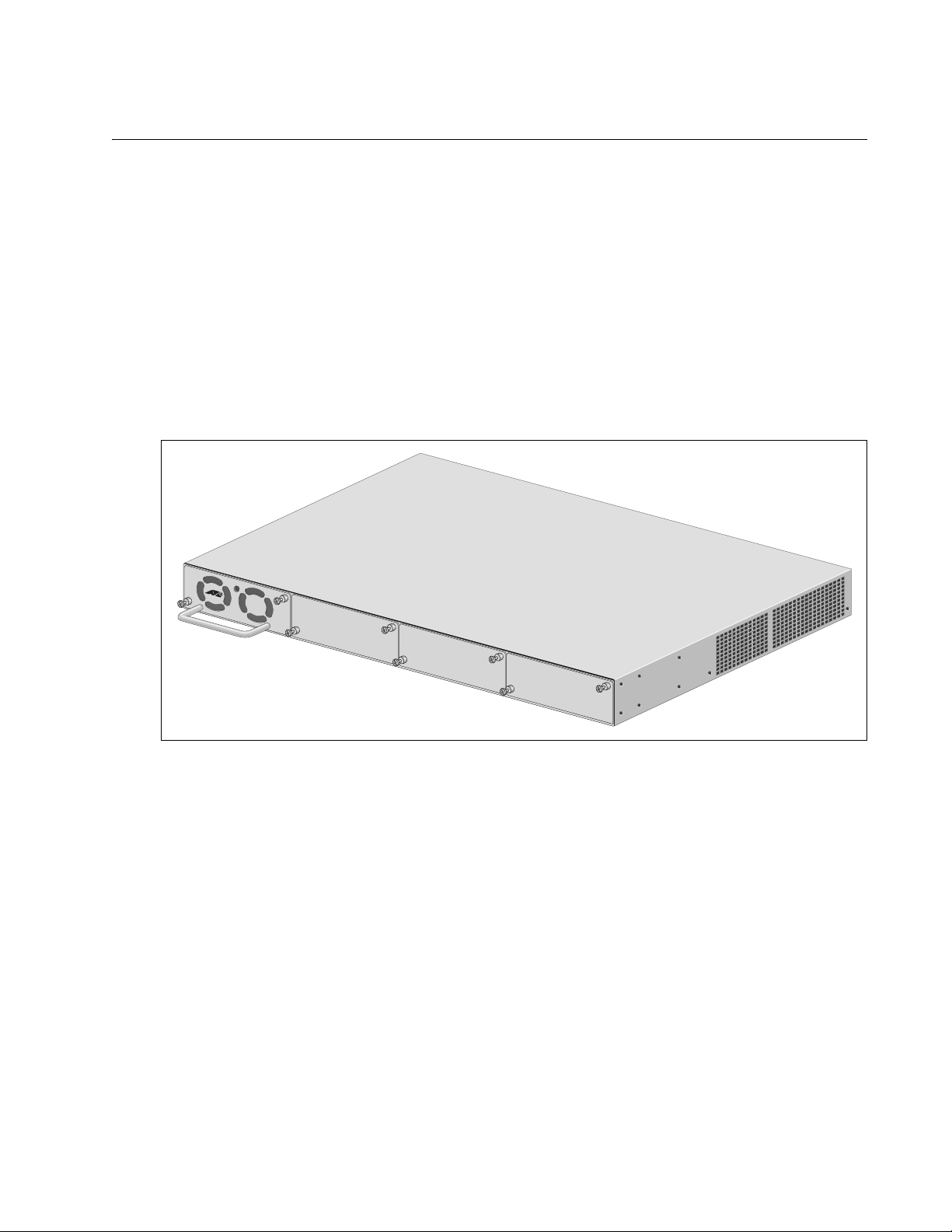
“Installing the Power Cord Retaining Clip (AC Switches Only)” on
page 53
“Installing the Switch in a Rack” on page 54
“Installing Optional Transceivers” on page 56
“Cabling the Twisted Pair or Fiber Optic Ports” on page 61
“Applying AC Power” on page 62
“Starting a Local Management Session” on page 64
“Warranty Registration” on page 66
45
Page 46
Chapter 2: Installing the Switch
Note
Reviewing Safety Precautions
Please review the following safety precautions before you begin to install
the switch or any of its components.
The indicates that a translation of the safety statement is
available in a PDF document titled “Translated Safety Statements”
(613-000990) posted on the Allied Telesis website at
www.alliedtelesis.com. This document is also included with the
documentation CD that is shipped with the product.
Warning: Class 1 Laser product.
Warning: Do not stare into the laser beam.
Warning: To prevent electric shock, do not remove the cover. No
user-serviceable parts inside. This unit contains hazardous
voltages and should only be opened by a trained and qualified
technician. To avoid the possibility of electric shock, disconnect
electric power to the product before connecting or disconnecting
E1
E2
the LAN cables.
Warning: Do not work on equipment or cables during periods of
lightning activity.
Warning: Power cord is used as a disconnection device. To deenergize equipment, disconnect the power cord.
Warning: Class I Equipment. This equipment must be earthed.
The power plug must be connected to a properly wired earth
ground socket outlet. An improperly wired socket outlet could
place hazardous voltages on accessible metal parts.
L1
L2
E3
E4
46
Pluggable Equipment. The socket outlet shall be installed near
E5
E6
the equipment and shall be easily accessible.
Caution: Air vents must not be blocked and must have free
access to the room ambient air for cooling.
Page 47

AT-9400 Series Gigabit Ethernet Switches Installation Guide
Warning: Operating Temperature. This product is designed for a
maximum ambient temperature of 40° degrees C.
All Countries: Install product in accordance with local and
National Electrical Codes.
Circuit Overloading: Consideration should be given to the
connection of the equipment to the supply circuit and the effect
that overloading of circuits might have on overcurrent protection
and supply wiring. Appropriate consideration of equipment
nameplate ratings should be used when addressing this
concern.
Caution: Risk of explosion if battery is replaced by an incorrect
type. Replace only with the same or equivalent type
recommended by the manufacturer. Dispose of used batteries
according to the manufacturer’s instructions.
E21
E8
E7
Attention: Le remplacement de la batterie par une batterie de
type incorrect peut provoquer un danger d’explosion. La
remplacer uniquement par une batterie du même type ou de
type équivalent recommandée par le constructeur. Les batteries
doivent être éliminées conformément aux instructions du
constructeur.
Warning: Mounting of the equipment in the rack should be such
that a hazardous condition is not created due to uneven
mechanical loading.
Warning: This unit might have more than one power cord. To
reduce the risk of electric shock, disconnect all power cords
before servicing the unit.
If installed in a closed or multi-unit rack assembly, the operating
ambient temperature of the rack environment may be greater
than the room ambient temperature. Therefore, consideration
should be given to installing the equipment in an environment
compatible with the manufacturer’s maximum rated ambient
temperature (Tmra).
E22
E25
E35
E30
Caution: Installation of the equipment in a rack should be such
that the amount of air flow required for safe operation of the
equipment is not compromised.
E36
47
Page 48

Chapter 2: Installing the Switch
Warning: Reliable earthing of rack-mounted equipment should
be maintained. Particular attention should be given to supply
connections other than direct connections to the branch circuits
(e.g., use of power strips).
E37
48
Page 49

Selecting a Site
AT-9400 Series Gigabit Ethernet Switches Installation Guide
Observe the following requirements when choosing a site for the switch.
If you plan to install the switch in an equipment rack, check to be sure
the rack is safely secured and will not tip over. Devices in a rack should
be installed starting at the bottom, with the heavier devices near the
bottom of the rack.
If you are installing the switch on a table, be sure the table is level and
secure.
The power outlet for the switch should be located near the unit and be
easily accessible.
The site should provide easy access to the ports on the front of the
switch. This will make it easy for you to connect and disconnect cables,
as well as view the switch’s LEDs.
To allow proper cooling of the switch, air flow around the unit and
through its vents on the side and rear should be unrestricted.
Do not place objects on top of the switch.
Do not expose the switch to moisture or water.
Make sure that the site is a dust-free environment.
Use dedicated power circuits or power conditioners to supply reliable
electrical power to the network devices.
49
Page 50

Chapter 2: Installing the Switch
Note
Twisted Pair and Fiber Optic Cable Specifications
Twisted Pair
Cable
Specifications
Table 9 lists the cabling specifications for the 10/100/1000Base-T twisted
pair ports.
Table 9. Twisted Pair Cabling and Distances
Maximum
Speed Cable Type
10 Mbps Standard TIA/EIA 568-B-compliant
Category 3 or better shielded or
unshielded cabling with 100 ohm
impedance and a frequency of 16
MHz.
100 Mbps Standard TIA/EIA 568-A-compliant
Category 5 or TIA/EIA 568-Bcompliant Enhanced Category 5 (Cat
5e) shielded or unshielded cabling
with 100 ohm impedance and a
frequency of 100 MHz.
1000 Mbps Standard TIA/EIA 568-A-compliant
Category 5 or TIA/EIA 568-Bcompliant Enhanced Category 5 (Cat
5e) shielded or unshielded cabling
with 100 ohm impedance and a
frequency of 100 MHz.
Operating
Distance
100 m (328 ft)
100 m (328 ft)
100 m (328 ft)
The auto-MDI/MDI-X feature on the twisted pair ports automatically
configures the MDI/MDI-X setting when a link is established with an
end node. Available when a port is at the default setting of AutoNegotiation, this feature allows you to use a straight-through twisted
pair cable when connecting any type of network device to a port.
Disabling Auto-Negotiation on a port and setting the speed and
duplex mode manually also disables the auto-MDI/MDI-X feature. A
port where Auto-Negotiation has been disabled defaults to MDI-X.
Disabling Auto-Negotiation may require manually configuring a
port’s MDI/MDI-X setting or using a crossover cable.
50
Page 51

AT-9400 Series Gigabit Ethernet Switches Installation Guide
Note
The speed of a 10/100/1000Base-T twisted pair port on the switch
must be set to Auto -Negotiation, the default setting, if the port is to
operate at 1000 Mbps. A 10/100/1000Base-T twisted pair port
cannot be manually set to 1000 Mbps.
Fiber Optic Cable
Specifications
Optional
Transceiver
Cable
Specifications
Table 10 lists the fiber optic cable specifications for ports 1 to 8 on the
AT-9408LC/SP Switch. For optical specifications, refer to “AT-9408LC/SP
Switch 1000Base-SX Port Specifications” on page 82.
Table 10. Fiber Optic Cabling and Distances
Cable Type
62.5/125 µm (core/cladding)
multimode fiber optic cable
50/125 µm multimode fiber optic
cable
The cable specifications for the optional GBIC, SFP, and XFP transceivers
can be found in the installation guide shipped with the transceiver.
Maximum Operating
Distance
275m
550m
51
Page 52

Chapter 2: Installing the Switch
Note
Unpacking the Switch
To unpack the switch, perform the following procedure:
1. Remove all components from the shipping package.
2. Place the switch on a level, secure surface.
3. Make sure the following components are included in your switch
Store the packaging material in a safe location. You must use the
original shipping material if you need to return the unit to Allied
Telesis.
package. If any item is missing or damaged, contact your Allied
Telesis sales representative for assistance.
One AT-9400 Gigabit Ethernet Switch
Two rack-mount brackets
Eight flathead Phillips rack-mount bracket screws
AC power cord (AC switches only; Americas, EU, Australia, and
UK only)
AC power cord retaining clip (AC switches only)
Management cable for local management
Documentation CD
Warranty card
52
Page 53

AT-9400 Series Gigabit Ethernet Switches Installation Guide
100-240VAC
~
100-240VAC
~
Installing the Power Cord Retaining Clip (AC Switches Only)
Perform the following procedure to install the power cord retaining clip on
the AT-9400 Switch:
1. Locate the power cord retaining clip, as shown in Figure 15.
Figure 15. Power Cord Retaining Clip
2. Install the clip on the AC power connector on the back panel of the
switch. With the “u” of the clip facing down, press the sides of the clip
toward the center and insert the short ends into the holes in the
retaining bracket, as shown in Figure 16.
Figure 16. Inserting the Retaining Clip into the Retaining Bracket
53
Page 54

Chapter 2: Installing the Switch
Note
Installing the Switch in a Rack
Perform the following procedure to install the switch in a standard 19-inch
rack:
Steps 1, 2, and 3 are optional. They remove the snap-on plastic feet
from the bottom of a switch. The feet can be left on.
1. Place the unit upside down on a level, secure surface.
2. Using a flat-head screwdriver, remove the snap-on plastic feet from
the bottom of the switch, as shown in Figure 17.
Figure 17. Removing the Feet
3. Turn the switch over.
4. Attach a rack-mount bracket to one side of the switch using four of the
screws that come with the switch, as shown in Figure 18.
Figure 18. Attaching Rack-Mount Brackets
54
Page 55

AT-9400 Series Gigabit Ethernet Switches Installation Guide
P
Gigabit Ethe
r
net Sw
itc
h
F
A
U
LT
MAST
ER
RPS
P
O
WER
EJECT
ST
A
TUS
TERM
INAL
POR
T
L/A
5. Install the second rack-mount bracket on the other side of the switch
using the four remaining screws.
6. Mount the switch in the 19-inch rack using standard screws (not
provided), as shown in Figure 19.
Figure 19. Mounting the Switch in a Rack
55
Page 56

Chapter 2: Installing the Switch
Warning
Installing Optional Transceivers
Review the following guidelines before installing an optional GBIC, SFP or
XFP transceiver in the switch:
A transceiver can be hot-swapped. The switch can be powered on
when you install a transceiver.
Install the transceiver before connecting its network cable.
Fiber optic transceivers are dust sensitive. When a fiber optic cable is
not installed, or when you store the transceiver, always keep the plug
in the optical bores. When you do remove the plug, keep it for future
use.
Unnecessary removal or insertion of a transceiver can lead to
premature failure.
The SFP and GBIC slots on some AT-9400 Switches are paired with
twisted pair ports. For operational information, refer to “Redundant
Twisted Pair Ports” on page 32.
Installing a GBIC
Transceiver
A transceiver can be damaged by static electricity. Be sure to
observe all standard electrostatic discharge (ESD) precautions,
such as wearing an antistatic wrist strap, to avoid damaging the
device.
To install a GBIC transceiver in the AT-9424T/GB Switch, perform the
following procedure:
1. Remove the transceiver from its shipping container and store the packaging material in a safe location.
2. Slide the GBIC transceiver into the slot until it clicks into place, as
shown in Figure 20. A GBIC transceiver can be installed in either slot.
56
Page 57

AT-9400 Series Gigabit Ethernet Switches Installation Guide
23R
CLASS 1
LASER PRODUCT
24R
GBIC
23
GBIC
24
Figure 20. Installing a GBIC Transceiver
L/A
1000 L
D/C
FD
1
L/A
D
/C
L/A
D
/C
2468
INK
PO
/
AC
X
T
3
5
7
Installing an SFP
Transceiver
3. Repeat this procedure to install another GBIC transceiver or go to
“Cabling the Twisted Pair or Fiber Optic Ports” on page 61.
For GBIC optical and cabling specifications, consult the documentation
shipped with the module.
To install an SFP transceiver in the AT-9408LC/SP, AT-9424T/SP,
AT-9424T, AT-9424Ts, AT-9424Ts/XP or AT-9448T/SP Switch, perform
the following procedure:
1. Remove the dust plug from a transceiver slot on the switch, as shown in Figure 21.
Figure 21. Removing a Dust Plug for an SFP Slot
2. Remove the transceiver from its shipping container and store the
packaging material in a safe location.
57
Page 58

Chapter 2: Installing the Switch
SFP Handle
3. Position the transceiver with the label facing up.
4. Slide the transceiver into the slot until it clicks into place.
Figure 22. Installing an SFP Transceiver
5. Verify that the handle on the SFP transceiver is in the upright position,
as shown in Figure 23, to prevent inadvertently removing the
transceiver.
58
Figure 23. Positioning the SFP Handle in the Upright Position
6. Repeat this procedure to install another SFP transceiver or go to
“Cabling the Twisted Pair or Fiber Optic Ports” on page 61.
For SFP optical and cabling specifications, consult the documentation
shipped with the module.
Page 59

AT-9400 Series Gigabit Ethernet Switches Installation Guide
Installing an XFP
Transceiver
To install an XFP transceiver in the AT-9424Ts/XP or AT-9448Ts/XP
Switch, perform the following procedure:
1. Remove the dust plug from a transceiver slot on the switch. Refer to Figure 24.
4745
COMPACT FLASH
A
T-944
C
L
L
A
A
S
S
S
E
1
R
P
R
O
D
U
C
T
4846
XFP
49
8Ts/X
TERMINAL POR
LIN
P
K /
ACT
L/A
EJECT
XFP
50
T
STA
CK
M
S
S
TATU
TR
1
S
L/A
F
A
ULT
2
L/A
MASTER
PRES
RPS
POWER
Figure 24. Removing an XFP Dust Plug
2. Remove the transceiver from its shipping container and store the
packaging material in a safe location.
3. Position the transceiver with the label facing down.
4. Slide the transceiver into the slot until it clicks into place, as shown in
Figure 25.
4745
COM
A
P
ACT FLAS
T-9448Ts/XP
C
L
L
A
A
S
S
S
E
1
R
P
R
O
D
4846
H
U
C
T
XFP
LIN
K /
ACT
L/A
49 50
TERMINAL POR
EJECT
XFP
T
ST
A
C
K
M
STA
ST
R
1
TUS
L/A
F
A
UL
2
T
L/A
MASTER
PRES
RPS
P
OWER
Figure 25. Installing an XFP Transceiver
59
Page 60

Chapter 2: Installing the Switch
5. Repeat this procedure to install a second XFP transceiver or go to
“Cabling the Twisted Pair or Fiber Optic Ports” on page 61.
For XFP optical and cabling specifications, consult the documentation
shipped with the module.
60
Page 61

AT-9400 Series Gigabit Ethernet Switches Installation Guide
Cabling the Twisted Pair or Fiber Optic Ports
Observe the following guidelines when connecting a twisted pair or fiber
optic cable to a port on the switch:
The connector on the cable should fit snugly into the port on the
switch. The tab on the connector should lock the connector into place.
Because the twisted pair ports on the switch are auto-MDI/MDI-X, any
type of network device can be connected to a port on the switch using
a straight-through twisted pair cable. If you disable Auto-Negotiation
on the port, the port defaults to MDI-X. For instructions on how to
configure a port, refer to the AT-S63 Management Software User
Guides.
If your network topology contains a loop where two or more network
devices can communicate with each other over more than one network
path, do not connect the network cables forming the loop until after you
have activated a spanning tree protocol on the switch. Data loops can
adversely affect network performance. For background information on
the different types of spanning tree protocols supported by the switch,
refer to the AT-S63 Management Software Features Guide.
If you are creating a port trunk, you must configure the switch’s
management software before connecting the cables of the trunk to the
switch. Otherwise, a network loop will result which can adversely affect
network performance. For background information on the types of port
trunks supported by the switch, refer to the AT-S63 Management
Software Features Guide.
In order for a switch port to successfully Auto-Negotiate its duplex
mode with an end node, the end node should also be using AutoNegotiation. Otherwise, a duplex mode mismatch can occur. A switch
port using Auto-Negotiation defaults to half-duplex if it detects that the
end node is not using Auto-Negotiation. This can result in a mismatch
if the end node is operating at a fixed duplex mode of full-duplex.
To avoid this problem, disable Auto-Negotiation on a switch port and
set the port’s speed and duplex mode manually if the end node has a
fixed duplex mode of full-duplex.
61
Page 62

Chapter 2: Installing the Switch
100-240VAC
~
100-240VAC
~
Applying AC Power
To apply AC power to the switch, perform the following procedure:
1. Position the power cord retaining clip in the up position, as shown in Figure 26.
Figure 26. Power Cord Retaining Clip in the Up Position
2. Plug the power cord into the AC power connector on the back panel of
the unit (see Figure 27).
Warning: Power cord is used as a disconnection device. To deenergize equipment, disconnect the power cord.
E3
Warning: This unit might have more than one power cord. To
reduce the risk of electric shock, disconnect all power cords
before servicing the unit.
E30
.
62
Figure 27. Connecting the AC Power Cord
Page 63

AT-9400 Series Gigabit Ethernet Switches Installation Guide
100-240VAC
~
3. Lower the power cord retaining clip to secure the cord to the switch, as
shown in Figure 28.
Figure 28. Securing the Power Cord with the Retaining Clip
4. Connect the other end of the power cord to an appropriate AC power
outlet. For power specifications for the switch, refer to “Power
Specifications” on page 79.
5. If you installed the AT-RPS3204 Redundant Power Supply, refer to the
AT-RPS3204 Redundant Power Supply Installation Guide for
instructions on connecting the RPS unit to the switch.
When power is applied, the switch begins to load the AT-S63
Management Software. The loading process takes approximately 20 to
30 seconds to complete.
The switch is now ready for network operations.
No further installation steps are required if the default parameter
settings of the switch, listed in the AT-S63 Management Software
Features Guide, are adequate for your network. If you want to manage
the switch, refer to “Starting a Local Management Session” on
page 64.
63
Page 64

Chapter 2: Installing the Switch
Note
AT-9408LC/SP
G
i
gab
i
t
E
t
h
e
r
n
et
S
w
i
tc
h
COMPACT FLASH
FAULT
MASTER
RPS
POWE
R
EJECT
STATUS
TERMINAL
PORT
464
Starting a Local Management Session
The procedure in this section explains how to start a local (out-of-band)
management session using the RJ-45 terminal port on the switch. You can
use a local management session to configure the switch’s operating
parameters and view performance and error statistics.
If your network already has an enhanced stack of Allied Telesis
Layer 2 or Layer 2+ switches, you might be able to initially manage
the new switch by connecting, locally or remotely, to the master
switch of the stack and changing to the new switch through the
management software. For overview information on enhanced
stacking, refer to the AT-S63 Management Software Features
Guide.
To start a local management session, perform the following procedure:
1. Connect the RJ-45 end of the management cable included with the
AT-9400 Switch to the Terminal Port on the front panel of the switch,
as shown in Figure 29.
Figure 29. Connecting the Management Cable to the RJ-45 Terminal Port
on the Switch
2. Connect the other end of the cable to an RS-232 port on a terminal or
a personal computer with a terminal emulation program.
64
3. Configure the terminal or terminal emulation program as follows:
Baud rate: Default is 9600 bps (Range is 9600 to 115200 bps)
Data bits: 8
Parity: None
Page 65

AT-9400 Series Gigabit Ethernet Switches Installation Guide
Note
Allied Telesis Ethernet Switch AT-9448Ts/XP - AT-S63
<No system name>
#
Stop bits: 1
Flow control: None
The port settings are for a DEC VT100 or ANSI terminal, or an
equivalent terminal emulator program.
4. Press Enter.
You are prompted for a user name and password.
5. To configure the switch settings, enter “manager” as the user name.
The default password for manager access is “friend.” To just view the
settings, enter “operator” as the user name. The default password for
operator access is “operator.” User names and passwords are case
sensitive.
6. The local management session starts and the command line interface
(CLI) prompt is displayed, as shown in Figure 30.
Figure 30. CLI Prompt
For information about the command line interface, refer to the AT-S63
Management Software Command Line Interface User’s Guide.
7. To use the menus interface, type menu and press Return.
The switch’s Main Menu is displayed. For information, refer to the
AT-S63 Management Software Menus Interface User’s Guide.
8. To select a menu item, type the corresponding letter or number. To
return to a previous menu, press the Esc key or type the letter R.
65
Page 66

Chapter 2: Installing the Switch
Warranty Registration
For warranty information, go to “Warranty” on page 13 or the Allied Telesis
web site at www.alliedtelesis.com.
66
Page 67

Chapter 3
Note
Troubleshooting
This chapter contains information about how to troubleshoot the switch in
the event a problem occurs.
If you are unable to resolve a problem after following the instructions
in this chapter, contact Allied Telesis Technical Support for
assistance. Refer to “Contacting Allied Telesis” on page 13 for
contact information.
67
Page 68

Chapter 3: Troubleshooting
Power LED is Off
Check the PWR LED on the front of the switch. If the LED is off, indicating
that the unit is not receiving power, do the following:
Make sure the power cord is securely connected to the power source
and to the AC connector on the back panel of the switch.
Verify that the power outlet has power by connecting another device
to it.
Try connecting the unit to another power source.
Try using a different power cord.
Check that the voltage from the power source is within the required
levels for your region.
68
Page 69

Twisted Pair Port Link LED is Off
Note
When a twisted pair port on the switch is connected to a properly operating
end node, the Link LED for the port should be on. If a Link LED is off, do
the following:
Verify that the end node connected to the port is powered ON and is
operating properly.
Check that the twisted pair cable is securely connected to the port on
the switch and to the port on the end node.
Make sure that the twisted pair cable does not exceed 100m (328 ft).
Verify that you are using the appropriate category of twisted pair cable.
For information, refer to Table 9 on page 50.
Determine if a crossover cable is required. Since the twisted pair ports
feature auto MDI/MDI-X, you should be able to use a straight-through
cable regardless of the type of device you connect to a port. However,
if you disable Auto-Negotiation on a port and set a port’s speed and
duplex mode manually, the port defaults to MDI-X. Disabling AutoNegotiation may require manually configuring a port’s MDI/MDI-X
setting or using a crossover cable.
AT-9400 Series Gigabit Ethernet Switches Installation Guide
Make sure that the operating parameters of the port on the switch are
compatible with the end node to which the port is connected. This may
require using the switch’s management software.
A 1000Base-T connection can take from five to ten seconds to
establish a link.
If a switch port is using Auto-Negotiation, the default setting, to set its
speed and duplex mode settings, the end node connected to the port
should also be using Auto-Negotiation to prevent a duplex mode
mismatch. This can occur because a switch port that is using AutoNegotiation will default to the half-duplex mode if it detects that the end
node is not using Auto-Negotiation. If the end node is operating at a
fixed duplex mode of full-duplex, the result will be a mismatch of
settings on the two devices, with the switch port using half-duplex and
the end node using full-duplex.
To avoid this problem, you should disable Auto-Negotiation on a switch
port and set the port’s speed and duplex mode manually if the end
node has a fixed duplex mode of full-duplex.
The switch has a bad cable detection feature that enables it to
determine if a twisted pair cable has a electrical short that might cause
a network loop. If the switch detects a bad cable on a port, it does not
establish a link on that port. Try replacing the cable.
69
Page 70

Chapter 3: Troubleshooting
Note
Fiber Optic Port Link LED is Off
When a fiber optic port on the switch is connected to a properly operating
end node, the Link LED for the port should be on. If a Link LED is off, do
the following:
Verify that the end node connected to the port is powered ON and is
operating properly.
Check that the fiber optic cable is securely connected to the port on
the switch and the port on the end node.
If the fiber optic port is on a GBIC, SFP, or XFP transceiver, check to
be sure that the transceiver is firmly inserted into the slot on the switch.
Make sure that you are using the appropriate type of fiber optic cable
and that the cable length does not exceed the allowed maximum
distance. The cable specifications for the ports on the AT-9408LC/SP
Switch are listed in Table 10 on page 51. For cable specifications for
an SFP or GBIC module, refer to the installation instructions shipped
with the module.
Use a fiber optic tester to test the attenuation on the cable and the
strength of the optical signal. The operating specifications for the ports
on the AT-9408LC/SP Switch are listed in Table 16 on page 82. For
operating specifications for an SFP or GBIC module, refer to the
installation instructions shipped with the module.
Check that the operating specifications (for instance, wavelength and
maximum operating distance) of the fiber optic port on the remote end
node are compatible with the fiber optic port on the switch.
Check to be sure that the fiber optic ports on the switch and on the end
node are operating at the same speed and duplex mode.
A fiber optic cable contains two separate fiber strands. One strand is
for receiving data and the other is for transmitting data. When you
connect a fiber optic cable to a port, be sure that the receive fiber
connector is connected to the transmit connector on the remote end
node, and that the transmit fiber connector is connected to the receive
connector on the remote node.
The L/A LED for an SFP transceiver slot may remain ON if you
remove the transceiver when it has a link to an end node without first
disconnecting the fiber optic cable. The L/A LED will change to OFF
the next time an SFP module is installed in the slot. To avoid this,
always disconnect the fiber optic cable before removing a
transceiver.
70
Page 71

AT-9400 Series Gigabit Ethernet Switches Installation Guide
Note
Transceiver is Installed but the Status is “Not Present”
If a GBIC, SFP, or XFP transceiver is installed in a transceiver slot but the
Uplink Information menu in the AT-S63 Management Software interface
displays “Not Present” for that port, do the following:
Verify that the transceiver is completely inserted in the slot on the front
of the switch.
The uplink status does not reflect whether a fiber optic cable is
connected to the transceiver.
71
Page 72

Chapter 3: Troubleshooting
System Fault LED is Blinking
If the system FAULT LED is blinking, no action is required. A blinking
FAULT LED could indicate that a new version of the management
software is being downloaded to the switch or the switch’s is updating the
active boot configuration file. The LED stops blinking after the switch has
completed the download or updating the boot configuration file.
72
Page 73

System Fault LED is Steadily On
Note
If the system FAULT LED is steadily on, a problem has occurred in the
switch. Do the following:
Try resetting the switch by disconnecting and reconnecting the AC
power cord.
If the FAULT LED remains ON, try downloading a new version of the
switch’s management software. For instructions, refer to the AT- S6 3
Management Software User Guides.
If the FAULT LED remains steadily on, contact Allied Telesis
Technical Support for assistance.
AT-9400 Series Gigabit Ethernet Switches Installation Guide
73
Page 74

Chapter 3: Troubleshooting
Cannot Establish a Local (Out-of-Band) Management Session
If you are unable to establish a local (out-of-band) management session
with the switch through the terminal port on the front panel, do the
following:
Check to be sure that the RJ-45 serial management cable is securely
connected to the serial terminal port on the switch and to the RS-232
port on the terminal or personal computer.
Check to be sure that the operating parameters on the terminal or the
terminal emulation program have been set correctly. The default
settings for the RJ-45 serial terminal port are located in “Starting a
Local Management Session” on page 64.
74
Page 75

Switch Functions Intermittently
If the switch functions intermittently, check the system hardware status
through the management interface:
Note the current voltage for the power supply compared to the
optimum rating.
Verify that the system temperature is within the operating range.
Review the fan speeds to verify the fans are operating properly.
AT-9400 Series Gigabit Ethernet Switches Installation Guide
75
Page 76

Chapter 3: Troubleshooting
76
Page 77

Appendix A
Technical Specifications
Physical Specifications
See Table 11 for information regarding the dimensions of the AT-9400
Series Switches.
Table 11. AT-9400 Series Switch Dimensions
AT-9400 Series
Switch
AT-9408LC/SP 4.4 cm x 44.0 cm x 22.2 cm
(1.75 in. x 17.34 in. x 8.75 in.)
AT-9424T/GB 4.4 cm x 44.0 cm x 22.2 cm
(1.75 in. x 17.34 in. x 8.75 in.)
AT-9424T/SP 4.4 cm x 44.0 cm x 22.2 cm
(1.75 in. x 17.34 in. x 8.75 in.)
AT-9424T 4.4 cm x 43.8 cm x 30.4 cm
(1.75 in. x 17.30 in. x 12.0 in.)
AT-9424T/POE 4.4 cm x 44.0 cm x 40.8 cm
(1.75 in. x 17.20 in. x 16.1 in.)
AT-9424Ts 4.4 cm x 43.8 cm x 30.4 cm
(1.75 in. x 17.30 in. x 12.0 in.)
AT-9424Ts/XP 4.4 cm x 43.8 cm x 30.4 cm
(1.75 in. x 17.30 in. x 12.0 in.)
AT-9448T/SP 4.4 cm x 43.8 cm x 30.4 cm
(1.75 in. x 17.30 in. x 12.0 in.)
Dimensions (H x W x D)
AT-9448Ts/XP 4.4 cm x 43.8 cm x 30.4 cm
(1.75 in. x 17.30 in. x 12.0 in.)
77
Page 78

Appendix A: Technical Specifications
See Table 12 for information regarding the weight of the AT-9400 Series
Switches.
Table 12. Weight of the AT-9400 Series Switches
AT-9400 Series
AT-9408LC/SP 3.00 kg (6.65 lb.)
AT-9424T/GB 3.11 kg (6.85 lb.)
AT-9424T/SP 3.11 kg (6.85 lb.)
AT-9424T 4.01 kg (8.85 lb.)
AT-9424Ts 4.21 kg (9.35 lb.)
AT-9424T/POE 6.17 kg (13.60 lb.)
AT-9424Ts/XP 4.23 kg (9.40 lb.)
AT-9448T/SP 4.61 kg (10.15 lb.)
AT-9448Ts/XP 5.09 kg (11.20 lb.)
The recommended minimum clearance for ventilation on all sides of an
AT-9400 Series Switch is 10 cm (4.0 in).
Environmental Specifications
Switch
Weight
78
Operating Temperature: 0° C to 40° C (32° F to 104° F)
Storage Temperature: -25° C to 70° C (-13° F to 158° F)
Operating Humidity: 5% to 90% noncondensing
Storage Humidity: 5% to 95% noncondensing
Maximum Operating Altitude: 3,048 m (10,000 ft)
Maximum Nonoperating Altitude: 4,000 m (13,100 ft)
Page 79

Power Specifications
Input Voltage/Current.Freq (All Models except AT-9424T/POE):
Input Voltage/Current.Freq (All Models except AT-9424T/POE):
Maximum Power Consumption:
AT-9400 Series Gigabit Ethernet Switches Installation Guide
AC100-240 VAC, 2.0 A maximum, 50/60 Hz
AC100-240 VAC, 6 A maximum, 50/60 Hz
AT-9408LC/SP 58 watts
AT-9424T/GB 54 watts
AT-9424T/SP 54 watts
AT-9424T 60 watts
AT-9424T/POE 450 watts
AT-9424Ts 60 watts
AT-9424Ts/XP 68 watts
AT-9448T/SP 120 watts
AT-9448Ts/XP 128 watts
Certifications
POE Output Power (AT-9424T/POE only)
Available POE Power: 370 W @ 48 VDC Nominal
IEEE 802.3af Class 3 (15.4 W): Max 24 ports
IEEE 802.3af Class 2 (7.3 W): Max 24 ports
IEEE 802.3af Mode: Alternative A (MDI-X)
EMI (Emissions): FCC Class A, EN55022 Class A,
EN61000-3-2, EN61000-3-3, VCCI Class
A, C-TICK, CE
EMC (Immunity): EN55024
Electrical and Laser Safety: EN60950 (TUV), UL 60950 (
EN60825
Quality and Reliability for AT-9424T:
MTBF > 170,000 hrs.
CULUS
)
Quality and Reliability for all other AT-9400 Series Switches:
MTBF > 100,000 hrs.
Compliance Marks: CE,
CULUS
, TUV, C-Tick
79
Page 80

Appendix A: Technical Specifications
Pin 1
RJ-45 Twisted Pair Port Pinouts
Figure 31 illustrates the pin layout of an RJ-45 connector and port.
Figure 31. RJ-45 Connector and Port Pin Layout
Table 13 lists the pin signals when a port is operating in the MDI
configuration at 10 or 100 Mbps.
Table 13. MDI Pin Signals - 10 or 100 Mbps
Pin Signal
1TX+
2TX-
3RX+
6RX-
Table 14 lists the pin signals when a port is operating in the MDI-X
configuration at 10 or 100 Mbps.
Table 14. MDI-X Pin Signals - 10 or 100 Mbps
Pin Signal
1RX+
2RX-
3TX+
6TX-
The MDI/MDI-X setting is established automatically when a port is set to
Auto-Negotiation. If a port’s speed and duplex are set manually, the MDI/
MDI-X setting defaults to the MDI-X setting.
80
Page 81

AT-9400 Series Gigabit Ethernet Switches Installation Guide
Table 15 lists the pin signals when a port operating at 1000 Mbps.
Table 15. Pin Signals - 1000 Mbps
Pinout Pair
1 Pair 1 +
2 Pair 1 -
3 Pair 2 +
4 Pair 3 +
5 Pair 3 -
6 Pair 2 -
7 Pair 4 +
8 Pair 4 -
81
Page 82

Appendix A: Technical Specifications
AT-9408LC/SP Switch 1000Base-SX Port Specifications
Table 16 lists the operating specifications for ports 1 to 8 on the
AT-9408LC/SP Switch.
Table 16. 1000Base-SX Port Specifications
Property Value
Transmitter Characteristics
Wavelength 850 nm
Output Power Min: -9.5 dBm
Max: -1.5 dBm
Receiver Characteristics
Input Power Min: -17 dBm
Max: 0 dBm
1
Stressed Receiver Sensitivity
Max: -12.5 dBm (62.5/125 µm cabling)
Max: -13.5 dBm (50/125 µm cabling)
Maximum Operating Distances
62.5/125 µm (core/cladding)
275m
multimode fiber optic cable
50/125 µm multimode fiber
550m
optic cable
Connector Type LC-duplex
1. Performed in accordance with the conformance test signal defined in IEEE
802.3 section 38.6.11.
82
Page 83

RJ-45 Style Serial Terminal Port Pinouts
Table 17 lists the pin signals on the RJ-45 style serial terminal port.
Table 17. RJ-45 Style Serial Terminal Port Pin Signals
Pin Signal
4 Data Carrier Detect
3 Transmit Data
6Receive Data
7 Data Set Ready
5 Ground
2 Data Terminal Ready
8 Clear to Send
AT-9400 Series Gigabit Ethernet Switches Installation Guide
1 Request to Send
RPS 21-pin D-combo Port and Connector Pinouts
Figure 32 illustrates the pin layout of the RPS 21-pin D-combo port and
connector.
1
10
20
A1
Figure 32. RPS 21-pin D-combo Connector and Port Pin Layout
11
11
1
10
A1
20
83
Page 84

Appendix A: Technical Specifications
Table 18 lists the definitions for the RPS 21-pin D-combo port and
connector pins.
Table 18. RPS 21-pin D-combo Port and Connector Pin Definitions
Pin Definition
1 Reserved
2 Fan 2 status
3 Fan 1 status
4RPS status
5 Ground
6 Ground
7RPS status
8 +12.0 VDC sense
9 Reserved
10 No connect
11 Ground
12 Ground
13 Ground
14 Ground
15 Ground
16 Ground
17 Ground
18 +12.0 VDC sense
19 Ground
20 No connect
A-1 +12.0 VDC
84
 Loading...