

Page 1

Gigabit Ethernet Network
Adapters
AT-2916T
AT-2971SX
AT-2971T
Installation Guide
613-000767 Rev. A
Page 2

Copyright © 2007 Allied Telesis, Inc.
All rights reserved. No part of this publication may be reproduced without prior written permission from Allied Telesis, Inc.
Allied Telesis and the Allied Telesis logo are trademarks of Allied Telesis, Inc.
Microsoft and Internet Explorer are registered trademarks of Microsoft Corporation. Netscape Navigator is a registered
trademark of Netscape Communications Corporation. All other product names, company names, logos or other designations
mentioned herein are trademarks or registered trademarks of their respective owners.
Allied Telesis, Inc. reserves the right to make changes in specifications and other information contained in this document
without prior written notice. The information provided herein is subject to change without notice. In no event shall Allied
Telesis, Inc. be liable for any incidental, special, indirect, or consequential damages whatsoever, including but not limited to
lost profits, arising out of or related to this manual or the information contained herein, even if Allied Telesis, Inc. has been
advised of, known, or should have known, the possibility of such damages.
Page 3

Electrical Safety and Emissions Standards
This product meets the following standards.
Federal Communications Commission Interference Statement
Declaration of Conformity
Manufacturer Name: Allied Telesis, Inc.
Declares that the product: Gigabit Ethernet Adapters
Model Numbers: AT-2916T, AT-2971T, AT-2971SX
This equipment has been tested and found to comply with the limits for a Class B digital device, pursuant to Part 15 of
FCC Rules. These limits are designed to provide reasonable protection against harmful interference in a residential
installation. This equipment generates, uses and can radiate radio frequency energy and, if not installed and used in
accordance with the instructions, may cause harmful interference to radio or television reception. However, there is no
guarantee that interference will not occur in a particular installation. If this equipment does cause harmful interference to
radio or television reception, which can be determined by turning the equipment off and on, the user is encouraged to try
to correct the interference by one of the following measures:
- Reorient or relocate the receiving antenna.
- Increase the separation between the equipment and the receiver.
- Connect the equipment into an outlet on a circuit different from that to which the receiver is connected.
- Consult the dealer or an experienced radio/TV technician for help.
This device complies with part 15 of the FCC Rules. Operation is subject to the following two conditions:
(1) This device must not cause harmful interference, and
(2) this device must accept any interference received, including interference that may cause undesired operation.
FCC Caution: Any changes or modifications not expressly approved by the party responsible for compliance could void
the user’s authority to operate this equipment.
IMPORTANT NOTE:
FCC Radiation Exposure Statement:
This equipment complies with FCC radiation exposure limits set forth for an uncontrolled environment. End users must
follow the specific operating instructions for satisfying RF exposure compliance.
This transmitter must not be co-located or operating in conjunction with any other antenna or transmitter.
IEEE802.11b or 802.11g operation of this product in the U.S.A. is firmware-limited to channels 1 through 11.
Industry Canada
This Class A digital apparatus complies with Canadian ICES-003.
Cet appareil numérique de la classe A est conforme à la norme NMB-003 du Canada.
European Union Restriction of the Use of Certain Hazardous Substances
(RoHS) in Electrical and Electronic Equipment
This Allied Telesis RoHS-compliant product conforms to the European Union Restriction of the Use of Certain Hazardous
Substances (RoHS) in Electrical and Electronic Equipment. Allied Telesis ensures RoHS conformance by requiring
supplier Declarations of Conformity, monitoring incoming materials, and maintaining manufacturing process controls.
RFI Emissions FCC Class B, EN55022 Class B, VCCI Class B, C-TICK, CE
Immunity EN55024
3
Page 4

Electrical Safety EN60950 (TUV), UL 60950 (CULUS)
Laser Safety EN60825
Translated Safety Statements
Important: The indicates that a translation of the safety statement is available in a PDF
document titled “Translated Safety Statements” (613-000405) on the Allied Telesis website at
www.alliedtelesis.com.
4
Page 5

Contents
Preface ..................................................................................................................................................................................9
Safety Symbols Used in this Document................................................................................................................................10
Where to Find Web-based Guides .......................................................................................................................................11
Contacting Allied Telesis ......................................................................................................................................................12
Online Support ..............................................................................................................................................................12
Email and Telephone Support .......................................................................................................................................12
Warranty........................................................................................................................................................................12
Returning Products........................................................................................................................................................12
Sales or Corporate Information .....................................................................................................................................12
Management Software Updates ....................................................................................................................................12
Chapter 1: Introduction to the AT-29xx Series Gigabit Ethernet Network Adapters ...................................................13
Functional Description ..........................................................................................................................................................14
Contents of Your Shipment ...........................................................................................................................................14
Features ...............................................................................................................................................................................15
LEDs.....................................................................................................................................................................................16
AT-2916T ......................................................................................................................................................................16
AT-2971SX....................................................................................................................................................................17
AT-2971T ......................................................................................................................................................................18
Chapter 2: Installing the Hardware ..................................................................................................................................21
Reviewing Safety Precautions..............................................................................................................................................22
Pre-Installation Checklist ......................................................................................................................................................24
Installing a Network Adapter Card ........................................................................................................................................25
Connecting the Network Cables ...........................................................................................................................................29
Appendix A: Specifications ..............................................................................................................................................31
Physical Specifications .........................................................................................................................................................31
Environmental Specifications................................................................................................................................................31
Power Specifications ...........................................................................................................
Performance Specifications..................................................................................................................................................32
Operating Specifications.......................................................................................................................................................32
.................................................31
5
Page 6

Contents
6
Page 7

Figures
Figure 1. AT-2916T Gigabit Ethernet Adapter .....................................................................................................................16
Figure 2. AT-2971SX Gigabit Ethernet Adapter ..................................................................................................................17
Figure 3. AT-2971T Gigabit Ethernet Adapter .....................................................................................................................18
Figure 4. Removing the PC Cover.......................................................................................................................................25
Figure 5. Removing the Faceplate From PCI Slot...............................................................................................................26
Figure 6. Inserting the Network Adapter Card .....................................................................................................................27
Figure 7. Securing the Adapter Card...................................................................................................................................28
7
Page 8

Figures
8
Page 9

Preface
This guide contains instructions on how to install the AT-29xx Series
Gigabit Ethernet network adapters.
The Preface contains the following sections:
“Safety Symbols Used in this Document” on page 10
“Where to Find Web-based Guides” on page 11
“Contacting Allied Telesis” on page 12
9
Page 10
Preface
Safety Symbols Used in this Document
This document uses the safety symbols defined in Table 1.
Table 1. Safety Symbols
Symbol Meaning Description
Caution Performing or omitting a specific action may
result in equipment damage or loss of data.
Warning Performing or omitting a specific action may
result in electrical shock.
10
Page 11

Where to Find Web-based Guides
The installation and user guides for all Allied Telesis products are available
in portable document format (PDF) on our web site at
www.alliedtelesis.com. You can view the documents online or download
them onto a local workstation or server.
AT-29xx Series Gigabit Ethernet Network Adapters Installation Guide
11
Page 12

Preface
Contacting Allied Telesis
This section provides Allied Telesis contact information for technical
support as well as sales and corporate information.
Online Support You can request technical support online by accessing the Allied Telesis
Knowledge Base: www.alliedtelesis.com/support/kb.aspx. You can use
the Knowledge Base to submit questions to our technical support staff and
review answers to previously asked questions.
Email and
Telephone
Support
For Technical Support via email or telephone, refer to the Support &
Services section of the Allied Telesis web site: www.alliedtelesis.com.
Select your country from the list displayed on the website. then select the
appropriate menu tab.
Warranty For hardware warranty information, refer to the Allied Telesis web site:
www.alliedtelesis.com/support/warranty.
Returning
Products
Sales or
Corporate
Products for return or repair must first be assigned a return materials
authorization (RMA) number. A product sent to Allied Telesis without an
RMA number will be returned to the sender at the sender’s expense.
To obtain an RMA number, contact the Allied Telesis Technical Support
group at our web site: www.alliedtelesis.com/support/rma. Select your
country from the list displayed on the website. Then select the appropriate
menu tab.
You can contact Allied Telesis for sales or corporate information through
our web site: www.alliedtelesis.com. To find the contact information for
your country, select Contact Us -> Worldwide Contacts.
Information
Management
Software Updates
12
New releases of management software for our managed products are
available from either of the following Internet sites:
Allied Telesis web site: www.alliedtelesis.com
Allied Telesis FTP server: ftp://ftp.alliedtelesis.com
If you prefer to download new software from the Allied Telesis FTP server
from your workstation’s command prompt, you will need FTP client
software and you must log in to the server. Enter “anonymous” for the user
name and your email address for the password.
Page 13

Chapter 1
Introduction to the AT-29xx Series Gigabit Ethernet Network Adapters
This chapter provides an introduction to the Allied Telesis AT-29xx Series
Gigabit Ethernet network adapters and contains the following sections:
“Functional Description” on page 14
“Features” on page 15
“LEDs” on page 16
13
Page 14

Chapter 1: Introduction to the AT-29xx Series Gigabit Ethernet Network Adapters
Functional Description
The AT-29xx Series Gigabit Ethernet network adapters target the
increased congestion experienced at the backbone and server in today’s
networks and it provides a future upgrade path for high-end workstations
that require more bandwidth than Fast Ethernet can provide.
The adapter connects a PCI compliant server or workstation to a Gigabit
Ethernet network. The adapter incorporates a technology that transfers
data at a maximum rate of 2Gbps—20 times the rate of Fast Ethernet
adapters.
The AT-29xxSX Series of Gigabit Ethernet adapters includes the following
models:
AT-2916T
AT-2971SX
AT-297 1T
Contents of Your
Shipment
The AT-2916T adapter is a 33/66Mhz 32-bit interface (PCI) card. The
AT-2971SX and AT-2971T adapters are 33-133Mhz 32-bit and 64-bit
interface (PCI) cards.
Included with your adapter are the following items:
Antistatic bag (used for protecting the adapter when stored or
shipped). Keep the adapter in its packaging until ready for installation.
Low-profile bracket
Inform your network supplier of any missing or damaged items. If you
need to return the adapter, you must pack it in the original (or equivalent)
packing material or the warranty will be voided. See “Returning Products”
on page 12.
The documentation for these adapters is available in portable document
format (PDF) on our web site at www.alliedtelesis.com. You can view
the documents online or download them onto a local workstation or server.
14
Page 15

Features
AT-29xx Series Gigabit Ethernet Adapters Installation Guide
Following is a list of the AT-29xx Series Gigabit Ethernet network adapters
features for all of the supported operating systems:
TCP, UDP, and IP checksum calculation
Jumbo frames (9 KB)
TCP segmentation (large send off-load)
PXE support
Advanced power management/wake on LAN
Flow Control (IEEE 802.3X)
Trunking
Redundant switch failover
Hot-plug
Parity checking
On-board sensors
VLAN support
Layer 2 Priority Encoding (802.1P)
Integrated 96 KB Frame Buffer Memory
Note
Novell NetWare 5.1 does not support Jumbo Frames.
Load balancing on Windows Server 2003, Windows XP, Windows
Vista, both 32- and 64-bit versions
15
Page 16

Chapter 1: Introduction to the AT-29xx Series Gigabit Ethernet Network Adapters
LEDs
Each adapter has a set of LEDs as shown in the following illustrations and
tables:
“AT-2916T,” next
“AT-2971SX” on page 17
“AT-2971T” on page 18
AT-2916T The AT-2916T Gigabit Ethernet adapter has one copper port and five
LEDs, as shown in Figure 1 and described in Table 1.
FULL
DUPLEX
10
L
I
100
N
1000
K
ACT
1250
Figure 1. AT-2916T Gigabit Ethernet Adapter
\
Table 1. AT-2916T LEDs
LED Color State Description
FULL
Green On Full-duplex.
DUPLEX
16
Off Half-duplex
10 Green On A valid link has been established at
10 Mbps.
Off No valid link at 10 Mbps.
Page 17

AT-29xx Series Gigabit Ethernet Adapters Installation Guide
Table 1. AT-2916T LEDs (Continued)
LED Color State Description
100 Green On A valid link has been established at
100 Mbps.
Off No valid link at 100 Mbps.
1000 Green On A valid link has been established at
1000 Mbps.
Off No valid link at 1000 Mbps.
ACT Green On The adapter is receiving or
transmitting data.
Off The adapter is not receiving or
transmitting data.
AT-2971SX The AT-2971SX Gigabit Ethernet adapter has one fiber port and two
LEDs, as shown in Figure 2 and described in Table 2.
LINK
ACT
1249
Figure 2. AT-2971SX Gigabit Ethernet Adapter
17
Page 18

Chapter 1: Introduction to the AT-29xx Series Gigabit Ethernet Network Adapters
Table 2. AT-2971SX LEDs
LED Color State Description
1000/LINK Green On A valid link has been established at
ACT Green On The adapter is receiving or
AT-2971T The AT-2971T Gigabit Ethernet adapter has one copper port and four
LEDs, as shown in Figure 3 and described in Table 3.
1000 Mbps.
Off No valid link at 1000 Mbps.
transmitting data.
Off The adapter is not receiving or
transmitting data.
10
L
I
100
N
1000
K
ACT
1248
Figure 3. AT-2971T Gigabit Ethernet Adapter
Table 3. AT-2971T LEDs
LED Color State Description
10 Green On A valid link has been established at 10
Mbps.
18
Page 19

AT-29xx Series Gigabit Ethernet Adapters Installation Guide
Table 3. AT-2971T LEDs (Continued)
LED Color State Description
Off No valid link at 10 Mbps.
100 Green On A valid link has been established at 100
Mbps.
Off No valid link at 100 Mbps.
1000 Green On A valid link has been established at 1000
Mbps.
Off No valid link at 1000 Mbps.
ACT Green On The adapter is receiving or transmitting
data.
Off The adapter is not receiving or
transmitting data.
19
Page 20

Chapter 1: Introduction to the AT-29xx Series Gigabit Ethernet Network Adapters
20
Page 21

Chapter 2
Installing the Hardware
This chapter contains the following sections:
“Reviewing Safety Precautions” on page 22
“Pre-Installation Checklist” on page 24
“Installing a Network Adapter Card” on page 25
“Connecting the Network Cables” on page 29
21
Page 22

Chapter 2: Installing the Hardware
Reviewing Safety Precautions
Please review the following safety precautions before you begin to install
the network adapter card.
Note
The indicates that a translation of the safety statement is
available in a PDF document titled “Translated Safety Statements”
(613-000405) on the Allied Telesis website at
www.alliedtelesis.com.
Warning
This is a “Class 1 LED product”. L1
Warning
Do not stare into the laser beam. L2
Warning
Warning: Do not look directly at the fiber optic cable ends or inspect
the cable ends with an optical lens. E29
Warning
Do not work on this equipment or cables during periods of lightning
activity. E2
Warning
Operating Temperature: This product is designed for a maximum
ambient temperature of 40 degrees C. E7
Note
All Countries: Install this product in accordance with local and
National Electric Codes. E8
Warning
The adapter is being installed in a system that operates with
voltages that can be lethal. Before you remove the cover of your
system, you must observe the following precautions to protect
yourself and to prevent damage to the system components.
22
- Remove any metallic objects or jewelry from your hands and
Page 23

AT-29xx Series Gigabit Ethernet Adapters Installation Guide
wrists.
- Use only insulated or nonconducting tools.
- Verify that the system is powered OFF and unplugged before
accessing internal components.
- Installation or removal of adapters must be performed in a staticfree environment. The use of a properly grounded wrist strap or
other personal antistatic devices and an antistatic mat is strongly
recommended. E39
23
Page 24

Chapter 2: Installing the Hardware
Pre-Installation Checklist
1. Check that your system has an appropriate open PCI slot.
2. Verify that your system is using the latest BIOS.
3. If your system is active, shut it down.
4. When system shut down is complete, power OFF and unplug your
system.
5. Holding the adapter card by the edges, remove it from its shipping
package and place it on an antistatic surface.
6. Check the adapter for visible signs of damage, particularly on the
card’s edge connector.
Never attempt to install any damaged adapter. If the adapter is
damaged, report it to Allied Telesis. See “Contacting Allied Telesis” on
page 12.
24
Page 25
Installing a Network Adapter Card
The following instructions apply to installing the Gigabit Ethernet adapter
in most systems. Refer to the manuals that were supplied with your
system for details about performing these tasks on your particular system.
To install the network adapter card, perform the following procedure:
1. Review the “Pre-Installation Checklist” on page 24 and “Reviewing Safety Precautions” on page 22.
Before installing the adapter, ensure the system power is OFF and
unplugged from the power outlet, and that proper electrical grounding
procedures have been followed.
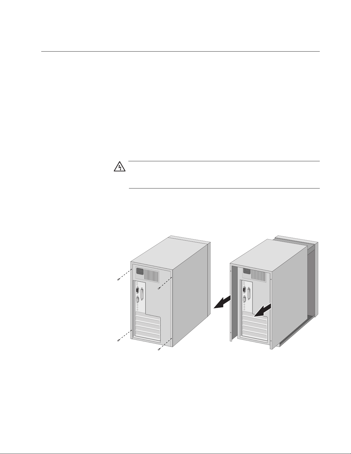
Warning
High voltage inside the system presents a safety hazard. Make sure
the power is off before removing the cover.
AT-29xx Series Gigabit Ethernet Adapters Installation Guide
2. Remove the system cover and select any appropriate empty PCI slot.
See Figure 4.
If you do not know how to identify an appropriate PCI slot, refer to your
system documentation.
Figure 4. Removing the PC Cover
25
Page 26

Chapter 2: Installing the Hardware
3. Select an empty, non-shared PCI slot and remove the faceplate.
Keep the faceplate in a safe place. You may need it for future use. See
Figure 5.
Figure 5. Removing the Faceplate From PCI Slot
Note
If you cannot locate or know how to find an appropriate PCI slot,
refer to the documentation that came with your system.
4. Remove the network adapter card from the shipping package and
store the packaging material in a safe location.
Caution
Wear a grounding device and observe electrostatic discharge
precautions when installing the network adapter card in a system.
Failure to observe this caution could result in damage to the card.
5. Applying even pressure at both corners of the card, push the adapter
card until it is firmly seated in the appropriate PCI slot.
26
Page 27

AT-29xx Series Gigabit Ethernet Adapters Installation Guide
Make sure the card is securely seated. See Figure 6.
Figure 6. Inserting the Network Adapter Card
Note
The connector dock in a 32-bit PCI slot is shorter than in a 64-bit PCI
slot. Although the AT-29xx series adapter is designed to fit in either
slot type, when installed in a 32-bit PCI slot, part of the adapter’s
connector edge remains undocked. This is part of normal operation.
Caution
Do not use excessive force when seating the card, because this may
damage the system or the adapter. If the card resists seating,
remove it from the system, realign it, and try again.
27
Page 28

Chapter 2: Installing the Hardware
6. Secure the network adapter card to the chassis with a Phillips-head
screw (not provided) as shown in Figure 7.
Figure 7. Securing the Adapter Card
7. Replace the system’s cover and secure it with the screws removed in
Step 2.
8. Disconnect any personal antistatic devices.
9. Power the system on.
Once the system returns to proper operation, the adapter hardware is fully
installed. Next, connect the network cables. See “Connecting the Network
Cables” on page 29.
28
Page 29

Connecting the Network Cables
All the fiber Gigabit Ethernet network adapters have two fiber optic
connectors for attaching the system to a compatible link partner, or an
IEEE 802.3z compliant gigabit switch. After connecting the system to the
network and power is supplied, the adapter performs auto-negotiation and
attempts to establish the connection at 1000 Mbps full-duplex only.
To connect a network cable to the adapter, perform the following
procedure:
1. Prepare a fiber optic cable according to the specifications in Table 4.
Table 4. 1000BASE-SX Fiber Optic Cable Specifications
AT-29xx Series Gigabit Ethernet Adapters Installation Guide
Port Type Connector Media
1000BASE-SX Fiber Optic 50 µm
multimode
1000BASE-SX Fiber Optic 62.5 µm
multimode
Warning
The fiber optic ports contain a Class 1 laser device. When the ports
are disconnected, always cover them with the provided plug.
Exposed ports may cause skin or eye damage.
2. Connect one end of the cable to the adapter.
3. Connect the other end of the cable to the appropriate Ethernet network
port or fiber optic port.
Note
After the cable is properly connected at both ends, the adapter port
LEDs should be functional. See “LEDs” on page 16 for a description
of LED operation for each adapter model. For driver installation and
configuration instructions, refer to the software configuration for a
specific driver.
Maximum
Distance
550 meters
(1,804 feet)
275 meters
(853 feet)
29
Page 30

Chapter 2: Installing the Hardware
30
Page 31

Appendix A
Specifications
Physical Specifications
Dimensions: AT-2916T : 11.99 cm x 5.29 cm (4.72 in. x 2.08 in.)
Weight: AT-2916T : 65 g (.14 lbs.)
Environmental Specifications
AT-2971T : 16.76 cm x 5.73 cm (6.6 in. x 2.26in.)
AT-2971SX : 16.76 cm x 6.44 cm (6.6 in. x 2.54 in.)
AT-2971T : 72 g (.16 lbs.)
AT-2971SX : 92 g (.20 lbs.)
Operating Temperature: 0°C to 50°C (+32°F to +122°F)
Storage Temperature: -20°C to +70°C (-4°F to +158°F)
Operating Humidity: 30% to 80% (noncondensing)
Storage Humidity: 10% to 95% (noncondensing)
Maximum Operating Altitude: 10,000
Maximum Storage Altitude 35,000 ft.
Power Specifications
Operating Voltage: 3.3V
Power Consumption: AT-2916T : 3.22 Watts, @ +3.3V
AT-2971T : 3 Watts, 0.9A @ +3.3V
AT-2971SX : 3 Watts, 0.9A @ +3.3V
31
Page 32

Appendix A: Specifications
Performance Specifications
PCI clock: 33/66 MHz max
PCI-X clock: 66 to 133 MHz
PCI or PCI-X Data/Address: AT-2916T 32-bit
Operating Specifications
Output Optical Power: -9.5 dBm minimum to -4 dBm maximum
Input Optical Power: -18 dBm to 0 dBm maximum
Receive Sensitivity: -12.5 dBm with 62.5 um fiber or
AT-2971T 32-bit and 64-bit
AT-2971SX 32-bit and 64-bit
-13.5 dBm with 50 um fiber
32
 Loading...