

Page 1

The GS1 is the only true 8 buss recording console at this price level. It is
sonically transparent and specifically designed for digital multitracking.
You will find this ultra compact console is outstanding as a professional
tool, designed and built on a well proven operating format using well
proven technology.
We have incorporated the latest in Mic pre-amp developments. We out
perform conventional designs and we have given the GS1 127dB EIN, a flat
transparent frequency response of 10Hz to 30kHz (+0/-1dB). The Mic
Input to Insert send (Direct out) is rated better than 300kHz (-1dB).
We hope you will enjoy using the GS1. Welcome to Allen & Heath.
Welcome to the GS1
i
3/5
0
10
to Aux 2 & 3
to Aux 4 & 5
Level
0
10
Level
0
10
Level
0
10
L
TAPE RTN
TAPE RTN
TAPE RTN
TA
R
PAN
L
R
PAN
L
R
PAN
L
R
PAN
L
R
PAN
L
R
PFL
PAN
L
R
PFL
PAN
L
R
PFL
PAN
L
R
PFL
PAN
L
R
PFL
PAN
L
R
A
34567
Channel
On
8
Channel
On
9/10
Channel
On
11/12
+10
+5
+10
0
+5
+10
0
+5
+10
-5
0
+5
+10
-5
0
+5
+10
-10
-5
0
+5
+10
Channel
Channel
On
L-R L-R
GS1
USER
GUIDE
GS1
USER
GUIDE
Page 2

Section 1 G
ETTINGSTARTED
Block Diagram
Connections
Section 2 S
IGNALPATHS
Mono Input and Stereo Input Paths
EQ
Aux
Monitor and Stereo Returns
PFL, Pan, Channel On and Routing
Meters and the Master Section
Section 3 U
SINGMUTEAUTOMATION
Mute Patches
Connections
Uses for Automation
Section 4 MIDI A
PPLICATIONS
MIDI Transport Control (MMC)
MIDI Commands
Section 5 G
ETTING THE BEST FROM THE
GS1
Level Matching
Earthing
Grouping and Patchbays
Section 6 S
PECIFICATIONS ANDOPTIONS
GS1 and Expander
Meterbridge and PSU
Connector Diagrams - Jacks, Phono’s & XLR’s
MIDI Implementation
Audio Specifications
CONTENTS
GS1
iii
PAGE PAGE
1
3
5
7
9
11
13
15
17
19
21
23
25
27
29
32
33
34
35
37
38
This product has been manufactured in the UK by Allen &
Heath Ltd and is warranted from defects in materials or
workmanship for a period of one year from the date of
purchase by the original owner.
To ensure the high level of performance and reliability
for which this equipment has been designed and manufactured, please read this User Guide before use.
In the event of failure notify and return the defective unit to
ALLEN &HEATH or its authorised agent as soon as possible
for repair under warranty subject to the following conditions:
1
2
3
4
5
The equipment has been installed and operated in accordance with this User Guide.
The equipment has not been subject to misuse either
intended or accidental, neglect, or alteration other than
described in this User Guide or the Service Manual, or
approved by ALLEN &HEATH.
Any necessary adjustment, alteration, or repair has been
made by ALLEN &HEATH or its authorised agent.
The defective unit is to be returned, carriage prepaid, to
ALLEN & HEATH or its authorised agent and proof of
purchase made available on request.
Units to be returned should be packed to avoid transit
damage and be accompanied by the Power Supply Unit.
These terms of warranty apply to UK sales. In other territories the terms may vary according to legal requirements.
Copyright © 1995 Allen & Heath Limited
All rights reserved
Publication AP2061 Issue 2
Information in this manual is subject to change without notice and
does not represent a commitment on the part of the vendor.
Allen & Heath Limited shall not be liable for any loss or damage whatsoever arising from the use of information or error contained in this
manual.
No part of this manual may be reproduced in any form without prior
permission from Allen & Heath Limited.
Allen & Heath Limited
Kernick Industrial Estate, Penryn, Cornwall, England TR10 9LU.
Tel : (44) 01326 372 070. Fax : (44) 01326 377 097
CONDITIONS OF WARRANTYLIMITED ONE YEAR WARRANTY
ii
Page 3
MICROPHONE
PHANTOM POWER
MIC/LINE XLR
2= +
LINE IN
LINE/XL
MI
H
M
L
3 BAND EQUALISER
INSERT TIP -
RING -
MIXDOWN
TAPE RTN IN
GAIN
LEVEL
2/4
3/5
1
PF
FADER
CHANNEL
ON
MUTE
PROCESSOR
1-2
3-4
5-6
7-8
L-R
AUX 1-
GRP 1-
LEF
RIGHT
PF
AUX 1 PRE
AUX 1 POST
AUX 2
AUX 4
AUX 5
AUX 3
MONO INPUT 1 OF 8
PAN
PAN
1-2
3-4
5-6
7-8
L-R
PAN
CHANNEL
ON
MUTE
PROCESSOR
2/4
3/5
1
AUX 1 PRE
AUX 1 POST
AUX 2
AUX 4
AUX 5
AUX 3
HF
2 BAND EQUALISER
LF
FADER
L
HI
GAIN
L/MONO
R
STEREO
INPUTS
PAN
LEVEL
L/MONO
R
STEREO
RETURNS
EXPANDER
STEREO INPUT 1 OF 4
PF
AUX 1-
GRP 1-
LEF
RIGHT
PF
1
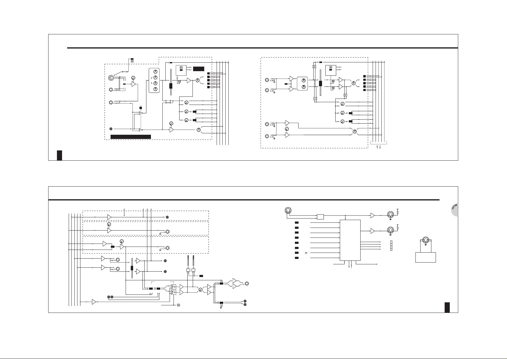
SECTION 1B BLOCK DIAGRAM - OUTPUTS AND MIDI
2
GS1
1
SECTION 1A BLOCK DIAGRAM - INPUTS
AUX 1-5
GRP 1-8
LEFT
RIGHT
PFL
GROUP (1-8) MIX
AUX (2-5) MIX
AUX 1 PRE MIX
AUX 1 POST MIX
LEFT MIX
RIGHT MIX
PFL MIX
CUE (PRE)
AUX (POST)
2 TRACK IN
EXPANDER METERBRIDGE
LEVEL
LEVEL
L INSERT
R INSERT
FADER
MIDI
GROUP (1-8) OUT
AUX (2-5) OUT
AUX 1 OUT
2 TRACK OUT
(MAIN OUT)
MONITOR
L-R
AUX1
2TRK
PFL DC
GROUP
1 OF 8
AUX 2-5
TIP = +
1 OF 4
AUX 1
TIP = +
MONITOR METER
L
R
L
LEVEL
LO
HI
CUE TO
HEADPHONES
MONITOR
OUTPUT
MUTE
HEADPHONES
L
R
MONITOR AMP
& SPEAKERS
L
R
LEVEL
R
PFL
ACTIVE
MATCH
MONITOR
MASTER
IN
MMC FUNCTION KEYS
DPTO-ISOLATOR
MODE
LEARN
SET LOC
F6
>>
FF
F5
<<
REW
F4
>
PLAY
F3
STOP
F2
LOCATE
F1
CHANNEL ON
SWITCHES
MUTE
PROCESSOR
EXPANDER
MUTE PROCESSOR
MIDI
THRU
MIDI
OUT
MMC
PATCH
MIDI
LEARN
CHANNEL ON
MUTES AND LEDS
ONLY USE ADAPTOR PROVIDED
AC 36V
POWER INPUT
PSU
POWER
Page 4
1
1
2
3
4
5
6
7
8
9
10
11
12
13
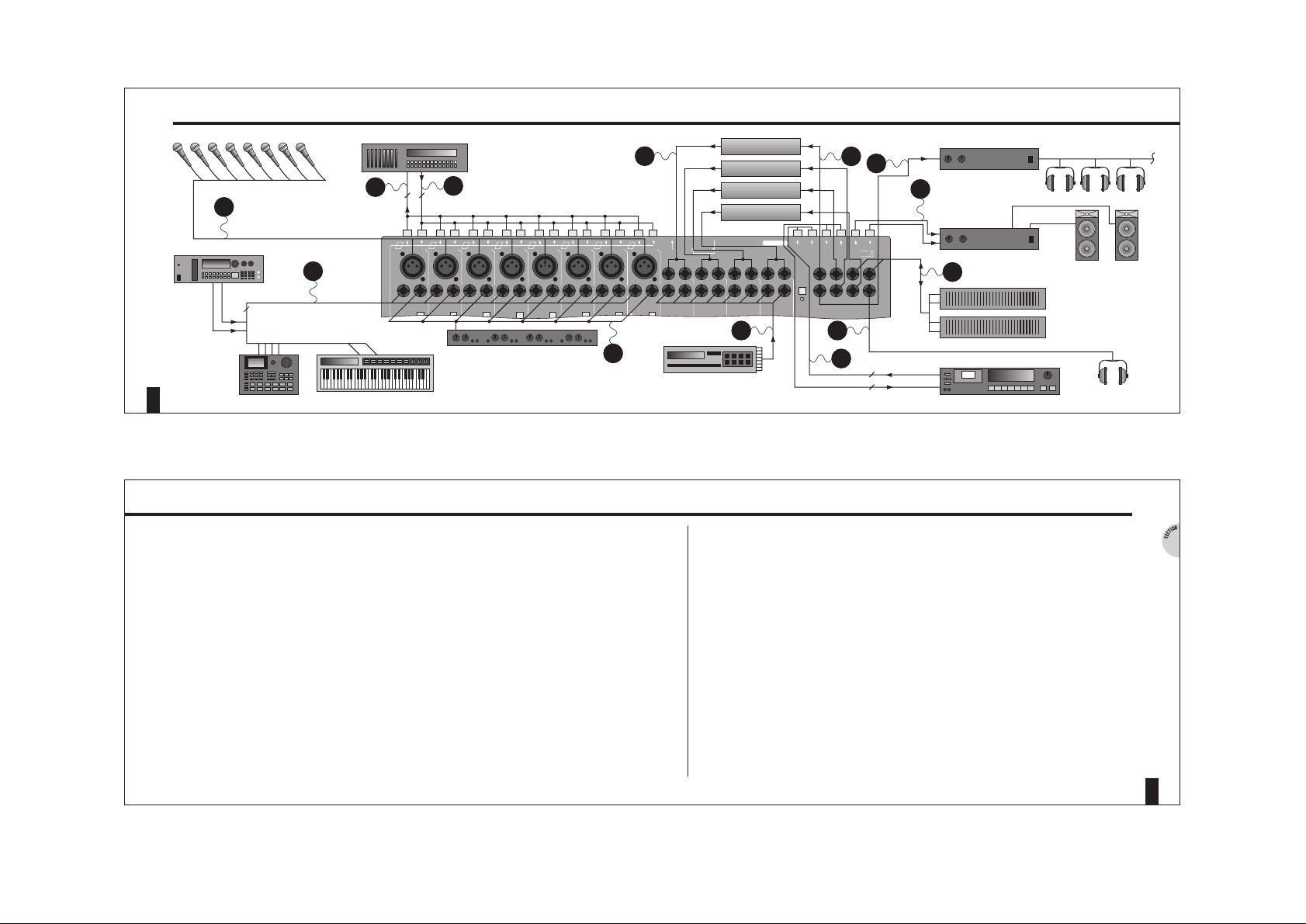
NOTES
Group outputs to Recorder.
Tape returns from Recorder.
Microphone inputs.
Line inputs from line devices.
Input stage inserts for gates, compressors and expanders etc.
Stereo line inputs from line devices.
Stereo Returns for FX devices.
Aux sends 2 to 5 to FX devices.
Aux 1 to cue amp and headphone mix.
L R inserts for compressors or EQ etc.
Engineer’s headphone monitor.
L R monitor O/P to monitor speaker amp and speakers.
L R mix to and from 2 track master recorder.
CONNECTIONS
4
GS1
3
SECTION 1 GETTING STARTED
'MIXdown'
Line Insert
1
Mic
Microphone
XLR / Line
1
GROUP
out
TAPE RTN
in
1
GROUP
out
Line Insert
2
Mic
Microphone
2
GROUP
out
TAPE RTNinGROUP
out
Microphone
3
GROUP
out
TAPE RTNinGROUP
out
Line Insert
3
Mic
Microphone
4
GROUP
out
TAPE RTNinGROUP
out
Line Insert
4
Mic
Microphone
5
GROUP
out
TAPE RTNinGROUP
out
Line Insert
5
Mic
Microphone
6
GROUP
out
TAPE RTNinGROUP
out
Line Insert
6
Mic
Microphone
7
GROUP
out
TAPE RTNinGROUP
out
Line Insert
7
Mic
Line Insert
8
Mic
Microphone
8
GROUP
out
TAPE RTNinGROUP
out
Microphone
Phantom Power
1
9/10
L/Mono R
Stereo Inputs
11/12
L/Mono R
Stereo Inputs
13/14
L/Mono R
Stereo Inputs
15/16
L/Mono R
Stereo Inputs
L/Mono R
Stereo Returns
L/Mono R
Stereo Returns
L/Mono R
Stereo Returns
2
AUXILIARY
out
27/28 29/30 31/3225/26
53 Headphones
4
L/Mono R
Stereo Returns
L
INSERT
R
SEND (tip)
RETURN (ring)
+6+6
MIDI
out
MIDI
thru'
MIDI
in
AC 36V
Power Input
Only use adaptor provided
Serial No.
Made in England by Allen & Heath Ltd
2 TRACKinL R 2 TRACK
out
(Main out)
L R Mon. Amp
& Speakers
LR
LR
Mic - XLR
XLR pad or
XLR / Line
XLR / Line
XLR / Line
XLR / Line
XLR / Line
XLR / LineXLR / Line
3123
12312312312312312
3
12
CUE AMP
R
COMPRESSOR,
GRAPHICS ETC.
L
SAMPLER
KEYBOARD
8 TRACK RECORDER
8 8
DAT
2
2
8
VOICE
GATES, COMPRESSORS, EXPANDERS
DRUM
MACHINE
7
3
2
1
STUDIO FX2
STUDIO FX1
STUDIO DELAY
STUDIO DELAY
8
6
12
9
STUDIO AMP
10
11
5
4
13
Page 5
1
2
3
4
M
ONO INPUT
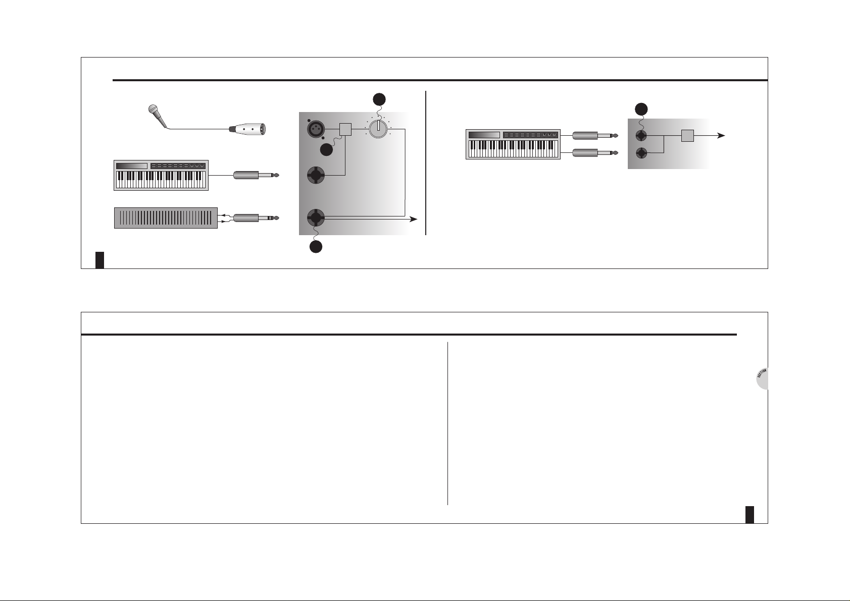
Main input gain control allows optimum settings of input signal. Set this level
using PFL and the Master Meters.
Use the Mic line switch to select the input source. When no input is connected to
the line socket this switch acts as a 30dB pad on the Mic input.
(See section 5)
The insert socket sends the input signal to an external device. This may be a gate,
compressor or de-esser. The signal returns to the same point in the channel path.
See the diagram in the connector section for correct wiring.
S
TEREO INPUT
If only the left input is used the signal appears on both left and right paths,
effectively mono.
MONO INPUT AND STEREO INPUT PATHS
6
2
GS1
NOTES
STEREO INPUT
L
R
MONO INPUT - MIC AND LINE CONNECTED
4
GAIN
1
MIC/LINE XLR
2
3
12
GAIN
LINE
INSERT
3
LO
HI
0
10
5
SECTION 2 SIGNAL PATHS
Page 6
1
2
C
HANNEL EQ
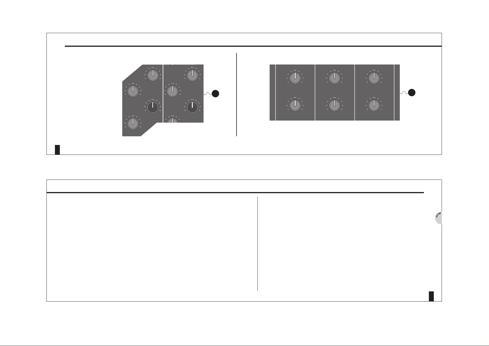
Each mono channel strip has a three band EQ. The mid sweep ranges from 300Hz
to 12KHz.
S
TEREO INPUT EQ
Each stereo input channel has a two band shelving EQ.
On each EQ the HF shelf starts at 12KHz. The LF shelf starts at 80Hz. Each level
control gives 14dB of cut and boost. A centre detent position makes it easy to find
the ‘off’ position.
EQ
8
2
GS1
NOTES
2
1
Equaliser
M Xdow
LF
-14 14
MF
sweep
300
HZ
12
kHz
MF
Gain
HF
-14 14
-14 14
0
10
Gain
0
10
LF
-14 14
MF
sweep
300
HZ
12
kHz
MF
-14 14
Equaliser
M Xdow
HF
-14 14
CHANNEL EQ STEREO INPUT EQ
7
SECTION 2 SIGNAL PATHS
-14
Equaliser
-14
14
HF
14
LF
-14
Equaliser
-14
14
HF
14
LF
-14
Equaliser
-14
14
HF
14
LF
Page 7
1
2
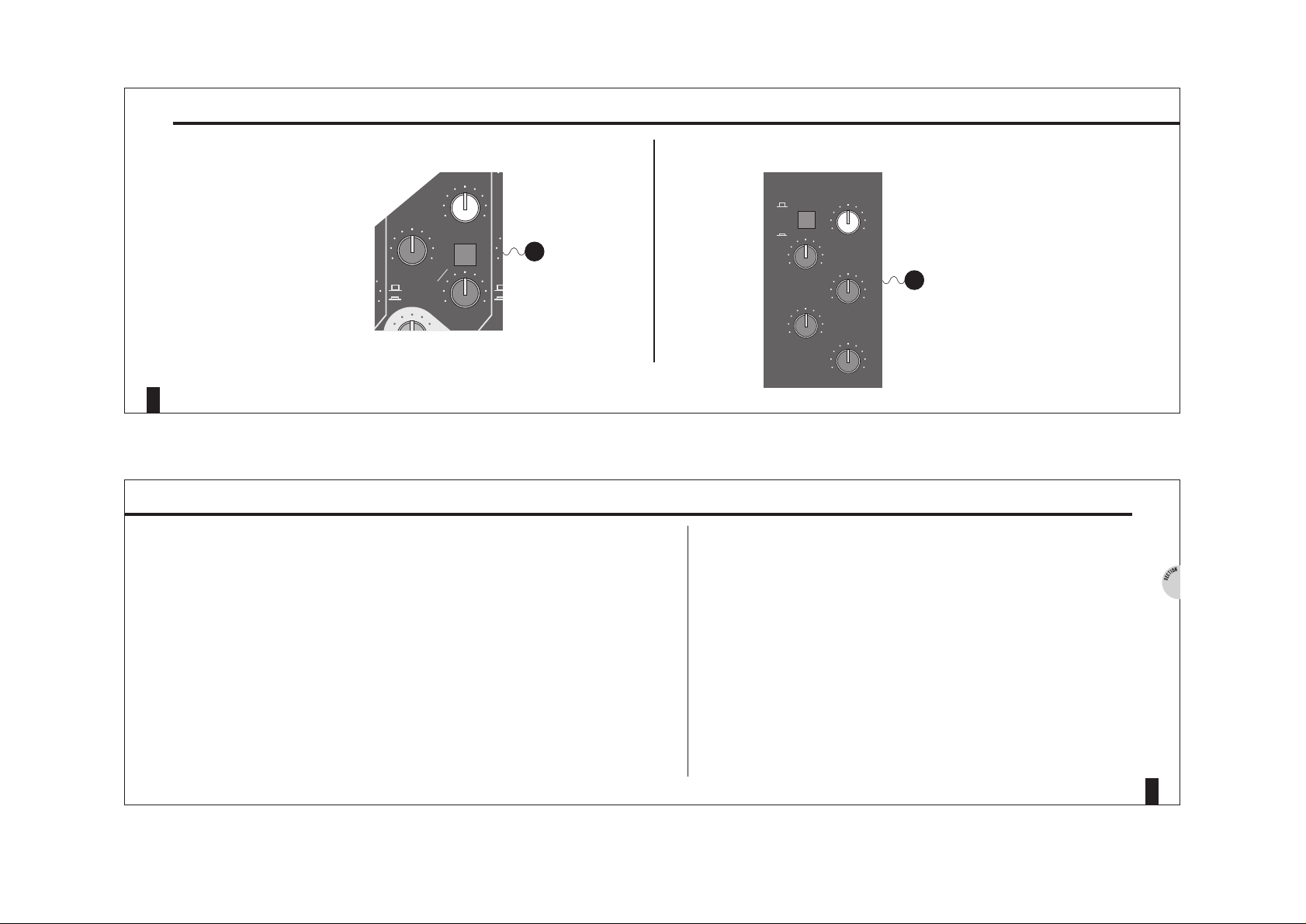
C
HANNEL AUX SENDS
There are five Aux busses on the GS1. These are typically used for sending
channel signals to common FX such as reverbs and delays. Auxs 2-5 are always
post fade. Aux sends 4 & 5 are accessed by pressing the Channel Aux send select
switch.
M
ASTER AUX SENDS
Aux 1 can be switched at the master section to be pre fade. A pre fade Aux is
commonly used for foldback or cue for a musicians headphone mix where the
monitor signal is not affected by channel fader. In most cases foldback will be
required from the tape returns, When Aux 1 is switched to pre, it selects the TAPE
RTN signal path from the mono channel strips.
AUX
10
2
GS1
NOTES
CHANNEL SENDS MASTER AUX SENDS
0
0
1
LF
-14 14
0
10
-14
Auxiliary Sends
0
10
0
3/5
0
10
to Aux 2 & 3
to Aux 4 & 5
2/4
1
2
9
SECTION 2 SIGNAL PATHS
Auxiliaries
AUX (post)
CUE (pre)
0
10
2
0
10
4
0
10
1
0
10
3
0
10
5
Page 8

2
1
2
NOTES
The Tape Return and Stereo Return inputs are provided to monitor the signals
coming back from a multitrack recorder and stereo effects devices.
MONITOR
The MIXDOWN switch flips the input signals to the alternate paths when mixing.
In this case the Mic/line input is available on the Tape Return path and the tape
return signal is available on the Channel path.
S
TEREO
If the left input is used on its own the signal is sent equally to both left and right
paths.
MONITOR AND STEREO RETURNS
12
GS1
STEREO RTN
L
R
LEVEL PAN
MIXDOWN
L
R
PAN
L
R
2
FROM
XLR/LINE
TO CHANNEL
PATH
0
10
0
10
LEVEL
0
10
0
10
L - OUT
R - OUT
1
MIC/LINE TO FADER
TAPE TO TAPE RTN.
TAPE TO FADER
MIC/LINE TO TAPE RTN.
1
1 OF 8
TAPE RTN
OUT
11
SECTION 2 SIGNAL PATHS
Page 9

1
2
3
4
5
6
PFL
The PFL switch is used for monitoring individual channel signals. Use PFL to set
the optimum channel level from the Mic/Line gain control or Hi/Lo switch. The PFL
active LED on the master section indicates when any PFL switch is active.
The level to the LR buss or groups (routing) is set using the main 100mm
channel fader. There is no need for group master levels as all routed channels can
easily be set for the optimum tape level.
The ‘Channel On’ switch mutes or unmutes the signal to the LR buss and groups.
This is a momentary switch and is controlled by the internal micro-processor and
via MIDI.
P
AN
Pan will route the signal proportionately to Left/(Odd) Right/(Even) group numbers.
R
OUTING
The routing matrix directs the channel signal to either the LR buss (through the LR
master fader to the 2 track out), or direct to the individual group output sockets.
The LR fader trims the overall mix level to the 2 track master outputs.
PFL, PAN, MUTE AND ROUTING
14
2
GS1
NOTES
PAN
CHANNEL
ON
PFL
CHANNEL PATH
STEREO INPUT
(2 TRACK OUT)
MAIN OUT
GROUP OUT
LR FADER
PFL
ACTIVE
8
FADER
1-2
3-4
5-6
7-8
1
2
3
PFL, PAN, CHANNEL ON (MUTE) & ROUTING
0
10
¥
-30
-20
-15
-10
-5
0
+5
+10
-5
0
+5
+10
4
L-R
5
6
PHONO
L IN
R IN
1 of 8
L
R
IN
13
SECTION 2 SIGNAL PATHS
Page 10

1
2
3
4
M
ETERS
The main output fader sets the level to the master 2 track recorder. The Hi/Lo
switch alters the meter sensitivity to enable correct level setting. The Hi setting is
for interfacing with professional equipment operating at +4dBu. Lo is for -10dBu
level operation.
M
ASTER SECTION
The Monitor Select switches allow the LR mix (Default), the 2 track return, or the
Aux 1 cue mix to be monitored through the speakers.
The speaker mute switch cuts the signal to the studio speakers. This enables the
musician/engineer to perform and to engineer in the same room using
Headphones.
Cue to headphones allows the LR mix to be monitored through the speakers, and
the Aux Cue buss through the headphones. This can be used as a monitor output
for the musician.
METERS AND MASTER SECTION
16
2
GS1
NOTES
LR FADER
MONITOR
LEVEL
MONITOR
OUTPUT
MUTU
CUE TO
HEADPHONES
L
R
MIX
BUSS
L
R
MONITOR AMP &
SPEAKERS
3
4
-5
0
+5
+10
MASTER SECTION
2 TRACK OUT
(MAIN OUT)
MONITOR SELECT
AUX 1
(CUE)
2 TRACK
LEVEL
MASTER
AUX 1
BUSS
2 TRACK
IN
= LR
= 2 TRACK
= AUX 1 (CUE)
2
HI/LO
1
METERS
15
SECTION 2 SIGNAL PATHS
Page 11

1
2
3
4
5
Patches are snap shots of mute settings.There are 6 available memories. To set
a mute patch do the following.
Using the Mode key, select the Patch LED.
Press the Learn key, the Learn LED will flash.
Set all ‘Channel On’ switches to the required settings.
Press the desired Function key to save the Patch. Press the Learn key to exit back
to Patch mode.
Whenever the Mode LED indicates Patch, each Function Key press will recall the
stored settings.
Note that Patches can be recalled using MIDI commands.
Recalling a Patch will also transmit a MIDI Program Change message.
Refer to section 6 for the MIDI implimentation.
MUTE PATCHES
18
3
GS1
NOTES
n
3
MODE KEY
c
5
LEARN KEY CHANNEL ON SAVE RECALL
c
1
c
c
2
4
17
SECTION 3 MUTE AUTOMATION
MMC
Patch
MIDI
Learn
Mode
Learn
Set Lo
F6
MMC
Patch
MIDI
Learn
Mode
Channel
On
Learn
Set Lo
F6
+5
0
nnel
Cha
n
O
-5
+5
0
Channel
On
-5
MMC
Patch
MIDI
Learn
MMC
Mode
Learn
Set Lo
F6
Patch
MIDI
Learn
Mode
Learn
Set Lo
F6
Page 12

1
2
3
1
2
3
AUTOMATION
The GS1 requires automation control from an external sequencer.
A MIDI Master keyboard and the GS1 will both require input to the sequencer. A
MIDI merge unit or a dedicated A/B switcher will be needed.
Just like a keyboard. The GS1 will transmit a MIDI message whenever a Channel
On switch is pressed. The GS1 will respond automatically when it receives this
message back from the sequencer.
N.B.
The Function Key mode does not affect the MIDI mute automation.
MIDI specifications are detailed at the end of this manual.
Some sequencers don’t ‘chase’ MIDI notes properly when starting from the
middle of a song. If this occurs, try recording Channel On patches at key points in
the song, such as choruses or verses.
CONNECTIONS
20
3
GS1
NOTES
THRU
OUT
MASTER KEYBOARD
3123123123123123123
12
3
12
GS1
3123123123123123123
12
3
12
GS1
Compact Studio Console
meterbridge
VOICES
VOICES
VOICES
THRU
THRU
IN
THRU
IN
IN
OTHER MIDI VOICES
& DEVICES
3
AUTOMATION CONNECTIONS
MIDI
MIDI
MIDI
THRU
MIDI
IN
MIDI OUT
IN
THRU
1
2
OUT
MIDI
IN
MERGE
19
SECTION 3 MUTE AUTOMATION
Page 13

1
2
3
P
ARALLEL CHANNELS
Use parallel channel connections to maximise tape usage. Each different sound
on the track can be mixed down several channels. Mute automation allows each
input to be processed separately. This avoids confusion in musicians headphones
and will result in better musical performances.
A
UTOMATED FX SENDS
Try out effects without having to commit to tape by using a paralell channel not
routed to the L R mix. The Aux send can then be automated using the Channel On
switch.
M
IXING
Clean up analogue tracks and stop noise from effects devices.
Automation allows hands free operation for other creative tasks such as performance and mix balance.
USES FOR AUTOMATION
22
3
GS1
NOTES
CHAN 1
CHAN 2
CHAN 3
1
2
ECHO
AUX 2
TRACK
OPEN
CLOSED
3
0
10
PARALLEL CHANNELS AUTOMATED FX SENDS MIXING
CHANNEL
ON
MUTE
TRK 4
21
SECTION 3 MUTE AUTOMATION
Page 14

1
2
3
4
5
T
APE MACHINES
Using the in built MIDI Machine Control the GS1 will directly control all MMC
compliant tape recorders.
Ensure MMC is selected using the Mode key. The Function keys are labelled
accordingly.
MIDI S
EQUENCERS
The GS1 can control the transport of many sequencers using it’s default MIDI
settings, see page 37.
A MIDI merge box is sometimes required for a complete MIDI set-up,
see page 20.
Ensure ‘MIDI’ is selected by using the Mode key.
TRANSPORT CONTROL (MMC)
24
4
GS1
NOTES
c
2
Mode
Learn
MMC
Set Loc
FF
F6
F5
Patch
MIDI
Learn
IN
3123123123123123123
12
3
12
GS1
3123123123123123123
12
3
12
GS1
Compact Studio Console
meterbridge
1
MIDI
OUT
3123123123123123123
12
3
12
GS1
3123123123123123123
12
3
12
GS1
Compact Studio Console
meterbridge
3
4
TAPE MACHINE MODE SELECT SEQUENCER MODE SELECT
IN
MIDI
OUT
MIDI
c
5
Mode
Learn
MMC
Set Loc
FF
F6
F5
Patch
MIDI
Learn
THRU
MIDI
23
SECTION 4 MIDI APPLICATIONS
Mode
Learn
Set Lo
F6
FF
Mode
Learn
Set Lo
F6
FF
Page 15

1
2
3
4
5
6
Learn MIDI commands in order to control external devices.
Select ‘MIDI’ using the Mode key, press the Learn key. The Learn LED will flash.
Press any Function Key to select which key should be used to store the MIDI
command.
Key Press
Transmit a MIDI message to the GS1 from a keyboard or any other device. This
message will be associated with a Function Key ‘press’.
Press the Function Key again.
Key Release
Transmit a second MIDI message for the Function key ‘release’.
After this the selected Function Key will transmit both ‘press’ and ‘release’
messages.
Press Learn Key to exit Learn Mode.
Note the GS1 must be in MIDI mode.
MIDI COMMANDS
26
4
GS1
NOTES
OUT
IN
3123123123123123123
12
3
12
GS1
3123123123123123123
12
3
12
GS1
Compact Studio Console
meterbridge
2
OUT
IN
3123123123123123123
12
3
12
GS1
3123123123123123123
12
3
12
GS1
Compact Studio Console
meterbridge
4
MODE SELECT MIDI MESSAGE (PRESS) LEARN MIDI MESSAGE (RELEASE) RECALL
c
51
Mode
Learn
MMC
Set Loc
FF
F6
F5
Patch
MIDI
Learn
Mode
Learn
MMC
Set Loc
FF
F6
F5
Patch
MIDI
Learn
Mode
Learn
MMC
Set Loc
FF
F6
F5
Patch
MIDI
Learn
2
Mode
Learn
MMC
Set Loc
FF
F6
F5
Patch
MIDI
Learn
Mode
Learn
MMC
Set Loc
FF
F6
F5
Patch
MIDI
Learn
25
SECTION 4 MIDI APPLICATIONS
Mode
Learn
Set Lo
F6
FF
Page 16

1
2
3
4
5
6
7
Matching the input level to the GS1 will result in the best audio performance.
If no Input is connected to the line socket then the Mic/line switch acts as a 30dB
pad on the Mic input.
To optimise the signal quality ensure the input level is as close to the console
meters’ ‘O’ operating level as possible.
The GS1 headroom.
The GS1 signal to noise ratio.
Use PFL to measure level on the master LR meters.
Aim for a 0dB to +3dB meter reading on average.
Check the multitrack recorder and the master 2 track recorder for specified
operating levels. Select either Hi (+4dBu ) or Lo (-10dBV) using the Hi/Lo switch
under the main LR meters.
LEVEL MATCHING
28
5
GS1
NOTES
3
GAIN
LINE/XLR
MIC
5
PFL
1
PAD
0
10
+6+6
+3+3
00
-3-3
-6-6
-10-10
-15-15
-20-20
LR
Hi
Lo
PFL
ACTIVE
LEVEL
MAX HEADROOM
NOISE FLOOR
6
4
2
CONSOLE 'O' OPERATING LEVEL
7
27
SECTION 5 GETTING THE BEST FROM THE GS1
Page 17

3123123123123123123
12
3
12
GS1
3123123123123123123
12
3
12
GS1
Compact Studio Console
meterbridge
STAR
POINT
EARTH
29
SECTION 5 GETTING THE BEST FROM THE GS1
1
2
For operator safety all equipment should be referenced to a good mains earth.
Multiple earth paths cause earth loops resulting in audible hum.
If earth loops cause problems disconnect the signal cable shields at
destination
end. Mic cable shields should remain connected at both ends.
Ensure all equipment goes directly to the common earth star point.
Note: Some audio equipment comes with an earth lift to disconnect audio earth
(OV) from chassis earth. Refer to the User Manuals for that equipment. This is
often used in rack mount devices.
WARNING: Never remove earth connections without checking for continuity to
ground.
EARTHING
30
5
GS1
NOTES
Page 18

7-8 7-8 7-8 7-8
PAN
GROUP
OUT
ODD
EVEN
1
2
GROUPING
34567
GROUP OUTPUTS (OUT OF GS1)
TAPE INPUTS (TAPE MACHINE INPUTS)
TAPE OUTPUTS (TAPE MACHINE OUTPUTS)
TAPE RETURNS (INPUTS TO GS1)
CHANNELS
PATCH BAY
}
}
NORMALED
NORMALED
PAN
PAN
PAN
1
2
3
G
ROUPING
Using groups allow different signals to be mixed independently down to one or
two tracks. For one track grouping turn the Pan either hard left (0dd) or hard right
(Even).
Routing switches assign the mix output to the selected multitrack inputs, either
1-8 on the GS1 or 9-16 on the expander.
P
ATCHBAYS
Patchbays allow total flexibility. The GS1 has been designed to remove much of
the need for a patchbay. However it may still be convenient to be able to patch
around external equipment to the GS1.
Note that all insert points should be normalised on a patchbay otherwise the
channel signal will be cut.
Choose a normalled patchbay for convenience: A normalled patchbay links all
relevant inputs and outputs so many patch leads are not required.
GROUPING AND PATCHBAYS
32
5
GS1
NOTES
31
SECTION 5 GETTING THE BEST FROM THE GS1
Page 19

3123123123123123123
12
3
12
GS1
3123123123123123123
12
3
12
OPTIONAL
EXPANDER
W
H
D
WEIGHT
315mm
59mm
496mm
5kg/11lb
GS1
W
H
D
WEIGHT
520mm
59mm
496mm
7.5kg/16.5lb
D
W
W
D
H
GS1
34
6
33
SECTION 6 SPECIFICATIONS AND OPTIONS
OPTIONAL
METERBRIDGE
W
500mm
H
D
Compact Studio Console
GS1
meterbridge
W
H
D
WEIGHT
175mm
22mm
1.5kg/3.3lb
D
PSU
W
108mm
H
60mm
D
77mm
WEIGHT
1kg/2.2lb
W
Page 20

MONO JACK
GRAPHIC
UNBALANCED JACK
TIP
RING
SLEEVE
INSERT JACK
SLEEVE RING
TIP
TIP
RING
SLEEVE
DIRECT OUT
FROM INSERT
SLEEVE TIP
LINK RING TO GND
1/4" JACKS RCA PHONO
SIGNAL GND
BALANCED JACK
SEND
LINK TO TIP
GND
SHIELD
SIGNAL
GND
-
GND
SLEEVE
RING
TIP
+
GND
GND
+
RING
:
:
:
SEND
RETURN
GND
:
:
:
GS1
36
6
35
SECTION 6 SPECIFICATIONS AND OPTIONS CONNECTOR DIAGRAMS
UNBALANCED
(SWITCH OFF PHANTOM POWER)
MALE PLUG WIRING VIEW
2
3
1
BALANCED
PIN 2 = +PHASE
PIN 3 = - PHASE
PIN 1 = OV
2
3
1
LINK PIN 3 TO PIN 1
3-PIN XLR PLUGS
1
3
2
GS1 MIC INPUT
IN
THRU OUT
MIDI
GS1 SOCKETS
1
3
2
FROM SOURCE
POWER INPUT SOCKET
18V AC18V AC
CENTRE TAP
Page 21

GS1
AUDIO SPECIFICATIONS
38
6
37
SECTION 6 SPECIFICATIONS AND OPTIONS MIDI IMPLEMENTATIONS
G#
A0
A#0
B0
C1
C#1
D1
D#1
E1
F1
F#1
G1
CH
1
2
3
4
5
6
7
8
9
10
11
12
DEC
32
33
34
35
36
37
38
39
40
41
42
43
HEX
20
21
22
23
24
25
26
27
28
29
2A
2B
BASIC GS1
HEX DEC CH
2C 44 13 G#1
2D 45 14 A1
2E 46 15 A#1
2F 47 16 B1
30 48 17 C2
30 49 18 C#2
32 50 19 D2
33 51 20 D#2
G#1
A1
A#1
B1
C2
C#2
D2
D#2
CH
13
14
15
16
17
18
19
20
DEC
44
45
46
47
48
49
50
51
HEX
2C
2D
2E
2F
30
30
32
33
TRANSMITTED NOTE
9n kk v1 kk v2
n - MIDI Channel (must be console’s channel)
kk - Note number (see table 1 & 2)
v1 => 40H Mute ON
<= 3FH Mute OFF
v2 = 0
RECEIVED NOTE
9n kk vv
n - MIDI channel = 16
kk - Note number (see table 1 & 2)
vv => 40H Mute ON
<= 3FH Mute OFF
= 0 IGNORED
PATCH RECALL
Cn p
where
n - MIDI channel = 16
p - Program Change Number
GS1 EXPANDER
F0, 7F, 7F, 06, 44, 02, 00, 08, F7
F0, 7F, 7F, 06, 01, F7
F0, 7F, 7F, 06, 02, F7
F0, 7F, 7F, 06, 05, F7
F0, 7F, 06, 04, F7
F0, 7F, 7F, 06, 4C, 02, 08, 01, F7
LOCATE
STOP
PLAY
REW
FWD
SET LOCATE
1
2
3
4
5
6
MMC MESSAGENAMEFKEY
CF 00
CF 01
CF 02
CF 03
CF 04
CF 05
1
2
3
4
5
6
PROG CHNG
MESSAGE
FKEY
NOTES
OUTPUTS
2 Track out Unbal. RCAPhono 50ohms
Group out Unbal. RCA Phono 50ohms
Aux. out Unbal. 1/4” Jack 50ohms
Inserts sends Unbal. 1/4” Jack - tip sends 50ohms
Monitor out Unbal. RCA Phono 50ohms
Phones out Unbal. tip left, ring right for 8-400ohms Headphones
PARAMETER
Max O/p Level +21dBu into 2k ohms
Meters Peak responding, 0VU=+4dBu or -10dBV as selected
Frequency Response 10Hz to 30kHz +0/ -1dB
Distortion - THD (Line to Mix out @ 1kHz) 0.006%
Crosstalk >75dB @ 1kHz
Noise - 22Hz to 22kHz MIC EIN -127dB into 150ohms
Noise - Pre-amp @ 0dB -88dBu
Noise - Mix -82dBu
INPUTS
Mic In Bal. pin 2 hot, 3 cold >2kohms var -60 to -20dBu
Line In Bal. pin 2 hot, 3 cold >25kohms var -30 to +10dBu
Line In Unbal. tip hot, ring gnd >25kohms var -30 to +10dBu
Stereo In Unbal. tip hot, ring gnd >10kohms +4dBu or -10dBV
Sereo Rtn Unbal. tip hot, ring gnd >5kohms +4dBu or -10dBV
2 Track Rtn Unbal. >10kohms +4dBu or -10dBV
Tape Return Unbal. >5kohms +4dBu or -10dBV
Insert Return Unbal. ring return >5kohms +4dBu or -10dBV
+4dBu, or -10dBV
Depending upon operating level
set +21dBu max.
Patch Mode
MMC Mode
9F 5D 20
9F 5F 20
9F 5E 20
9F 5B 20
9F 5C 20
9F 58 20
RECORD
STOP
PLAY
REW
FWD
CYCLE
1
2
3
4
5
6
MIDI MESS.
(PRESS)
NAMEFKEY
9F 5D 00
9F 5F 00
9F 5E 00
9F 5B 00
9F 5C 00
9F 58 00
A5
B5
A#5
G5
G#5
E5
MIDI MESS.
(RELEASE)
NOTE
MIDI Mode
Page 22

Allen & Heath, Kernick Industrial Estate, Penryn, Cornwall, TR10 9LU, England. Telephone : (44) 01326 372 070 Facsimile : (44) 01326 377 097
PUBLICATION AP2061 ISSUE 2
PRINTED IN ENGLAND ON PAPER FROM A SUBSTAINABLE WOODSTOCK. DESIGN BY INVOGRAPHIS
 Loading...