

Page 1

GS1
compact 8 buss console
SERVICE
MANUAL
PUBLICATION AP2064
Page 2

INTRODUCTION
The information presented in this manual is intended for competent technical personnel to carry out service and product
support for the GS1. We assume that the reader is familiar with the related electronic theory and audio terminology,
and is able to carry out basic servicing, fault-finding and repair of audio equipment of this type. Service personnel should
also be familiar with audio systems, mains earthing and power requirements, as well as handling precautions.
For further information on the operation and application of the GS1, please refer to the USER GUIDE publication
AP2061 supplied with each unit.
Whilst we believe the information in this manual to be reliable we do not assume responsibility for inaccuracies. We
also reserve the right to make changes in the interest of further product development.
SERVICE AND TECHNICAL SUPPORT
Under normal conditions the GS1 does not require user maintenance or internal calibration. Any service work required
should be carried out by qualified technical personnel only.
We are able to offer further product support through our worldwide distribution network. To help us provide the most
efficient service please would you quote the console serial number in any communication regarding this product.
SAFETY WARNING !
Mains electricity is dangerous and can kill. Mains voltage is not present within the
GS1
console but is present in the external power supply unit. Do not attempt to disassemble the
power supply unit. Do not carry out any work within the
GS1
console while it is powered. The
external power supply unit is factory set to match your local a.c. mains supply and marked
on the cover. Check that this matches your local mains supply. Check your mains wiring
and earthing before switching on.
CONTENTS
INTRODUCTION ................................................................................... 2
SERVICE & TECHNICAL SUPPORT.................................................... 2
PRECAUTIONS ..................................................................................... 2
DIMENSIONS ........................................................................................ 3
CONNECTIONS .................................................................................... 3
TECHNICAL SPECIFICATION .............................................................. 4
MIDI IMPLEMENTATION DATA ........................................................... 4
CONSOLE FUNCTIONAL CHECK ....................................................... 5
CONSOLE DISASSEMBLY................................................................... 7
REMOVING THE CONSOLE CIRCUIT BOARD .................................. 8
EXPANDER DISASSEMBLY................................................................. 9
REMOVING THE EXPANDER CIRCUIT BOARD ................................ 1 0
EXPANDER OPTION FITTING INSTRUCTIONS................................. 11
METERBRIDGE OPTION FITTING INSTRUCTIONS .......................... 12
ORDERING SPARE PARTS ................................................................. 1 6
BLOCK DIAGRAM.................................................................................
GS1 CONSOLE CIRCUIT DIAGRAM PCB KEY ..................................
PCB COMPONENT LAYOUT - CHANS 1 to 8 .....................................
PCB COMPONENT LAYOUT - CHANS 9 to 16 & MASTER L-R.........
CONSOLE CIRCUIT DIAGRAMS (8 pages).........................................
GS1 EXPANDER CIRCUIT DIAGRAM PCB KEY ................................
EXPANDER PCB COMPONENT LAYOUT...........................................
EXPANDER CIRCUIT DIAGRAMS (3 pages).......................................
METERBRIDGE PCB LAYOUT .............................................................
METERBRIDGE CIRCUIT DIAGRAM...................................................
copyright © 1995 ALLEN & HEATH Ltd. All rights reserved
ALLEN & HEATH
TECHNICAL DIAGRAMS
Publication ......................AP2064 Issue 1
2 S1SM1
Page 3
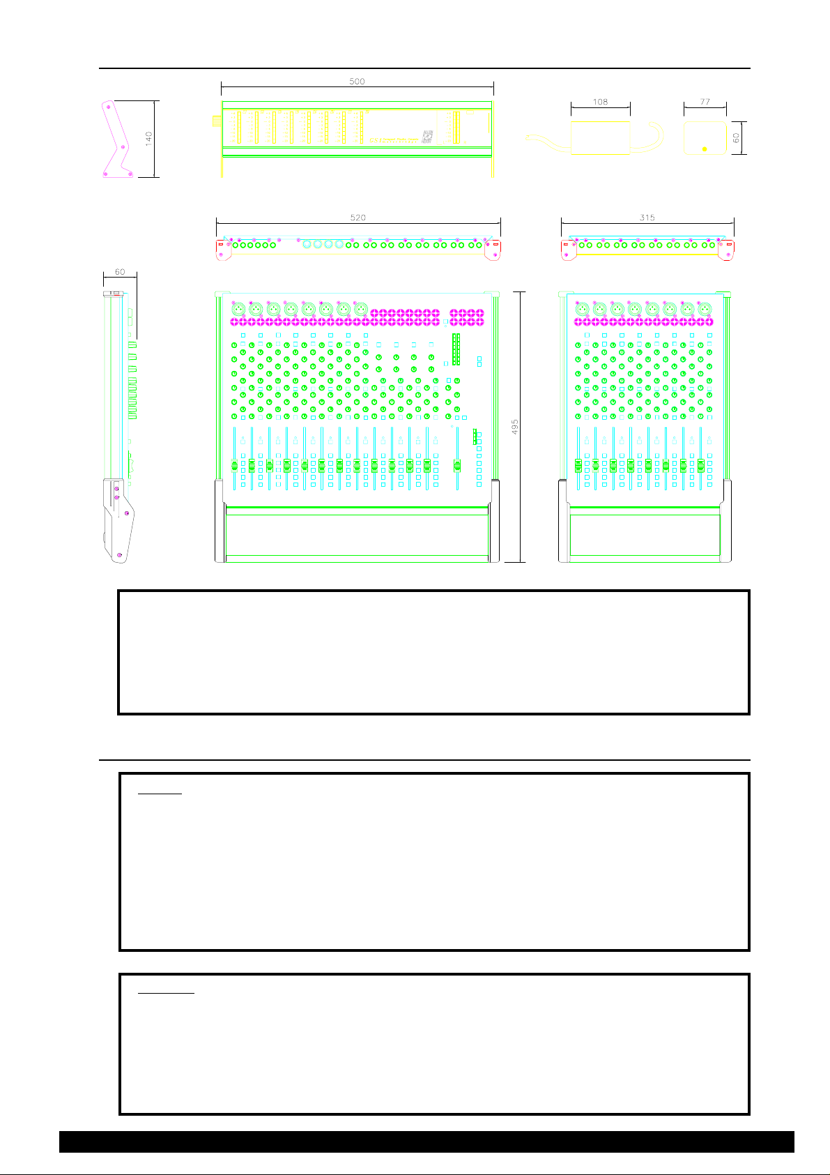
DIMENSIONS
PSU
METERBRIDGE
GS1
EXPANDER
Dimensions packed unpacked packed
W D H Kg(lb) Kg (lb)
GS1.................................................................... 63 0 ..... 550 ..... 140 ..................7.5 (16.5) ......................10.5 (23.1)
EXPANDER ....................................................... 400..... 550 ..... 140 .................. 5 (11) ............................7 (15.4)
METERBRIDGE ................................................ 630 ..... 100..... 140 .................. 1.5 (3.3) ........................2.5 (5.5)
PSU.................................................................... packed with GS1 ....................... 1 (2.2) ...........................packed with GS1
CONNECTIONS
INPUTS:
MIC IN ............................XLR............................ pin 2 hot, 3 cold balanced .......... >2k ohms .........variable -60 to -20dBu
LINE IN .......................... XLR............................ pin 2 hot, 3 cold balanced .......... >25k ohms .......variable -30 to +10dBu
LINE IN .......................... 1/4" JACK .................. tip hot, ring gnd unbalanced ...... >25k ohms ....... variable -30 to +10dBu
STEREO LINE IN........... 1/4" JACKS ................ tip hot, ring gnd unbalanced....... >10k ohms ....................-10dBV, +4dBu
STEREO RETURN ........1/4" JACKS................ tip hot, ring gnd unbalanced....... >5k ohms ......................-10dBV, +4dBu
2 TRACK RETURN ........RCA PHONO............. tip hot, sleeve gnd unbalanced .. >10k ohms....................-10dBV, +4dBu
TAPE RETURN .............RCA PHONO............. tip hot, sleeve gnd unbalanced .. >5k ohms ......................-10dBV, +4dBu
INSERT RETURN ..........1/4" JACKS................ tip send, ring return unbalanced >5k ohms ......................-10dBV, +4dBu
OUTPUTS:
2 TRACK OUT ...............RCA PHONO............. tip hot, sleeve gnd unbalanced.. 50 ohms ........................-10dBV, +4dBu
GROUP OUT .................RCA PHONO............. tip hot, sleeve gnd unbalanced.. 50 ohms ........................-10dBV, +4dBu
AUX OUT .......................1/4" JACKS................ tip hot, ring gnd unbalanced....... 50 ohms ........................-10dBV, +4dBu
INSERT SEND ...............1/4" JACKS................ tip send, ring return unbalanced 50 ohms........................-10dBV, +4dBu
MONITOR OUT .............RCA PHONO............. tip hot, sleeve gnd unbalanced..50 ohms........................-10dBV, +4dBu
HEADPHONE ................ 1/4" JACK .................. tip L, ring R ................................ for stereo headphones 8 to 400 ohms
3S1SM1
ALLEN & HEATH
Page 4
TECHNICAL SPECIFICA TION
0 dBu = 0.775 Volts RMS
0 dBV = 1 Volt RMS
Line level options: +4dBu (high level), -10dBV (low level)
MAX OUTPUTS: .......................... unbalanced +21 dBu 2kohms max load
FREQUENCY RESPONSE: 10Hz to 30kHz +0/-1dB
METERS: ..................................... 8 segment bargraphs for L,R
-20VU to +6VU (peak)
0VU = +4dBu or -10dBV as selected
POWER REQUIREMENTS: ........ 33VA max. at 50/60Hz
External power supply with Mains input factory set for local requirements.
Output supply on 5pin 240deg DIN 33Vac at 900mA
PHANTOM POWER: ................... +48V DC at 45mA generated internally
Global +48V ON switch with individual channel disable links.
CONSTRUCTION:....................... All metal chassis with aluminium extrusions on front and sides. Moulded plastic end caps.
DISTORTION: THD 0.006% Line in to mix out at 1kHz
CROSSTALK: Interchannel better than -75 dB at 1kHz
NOISE:............ 22Hz to 22kHz
MIC EIN -127 dB into 150 ohms
LINE pre-amp at 0dB -88 dBu
MIX noise -82 dBu
MIDI SPECIFICATION
Basic GS1 Implementation table
MUTE MIDI HEX D EC
CHANNEL NOTE
1 ...................... G#0..................... 20 ................ 32
2 ...................... A0 ....................... 21 ................ 33
3 ...................... A#0 ..................... 22 ................ 34
4 ...................... B0 ....................... 23 ................ 35
5 ...................... C1....................... 24................ 36
6 ...................... C#1..................... 25................ 37
7 ...................... D1....................... 26................ 38
8 ...................... D#1..................... 27................ 39
9 ...................... E1 ....................... 28 ................ 40
10 .................... F1 ....................... 29................ 41
11 .................... F#1 ..................... 2A ............... 42
12 .................... G1 ...................... 2B ............... 43
Transmitted Note
The following message is transmitted for a mute key press:
9n kk v1 kk v2
n ...................... - MIDI channel 16 (fixed)
kk .................... - Note number (see Implementation tables)
v1 .................... = 40H or more ..... Mute ON
........................ = 3FH or less ...... Mute OFF
v2 ....................= 0
Received Note
9n kk vv
n ...................... - MIDI channel (must be equal to 16)
kk .................... - Note number (see Implementation tables)
v v..................... = 40H or more ..... Mute ON
........................ = 3FH or less ...... Mute OFF
........................ = 0 ...................... IGNORED
GS1 Expander Implementation table
MUTE MIDI HEX D EC
CHANNEL NOTE
EX 1 ................ G#1..................... 2C ............... 44
EX 2 ................ A1 ....................... 2D ............... 45
EX 3 ................ A#1 ..................... 2E ............... 46
EX 4 ................ B1 ....................... 2F ............... 47
EX 5 ................ C2....................... 30................ 48
EX 6 ................ C#2..................... 31................ 49
EX 7 ................ D2....................... 32................ 50
EX 8 ................ D#2..................... 33................ 51
Function keys in Patch mode
Fkey Prog Change Message
1 ................................................... CF 00
2 ................................................... CF 01
3 ................................................... CF 02
4 ................................................... CF 03
5 ................................................... CF 04
6 ................................................... CF 05
Program Changes
In Patch mode, pressing a function key will transmit MIDI Program
Change messages as follows:
Cn p where,
n ...................... - MIDI channel = 16
p ...................... - Program Change No.
The console will also recall its stored Patches on receipt of the
above message in any mode
Function keys in MMC mode
FKey Name MMC Message
1 ...................... LOCATE............. F0, 7F, 7F, 06, 44, 02, 00, 08, F7
2 ...................... STOP ................. F0, 7F, 7F, 06, 01, F7
3 ......................PLAY .................. F0, 7F, 7F, 06, 02, F7
4 ...................... REW ................... F0, 7F, 7F, 06, 04, F7
5 ...................... FWD ................... F0, 7F, 7F, 06, 05, F7
6 ...................... SET LOCATE..... F0, 7F, 7F, 06, 4C, 02, 08, 01, F7
Function keys in MIDI mode
FKey Name MIDI Mess. (Press) MIDI Mess. (Release)
(see table Function keys in Patch mode)
1 ...................... RECORD............ 9F 5D 20 ............................... 9F 5D 00
2 ...................... STOP ................. 9F 5F 20 ............................... 9F 5F 00
3 ...................... PLAY .................. 9F 5E 20 ............................... 9F 5E 00
4 ...................... REW................... 9F 5B 20 ............................... 9F 5B 00
5 ...................... FWD................... 9F 5C 20 ............................... 9F 5C 00
6 ...................... CYCLE ............... 9F 58 20................................ 9F 58 00
ALLEN & HEATH
4 S1SM1
Page 5

CONSOLE FUNCTIONAL CHECK
The GS1 undergoes several rigorous stages of testing and quality control before being despatched from the factory. The
following procedure is offered to the distributor, dealer and customer to confirm that the unit has arrived without damage
and in full working order.
1. Packing inspection
1.1 Check that the packed unit is intact and has not suffered unreasonable transit damage.
1.2 Carefully open the box and check the contents: GS1 console in polythene bag, power unit, User Manual,
Brochure, and orange Quality assurance card.
2. Cosmetic inspection
2.1 Carefully unpack the unit and check general cosmetic quality. Check that the plastic end caps and front
armrest are securely attached.
2.2 Set the controls ready for the electrical tests which follow: All faders down, Gains min, EQ mid, Aux
min, Level min, Pan mid, switches up.
3. Power-up and initial LED test
3.1 Check that the power unit is marked with the correct mains voltage. Plug the power unit DIN connector
into the GS1 AC 36V socket. Plug the power unit mains connector into the local mains outlet.
3.2 Apply mains power. Check that the MMC LED to the left of the mode switch lights. Press the MODE
switch and check that the MMC, PATCH and MIDI LEDs light in turn.
3.3 Press each CHANNEL ON switch in turn lighting the green ON LED. Press again to turn the channel
off.
3.4 Press each PFL switch and check that the red PFL ACTIVE LED lights in each case.
3.5 Press the Microphone PHANTOM POWER switch checking that the red PHANTOM POWER LED
lights. Measure +48V nominal between pin 3 (+ve) and pin 1 (-ve) and between pin 2 (+ve) and pin 1
of each mic XLR.
4. Patch Learn check
4.1 Press the MODE switch to select Patch mode. Press the LEARN switch. The LEARN LED should flash.
4.2 Turn all channels ON. Press MMC Function Key F1. Now press LEARN again. The Learn LED should
go out.
This has stored a patch with all channels on which is recalled by pressing function key F1.
4.3 Turn all channels off. Test that pressing F1 turns all channels on.
4.4 Remove power from the GS1. Wait about 30 seconds and power on again. Select Patch mode and check
that the patch F1 has been ‘remembered’ with power removed.
5. Signal test
The following tests check the audio inputs and outputs for signal flow and quality. This does not test every
routing combination but does check that all circuit blocks and input/output connections are working.
The equipment suggested includes a CD player with known good quality music or test signal material,
and a stereo amplifier with high quality loudspeakers. Where further technical equipment is available,
more accurate and comprehensive testing is possible using a sinewave signal source, dB voltmeter and
oscilloscope. This requires the necessary level of technical competence.
5.1 Plug CD player left output into TAPE RTN on Channel 1. Start CD playing and raise L-R fader to ‘0’,
and raise Channel 1 TAPE RTN Level pot until the L, R meters both read an average ‘0’ (first red LED).
Press the meters Lo switch to check that the meter reading decreases to average around ‘-10’.
5.2 Connect the GS1 2-TRACK outputs to the amplifier/speaker system. Listen for music quality equally
out of the L and R speakers. Test the operation of the TAPE RTN Level and Pan pots.
Replug and repeat for Channels 2 to 8.
5.3 Plug CD into Channel 1 Mic XLR. Press Line/XLR (pad) switch. Raise channel Fader to ‘0’ and press
L-R. Adjust Gain for average ‘0’ meter reading. Listen to music quality. Test Fader, EQ, Pan and
Channel On functions.
5S1SM1
ALLEN & HEATH
Page 6

Replug and repeat for Channels 2 to 8.
5.4 Plug CD L and R into Channel 9/10 STEREO RTN jack sockets. Raise and test the RTN Level and Pan
pots.
Replug and repeat for Channels 11/12 to 15/16.
5.5 Plug CD L and R into Channel 9/10 Stereo Input jack sockets. Raise channel Fader to ‘0’ and press LR. Test Fader, Hi/Lo switch, EQ, Pan and Channel On functions.
5.6 Plug CD into Channel 1 Line input jack socket. Raise Fader to ‘0’, route to 1-2. Link GROUP Out 1
phono socket to TAPE RTN In phono socket. Raise TAPE RTN Level and listen to music quality. This
tests the channel routing to Group 1 out (listened to via TAPE RTN).
Test Channel 1 routing to all the groups by replugging the phonos.
5.7 Plug the amplifier into AUX Out 1. Use Channel 1 Aux send 1 to test the Aux output with the AUX master
pot raised to maximum.
Replug the amplifier and test AUX 2 to 5 outputs.
5.8 Replug the amplifier into the Mon Amp L and R outputs, raise the Monitor Level pot and Listen to the
Channel 1 Line input routed to L-R. Press Channel 2 PFL. The signal should be cut off. Set Channel
1 Fader to minimum and press Channel 1 PFL. The signal should reappear.
Replug the CD and test the PFL function of all the channels.
5.9 Plug CD into 2-TRACK In L and R. Press the 2-TRACK monitor switch and check music quality.
5.10 Press the Monitor Output Mute switch. The signal should be muted. Plug a pair of stereo headphones
into the GS1 Headphones jack socket and check signal quality.
6. Noise test
Remove the test signal source. The following tests listen to the residual noise generated by the GS1
electronics. This is well below the normal signal level of the console and represents the impressive signalto-noise performance of the GS1.
With the amplifier gain turned up listen to the noise under the conditions set out below.
WARNING: Because of the high amplifier gain required avoid switching signals to the outputs
while listening to noise. Always turn the amplifier down when replugging the output connectors.
Listen for a smooth residual hiss (white noise). Slight hum may be present on certain outputs but this
should be well within the hiss. Excessive hum, buzzing, clicks and popping may represent a problem.
6.1 Mon Amp output, all faders down, channel Gains min. Press each channel PFL in turn listening for
channel stage noise.
6.2 Channel Gains max. Press each PFL. Listen for channel preamp noise.
6.3 Replug amplifier to 2-TRACK Out L and R. Listen to noise with L-R fader down.
6.4 Raise L-R fader to maximum, all channel faders down, no channels routed.
6.5 Route all channels to L-R, raise faders to maximum. Switch each Channel On in turn.
6.6 Replug the amplifier to each GROUP and AUX output in turn listening for residual noise quality. Do this
with no groups routed, all channel AUX send pots down, and master AUX send pots maximum.
This completes the test.
Check that the unit is clean, controls reset with faders at maximum (as required for packing). Repack carefully in the
original packing complete with accessories.
Complete the service log with serial number and test details. Inform A&H immediately if any quality problem is noted.
ALLEN & HEATH
6 S1SM1
Page 7
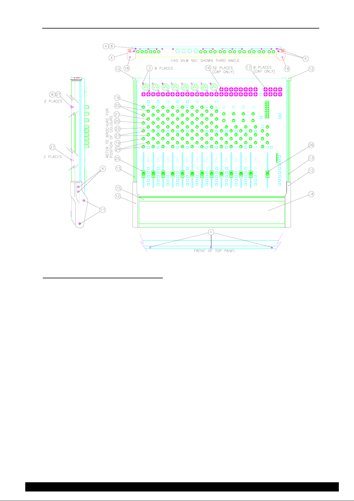
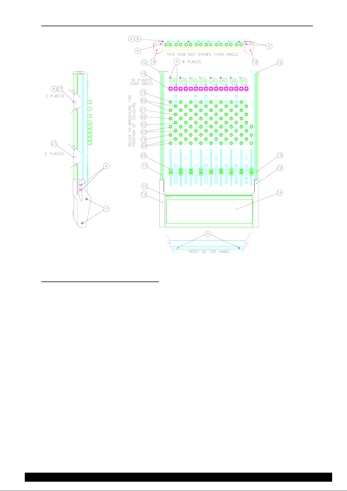
CONSOLE DISASSEMBLY
rear view
side view
Figure 1.
Stage 1 - Removing the front panel.
Refer to figure 1.
1. Remove the 4x screws (27) and 2 shakeproof washers (8) from the underside of the side extrusions. (13)
2. Remove the 4x screws (4) from the front end caps. (12)
3. Remove the front extrusion (15) with the plastic front end caps (12) still attached.
4. Remove the 2x screws (4) that attach the rear end caps (12) to the console chassis.
5. Remove the side extrusions (13) with the end caps (12) still attached by sliding them to the rear.
6. Remove the 13x fader knobs (25) and (26).
7. Remove the 126x rotary knobs. (19), (20), (21), (22), (23), (24)
8. Remove the 16x screws (3) from XLR connectors.
9. Using a suitable coin remove the 40x plastic jack nuts (16) & (17) by rotating the nut 45 degrees counterclockwise.
10. Working from the rear of the unit remove the 2x screws (4) and 1 shakeproof washer (8) that attach the
top panel to the base.
11. Working from the front of the unit remove the 3x screws (4) that attach the top panel to the base.
12. You can now lift the top panel off.
Re-assembly is the reverse of the above procedure, taking care to ensure that LEDs and switch caps fit through the top
panel correctly.
7S1SM1
ALLEN & HEATH
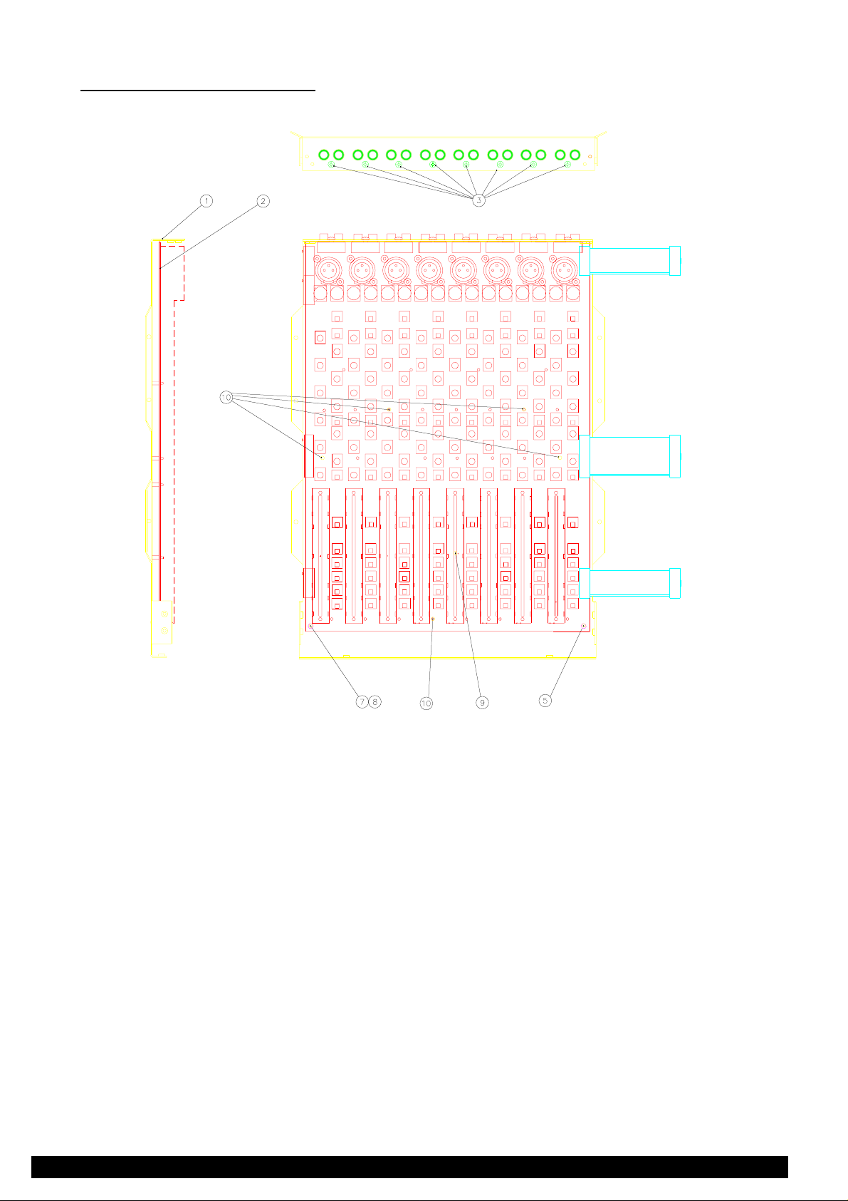
Page 8
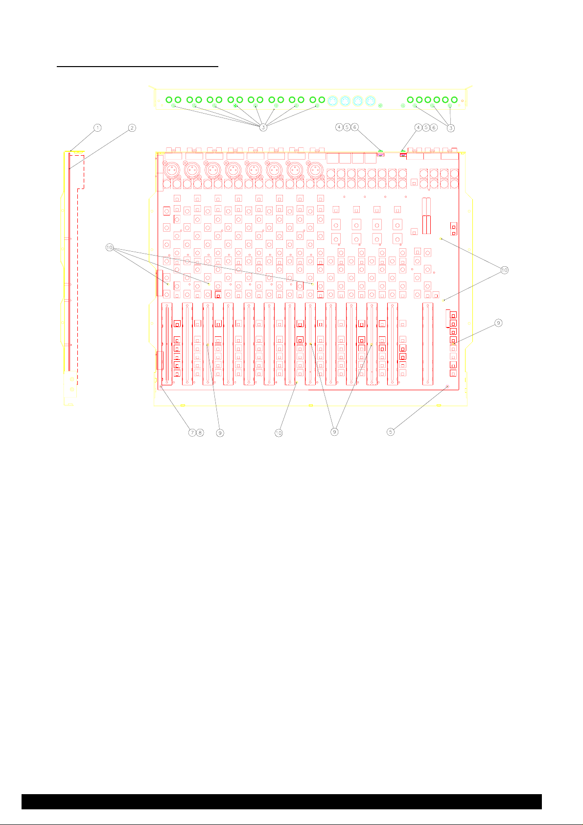
Stage 2 - Removing the PCB.
rear view
side view
Figure 2.
Refer to figure 2.
1. Remove the 2x screws (4), the 2 locknuts (5) and the 2 plastic insulators (6) that attach the regulators to
the rear panel.
2. Remove the 11x screws (3) from the phono connectors along the rear panel.
3. Remove the locknut (5) from front right stud.
4. Remove the nut (7) and shakeproof washer (8) from front left stud.
5. Carefully ease the PCB off the 6 plastic snap-in supports (10) by squeezing together top of supports with
pliers or suitable tool.
Re-assembly is the reverse of the above procedure taking care to:
a) Push the PCB down over all of the plastic snap-in supports.
b) Insulate the regulators from chassis base as follows:
1. Fit the grey insulator pads between the regulator and rear panel ensuring correct alignment with
the regulator and with hole in rear panel
ALLEN & HEATH
2. Insert the black plastic insulator into the hole of the regulator and the hole in the grey insulator
pad and rear panel
3. Push the screw through the black plastic insulator from the rear panel
4. Fix locknut on to the screw from the regulator side
8 S1SM1
Page 9
EXPANDER DISASSEMBLY
rear view
side view
Figure 3.
Stage 1 - Removing the front panel.
Refer to figure 3.
1. Remove the 4x screws (27) and 2 shakeproof washers (8) from the underside of the side extrusions. (13)
2. Remove the 4x screws (4) from the front end caps. (12)
3. Remove the front extrusion (15) with the plastic front end caps (12) still attached.
4. Remove the 2x screws (4) that attach the rear end caps (12) to the console chassis.
5. Remove the side extrusions (13) with the end caps (12) still attached by sliding them to the rear.
6. Remove the 8x fader knobs. (25)
7. Remove the 88x rotary knobs. (19), (20), (21), (22), (23), (24).
8. Remove 16x screws (3) from XLR connectors.
9. Using a suitable coin remove the 16x plastic jack nuts (16) by rotating the nut 45 degrees counterclockwise.
10. Working from the rear of the unit remove the 2x screws (4) and 1 shakeproof washer (8) that attach the
top panel to base.
11. Working from the front of the unit remove the 2x screws (4) that attach the top panel to the base.
12. You can now lift the top panel off.
Re-assembly is the reverse of the above procedure, taking care to ensure that LEDs and switch caps fit through the top
panel correctly.
9S1SM1
ALLEN & HEATH
Page 10
Stage 2 - Removing the PCB.
rear view
side view
Figure 4.
Refer to figure 4.
1. Remove the 8x screws (3) from the phono connectors along the rear panel.
2. Remove the locknut (5) from the front right stud.
3. Remove the nut (7) and shakeproof washer (8) from the front left stud.
4. Carefully ease the PCB off the 6 plastic snap-in supports (10) by squeezing together top of supports with
pliers or suitable tool.
Re-assembly is the reverse of the above procedure taking care to push PCB down over all plastic snap-in supports.
ALLEN & HEATH
10 S1SM1
Page 11
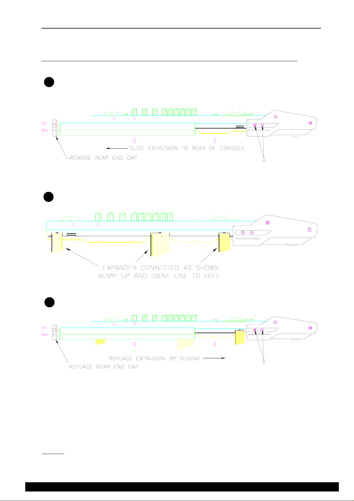
EXPANDER OPTION FITTING INSTRUCTIONS
The GS1 Expander Unit adds a further 8 channel strips giving 16 extra inputs.
Please read the following instructions carefully before attempting to fit the Expander.
Disconnect GS1 from Power Supply Unit and cables before fitting expander
Remove screws from left hand extrusion and rear end cap of GS1 and slide out extrusion as shown.
1
It may be necessary to loosen screws "A" to enable extrusion to slide.
1
Connect expander ribbon cables to the GS1 as shown. Note that the rear ribbon cable fits to the outside connector.
2
The adjacent connector is for the optional Meterbridge.
Replace extrusion and rear end cap taking care not to trap the ribbon cables.
3
TESTING THE EXPANDER
After connection of the expander reconnect the PSU and carry out the following checks.
Press Channel On switches on expander and check corresponding LED's light and extinguish on alternate presses.
Connect inputs to expander and check that they can be routed to Left, Right and Group outputs as required.
NOTE.
Take care not to strain the ribbon cables when moving the expanded Console.
11S1SM1
ALLEN & HEATH
Page 12
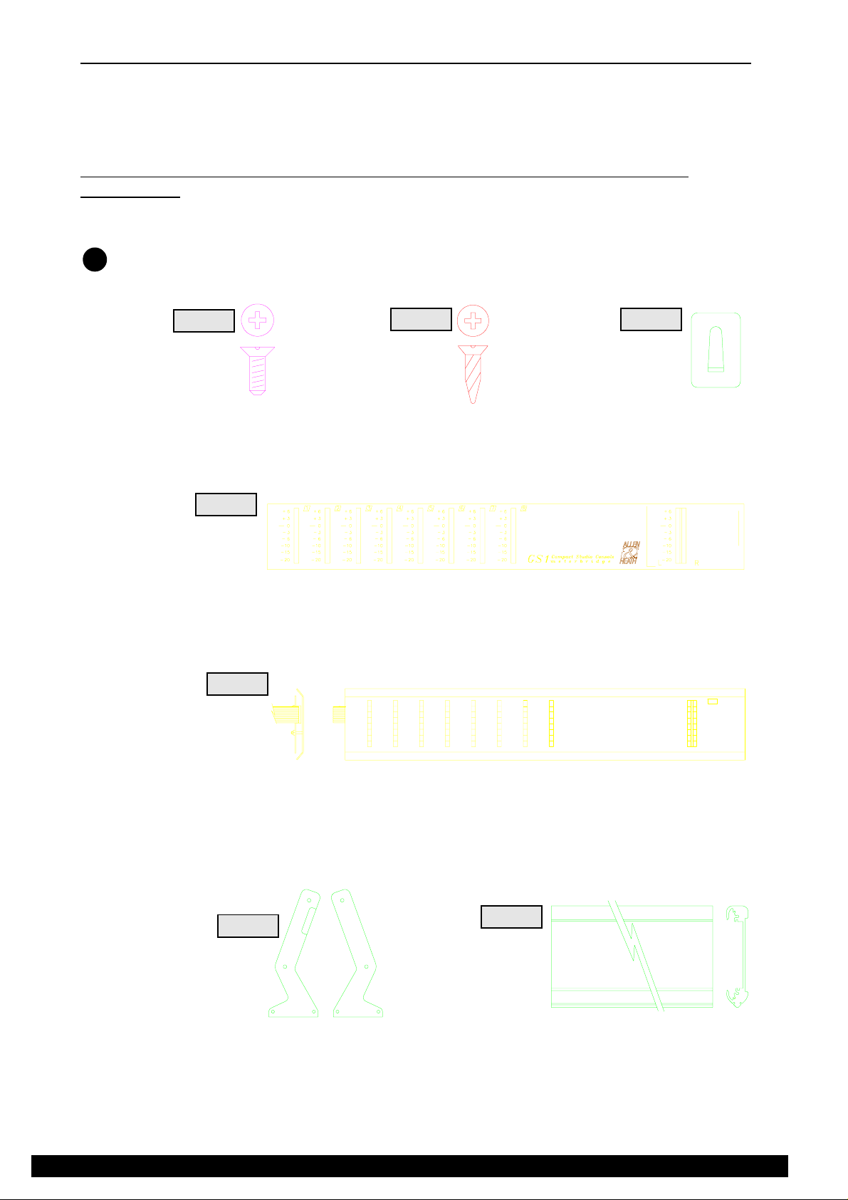
METERBRIDGE OPTION FITTING INSTRUCTIONS
The GS1 Meterbridge option provides the user with full Group and Left/Right metering. The Meterbridge has been
designed to fit either at the rear of the console on the supports provided or at the front as a replacement for the existing
armrest.
Please read the following instructions carefully before attempting to fit the Meterbridge.
Remove the console Power Supply lead and audio cables before fitting the
meterbridge
1
PART NO. AB0074
QUANTITY 4
SCREW 3MM X 8 CSK
PART NO. AA2178
QUANTITY 1
FACIA (SELF ADHESIVE)
Check contents of pack to ensure all parts have been supplied
ITEM 1
ITEM 4
ITEM 2
PART NO. AB0195
QUANTITY 4
SCREW SELF TAP
ITEM 3
PART NO. AB2294
QUANTITY 1
CABLE CLIP IDC
ITEM 5
PART NO.s 002-052,AA2177
QUANTITY 1
FRONT PANEL ASSY
ITEM 6
PART NO.s AA2256,AA2257
QUANTITY 1
SIDE TRIMS L/H R/H
ITEM 7
PART NO. AA2166
QUANTITY 1
EXTRUSION
(SUPPLIED FITTED TO ITEM 5)
ALLEN & HEATH
12 S1SM1
Page 13

ASSEMBLY (REAR POSITION)
As supplied the front panel and PCB are assembled in the extrusion the correct way round for mounting at the rear of
the console.
Attach side trims ITEM 6 to the extrusion ITEM 7 using the self tapping screw supplied ITEM 2 The
2
Left hand side trim has a rebate for the IDC cable. Care should be taken not to trap the cable when attaching
the side trim.
1
Apply self adhesive facia ITEM 4 to the front panel ITEM 5 ensuring correct alignment with the meter
3
slots.
Remove screws from left hand extrusion and plastic end cap and slide out extrusion as shown.
4
It may be necessary to loosen screws "A" to enable side extrusion to slide.
Attach Meterbridge to sides of front panel as shown in using M3
5
screws supplied ITEM 1
Connect IDC cable as shown ensuring correct orientation.
13S1SM1
ALLEN & HEATH
Page 14

Apply the self adhesive cable clip ITEM 3 as shown in the diagram.
6
Route cable as shown below. Replace side extrusion and rear end cap.
The installation is now complete. Replug the console and test for correct operation.
ASSEMBLY (ARMREST POSITION)
To assemble the Meterbridge in the armrest position the Front Panel/PCB assembly ITEM 5 must be removed
2
from the extrusion ITEM 7 and replaced the opposite way round.
1
When replaced the self adhesive Facia ITEM 4 can be applied to the front panel ITEM 5
3
ensuring correct alignment with the meter slots.
ALLEN & HEATH
14 S1SM1
Page 15

Remove screws from left hand extrusion and plastic end cap and slide out extrusion as shown.
4
Remove left hand front end cap held by screws "A" and "B"
Release screws "B" from right hand front end cap and remove existing armrest.
5
Insert Meterbridge into right hand front end cap, replace left hand front end cap ensuring IDC cable exits
through the slot in the end cap.
Route IDC cable under console and connect as detailed previously in step of rear position assembly
instructions
Replace side extrusion and rear end cap.
The IDC cable clip ITEM 3 may be used on base of console to keep IDC cable neat.
5
The installation is now complete. Replug the console and test for correct operation.
15S1SM1
ALLEN & HEATH
Page 16

ORDERING SPARE PARTS
ORDERING A CONSOLE
MODEL DESCRIPTION ORDER CODE
GS1 240V 16 channel GS1 + PSU (240V) GS1/240
GS1 220V 16 channel GS1 + PSU (220V) GS1/220
GS1 120V 16 channel GS1 + PSU (120V) GS1/120
GS1 110V 16 channel GS1 + PSU (110V) GS1/110
GS1 100V 16 channel GS1 + PSU (100V) GS1/100
ORDERING AN OPTION
MODEL DESCRIPTION ORDER CODE
GS1 EXPANDER 8 channel Expander GS1-EX
GS1 METERBRIDGE Group & L/R meterbridge GS1-MP
ORDERING A POWER SUPPLY
MODEL DESCRIPTION ORDER CODE
240V 240V Power Supply unit AM2211
220V 220V Power Supply unit AM2212
115V 120V and 110V Power Supply Unit AM2213
100V 100V Power Supply Unit AM2214
MANUALS AND SUPPORT DOCUMENTATION
DESCRIPTION ORDER CODE
GS1 User Guide AP2061
GS1 Service Manual AP2064
GS1 Expander Fitting Instructions AP2313
GS1 Meterbridge Fitting Instructions AP2300
SERVICE TOOLS
DESCRIPTION ORDER CODE
1-point Crosshead screwdriver (M3, 4AB) AT0004
SOFTWARE UPGRADE:
The GS1 software is stored in a Microcontroller which is socketed. To replace the Microcontroller the console will have
to be disassembled as detailed in Stage 1 of the CONSOLE DISASSEMBLY section of this manual.
To order a replacement, please contact ALLEN & HEATH and notify us of your console serial number, its present
Microcontroller version and code number, and reason for replacement.
ALLEN & HEATH
16 S1SM1
Page 17

ORDERING A SPARES KIT
It is recommended that the spares kit order code 002-014 is held and maintained by the service agent to enable in-field
service repairs to the GS1 independent of the ALLEN & HEATH factory. Commonly available items such as resistors,
capacitors, tools and soldering equipment are not included. The contents of the kit is listed here. Individual spare parts
may be ordered. Please quote the description and order code for the part required.
DESCRIPTION ORDER CODE QTY
Fixings:
Screw 4AB x 5/16" Pan Pozi Black AB0057 10
Screw 6AB x 3/8" Pan Pozi Black AB0062 5
Screw M3 x 8mm Pan Pozi Black AB0073 10
Screw 6B x 1/4" Pan Pozi Black AB2224 5
Nylock nut M3 AB0102 5
Washer M3 shakeproof AB0244 5
Pillar Support 6.4mm AB2171 5
Pillar snap-in 6.4mm AB2233 5
Spacer M3 x 6.4mm AB2218 5
Knobs and caps
Fader knob white+black line AJ2163 10
Fader knob red+white line AJ2164 5
Rotary knob grey+red top AJ2188 10
Rotary knob grey+blue top AJ2194 10
Rotary knob grey+green top AJ2195 5
Rotary knob grey+dark grey top AJ2196 10
Rotary knob grey+yellow top AJ2197 10
Rotary knob grey+brown top AJ2198 10
Switch Button AJ8071 10
Potentiometers, switches and connectors
Fader 10kA 100mm ALPS - MONO AI8055 5
Fader 10kAx2 100mm ALPS - STEREO & LR AI8056 5
Rotary 200kC stereo - MID SWEEP AI2042 3
Rotary 5kRD - MIC GAIN AI8059 5
Rotary 20kB centre click - HF,MF,LF AI8060 10
Rotary 20kK - AUX 2/4, 3/5, TAPE RTN LEV, AUX MASTERS AI8061 10
Rotary 5kB centre click - PAN AI8062 5
Rotary 20kK stereo - AUX 1, STEREO RTN LEV & MONITOR LEV AI8063 10
Rotary 20kBx2 - STEREO HF & LF AI8064 5
Switch 2PCO latching AL8057 5
Switch 2PCO momentary AL8058 5
Jack socket - LINE, INSERT, STR RETURN AL8072 5
Jack socket - AUX OUTS, HPHONES AL8073 5
XLR 3 Pin Female - MIC AL8074 5
Dual Phono socket - TAPE IN/OUT, LR OUT AL0577 3
DIN 5 Pin 180º - MIDI AL0095 1
DIN 5 Pin 240º - CONSOLE POWER AL2113 -
LEDs and Semiconductors
LED 3mm T1 Green AE0085 5
LED 3mm T1 Red AE0086 3
LED Bar 4x Green AE0303 2
LED Bar 1x Green + 3x Red AE0347 1
Transistor BC214C PNP AE0031 5
Transistor BC546C NPN AE2253 5
Transistor 2SB737 PNP AE8069 5
Transistor J111 FET AE0083 5
IC NE5532N Dual Op Amp AE0221 5
17S1SM1
ALLEN & HEATH
Page 18

DESCRIPTION ORDER CODE QTY
IC TLO72 Dual Op Amp (SIL Package) AE8070 5
IC LM339 Quad Comparator AE0071 2
IC CMOS 4053B AE0117 1
IC CMOS 4051B AE0118 1
IC CMOS 4099B AE0238 1
IC 6N136 Opto isolator AE0222 1
IC Regulator 7815 (+15V DC) AE0047 1
IC Regulator 7915 (-15V DC) AE0048 1
IC Regulator 783 (+48V DC) AE0214 1
IC CMOS 74HC4051SMD (Expander only) AE2161 IC CMOS 74HCF4099 SMD (Expander only) AE2162 IC TL072 Dual Op Amp (DIL Package) (Expander only) AE0046 -
MISCELLANEOUS
Insulating Kit (voltage regulators) AA0693 2
Plastic End Cap set - front & rear, L&R AA2168 Packaging (box, lid & fittings) AN2072 Expander Harness 16way IDC AL2119 Expander Harness 26way IDC AL2154 Meterbridge Harness 16way IDC AL2155 -
ALLEN & HEATH
18 S1SM1
Page 19

TECHNICAL DIAGRAMS
This section includes the circuit diagrams and
illustrations plus any technical bulletins
Page 20

GS1 CONSOLE CIRCUIT DIAGRAM PCB KEY & LINK OPTION POSITIONS
The areas outlined on the PCB correspond to the sheet number on the circuit diagram C2018. For a detailed PCB component
ident refer to PCB fig I and fig II on the following pages.
7
3+4
8
PCB fig. II
3+4 3+4
7
PCB fig. I
3
1Sheet no: 2 1+4 2+4 1+4 2+4 1+4 2+4 5+6
Phantom Power
link options
5
(PP or +48V)
( 8 off)
5
Aux 1 link options:
Tape Return or
Channel pre-fade
( 8 pairs)
CH 1 CH 2 CH 3 CH 4 CH 5 CH 6 CH 7 CH 8 CH 9/10 CH 11/12 CH 13/14 L-RCH 15/16 F KEYS
7
Page 21

Page 22

PCB COMPONENT LAYOUT FOR CHANNELS 1 TO 8
PCB fig.I
Page 23

PCB COMPONENT LAYOUT FOR CHANNELS 9 TO 16 & MASTER L-R
PCB fig.II
Page 24

Page 25

Page 26

Page 27

Page 28

Page 29

Page 30

Page 31

Page 32

GS1 EXPANDER CIRCUIT DIAGRAM PCB KEY & LINK OPTION POSITIONS
The areas outlined on the PCB correspond to the sheet number on the circuit diagram C2054. For a detailed PCB component
ident refer to the Expander PCB component layout on the following page
Phantom Power link options
(PP or +48V)
( 8 off)
1 2 1+3 2+3 1+3 2+3 1+3 2+3
Sheet no:
3
*
3
3
Aux 1 link options:
*
Tape Return or Channel pre-fade
( 8 pairs)
EX 8EX 7EX 1 EX 2 EX 3 EX 4 EX 5 EX 6
3
Page 33

Page 34

Page 35

Page 36

Page 37

Page 38

 Loading...