

ALLEN & HEATH GR2 User Manual

ALLEN&HEATH
Safety Instructions ............... 3
Introduction ......................... 4
Welcome to the GR2 ........... 5
Features............................... 6
Audio Signal Paths .............. 8
System Function.................. 9
Connecting Power............... 9
Front Panel ..........................10
Rear Panel ...........................11
Configuration Settings......... 12
Zone Remote Wired ............ 14
PL-12 Wall Plate................... 15
Utility Remote ...................... 16
Installation............................ 17
Applications ......................... 18
Specification ........................ 20
Configuration Sheets........... 22
GR2
Audio Zone Mixer
S
S
S
o
o
o
u
u
u
n
n
n
d
d
d
C
C
C
o
o
o
n
n
n
t
t
t
r
r
r
a
a
a
c
c
c
t
t
t
o
o
o
r
r
r
A
A
A
p
p
p
p
p
p
l
l
l
i
i
i
c
c
c
a
a
a
t
t
t
i
i
i
o
o
o
n
n
n
s
s
s
6
6
6
M
M
M
i
i
i
c
c
c
r
r
r
o
o
o
p
p
p
h
h
h
o
o
o
n
n
n
e
e
e
I
I
I
n
n
n
p
p
p
u
u
u
t
t
t
s
s
s
3
3
3
S
S
S
t
t
t
e
e
e
r
r
r
e
e
e
o
o
o
L
L
L
i
i
i
n
n
n
e
e
e
I
I
I
n
n
n
p
p
p
u
u
u
t
t
t
s
s
s
1
1
1
S
S
S
t
t
t
e
e
e
r
r
r
e
e
e
o
o
o
,
,
,
1
1
1
M
M
M
o
o
o
n
n
n
o
o
o
Z
Z
Z
o
o
o
n
n
n
e
e
e
A
A
A
s
s
s
s
s
s
i
i
i
g
g
g
n
n
n
a
a
a
b
b
b
l
l
l
e
e
e
A
A
A
u
u
u
x
x
x
O
O
O
u
u
u
t
t
t
p
p
p
u
u
u
t
t
t
R
R
R
e
e
e
m
m
m
o
o
o
t
t
t
e
e
e
C
C
C
o
o
o
n
n
n
t
t
t
r
r
r
o
o
o
l
l
l
I
I
I
n
n
n
s
s
s
t
t
t
a
a
a
l
l
l
l
l
l
e
e
e
r
r
r
C
C
C
o
o
o
n
n
n
f
f
f
i
i
i
g
g
g
u
u
u
r
r
r
a
a
a
b
b
b
l
l
l
e
e
e
USER GUIDE
INSTALLATION
Publication AP6320
2 GR2 User Guide
This product complies with the European Electromagnetic Compatibility
directives 89/336/EEC & 92/31/EEC and the European Low Voltage
Directives 73/23/EEC & 93/68/EEC.
NOTE: Any changes or modifications to the unit not approved by Allen & Heath could void the
compliance of the unit and therefore the user’s authority to operate it.
GR2 User Guide AP6320 Issue 1
Copyright © 2005 Allen & Heath Limited. All rights reserved
Whilst we believe the information in this guide to be reliable we do not assume responsibility for
inaccuracies. We also reserve the right to make changes in the interest of further product
development.
Allen & Heath Limited
Kernick Industrial Estate,
Penryn, Cornwall, TR10 9LU, UK
http://www.allen-heath.com
Limited One Year Warranty
This product has been manufactured in the UK by Allen & Heath Limited and is
warranted to be free from defects in materials or workmanship for a period of one
year from the date of purchase by the original owner.
To ensure a high level of performance and reliability for which this equipment has
been designed and manufactured, read this user guide before operating. In the
event of a failure, notify and return the defective unit to Allen & Heath Limited or
its authorised agent as soon as possible for repair under warranty subject to the
following conditions
Conditions Of Warranty
1. The equipment has been installed and operated in accordance with the
instructions in this user guide
2. The equipment has not been subject to misuse either intended or accidental,
neglect, or alteration other than as described in the user guide or service
manual, or approved by Allen & Heath.
3. Any necessary adjustment, alteration or repair has been carried out by Allen
& Heath or its authorised agent.
4. The defective unit is to be returned carriage prepaid to Allen & Heath or its
authorised agent with proof of purchase.
5. Units returned should be packed to avoid transit damage.
In certain territories the terms may vary. Check with your Allen & Heath agent for
any additional warranty which may apply.
GR2 User Guide 3
Important Safety Instructions
READ THESE INSTRUCTIONS BEFORE PROCEEDING
This symbol, wherever it appears, alerts you to the presence of uninsulated
dangerous voltage inside the enclosure that may be sufficient to constitute a
risk of electric shock.
This symbol, wherever it appears, alerts you to important operating and
maintenance instructions in the accompanying literature.
ATTENTION: RISQUE DE CHOC ELECTRIQUE – NE PAS OUVRIR
Read instructions: Read and retain these safety and operating instructions for future reference.
Heed all warnings printed here and on the appliance. Follow the operating and user instructions
printed in this user guide.
Do not remove cover: This appliance contains no user serviceable parts inside. Operate the
appliance with its cover correctly fitted.
Power sources: Connect the appliance to a mains power outlet only of the type described in
this user guide and marked on the rear panel. Use the power cord with sealed mains plug
appropriate for your local mains supply as provided with the console. If the provided plug does not fit
into your outlet consult your service agent for assistance.
Power cord routing: Route the power cord so that it is not likely to be walked on, stretched
or pinched by items placed upon or against it.
Grounding: Do not remove or tamper with the ground connection in the power cord. Do not
defeat the grounding and polarisation means of the power cord plug. A polarised plug has two
blades with one wider than the other. A grounding type plug has two blades and a third grounding
prong. The wide blade or the third prong are provided for your safety. When the provided plug does
not fit your outlet, consult an electrician for replacement of the obsolete outlet.
Water and moisture: To reduce the risk of fire or electric shock do not expose this appliance
to rain or moisture. Do not place containers of liquids on surfaces where liquid may spill into any
openings. Do not expose the appliance to dripping or splashing.
Ventilation: The appliance should be situated so that its location or position does not interfere
with its proper ventilation. Do not obstruct its ventilation openings. If the appliance is to be operated
in a rack or other furniture ensure that it is constructed to allow adequate ventilation.
Heat: Do not locate the appliance in a place subject to excessive heat or direct sunlight as this
could be a fire hazard. No naked flame sources such as lighted candles should be placed on or near
the appliance.
Servicing: Switch off the equipment and unplug the power cord immediately if it is exposed to
moisture or spilled liquid, if objects have fallen into the openings, if the power cord or plug have
become damaged, if the appliance has been dropped, during lightning storms, or if smoke, odour or
noise is noticed. Refer servicing to qualified technical personnel only.
Installation: Install and use the appliance in accordance with the instructions printed in this user
guide. Do not connect the output of power amplifiers directly to this appliance. Use audio
connectors and plugs only for their intended purpose.
Operating environment Protect the appliance from excessive dirt, dust, smoke, ash, heat and
vibration when operating and storing.
Cleaning Clean the appliance only with a dry, soft cloth.
CAUTION
WARNING: This apparatus must be earthed.
4 GR2 User Guide
Introduction
This User Guide provides a quick reference to the installation and operation of the GR2 audio
zone mixer. We refer to two types of user in this guide: The Installer configures the unit for the
application and is assumed to have technical knowledge in audio system interconnection and
setup. The Operator is the day to day user of the unit and does not require technical knowledge.
This guide provides technical information for the installer. A Configuration Sheet is included at the
rear of this guide so that the installation settings and instructions for the operator may be logged.
The GR2 offers many configuration possibilities to satisfy the custom requirements of a multitude
of architectural and utility sound applications. To take advantage of this capability, we
recommend that the installer studies the system block diagram to fully understand its signal flow
and control possibilities.
Important Mains plug wiring instructions.
The console is supplied with a moulded mains plug fitted to the AC mains power lead. Follow the
instructions below if the mains plug has to be replaced. The wires in the mains lead are coloured
in accordance with the following code:
The wire which is coloured Green and Yellow must be connected to the terminal in the plug which
is marked with the letter E or with the Earth symbol. This appliance must be earthed.
The wire which is coloured Blue must be connected to the terminal in the plug which is marked
with the letter N.
The wire which is coloured Brown must be connected to the terminal in the plug which is marked
with the letter L.
WIRE COLOUR
TERMINAL
European USA/Canada
L LIVE BROWN BLACK
N NEUTRAL BLUE WHITE
E EARTH GND GREEN & YELLOW GREEN
GR2 User Guide 5
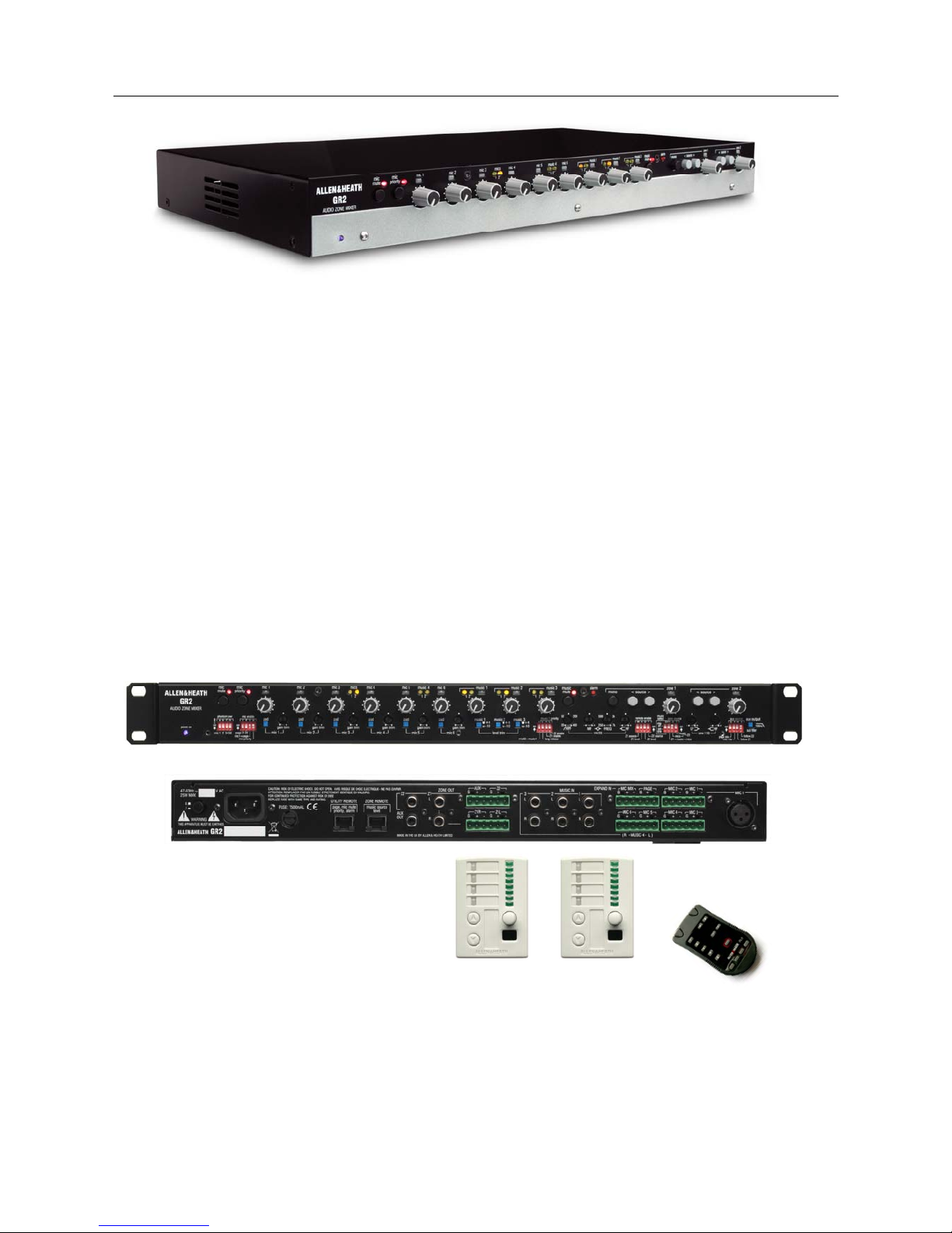
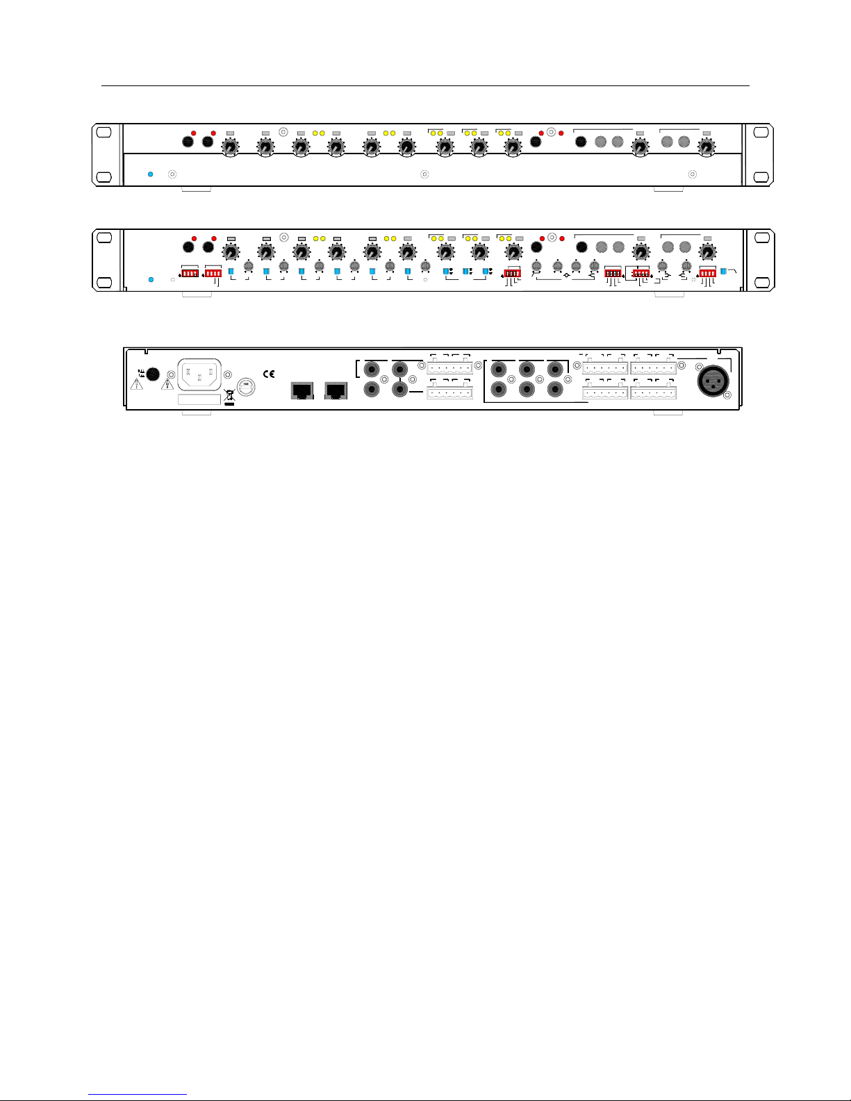
Welcome to the GR2
The GR2 is a compact 9 in 4 out 1U rack mount analogue zone mixer with 6 mic
and 3 stereo line inputs, two zone outputs (1 stereo, 1 mono), and an assignable
mono aux output.
It is configured by the installer for a variety of applications by setting front panel
DIP switches and presets. These are accessible by removing a cover plate
which protects the settings during day-to-day operation, and can be used to
mount a custom ident label. Simple controls such as mute, source select and
level are available to the operator, or can be plugged to lock their function. A
combination of XLR, phono and Phoenix screw terminal connections is provided
to conveniently suit both the freestanding and installed applications. Additional
connections are provided to input external paging and alarm audio signals, and
to expand the number of mics beyond 6 by linking GR2 units. Exceptional
capability is provided with functions such as paging, mic priority, music
override, alarm input, and independent mic and zone EQ.
Each input channel and zone output is provided with its own level control and
signal meter. Level and/or source selection for each zone can be configured for
local front panel or remote control using industry standard 10V control. The
installer can make simple potentiometer/rotary switch wall plates, interface with
third party systems such as AMX, or use the Allen & Heath PL12 wall plates with
or without the optional PL-5 infra-red controller. A utility socket allows remote
control of page selection, mic muting and priority, and alarm trigger.
Stereo and mono zones each with local or remote source selection and level…
Aux output for additional zone, recording, sub bass feed, mic expander…
Configure as 6 mic / 3 stereo line, or 4 mic / 4 stereo line, mic expander…
Source select or mix all operating modes…
Page ducking, music override, mic priority, alarm override…
Remote control…
6 GR2 User Guide
Features
6 (4) mic / line inputs
Mic 1 balanced Phoenix terminal plug and XLR, 2-6 Phoenix
Selectable +15V phantom power (mic 1,2,34,56)
Gain trims and pad switches protected behind front cover plate
Mic or line level capability (-60dBu to +20dBu signal sensitivity)
Mic priority for chairman override with panel and remote control
Mic priority on mic 1 (or 2 if a paging mic is configured on mic 1)
Configurable as 6 mic + 3 stereo or 4 mic + 4 stereo inputs
Mic / line inputs 5/6 can be configured as stereo music input 4
Music 4 input balanced on Phoenix plug for long cables runs
3 band mic EQ with swept HPF, swept MF and shelf HF
Mic expander input
0dBu line level balanced on Phoenix plug
Aux output can be configured as a 0dBu mic expander send
Dedicated paging channel with 2 sources
Configurable from Mic / line 1 input, and/or
Balanced page input on Phoenix plug (ext paging or alarm)
Preset page channel EQ for speech intelligibility
Ducking of zone program on presence of page mic signal
External switching to enable paging to zone 1 and/or zone 2
Aux output can be configured as a page feed to other units
3 (4) stereo line music inputs
+4/-10 level setting protected behind front cover plate
One-at-a-time or mix all source selection
Independent source selection for each zone
Panel or remote level and/or source selection
Music source mute switch
Stereo input 1 configurable as priority input (jukebox, adverts)
Overrides other selections on presence of audio signal
Short or long priority release time
WARNING
THIS APPARATUS MU ST BE EARTHED.
GR2
ZONE OUT
AUX
Z1
Z2
OUT
L
R
MUSIC IN
1
2
3
L
RLRLR
-G+
Z1L
MIC 1
G-+
Z1R
-G+
Z2
G-+
AUX
-G+
MIC 3
G-+
MIC 4
-G+
MIC 1
G-+
MIC 2
-G+
MIC 5
G-+
MIC 6
-G+
PAGE
G-+
MIC MIX
ZONE REMOTEUTILITY REMOTE
EXPAND IN
( R - MUSIC 4 - L )
MADE IN THE UK BY ALLEN & HEATH LIMITED
ATTENTION: REMPLACER PAR UN FUSIBLE STRICTEMENT IDENTIQUE EN VALEURS.
FOR CONTINUED PROTE CTION AGAINST RISK OF FIRE
CAUTION: RISK OF ELECTRIC SHOCK. DO NOT OPEN. AVIS : RISQUE DE CHOC ELECTRIQUE - NE PAS OUVRIR.
REPLACE FUSE WITH S AME TYPE AND RATING.
ALLEN&HEATH
WARNING
THIS APPARATUS MU ST BE EARTHED.
GR2
ZONE OUT
AUX
Z1
Z2
OUT
L
R
MUSIC IN
1
2
3
L
RLRLR
-G+
Z1L
MIC 1
G-+
Z1R
-G+
Z2
G-+
AUX
-G+
MIC 3
G-+
MIC 4
-G+
MIC 1
G-+
MIC 2
-G+
MIC 5
G-+
MIC 6
-G+
PAGE
G-+
MIC MIXEXPAND IN
( R - MUSIC 4 - L )
MADE IN THE UK BY ALLEN & HEATH LIMITED
ATTENTION: REMPLACER PAR UN FUSIBLE STRICTEMENT IDENTIQUE EN VALEURS.
FOR CONTINUED PROTE CTION AGAINST RISK OF FIRE
CAUTION: RISK OF ELECTRIC SHOCK. DO NOT OPEN. AVIS : RISQUE DE CHOC ELECTRIQUE - NE PAS OUVRIR.
REPLACE FUSE WITH S AME TYPE AND RATING.
ALLEN&HEATH
100 - 240V~
47-63Hz ~ 25W MAX
FUSE: T1AL
AUDIO ZONE MIXER
GR2
ALLEN&HEATH
prioritymute
mic 3mic 2mic 1
mic 6mic 5mic 4 music 4mics zone 1 zone 2alarmmusic 3music 2music 1
mute >mono < source ><source
page Z2
56342
Z1
mic1=page
1
mic priority
mic enable
phantom pwr
!
ABCD
+4
pad pad
-10
+4
-10+4-10
padpadpad
gain trim
mic 1
level trim
music 1music 2music 3
mic 2 mic 3 mic 4 mic 5
long release
mic56=music4
Z1 enable
Z2 enable
Z1 source
Z2 level
Z2 source
Z1 level
music
LF
follow Z1
follow Z2
mic mix
page mix
mics
zone 1 EQ
sel
one
remote enable
zone source
music
select
EFGH
IJKL
music 1 priority
MNOP
QRST
21
21
power on
on
mic
on
gain trim gain trim gain trim gain trim gain trim
on on
mix
all
Z1=music+mics
Z2
on
HPF HF
mic EQ
MF FREQ
20 400 - +
on
+-+-+-
HF
UVWX
aux source
100Hz
aux output
sub filter
mic mic music
pad
mic 6
212121
50
200
180 5k
300
2k
AUDIO ZONE MIXER
GR2
ALLEN&HEATH
prioritymute
mic 3mic 2mic 1 mic 6mic 5mic 4 music 4mics zone 1 zone 2
alarm
music 3music 2music 1
mute >mono <source ><source
21
21
mic mic music
212121

GR2 User Guide 7
2 zone outputs, one stereo one mono
0dBu, duplicated on RCA phono and balanced Phoenix
Zone 1 configurable as music only or music+mics mix
Zone 2 configurable as mics, music or music+mics mix
VCAs for page ducking, alarm override and remote level control
2 band zone 1 music EQ with shelving LF and HF
Zone 1 stereo/mono switch
Mono Aux output
0dBu, duplicated on RCA phono and balanced Phoenix
Configurable as page out, mic mix, zone 1 (mono) or zone 2
Switchable low pass filter for sub bass application
Front panel controls
9 input channels with level and signal/peak meters
Input level control provides +6dB boost
2 zones with level, source <> select and signal/peak meters
Source active indicators for each zone
Mic priority, mic mute, music mute and alarm active indicators
Zone Remote RJ45
CAT5 cable to connect zone 1 and/or zone 2 remote
Standard 0-10V DC level control, 0V=off, +10V=on
0-10V stepped for remote selection of up to 4 sources plus off
Provides +10V for reference and for remote circuit power
Many remote control possibilities including:
Level control using hard wired potentiometer
Resistive ladder source select using hard wired rotary switch
Resistive ladder source select using 2-pole switches with LEDs
Third party control (AMX/Crestron) using 10V interface
Optional PL-12 wall plate with IR and extended functions
PL-5 hand held IR remote works with PL-12
Utility Remote RJ45
Logic control – switch to ground = active
Provides +10V for remote circuit power
Interfaces with third party and custom systems
Mute control for mic mix
Priority mic override switching
Alarm switch mutes all except page channel
External page to zone 1, 2 enable
Connections
Phoenix screw terminal plugs for pre-wired installation
Standard XLR and RCA phono connectors for plug-and-play
RJ45 for CAT5 cable connection to remotes
Universal 100-240V.AC IEC mains input
Mechanics
Compact 1U rack or desk mount
Removable front plate to access installer configuration settings
Dip switches letter coded for installer convenience
Level controls can be removed and plugged for protection
Bolt-on rack ears provided for 19” rack mounting
Plastic feet fitted for desk mounting
No need to remove the cover, all settings accessible on front
8 GR2 User Guide
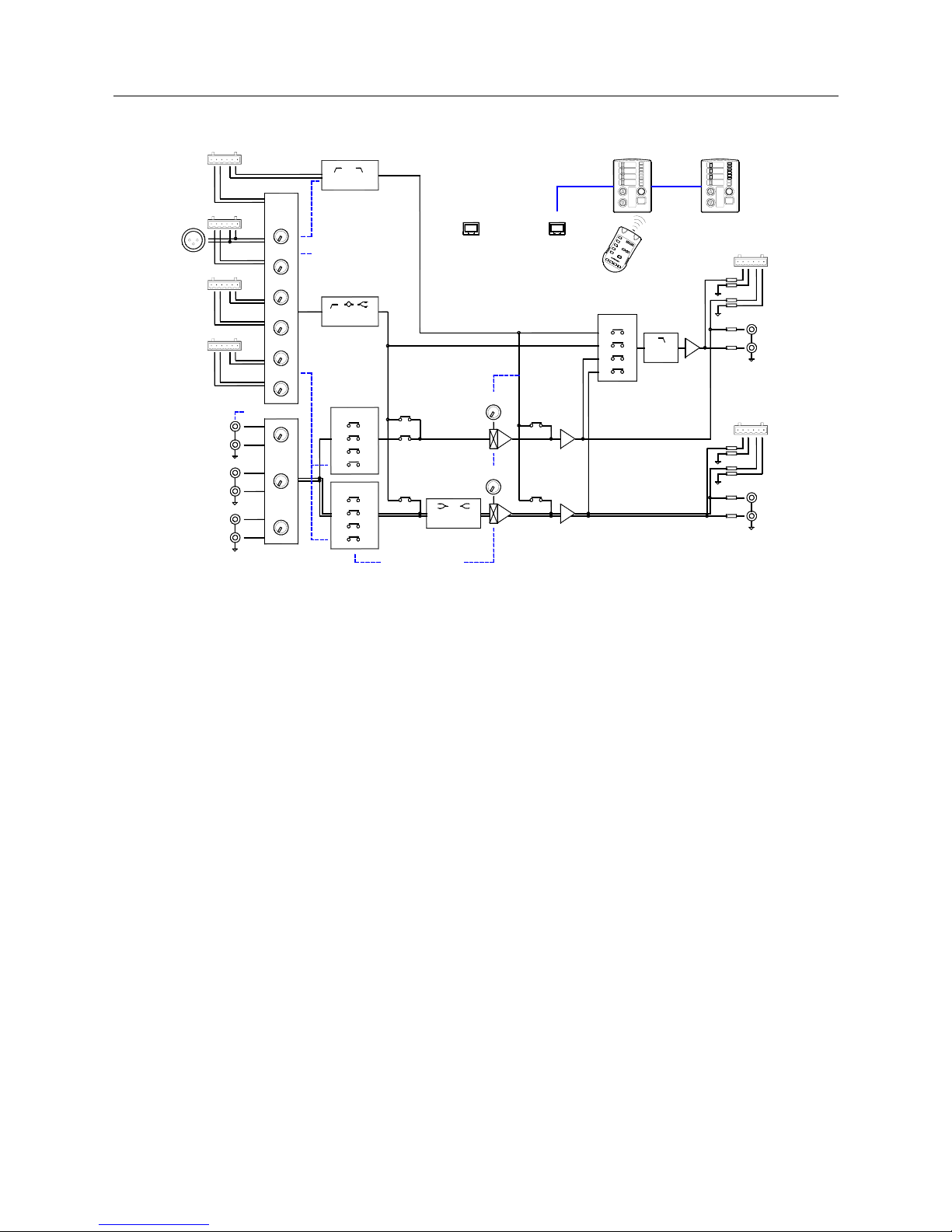
Audio Signal Paths Simplified block diagram
Page mix - Overrides the music/mic selection. The input is from the external
page input and/or from mic 1 if it is configured as a paging mic. The page mix
EQ provides high pass and low pass filters tuned for paging speech. The mix
routes directly to the zone outputs and is not affected by the output level front
panel or remote controls. Signal detected on the page mix causes ducking of
any page enabled zone.
Mic mix - The performance or conference mic mix. Depending on the
configuration, the mic mix may comprise 3, 4, 5 or 6 mic inputs being sourced
from mics 1-6, 2-6, 1-4 or 2-4. The mix of mic inputs can be routed to the zones
via the VCAs, or direct to the aux output. A dedicated mic EQ provides a swept
frequency high pass filter, swept frequency peak/dip mid, and shelving high
frequency cut/boost tuned to deal with typical live performance or conference
microphone mixing.
Music mix - An independent mix of the music sources for each zone. Each
has operator controllable music source selection. The number of sources that
can be selected by the operator depends on the configuration, either 2, 3 or 4.
Alternatively, all sources can be permanently mixed together. Music 1 input can
have priority over the other sources for applications such as jukebox or live /
pre-recorded retail announcements. Mics 5/6 can be configured as an
additional ‘music 4’ balanced stereo source. This allows either 6 mic / 3 stereo
music or 4 mic / 4 stereo music capability.
Zone 1 and 2 VCA mixes - The music plus mic mix for each zone. Zone 1
is stereo, zone 2 is mono. Routed through a VCA, the mix is overridden during
paging or when the alarm input is triggered. The mic mix can be added to the
pre-VCA music mix. Zone 1 has a 2-band EQ and mono switching.
Aux mix - An independent mono output which can be sourced from any
combination of the page mix, mic mix, post-level zone 1 or zone 2 mix.
Applications include routing the page mix only to create a single paging source
to daisy chain through other GR2 units, routing mic mix only to expand the
number of mics to a second GR2, feeding a conference recorder, or creating a
mono sum and filtered sub bass mix to compliment the zone 1 stereo output.
MIC1
EXPAND
PAGE EQ
PAGE MIX
EXT PAGE IN
MIC MIX
MIC EQ
MUSIC1
MUSIC2
MUSIC3
< SELECT >
1
2
3
4
1
2
3
4
LEVEL
MICS
MICS
ZONE1 EQ
SOURCE
PAGE MIX
MIC MIX
ZONE1
ZONE2
LEVEL
PAGE
PAGE
SUB EQ
AUX
ZONE2
AUX
MIC2
MIC3MIC4
MIC5MIC6
MIC MIX
ZONE1 MIX
ZONE2 MIX
SOURCE
ZONE2AUX
ZONE1
ZONE1
STEREO
MONO
MIC5/6, MUSIC4
PAGE MIC
MUSIC PRIORITY
MIC PRIORITY
DUCKING
UTILITY REMOTE
Z1 PAGE ENABLE
ZONE REMOTE
MIC MUTE
MIC PRIORITY
ALARM OVERRIDE
Z1 SOURCE SELECT
Z1 LEVEL
Z2 SOURCE SELECT
Z2 LEVEL
Z2 PAGE ENABLE
PHANTOM POWER
MUSIC MUTE
MIC MUTE
MONO / STEREO
GR2 AUDIO ZONE MIXER
MUSIC
10V LOGIC
< SELECT >
GAIN / PAD
LINE +4/-10
L
R
L
R
L
R
L
R
PL-12 WALL PLATE
5
4
3
2
1
P
L
5
5
4
3
2
1
6
7
8
9
1
2
1
3
1
0
1
1
1
4
PL-5 IR CONTROLLER
REMOTE CONTROL
 Loading...