

Page 1

ALLEN&HEATH
WARNING – HIGH VOLTAGES
Power Supply Unit (PSU) work should only
be carried out by qualified personnel.
We recommend that you use an approved Allen & Heath
service centre for all power supply work.
Please contact your local Allen & Heath distributor for more details.
http://www.allen-heath.com/
Page 2

GR1
ZONE MIXER
SERVICE
MANUAL
PUBLICATION AP2059
Page 3

INTRODUCTION
The information presented in this manual is intended for competent technical personnel to carry out service and product
support for the GR1. We assume that the reader is familiar with the related electronic theory and audio terminology,
and is able to carry out basic servicing, fault-finding and repair of audio equipment of this type. Service personnel should
also be familiar with audio systems, mains earthing and power requirements, as well as handling precautions.
For further information on the operation and application of the GR1 please refer to the USER GUIDE publication
AP2057 supplied with each unit.
Whilst we believe the information in this manual to be reliable we do not assume responsibility for inaccuracies. We
also reserve the right to make changes in the interest of further product development.
SERVICE AND TECHNICAL SUPPORT
Under normal conditions the GR1 does not require user maintenance or internal calibration. Any service work required
should be carried out by qualified technical personnel only.
We are able to offer further product support through our worldwide distribution network. To help us provide the most
efficient service please would you quote the console serial number in any communication regarding this product.
SAFETY WARNING !
Mains electricity is dangerous and can kill. Mains voltage is present within the GR1. Do not
remove the top cover with mains connected. Do not carry out any work within the unit while
it is powered except for installation calibration. High voltage components are insulated for
safety but should not be touched with power applied. The mains voltage setting is factory
wired and marked on the rear panel. Check that this matches your local mains supply. Check
your mains wiring and earthing before switching on.
DO NOT REMOVE THE MAINS EARTH CONNECTION!
The chassis is always connected to mains earth regardless of any settings of the Ground
(earth) Lift option links.
This manual is printed in three sections:
SECTION A
is a reprint of the USER GUIDE for quick reference.This may also assist the service agent in dealing with
user related problems. From our experiences with customer problems, most are due to incorrect use or
installation of the console and/or connected equipment. This is often due to the customer not reading or
misinterpreting the instructions in the user guide.
SECTION B
provides technical descriptions, service procedures, and how to order spare parts. The contents of the
standard service agent spares kits are also listed.
SECTION C
provides a complete set of circuit diagrams, printed circuit and assembly drawings.
copyright © 2002 ALLEN & HEATH Ltd. All rights reserved
ALLEN & HEATH
Publication ...................... AP2059 Issue 2
2 R1SM1
Page 4

CONTENTS
SECTION A
INTRODUCTION ................................................................................................................ 1
SERVICE & TECHNICAL SUPPORT ................................................................................. 1
PRECAUTIONS .................................................................................................................. 1
INTERCONNECTIONS ....................................................................................................... 2
ADJUSTING THE LEVELS ................................................................................................. 2
SPECIFICATION ................................................................................................................ 3
CONNECTIONS ................................................................................................................. 3
INSTALLATION .................................................................................................................. 4
CONNECTING POWER ..................................................................................................... 4
FRONT PANEL CONTROLS .............................................................................................. 5
CONFIGURATION .............................................................................................................. 6
EARTHING THE AUDIO SYSTEM ..................................................................................... 7
MIC INPUTS ....................................................................................................................... 7
LINE INPUTS ...................................................................................................................... 8
CHANNEL DIRECT OUTPUTS .......................................................................................... 8
ROUTING THE CHANNELS ............................................................................................... 9
L,R,M SYS-LINK INPUT/OUTPUT ..................................................................................... 9
MAIN OUTPUTS ................................................................................................................. 9
PRIORITY DUCKING SYSTEM .......................................................................................... 10
COMPRESSOR/LIMITERS ................................................................................................ 10
REMOTE CONTROL .......................................................................................................... 11
ALARM OVERRIDE ............................................................................................................ 12
INPUT EXPANSION WITH SYS-LINK ............................................................................... 13
OUTPUT EXPANSION WITH SYS-LINK ........................................................................... 14
BLOCK DIAGRAM .............................................................................................................. 15
SECTION B
TECHNICAL DESCRIPTION .............................................................................................. 2
WHEN A FAULT IS SUSPECTED ...................................................................................... 3
REMOVING THE PCB ........................................................................................................ 4
VCA CALIBRATION ............................................................................................................ 5
ORDERING SPARE PARTS .............................................................................................. 6-7
SECTION C
TECHNICAL BULLETINS ................................................................................................... 2
FRONT & REAR PANEL LAYOUT ..................................................................................... 3
BLOCK DIAGRAM .............................................................................................................. 4
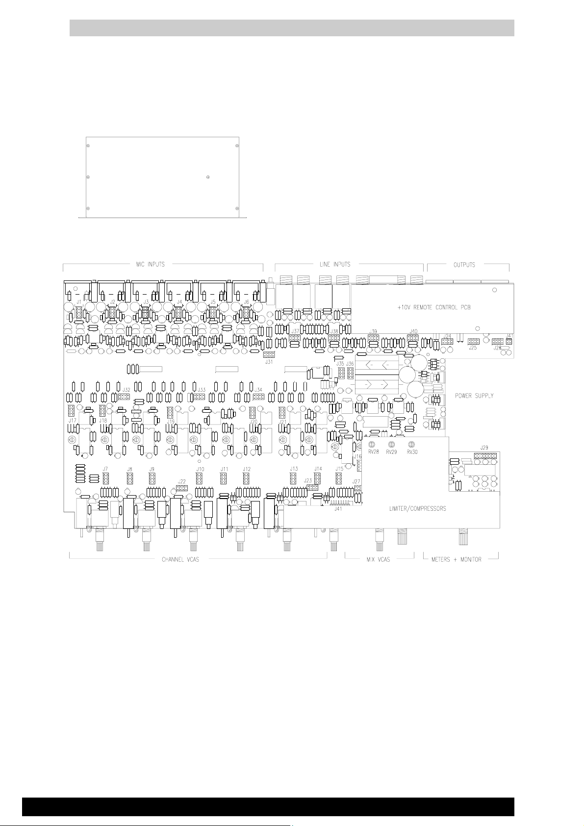
INTERNAL LAYOUT ........................................................................................................... 5
PCB COMPONENT IDENT ................................................................................................ 6
PCB COMPONENT VALUES ............................................................................................. 7
CIRCUIT DIAGRAMS (11 pages) ....................................................................................... 8-18
AC MAINS VOLTAGE ......................................................................................................... 19
3R1SM1
ALLEN & HEATH
Page 5

SECTION A
GR1 USER GUIDE
The user guide is reprinted here for easy
reference during service operations.
A
R1SM1
Section A - 1
ALLEN & HEATH
Page 6

GR1
INTRODUCTION
The GR1 continues ALLEN & HEATH’s commitment to provide high quality audio equipment engineered to meet
the exacting requirements of today’s audio business. It brings you the latest in high performance technology and
offers the reassurance of over two decades of manufacture and customer support.
This user guide presents a quick reference to the function, application and installation of the GR1. For further
information on the basic principles of audio system installation and engineering please refer to one of the specialist
publications available from bookshops and audio equipment dealers.
Whilst we believe the information in this guide to be reliable we do not assume responsibility for inaccuracies. We
also reserve the right to make changes in the interest of further product development.
SERVICE AND TECHNICAL SUPPORT
Under normal conditions the GR1 does not require user maintenance or calibration. Internal links and preset controls
may be set to configure the unit during installation. Any service work required should be carried out by qualified
service personnel only.
We are able to offer further product support through our worldwide network of approved dealers and service agents.
To help us provide the most efficient service please would you keep a record of the unit serial number, and date and
place of purchase to be quoted in any communication regarding this product.
SAFETY WARNING !
Mains electricity is dangerous and can kill. Mains voltage is present within the GR1. Do not
remove the top cover with mains connected. Do not carry out any work within the unit while
it is powered except for installation calibration. High voltage components are insulated for
safety but should not be touched with power applied. The mains voltage setting is factory wired
and marked on the rear panel. Check that this matches your local mains supply. Check your
mains wiring and earthing before switching on.
DO NOT REMOVE THE MAINS EARTH CONNECTION!
The chassis is always connected to mains earth to ensure your safety. An internal link may
be set to remove audio 0V from mains earth (ground lifted) to avoid ground loop problems.
PRECAUTIONS.
zz
z AC POWER: Check the rear panel power supply label for the correct AC mains voltage setting.
zz
zz
z CONNECTIONS: Use audio connectors and cables only for their intended purpose. Do not connect any
zz
source of AC or DC power to the console audio inputs and outputs. Do not connect the
output of power amplifiers directly to the console.
zz
z VENTILATION: Do not cover the unit in any way. Position the unit in a well ventilated location in the
zz
rack.
zz
z CLEANING: Avoid the use of chemicals, abrasives and solvents. The control panel is best cleaned
zz
with a soft brush and lint-free cloth.
zz
z LUBRICATION: The switches and potentiometers are lubricated for life. The use of electrical
zz
lubricants on these parts is not recommended.
zz
z DIRT, DUST, SMOKE and MOISTURE: Prevent damage to the moving parts, such as switches and
zz
potentiometers, and cosmetics by avoiding drinks spillage, tobacco ash and smoke, and
exposure to rain and condensation. Protect from excessive dirt, dust, heat and
vibration.
USER GUIDE
3
Page 7
GR1
INTERCONNECTIONS
Where possible use balanced connections for the inputs and outputs to minimise noise pick-up. Avoid running audio
cables near to mains or lighting cables or thyristor dimmer units, power supplies etc. These may cause audible hum
and buzz. The use of low impedance sources significantly reduces interference pick-up. Check the cables for correct
wiring to avoid problems with phase reversal and unreliable connection. The GR1 follows the convention for XLR
pin 2 and jack tip = signal hot (+). Always use balanced cables when connecting to phantom powered microphones.
MAKE SURE THAT +48V IS DISABLED USING THE INTERNAL LINK OPTIONS WHEN THE
CHANNEL INPUT XLRS ARE CONNECTED TO NON-PHANTOM POWERED OR LINE SOURCES.
If ground loops cause problems connect the cable screen at one end only as described below. Balanced outputs may
be connected to unbalanced inputs and vice versa by linking the signal cold (-) to 0V ground as follows:
Balanced output to Balanced input - Connect cable screen at destination only using the output XLR pin 1
ground lift internal option link.
Balanced output to Unbalanced input - Connect screen at source only. Link the -ve output to 0v at the output
connector.
Unbalanced output to Balanced input - Connect cable screen at destination only using the output XLR pin
1 ground lift internal option link. Link the -ve input to 0V at the input connector.
ADJUSTING THE LEVELS
For best performance it is important that the audio signal levels are adjusted for “normal operating level”. If too high
the signal peaks will be clipped resulting in a harsh distorted sound, and if too low the signal-to-noise ratio is reduced
resulting in excessive background hiss.
For best results operate the unit with the output meters averaging ‘0’. This gives a nominal internal operating level
of -2dBu with ample headroom of +23dB to allow for the peaks. The corresponding XLR output level may be set
to one of three standard line levels: -10dBV (300mV low level), 0dBu (0.775V), +4dBu (high level). The 1/4" jack
line inputs may also be set to one of these three levels. The XLR MIC inputs may be set to match the connected source
by adjusting the rear panel gain trimmers. A 20dB attenuator pad may be enabled by setting the internal link options
for high output microphones or line level sources. The GR1 offers comprehensive signal level checking. Each
channel includes a PEAK indicator which shows signal peaks 5dB before clipping. Reduce the gain trim setting or
set the line inputs for a higher operating level if the indicator flashes continually. The signal quality and level of a
single channel may be checked by setting its level control fully on (clockwise) and the other channels off. Adjust
the gain for an average '0' reading on the output meter. If only the output PEAK indicators flash when several channels
feed the mix then reduce the overall channel levels.
4
USER GUIDE
Page 8
GR1
0 dBu = 0.775 Volts RMS
0 dBV = 1 Volt RMS
Line level options: +4dBu (high level), 0dBu, -10dBV (300mV low level)
INTERNAL OPERATING LEVEL: -2 dBu
INTERNAL HEADROOM: ........... +23 dB
MAX OUTPUTS: .......................... balanced +26 dBu 600 ohms max load
unbalanced +21 dBu 2kohms max load
METERS: ..................................... Individual bargraphs for L,R,M
-20VU (signal), 0VU, +16VU (peak)
PEAK LEDs: ................................ Turn on 5dB before clipping
DUCKING: ...... Signal override system.
Depth -6dB, -12dB 0r -18dB (internal option)
Release fast or slow (internal link)
Controlled by CH1,2,3 PRIORITY switches
Individual channel ducking disable (internal option)
COMPRESSOR/LIMITERS: ........ L,R,M individually controlled
Ratio 2:1, 4:1, 10:1 (internal option)
Threshold -30dB to +15dB (internal preset)
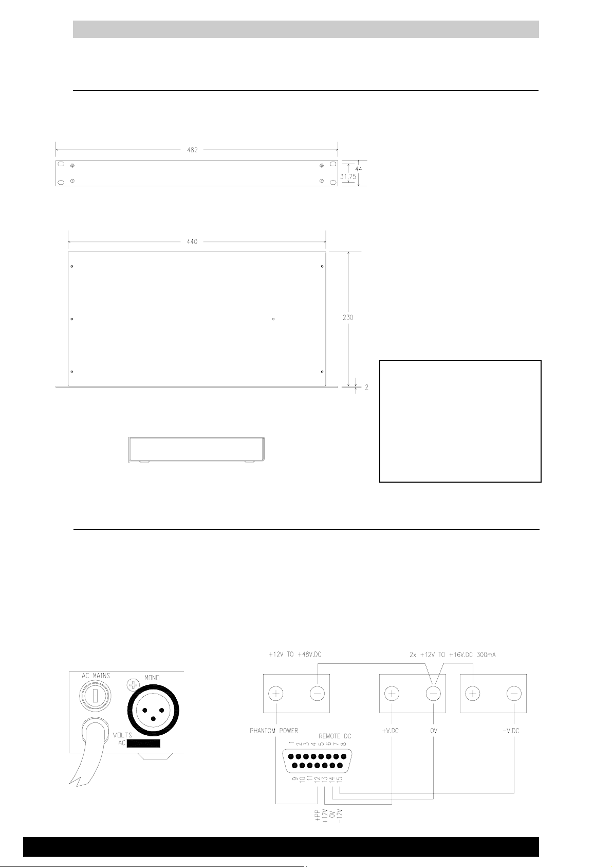
Width ............... 19.0" standard 19" rack ........ (540mm)
Height ............. 1.75" 1U rack space ............. (130mm)
Depth .............. 10.3" ......................................... (390mm)
weight ............. 10lbs ................... (4.5kg)
packed ............ 11lbs................... (5kg)
CONSTRUCTION: All metal chassis.
Standard 19" rack mount in 1U space.
Removable top cover for calibration and service access.
Internal power supply unit with low radiation torroidal transformer.
SPECIFICATION
FREQUENCY RESPONSE: 20Hz to 30kHz +0/-1dB
DISTORTION: THD 0.04% Line in to mix out at 1kHz
CROSSTALK: . Channel shutoff better than -90 dB at 1kHz
Channel pan better than -75 dB at 1kHz
Interchannel better than -80 dB at 1kHz
NOISE: ............ 22Hz to 22kHz
MIC EIN -128 dB into 150 ohms
LINE pre-amp at 0dB -89 dBu
MIX noise -80 dBu
POWER REQUIREMENTS: 50/60Hz 25VA max
Mains voltage factory set for local requirements.
Mains input protection fuse ......... T315mA (220-240V)
T630mA (100-120V)
EMERGENCY DC POWER BACKUP:
External DC power supply or batteries.
+/-12 to 16VDC at 300mA
+12 to +48VDC microphone phantom power.
PHANTOM POWER: +48V DC
Global +48V ON switch, individual channel disable links.
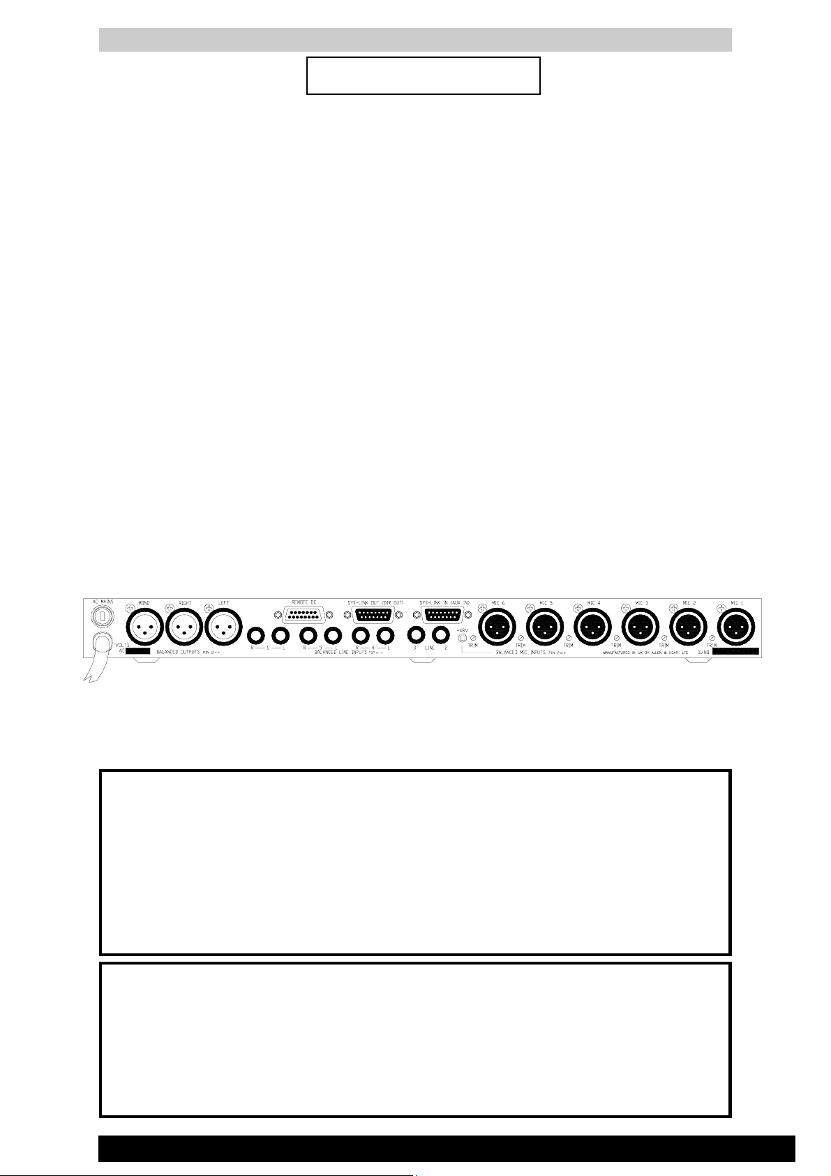
CONNECTIONS
INPUTS:
MIC IN ............................ XLR ........................... pin 2 hot, 3 cold balanced ........ 2k ohms .......... variable -55 to -12dBu
....................................... LINE (pad selected) .. pin 2 hot, 3 cold balanced ........ 10k ohms ........ variable -35 to +8dBu
MONO LINE IN .............. 1/4" JACK .................. tip hot, ring cold balanced ........ 10k ohms ........ -10dBV, 0dBu, +4dBu
STEREO LINE IN .......... 1/4" JACKS ............... tip hot, ring cold balanced ........ 10k ohms ........ -10dBV, 0dBu, +4dBu
AUX IN (SYS-LINK) ....... 15way D female ........ unbalanced ............................... 10k ohms ........ -2dBu
ALARM IN (SYS-LINK) .. 15way D female ........ unbalanced ............................... 10k ohms ........ -2dBu
ALARM DC (SYS-LINK) 15way D female ........ opto-coupled ................ link to 0V to enable
REMOTE VCA DC IN .... 15way D male .................................................. +10V = level max, 0V = channel off
BACKUP DC IN ............. 15way D male ........... main supply +/-12 to +/-16V DC phantom power +12 to +48V DC
OUTPUTS:
L, R, M OUT .................. XLR ........................... pin 2 hot, 3 cold balanced ........ 50 ohms ..........-10dBV, 0dBu, +4dBu
DIRECT (SYS-LINK) ..... 15way D female ........ unbalanced ............................... 50 ohms .......... -2dBu
L, R, M (SYS-LINK) .......15way D female ........ unbalanced ............................... 50 ohms .......... -2dBu
ALARM OUT (SYS-LINK) 15way D female ...... unbalanced ............................... 50 ohms ..........-2dBu
ALARM DC (SYS-LINK) 15way D female ........ opto-coupled ............................. link to 0V to enable
HEADPHONES OUT ..... 1/4" jack .................... tip L, ring R .................. for stereo headphones 8 to 400 ohms
REMOTE VCA DC REF 15way D male .................................................. +10V, 0V reference voltage for remote VCA control
USER GUIDE
5
Page 9
GR1
INSTALLATION
The GR1 fits into a 1U space in a standard 19" rack system. Alternatively the unit may be mounted into a cabinet
or plinth, or simply used free standing.
Dimensions shown are case size in
millimeters. Allow extra space as necessary for the front controls (add
26mm) and for the rear connectors.
Mount the console using 2x M6 bolts
each side for maximum strength. These
should be provided by the supplier of
the rack kit.
The rack should allow a minimum side
to side opening of 445mm.
Provision should be provided for removal of the top cover for access to the
internal configuration links.
CONNECTING POWER
A 1.7 meter long captive power cord with fitted plug
connects the GR1 to mains power. Check that the rear
panel indicates the correct setting for the local mains
supply, and that the correct mains plug is fitted. The
unit may be supplied wired for 100, 110, 120, 220, or
240V.AC. The rear panel mains protection fuse is a
standard 20x5mm antisurge type T315mA for 220240V or T630mA for 100-120V.AC.
PRECAUTION !
TO AVOID DAMAGE TO THE
INTERNAL ASSEMBLIES DO NOT
FIT SCREWS THROUGH SIDES
OR UNDERSIDE OF THE
CONSOLE. SECURE TO
EXTERNAL BRACKETS OR
FITTINGS THROUGH THE FRONT
PANEL RACK MOUNTING HOLES.
An emergency DC backup supply may be connected
so that the unit remains powered in the event of a
mains supply failure. This switches in automatically
when the internal DC supply voltages fall below the
level of the connected backup source. The front panel
ON indicator always shows when the unit is powered
either from mains or the backup supply.
DC BACKUP SUPPLIES
MAINS INPUT
6
USER GUIDE
Page 10
GR1
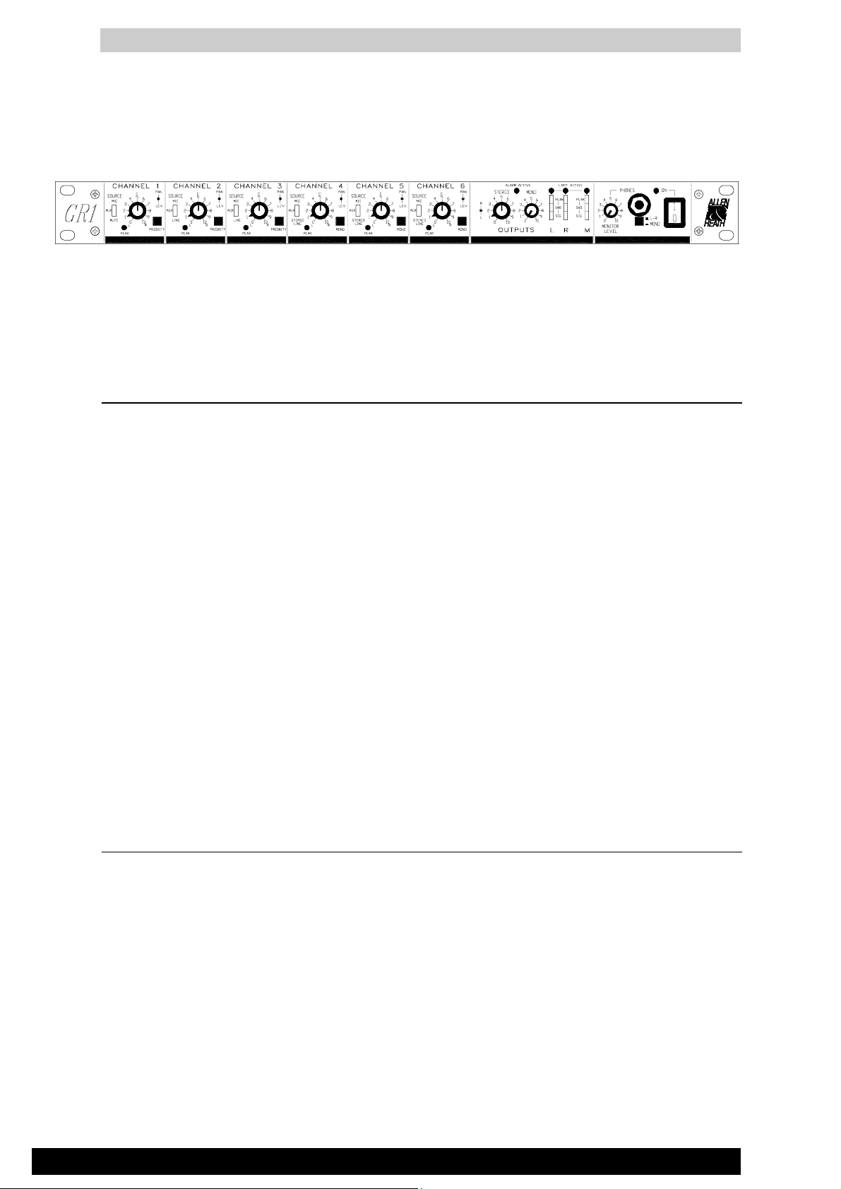
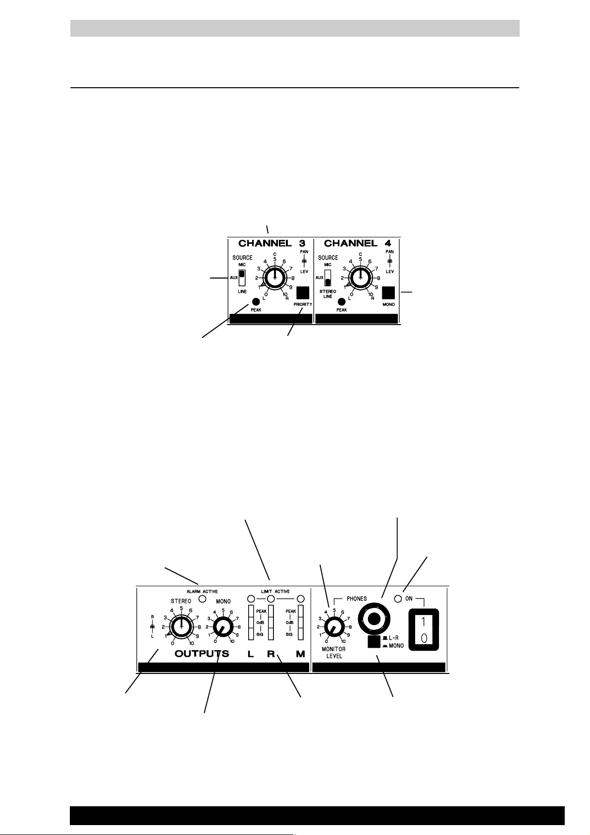
CONTROL FUNCTION
input section
SOURCE
The 3 way lever switch
selects either MIC,
AUX(OFF) or LINE inputs.
LEV & PAN
The top control adjusts the signal
level to the L, R, & M mix. The
lower control adjusts the position
in the stereo image. In the centre
click position, the L & R have
equal signal levels.
MONO
Selecting mono
combines the AUX
or LINE left & right
input signals.
PEAK
The peak indicator
illuminates when the
channel signal approaches
overload.
master section
LIMIT ACTIVE
Indicators illuminate when
compressor/limiters are active.
ALARM ACTIVE
Indicates the
alarm status of
the unit.
PRIORITY
Selecting priority on a
channel reduces the signal
levels of the other
channels.
PHONES
For headphone monitoring
the main output signals.
MONITOR LEVEL
Adjusts the PHONES
signal level .
ON
Indicates power to the
unit either AC mains or
external DC in.
STEREO
Adjusts the output
level of the main
L & R signals.
USER GUIDE
MONO
Adjusts the output
level of the mono
signal.
METERS
Used for signal
level checking.
L-R / MONO
Selects the
PHONES signal
source.
7
Page 11
CONFIGURATION
Remove the 6 crosshead screws securing the
top cover to the chassis. Lift off the cover to
gain access to the options. Apply caution if
powering the unit with the cover removed.
GR1
The GR1 offers unique flexibility in its ability to be configured to satisfy the exact requirements of each installation.
This is done by setting internal jumper links and calibration trimmers which determine the operating levels, signal
routing, and mode of operation of the ducking, alarm and compressor/limiter systems. These are accessed by
removing the top cover. The option link layout is shown above and in the system block diagram. Once installed the
settings become tamperproof and only the front panel controls are available to the user making the unit extremely
easy to operate.
Configuration should only be carried out by a competent installation engineer. Apply caution when powering the
unit with the top cover removed. Only the compressor/limiter threshold trims may need adjustment with power
applied. The following pages detail the installation options.
8
USER GUIDE
Page 12
GR1
EARTHING THE AUDIO SYSTEM
The chassis is connected to mains earth via the power cord. FOR SAFETY REASONS NEVER REMOVE THE
EARTH WIRE FROM THE MAINS PLUG.
Audio 0V is connected to mains earth
by the internal ground lift link op-
Multiple earth paths cause
earth (ground) loops which
may result in audible hum
and interference. These may
be avoided by making sure
that there is only one path to
earth from each piece of
equipment. An internal link
option is available for each
XLR output to disconnect
0V from the pin 1 cable
screen if necessary.
tion. Selecting ground lift disconnects 0V from the chassis (mains)
earth. This avoids ground loops in
situations where the chassis metalwork is in physical contact with another path to earth, (often the case in
19" rack installations), or if audio 0V
connects to mains earth elsewhere in
the system.
Shown ground linked
Shown ground lifted
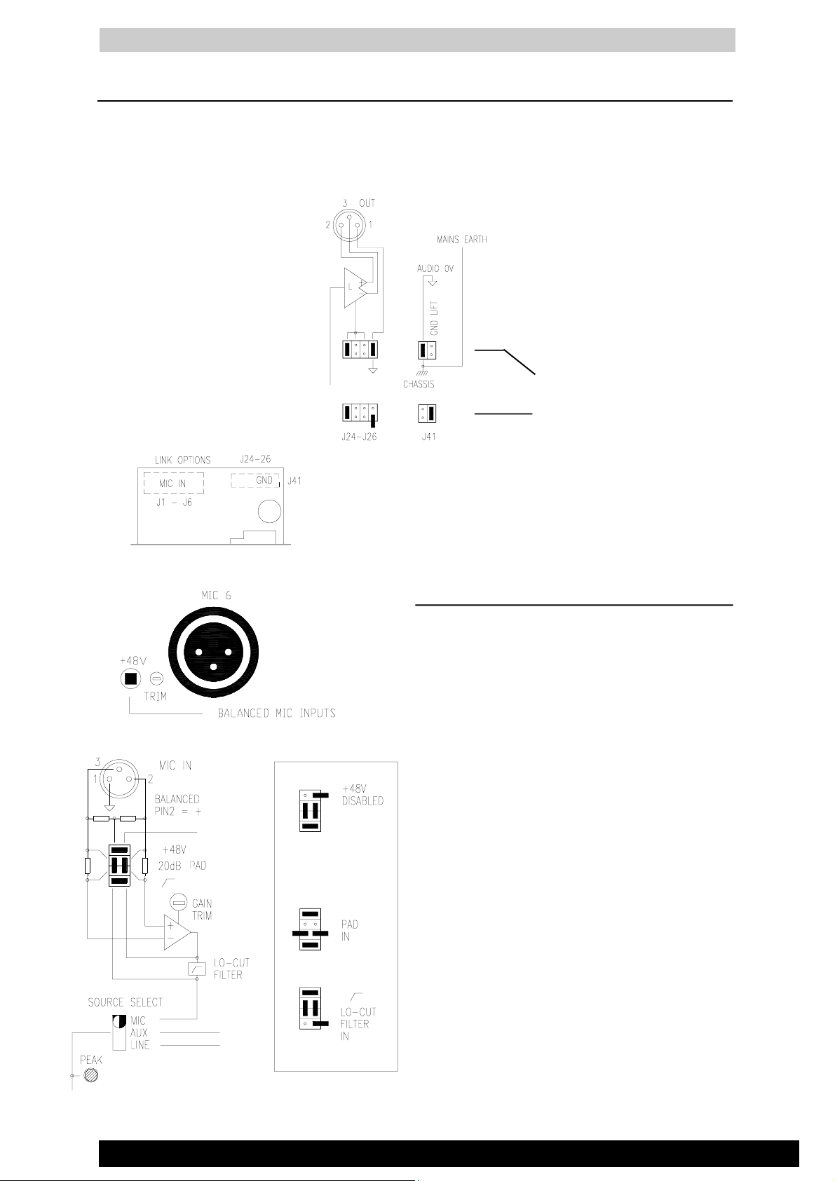
MIC INPUTS
6 electronically balanced XLR inputs each with a high
performance pre-amplifier and option links:
GAIN CALIBRATION TRIMMER
20-turn preset trimmer accessable with a trim tool or small
screwdriver through the rear panel. Matches a wide range
of microphone levels to the operating level of the unit.
Adjust with the channel level control fully clockwise for
an output meter reading averaging '0dB'. Reduce the trim
level if the channel PEAK indicators flash.
OPTION LINK - +48V PHANTOM POWER DISABLE
Remove link (set on one pin) to disable the internal +48V
phantom power supply from the XLR. Always disable
+48V when connecting to non-phantom powered microphone or line level sources. The rear panel +48V switch
turns on phantom power to all enabled XLR inputs when
pressed.
OPTION LINK - 20dB PAD
Remove 2 links (set on one pin) to enable the 20dB
attenuator pad when connecting to high output microphones or mono line level sources.
OPTION LINK - LO-CUT FILTER
Remove link (set on one pin) to enable the lo-cut filter to
reduce low frequency interference such as microphone
proximity noise, rumble and hum. This reduces frequencies below 70Hz.
USER GUIDE
9
Page 13
GR1
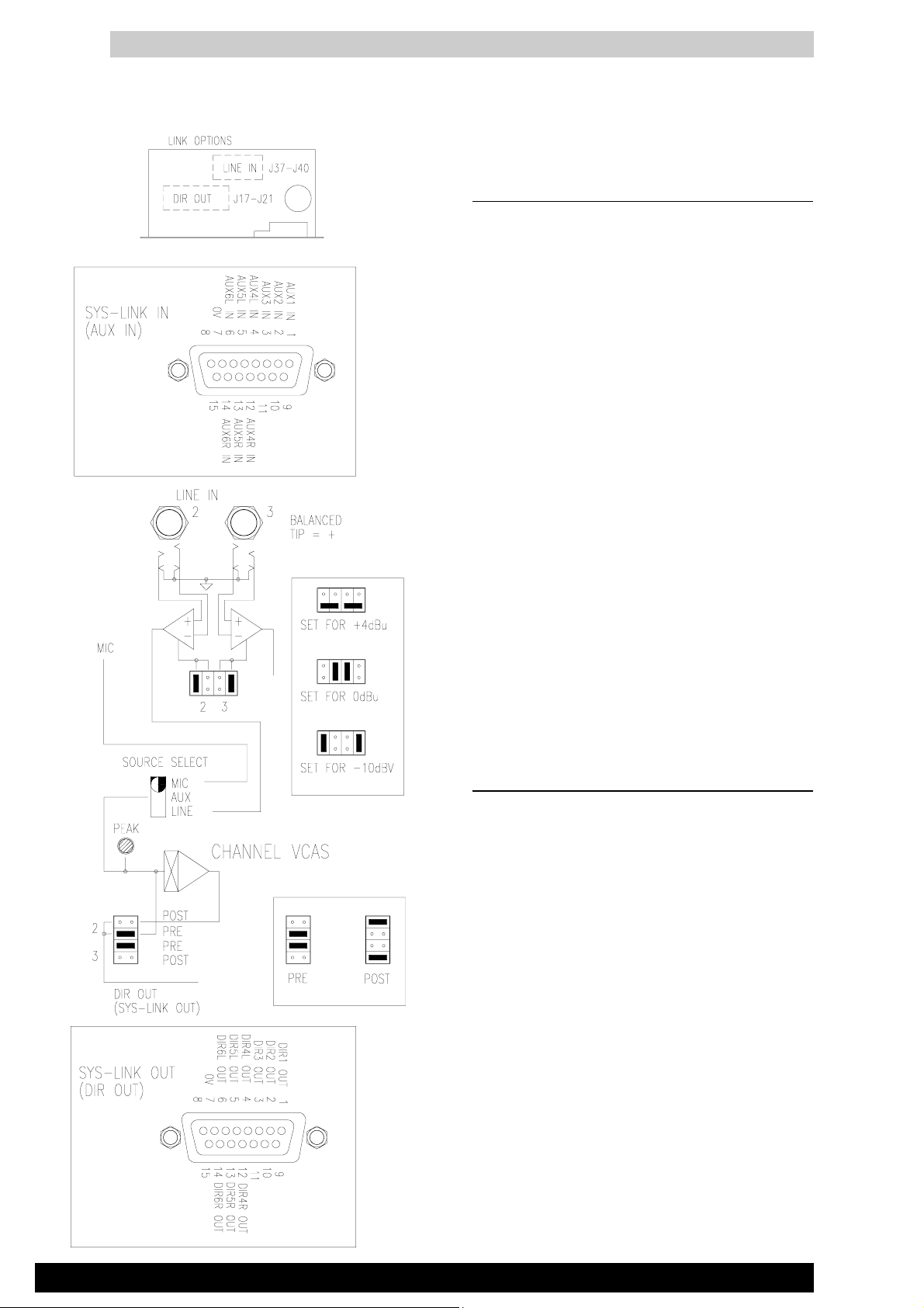
LINE INPUTS
MONO AND STEREO LINE INPUTS
2 Mono and 3 stereo electronically balanced line inputs
are available on 1/4" jack sockets. The stereo inputs
provide individual sockets for left and right inputs.
OPTION LINKS - LINE INPUT LEVEL
Unbalanced sources may be plugged into these inputs.
The inputs may be individually internally set for one of
three standard operating levels by positioning the jumper
links as shown. Note that two line inputs are set on one
bank of links.
+4dBu (1.2Vrms) High level
0dBu (0.775Vrms) Line level
-10dBV (300mVrms) Low level
MONO AND STEREO AUX INPUTS
An additional 2 mono and 3 stereo unbalanced line level
AUX inputs are available on the SYS-LINK IN connector. These operate at -2dBu (600mVrms). The AUX
inputs may be used for extra line inputs switchable from
the front panel, or for expansion of the system using
SYS-LINK.
CHANNEL DIRECT OUTPUTS
Line level unbalanced Direct Outputs for each input are
available on the SYS-LINK OUT connector. These
operate at -2dBu (600mVrms). The DIR outputs may be
used to feed additional zones, monitors, recording devices etc, or to expand the system using SYS-LINK.
OPTION LINKS - PRE/POST DIRECT OUTPUTS
Each DIR output may be taken from the output of the
input pre-amplifer before (pre) or after (post) the channel level control. PRE may be used to feed the channel
signals to additional GR1 units for zone expansion, or for
signal monitoring. POST may be used for recording
feeds, effects sends etc. Two channels are set on one
bank of links. Note that the inner links set PRE and the
outer links set POST.
10
USER GUIDE
Page 14
GR1
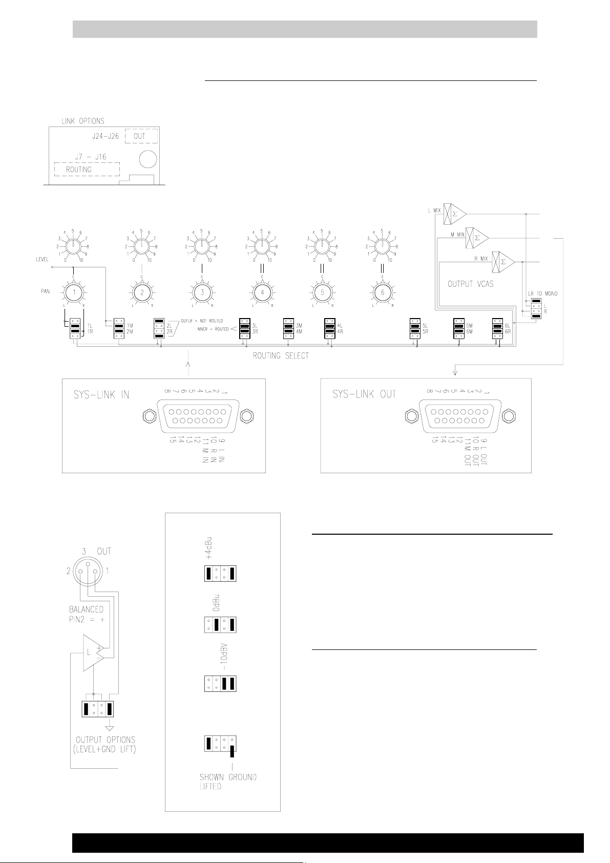
ROUTING THE CHANNELS TO THE OUTPUTS
Each of the 6 channels may be routed as required to a combination of the 3 outputs
L, R and M to feed up to 3 mono zones or one stereo and one mono zone. The L
and R post level outputs may also be routed to the M output for situations where a
L+R sum is required. Note that the channel inputs may be summed with L+R to
provide an independent mix based on the L and R outputs.
OPTION LINKS - CHANNEL ROUTING
Select the inner jumper links for routed signals, outer links for not routed.
L,R,M SYS-LINK INPUTS/OUTPUTS
The L, R and M outputs are also available on the SYS-LINK
OUT connector. Inputs are available on the SYS-LINK IN
connector. These operate unbalanced at -2dBu (600mVrms)
and may be used as additional mix inputs and outputs or to
expand the system using SYS-LINK.
MAIN OUTPUTS
The main L, R and M outputs are available on electronically balanced line level 3-pin XLR male connectors.
OPTION LINKS - LINE OUTPUT LEVEL
These may be individually set for one of three standard
operating levels by positioning the jumper links as
shown. +4dBu (1.2Vrms) High level
0dBu (0.775Vrms) Line level
-10dBV (300mVrms) Low level
OPTION LINKS - OUTPUT XLR GROUND LIFT
Set the jumper as shown to connect or disable XLR pin
1 from audio 0V for optimum system grounding to avoid
problems with ground loops.
USER GUIDE
11
Page 15
GR1
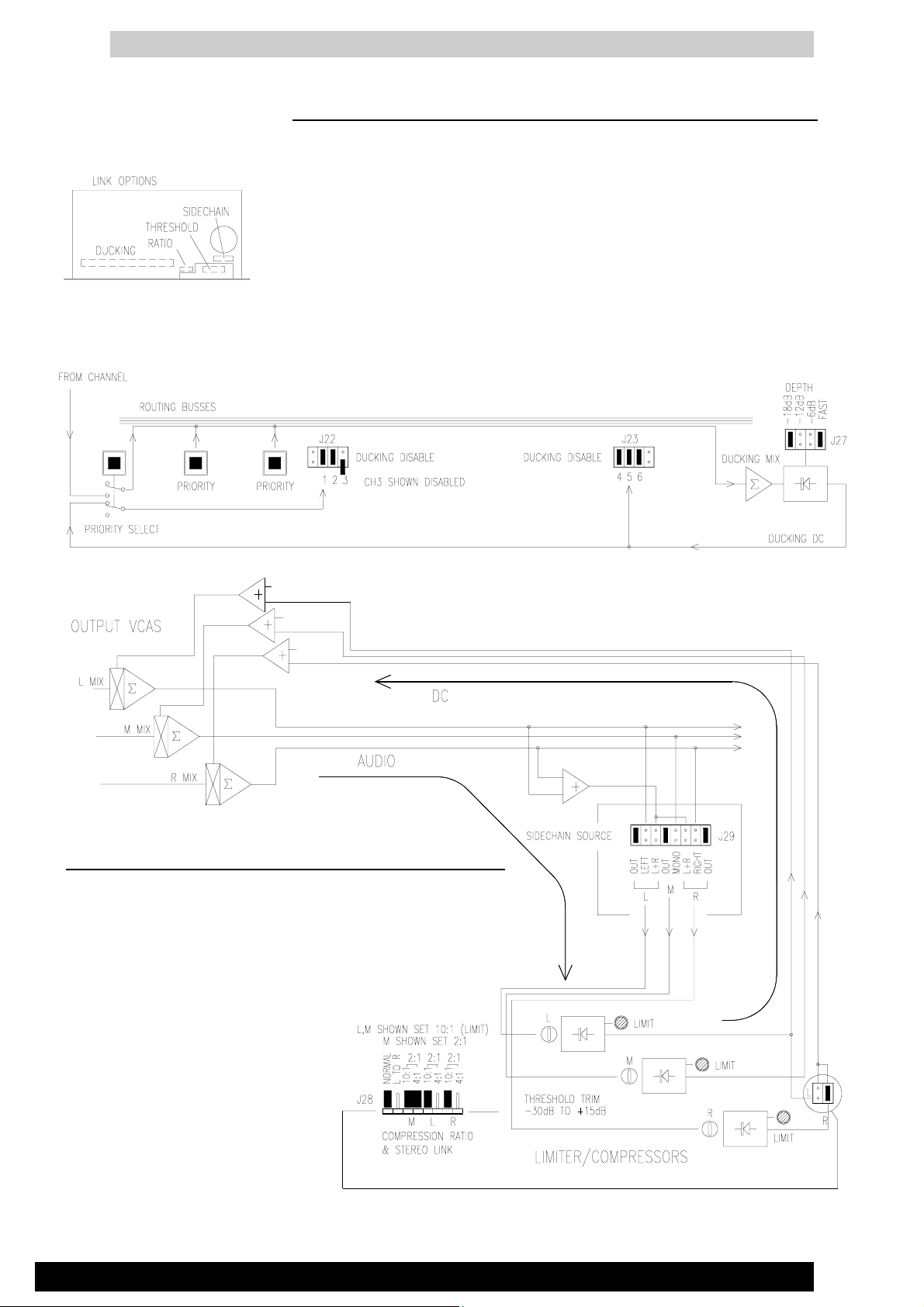
PRIORITY DUCKING SYSTEM
The GR1 offers a flexible ducking system that allows one or a combination of the 3
mono channels to duck (override) the level of the other channels by reducing their level
by a pre-determined amount. For example this may be used for voiceover anouncements
where the background music is dimmed by the microphone signal level. The channel
or channels that cause the ducking are selected by pressing the front panel PRIORITY
switches. The selected channels are themselves disabled from ducking when this
switch is pressed. Any channel may be disabled from ducking by setting the internal
jumper link.
OPTION LINKS - INDIVIDUAL DUCKING DISABLE FOR CH1 TO 6
OPTION LINKS - DUCKING DEPTH AND RELEASE TIME
Select the required amount of ducking effect: -6dB, -12dB, -18dB. The time taken for
the ducked signal to return to normal level is set by the FAST/SLOW link.
COMPRESSOR / LIMITERS
Each of the 3 main outputs has a high performance compressor/limiter
which may be selected in or out of circuit to provide overload protection
(limiting) or signal dynamic range compression. These may be linked for
stereo operation. Each has a front panel LIMIT indicator that illuminates
when compression or limiting takes place.
OPTION LINKS - SIDECHAIN SOURCE
Selects the source that controls the limiter:
OUT, L(R,M), or L+R for stereo link.
OPTION LINKS - COMPRESSION RATIO
10:1 limiting - a level increase of
10dB causes only an output rise of
1dB above the threshold level.
4:1 hard compression
2:1 soft compression
OPTION LINKS - STEREO LINK
Set as 'L TO R' for stereo link.
OPTION TRIMMER - THRESHOLD LEVEL
Sets the level at which compression or limiting occurs. From -30dB to +15dB.
12
USER GUIDE
Page 16

GR1
REMOTE CONTROL OF THE LEVELS
Each of the 6 channels and the main L,R and M outputs are fed through high
performance VCA (voltage controlled amplifier) circuits. These are controlled
individually either by the front panel level controls or by external DC voltages
connected to the REMOTE DC connector according to the setting of the internal
jumper links as shown below.
Control Voltages are:
+10V DC = channel fully on
0V = channel off
A buffered +10V DC reference voltage is
provided on the REMOTE DC connector.
This may be connected to a potentiometer for
remote level control. The recommended
potentiomenter is 10K ohms reverse (antilog)
logarithmic.
Use screened cable to minimise interference
pickup.
NOTE: Any references to control voltages of
0V to -9V should be substituted with the
above.
LINK OPTIONS
INT/EXT DC CONTROL
The inner links set internal front panel level
control, the outer links set external level
control.
+10V DC INT/EXT VOLTAGE
The +10V DC voltage can be derived internally or externally by setting the link on the
remote connector circuit board.
USER GUIDE
13
Page 17

ALARM OVERRIDE
To allow automatic control of the system by an alarm recording or emergency announcement the GR1 includes a comprehensive alarm override feature. When activated the front
panel ALARM ACTIVE LED lights and the 3 main outputs are automatically switched to
the selected alarm audio source. This is selected by internal jumper links to be the ALARM
AUDIO IN on the SYS-LINK IN connector or the local MIC 6 input.
The alarm system is activated when the opto-coupled ALARM DC connection is linked to
0V. This may be done by a switch or external logic system.
Control states are: +15V (open circuit) = normal output
0V (link to 0V) = alarm active
LINK OPTIONS - ALARM SOURCE
Selects either the external alarm input
or local MIC 6 as the local alarm
source and feed to other GR1 units
within a SYS-LINK connected system.
GR1
Connect a nominal -2dBu line
level unbalanced signal to
ALARM IN
LINK OPTION - ALARM AUDIO TEST
An internal jumper may be set for
diagnostic testing of the alarm audio
source without activating the alarm
DC control. Audio may be routed to
the outputs for checking by selecting
CH1 MUTE position with the link set
to ALARM TEST.
14
The alarm signal is switched directly before the main outputs and is
not affected by the compressor/limiters or output level control. Combined with the automatic power backup feature this provides a
complete and foolproof emergency system.
USER GUIDE
Page 18

GR1
EXPANDING THE INPUTS WITH SYS-LINK
The number of input channels feeding the outputs may be expanded by connecting GR1 units together
using the SYS-LINK system. A single cable connects the L,R and M outputs of one unit to the buss
inputs of the next.
Use screened multiway cable connected as shown below to standard 15way D-type male connectors.
Do not interconnect the DIR OUTs to the AUX INs when linking L,R and M outputs. The example
shown below includes interconnection of the alarm override system so that one alarm source controls
all units simultaneously.
For output level control at the master unit only disable the L,R and M
output level controls on the slave units by removing the INT/EXT links
J35 and J36.
USER GUIDE
15
Page 19

EXPANDING THE OUTPUTS WITH SYS-LINK
The number of outputs may be expanded by connecting GR1 units together using the SYS-LINK
system. This may be used to provide more zone feeds from the 6 input channels. A single cable connects
the 6 channel DIR outputs of one unit to the AUX inputs of the next.
Use screened multiway cable connected as shown below to standard 15way D-type male connectors.
Do not interconnect the L,R and M outputs to the L,R and M buss inputs when linking the channels.
The example shown below includes interconnection of the alarm override system so that one alarm
source controls all units simultaneously.
GR1
16
Set the slave unit channel selector switches to 'AUX'. This selects the
corresponding signal from the master unit. The DIR OUT pre/post links
J17 - J21 should be set to the 'pre' position so that the local level controls
do not affect the feeds to the other units.
USER GUIDE
Page 20

GR1
USER GUIDE
17
Page 21

Page 22

Page 23

Page 24

Page 25

Page 26

Page 27

Page 28

SECTION C
TECHNICAL DIAGRAMS
This section includes the technical diagrams
and illustrations
C
R1SM1
Section C - 1
ALLEN & HEATH
Page 29

TECHNICAL BULLETIN
Attention Service Departments
REF.
Title:
File with GR1 Service Manual
GR1_01
ISSUE 3 PCB MODIFICATIONS
Issue No.
1
Date:
25-11-94
Page:
Authorised:
The following applies to all GR1 units with Issue 3 PCBs (AG2041 Issue 3).
1) GR1 PCB Issue 3
The issue 3 version of the GR1 PCB (AG2041 Issue 3) has a number of minor modifications.
These are:
i: SYS-LINK OUT L and M are swopped. This is corrected by crossing over two resistors
R643 and R645.
ii: The meter PCB is too far back from the front panel. This is corrected by spacing the
PCB 1.6mm forward on the connector pins.
iii: The MONO and PHONES level controls are too far back from the front panel. This
is corrected by placing washers over the control shafts.
iv: The text legend on link J22 is in the wrong position. The text should be moved one
position to the right.
1
of:
I Mc B
1
is
1 2 3
should be
1 2 3
All of these errors have been corrected for the issue 4 version of the PCB.
ALLEN & HEATH
Section C - 2
R1SM1
Page 30

Front Panel Assembly
Rear Panel Assembly
R1SM1
Section C - 3
ALLEN & HEATH
Page 31

USER GUIDE
17
Page 32

Page 33

Page 34

Page 35

Page 36

Page 37

Page 38

Page 39

Page 40

Page 41

Page 42

Page 43

Page 44

Page 45

Page 46

Page 47

Page 48

 Loading...