

Page 1
DIGITAL MIXING SYSTEM
Screen Reference Guide
For GLD firmware Version V1.4
Check the Allen & Heath web site for the latest version available
Also read the GLD User Guide AP8561
Page 2

1. Contents
1. Contents........................................................................ 2
1. Power Up Screens ........................................................ 3
2. Home Screen ................................................................ 4
2.1 Home page ............................................................... 4
2.2 Users Login page ..................................................... 5
2.3 Quick Start page ...................................................... 5
3. Processing Screen ....................................................... 6
3.1 Name and Colour keypad ........................................ 6
3.2 Overview page – Input Channel ............................... 6
3.3 Overview page – Mix Channel ................................. 7
3.4 Overview page – FX Send or Return ....................... 7
3.5 Channel Libraries ..................................................... 8
3.6 Preamp page ............................................................ 8
3.7 Preamp Option - Gain/Trim on Surface ................... 9
3.8 Mix Ext In source ...................................................... 9
3.9 Noise Gate page ....................................................10
3.10 Insert page .........................................................10
3.11 PEQ page ...........................................................10
3.12 GEQ page ..........................................................11
3.13 Compressor page ..............................................13
3.14 Delay page .........................................................13
3.15 Routing Page – Input Channel view ..................14
3.16 Routing page – Mix Master view........................15
3.17 Routing page – DCA Master ..............................16
4. Meters Screen .............................................................17
4.1 Input Meters page ..................................................17
4.2 FX and Mix Meters pages ......................................17
4.3 Custom 1-4 Meters pages ......................................18
4.4 RTA .........................................................................18
5. FX Screen ...................................................................19
5.1 Front Panel view .....................................................19
5.2 Back Panel view .....................................................19
5.3 FX Libraries ............................................................20
5.4 FX Devices available ..............................................20
6. I/O Screen ...................................................................30
6.1 dSNAKE I/O page ..................................................30
6.2 dSNAKE EXPANDER page ....................................30
6.3 Surface / EXPANDER page ....................................30
6.4 I/O Port Inputs page ...............................................31
6.5 I/O Port Outputs page ............................................31
6.6 Monitor Outputs page ............................................32
6.7 MMO card in the I/O Port .......................................32
7. Scenes Screen............................................................33
7.1 Scene Manager page .............................................33
7.2 Scene Crossfade ................................................... 34
7.3 Embedded Scene Recall ....................................... 34
7.4 Scene Recall Filter page ........................................ 35
7.5 Cue List Editor page .............................................. 36
7.6 Scene Safes page ................................................. 37
8. Ganging Screen ......................................................... 38
9. Setup Screen – Audio ................................................ 39
9.1 PAFL Setup page ................................................... 39
9.2 Talkback Setup page ............................................. 39
9.3 SigGen page .......................................................... 40
9.4 USB Audio page .................................................... 41
9.5 Audio Sync Setup page ......................................... 42
9.6 I/O Port Setup page ............................................... 42
10. Setup Screen – Control ......................................... 43
10.1 Strip Assign Setup page ................................... 43
10.2 MIDI Strips ......................................................... 43
10.3 Name & Colour Setup page .............................. 45
10.4 SoftKeys Setup page ........................................ 45
10.5 Dimmer page ..................................................... 46
10.6 Surface Preferences Setup page ...................... 47
10.7 MIDI Setup page ............................................... 47
11. Setup Screen – Memory ........................................ 48
11.1 Show Manager page ......................................... 48
11.2 Template Shows as a starting point ................. 48
11.3 Library Manager page ....................................... 49
12. Setup Screen – Config........................................... 50
12.1 Mixer Configuration Setup page ....................... 50
12.2 Network Setup page ......................................... 51
12.3 User Profiles Setup page .................................. 51
13. Setup Screen – Utility ............................................ 53
13.1 Diagnostics page .............................................. 53
13.2 Date/Time Setup page ...................................... 53
13.3 Calibration Setup page ..................................... 53
13.4 Firmware Setup page ........................................ 54
14. Resetting the GLD.................................................. 55
GLD Touch Screen Reference V1.4 – Issue 1 2 ALLEN&HEATH
Page 3
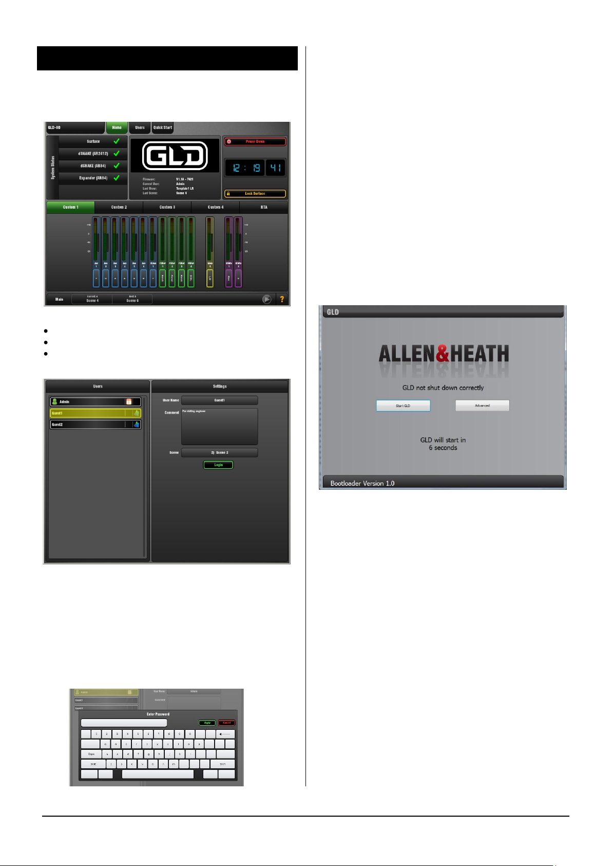
1. Power Up Screens
The Home screen will appear on power up If no password
is set.
The Login screen will appear when you:
Power up when the current User has a password set
Unlock the surface when a password is set
Change user from the Home screen
User Scene – If a User Scene is set it is recalled
automatically on login when the user is changed. It does
not recall when the same user logs in, or when the system
is powered up again while the same user is current.
A User Scene can be set by Admin to ensure a predetermined layout and starting point loads when a different
user logs in.
Permissions – Access to selected functions and
parameters can be restricted for each User. This is
configured by Admin using the Setup screen.
Not Shut Down Correctly reminder screen
If the GLD was last switched off without it being first shut
down using the Home screen Power Down button this
screen will appear on power up. The GLD will continue to
boot after a 10 second count down. Choose to start
immediately using the Start GLD button, or go to the
Advanced page if you wish to fully reset the system.
Users List
The list shows available Users. The Admin User is always
displayed. Up to 9 other Users that have been made ‘Active’
by Admin will also display in the list. Icons show if the User
has a password or User Scene set.
Password – If one is set it needs to be entered using the
screen keypad when the user logs in.
GLD Touch Screen Reference V1.4 – Issue 1 3 ALLEN&HEATH
Page 4
2. Home Screen
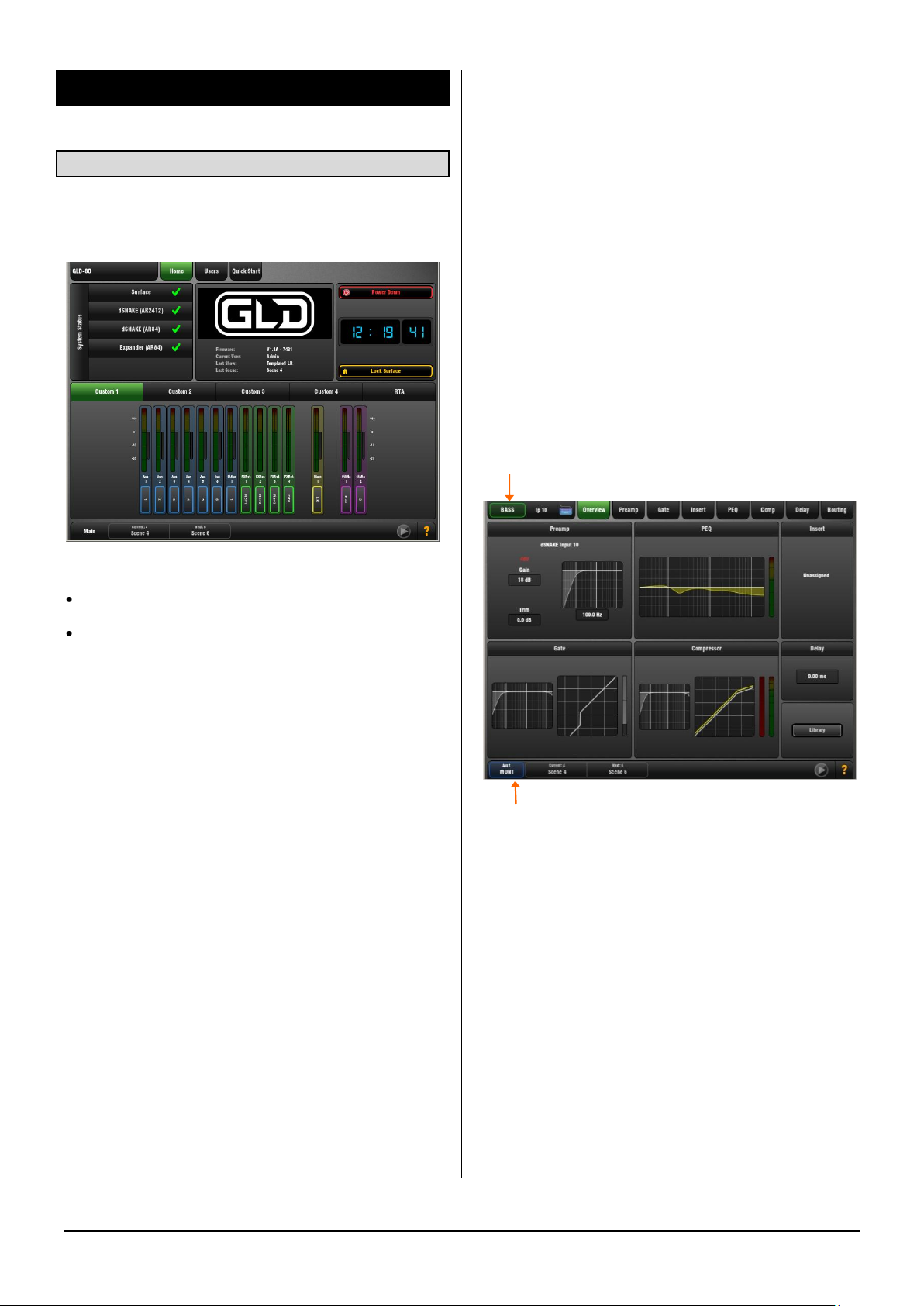
2.1 Home page
This is the main Home screen. It displays after power up. It
also displays when the screen Processing key is active and
the active Sel key is turned off.
To safely Power Down the GLD system - Touch the
Power Down button, confirm, and then switch power off.
Failure to power down correctly may result in parameter
changes made up to 30 seconds before power is removed
becoming lost.
Lock Surface - Touch the Lock Surface button and Yes in
the confirmation popup to lock the surface controls.
Parameters will not be changed if the surface controls are
moved while locked, for example when left unattended.
Touch the screen again to unlock the surface and return the
controls to their previous setting.
Note If a password is set for the current user then this must
be entered when the user locks or unlocks the surface.
Help Manual – GLD has a built-in Help manual. Touch the
? in the status bar to open the Help for the current page.
Current status display:
Active Processing – Displays the Name and Colour for the
channel currently selected using a fader strip Sel key is
displayed at the top left of the screen.
To return to the Home screen at any time:
Turn off the active Sel key while in a Processing screen,
or
Press the Processing key next to the touch screen
once if no Sel key is active, or twice a Sel key is active.
Page tabs – Touch a tab at the top of any screen to open
its associated page.
GLD information – The centre section of the Home page
displays Firmware version, current User logged in, and last
Scene and Show recalled.
System Status - Displays a list of connected AudioRacks. A
green tick indicates system good. If a blue circle appears
touch the box to open a window for information about the
event logged, for example a QOS (cable) error. Touch the
box again to close the window.
Custom Meters 1-4 – These screens can be assigned by
the user with a selection of up to 16 meters. They can be
blank if no meters have been assigned.
RTA – The 31-band 1/3 octave Real Time Analyser can be
displayed. Its source is the current PAFL monitor selection.
Note The RTA can also be viewed on the mix GEQ page
and on the fader strip meters while in GEQ Fader Flip
mode.
Clock - Shows the time in hours, minutes, seconds. Set
this using the Setup / Utility / Date/Time screen.
Active Mix – Displays the Name and Colour for the Mix
currently selected using a fader strip Mix key is displayed at
the bottom left of the screen. When the Main (LR) mix is
active the status bar simply displays “Main”.
Note Be aware of which mix is currently active while you
are mixing. It is good practice to turn off the Mix key to
return to the main mix once you have finished adjusting a
mix, for example an Aux or FX send.
Current and Next Scene – The last Scene recalled and the
Scene highlighted in the list ready to be recalled are
displayed in the status bar. When the Scene is recalled its
name briefly flashes green to confirm the action.
USB playback/record status – An icon at the bottom right
of the screen lights blue while playing back and red while
recording. Touch the icon to open the USB Audio page.
Yellow triangle error indicator – Touch the yellow triangle
to view the Event Log.
GLD Touch Screen Reference V1.4 – Issue 1 4 ALLEN&HEATH
Page 5
Quick Start Mixing Guide
For the new user or guest engineer to start mixing with GLD. It assumes a mixer already configured for the show. To learn
more about configuration, memories and advanced functions read the on-screen Help Manual and User Guide AP8561.
Mix
IP 1 IP 2 IP 3 IP 4 IP 5 IP 6 IP 7 IP 8 Aux1 Aux2
LR
Channel faders Master faders
+ press Mix
ON
IP 1 IP 2 IP 3 IP 4 IP 5 IP 6 IP 7 IP 8 Aux1
Aux2
+ press Mix Assign RoutingONall
+ press Sel Pre/Post
PRE
IP 6 IP 7 IP 8 Aux1 Aux2
ONPRE
Mix
All sends to one master Master faders Channel faders
Aux3
Aux3 Aux3
Sel
Mix
Sel
Mix
Preamp PEQ
LF
HPF GATE
Routing
LM HM HF
Gain
Normal mix mode (FOH)
Master Mix
Channel Mix
Assign Routing
Assign Routing
Pre/Post
Sel
Mix
www.allen-heath.com
all
Aux4 Aux4
Main Mix active
All sends from one input
Press Mix again to return to Main mix
view
view
Access Aux, FX, Matrix mix on faders
IP 4 IP 5 IP 6 IP 7 IP 8 Grp1 Grp2
+ press Mix all
DCA
Mix
DCA and Audio Group assign
Assign
DCA2
IP 5
IP 4
ON
DCA
Touch a parameter, adjust using rotary
St Aux 4
?
Check which Mix is currently selected
Channel Name
Aux
PRE
NAME
IP
St
DCA
Strip type
Channel is Safe
from Scene recall
Assigned to one or
more DCA groups
User-defined channel Name
GAIN
Select rotary function
Assignment Mix type Pre/Post send
Stereo
Channel assignment
to current Mix
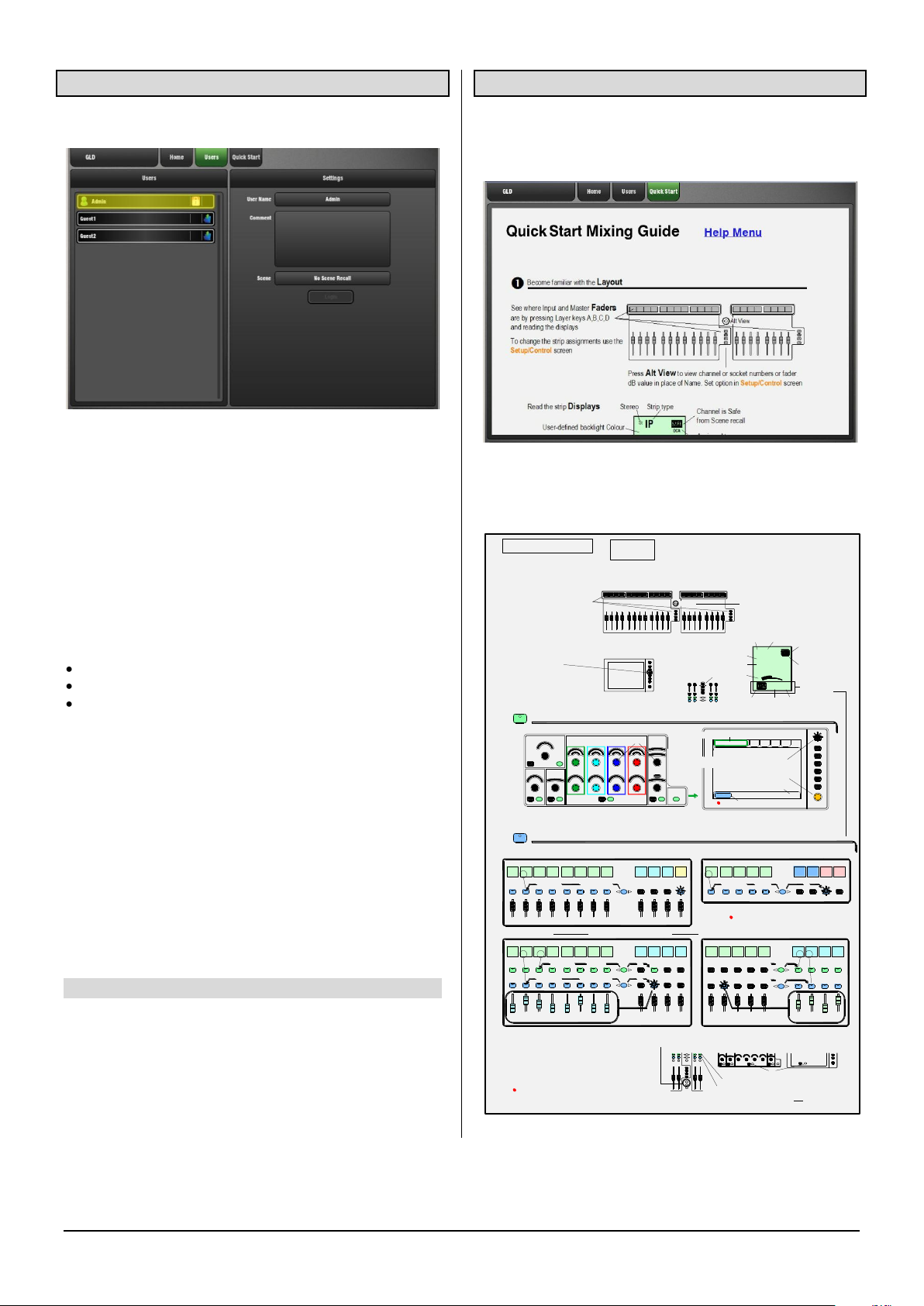
See where Input and Master Faders
are by pressing Layer keys A,B,C,D
and reading the displays
To change the socket assignments
touch and select from drop-down menu
See how the Sockets are patched
using the I/O screen.
Access the Channel and Mix processing
Access the Sends and Assignments
Touch to change Name and Colour
Access the FX
> To send to an FX - press FX master Mix
> To adjust FX parameters - press FX strip Sel
> To return to the mix use related FXret channel
To Link parameters eg, 2 channels for stereo keyboard
Use the Ganging screen. Choose attributes.
Ganging does not link the Gains or Trims.
To Copy parameters
> Hold down Copy and press the Sel or Mix key of the parameters to copy:
Sel
Sel
Sel = All channel processing (not Gain or Trim)
Mix = Sends and Assignments (not Pre/Post)
Surface or Screen Sel = Single processing block
Copy GEQ here
1
hold
down
hold
down
hold
down
hold
down
> Now hold down Paste and press the Sel or Mix key of the strip to paste to
For parameters on screen Processing must be active
push for second fuction
Opens on-screen Help Manual
User-defined backlight Colour
To change the strip assignments use the
Setup/Control screen
Press Alt View to view channel or socket
numbers or fader dB value in place of Name.
Set option in Setup/Control screen
Alt View
I/O
For GEQ on faders press GEQ Fader Flip - Master on last fader. RTA on strip meters. RTA follows current selected PAFL
2.2 Users Login page
Open this page to log in as a different User.
The system Administrator can set up to 9 User Profiles to
protect settings and reduce operator error by restricting
access to certain functions for different users.
The list shows available Users. These can be configured in
the Setup / Config / User Profiles screen. The Admin User
is always displayed. Only other Users that have been made
‘Active’ by Admin will display in the Users page. The list
displays if the User has a password or User Scene set.
Password – If one is set it needs to be entered using the
screen keypad when:
The User logs in using this screen
The GLD is powered up
The User locks or unlocks the surface
User Scene – The folder icon in the list shows if a User
Scene is set. The window on the right displays which Scene
is set for the User highlighted in the list.
Note The User Scene, if one is set, is recalled
automatically on login when the User is changed. It does
not recall when the same User logs in, or when the system
is powered down and up again while the same user is
current.
Permissions – Access to selected functions and
parameters can be restricted for each User. These are
configured by Admin.
2.3 Quick Start page
Opens a Quick Start sheet to help the new user or guest
engineer learn in just a few minutes how to mix their show
using GLD.
Swipe up and down the screen to scroll through the page.
Touch Help Menu to open the list of additional Help topics.
GLD Touch Screen Reference V1.4 – Issue 1 5 ALLEN&HEATH
Page 6
Sel key and button PFL listen function
Press and hold any processing Sel key or screen Sel
button to listen to (PFL) the signal at that point in the
channel signal path. This interrupts the current PAFL
selection in the headphones and listen wedge/IEM
monitor. The option can be turned on or off using the
‘Disable PFL on Sel’ button in the Setup / Audio / PAFL
screen.
3. Processing Screen
3.1 Name and Colour keypad
Input channels, FX sends and returns, Mix masters and
DCA masters can each be given a Name and Colour using
the on-screen touch keypad. These display in the fader
bank LCD ‘virtual write-on strip’ and also on the screen
wherever the channel name is shown.
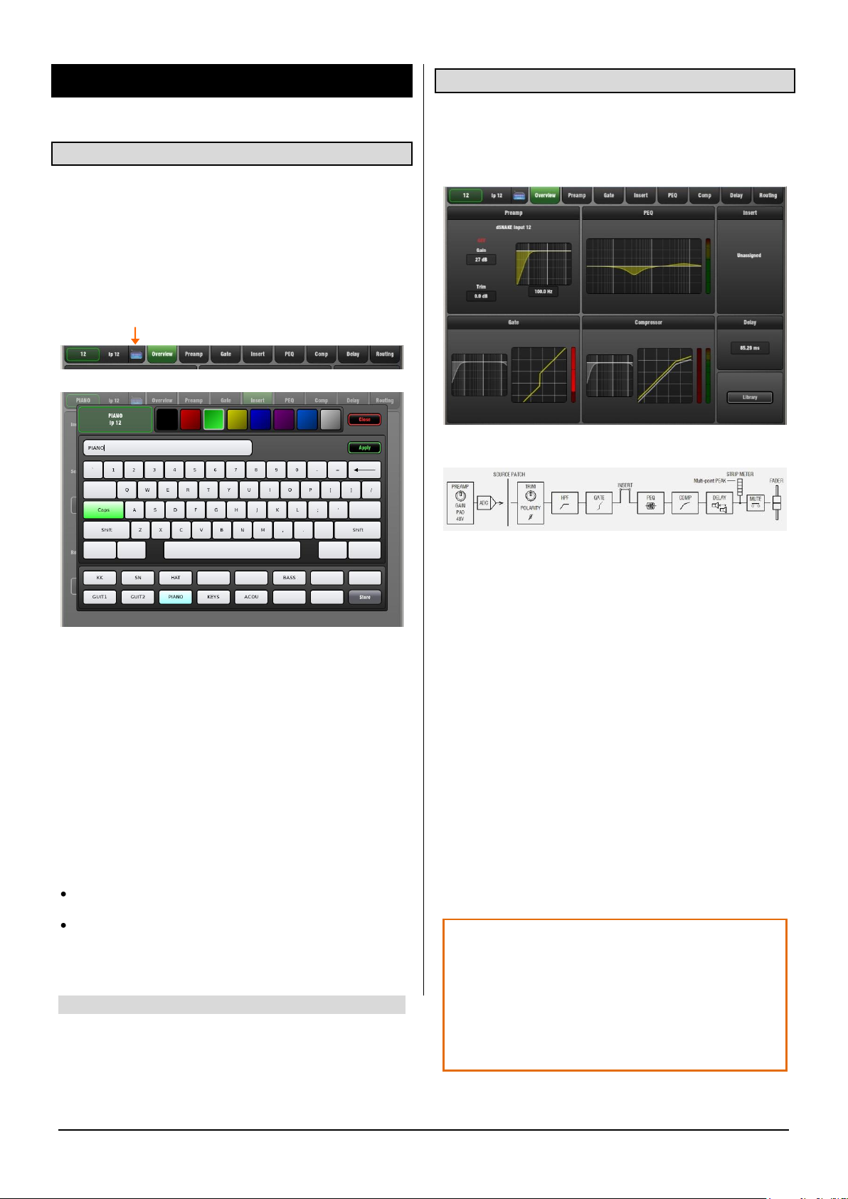
To open the on-board naming keypad touch the keyboard icon at the top left of the screen while in the Processing
screen with a fader strip Sel key active.
3.2 Overview page – Input Channel
Input Channel processing pages are accessed by pressing
an Input strip Sel key while the Processing screen is
selected. The Input Overview page provides a thumbnail
view of all processing for the selected input channel.
The signal flow for the Input Channel is:
Colour – Touch a colour box to instantly apply that colour
to the channel. 7 colours and off are available.
Name – Type in a name using the keypad. Use Caps and
Shift to access uppercase and special characters. Touch
Apply to accept the change or Close to shut the keypad
without accepting the change.
A name can have up to 8 characters.
Note 5 characters are displayed on the fader strip LCD.
Quick Names – Up to 15 names can be entered and stored
for instant access.
To store, type in a name, touch a Quick Name box and
touch Store.
To recall, touch a Quick Name box and touch Apply.
Quick Names are stored in Show memories.
Touch a tab at the top of the screen or touch a section to
open the related processing or routing window. EQ and
dynamics curves display yellow when switched In and grey
when switched Out.
The top left block shows Preamp and HPF. Icons show 48V
phantom power and Pol- polarity setting. The source
currently patched to the channel is also shown.
The Gate is available on input channels only.
Insert – Assignment and bypass status are shown.
Delay – Shows the setting for the selected input. For a view
of all Input Channel delays open the Delay page.
Library – The Input Channel Library is accessed from the
Overview page.
GLD Touch Screen Reference V1.4 – Issue 1 6 ALLEN&HEATH
Page 7
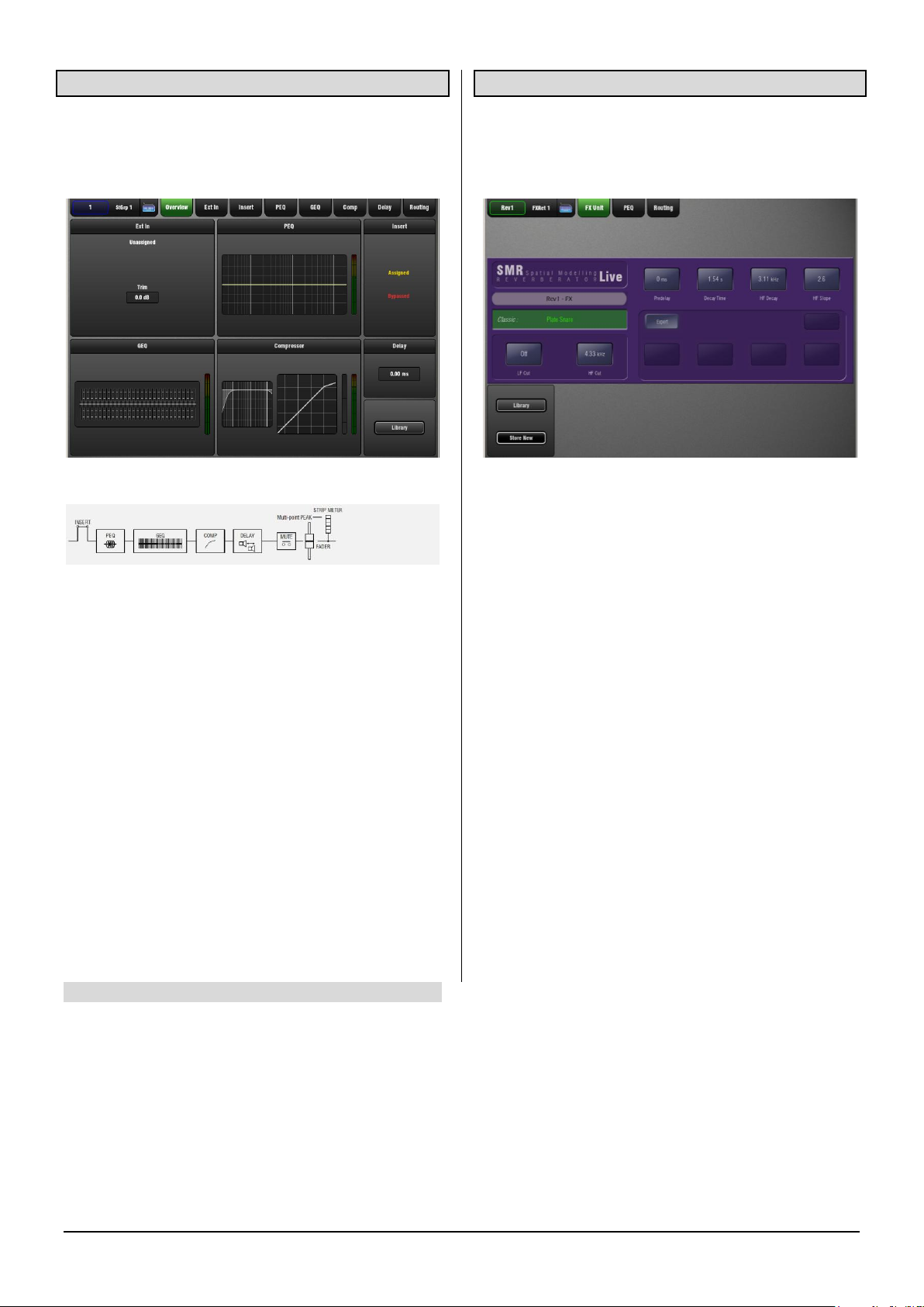
3.3 Overview page – Mix Channel
Mix processing pages are accessed by pressing a mix
master strip Sel key while the Processing screen is
selected. The Mix Overview page provides a thumbnail view
of all processing for the selected mix channel.
The signal flow for the Mix Channel is:
Touch a tab at the top of the screen or touch a section to
open the related processing or routing window. EQ and
dynamics curves display yellow when switched In and grey
when switched Out.
The top left block shows if a Preamp or other source has
been assigned as the External Input to the mix. Default is
none assigned. Trim affects the external input only.
The GEQ is available on mix channels only.
Insert – Assignment and bypass status are shown.
Delay – Shows the setting for the selected mix. For a view
of all Mix Channel delays open the Delay page.
Library – The Mix Channel Library is accessed from the
Overview page.
3.4 Overview page – FX Send or Return
FX processing pages are accessed by pressing an FX Send
or Return strip Sel key while the Processing screen is
selected. The page provides a thumbnail view of all
processing and parameters for the selected FX.
Touch the FX parameter controls and use the screen Rotary
to adjust values. Touch a tab at the top of the screen to
open the PEQ or routing window. The 4-band PEQ is
available within the FX Return strip.
Touch to highlight the FX preset name and use the Rotary
to scroll through the available presets for the FX unit
loaded. The FX is changed as you scroll through the list.
Library – The FX Library can be accessed from the FX
Send or Return screen. You can use this to load different
types of FX unit into the slot.
To access the FX patching and for a view of all 8 RackFX
units and their send/return or insert routing go to the FX
screen.
GLD Touch Screen Reference V1.4 – Issue 1 7 ALLEN&HEATH
Page 8
Source
Select
Channel
Preamp
Input Socket
Trim
48V
Pad
Gain
AudioRack or Surface
Pol
GLD
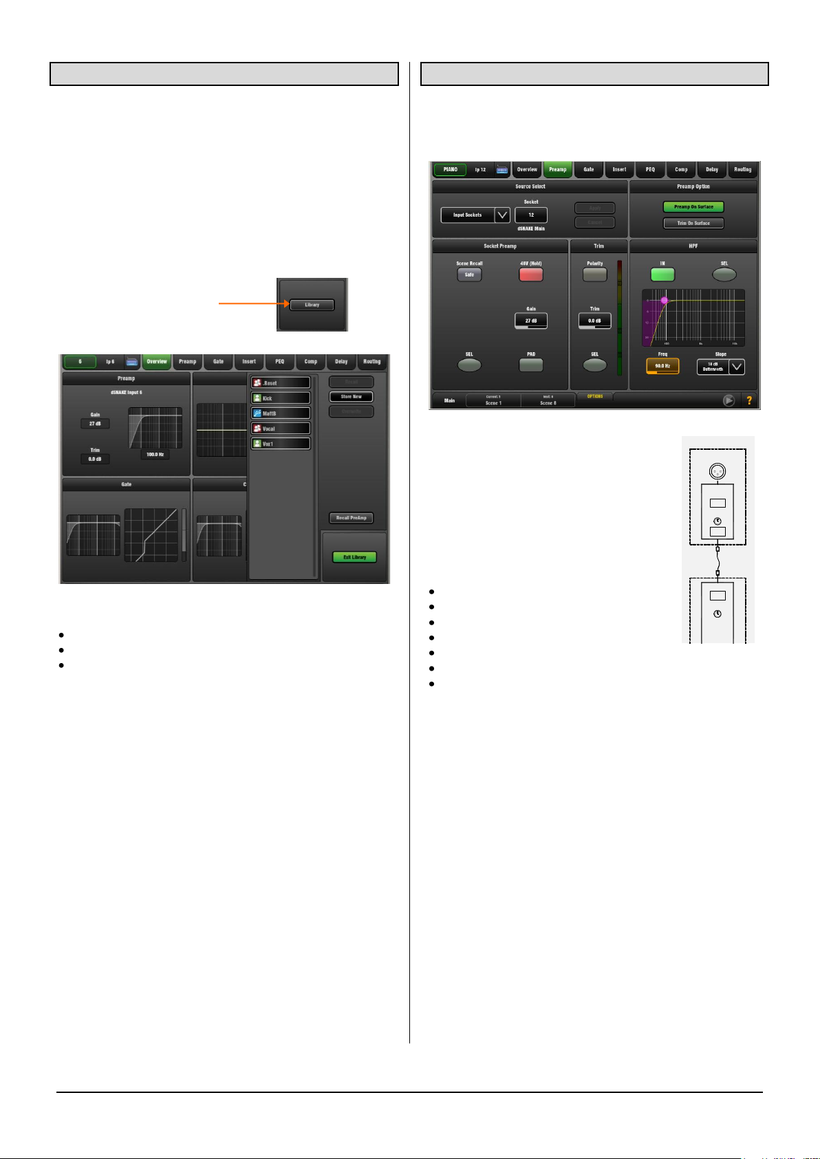
3.5 Channel Libraries
Libraries let you store and recall presets for individual
processing blocks such as EQ and Compressor, and also
for the whole Input or Mix channel.
Input and Mix channel processing Libraries do not store
routing, levels or assignments.
The Library window lists available presets. Input and mix
channel Libraries are accessed from their Overview page.
Touch the Library button to open the Library window. Touch
Exit Library to close the window.
The list shows 3 types of Library:
Factory (cannot be deleted)
User (stored in memory in the GLD)
USB (accessed directly from the USB key)
Touch to select a Library item and use the buttons to Recall
or Overwrite the item. Touch Store New to store a new User
Library item. Use the name keypad to apply a name of up to
8 characters.
User and USB Libraries cannot be deleted from this page.
Go to the Setup / Memory / Library Manager page to
delete and rename Libraries or transfer them between the
GLD and a USB key.
Input Library Preamp recall – Input Libraries store the
Preamp settings and all channel processing including HPF,
Gate, PEQ, Compressor and Delay. The Recall Preamp
button gives you the option to include or exclude Preamp
settings when recalling the Library.
The Recall Preamp button setting is remembered when
changing channels.
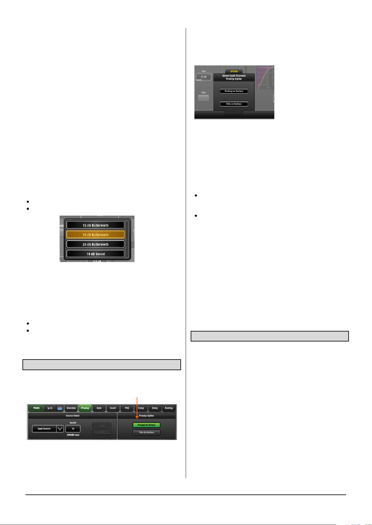
3.6 Preamp page
The Preamp page provides access to the Input Channel
source patching, socket Preamp settings, and channel Trim
and HPF.
Touch a control box to highlight a
parameter then turn the screen Rotary to
adjust its value.
Socket Source – Open the drop-down
menu to choose which source to patch to
the channel. Touch Apply to accept or
Cancel to leave unchanged.
Sources that can be patched:
An AudioRack input (via dSNAKE)
A GLD rear panel input
An I/O Port input
The USB stereo playback
One of the built-in effects (Rack FX)
The Signal Generator (as a test source)
The output of any Mix
To provide a simple starting point the Template Show
default is one-to-one mapping between input sockets and
channels. For example, Socket 1 to Channel 1, Socket 2 to
Channel 2 and so on.
Socket Preamp – If the patched source is a Mic/Line XLR
input then its Preamp controls are shown. These provide
remote control of the input preamp circuit located at the
socket.
Gain – Touch to highlight the Gain value box. Turn the
screen Rotary to adjust.
Phantom power - Touch and hold the 48V button for 1
second. This is to prevent accidental operation.
Pad switches in a 20dB input attenuator. The combined
Gain+Pad value is shown in the Gain box.
Preamp Safe – Touch this button to make Preamp Gain
Pad and 48V settings safe from Scene recall. This can be
useful when splitting the same mic preamp to two or more
channels.
GLD Touch Screen Reference V1.4 – Issue 1 8 ALLEN&HEATH
Page 9
Note Making a channel Safe using the surface Safe key
automatically makes the associated Preamp safe. Turning
off Safe using the surface key unsafes the Preamp.
Trim can provide +/-24dB ‘gain’ control when the source
does not have a preamp, for example input from GLD
surface RCA line inputs, the I/O Port or USB playback. Trim
is part of the channel, not the preamp.
When working with mic preamps it is typical to leave Trim
set to 0dB unless you are gain sharing and want to adjust
local level independent of preamp Gain.
Polarity toggles normal and reverse (+/- balanced input
pins swapped). Use to compensate for reverse wired
cables, or when double miking sources such as a snare
drum with ‘top’ and ‘bottom’ mics, or kick drum with ‘in’ and
‘out’ mics. Polarity is part of the channel, not the preamp.
HPF – The High Pass Filter cuts low frequencies, for
example to reduce pops or wind noise on microphones or
tune out unwanted low end on acoustic instruments. Its cutoff frequency is adjustable from 20Hz to 2kHz.
The HPF provides a choice of slope from a gentle 12dB to
steep 24dB/octave. Two filter types are available:
Butterworth – Maximally flat frequency response.
Bessel – Maximally linear phase response.
The filter can be switched in or out of circuit. A good
starting point for vocal mics is to switch the HPF in and set
to around 120Hz.
The HPF can also be viewed and adjusted in the PEQ page.
Screen Sel buttons – These do the same as their related
surface Processing Strip Sel keys:
Use with the Copy/Paste/Reset keys
Hold to listen to (PFL) the signal at that point if the
‘Disable PFL on Sel’ option is set to Off in the Setup /
Audio / PAFL screen.
3.7 Preamp Option - Gain/Trim on Surface
The Preamp Option lets you choose whether the
Processing Strip Gain rotary controls the Preamp Gain or
channel Trim.
Preamp on Surface – The surface Preamp rotary adjusts
Preamp Gain. This is the default for normal single console
operation.
Trim on Surface – The surface Preamp rotary adjusts
Channel Trim. Consider using this in situations where you
are sharing the same Preamp between channels or FOH
and Monitor consoles.
OPTIONS pull-up window
Provides a global setting for Preamp or Trim on Surface.
This affects all input channels.
Touch the pull-up tab and swipe your finger upwards to
open its window.
A note about Gain Sharing
Any Preamp can be patched to any Channel. The same
Preamp can be patched to more than one channel. For
example:
One set of channels within the GLD allocated to the
FOH mix and another split from the same mic inputs for
important channels feeding the monitor mixes.
Mic preamps split between dedicated FOH and Monitor
consoles using a digital snake connected to the GLD I/O
Port.
In the above cases the Preamp is shared by two channels.
The ‘Master’ console has control of the preamps and mic
Gain. The ‘Slave’ console gets its inputs from the digital
split. Its surface Preamp rotary becomes Channel Trim as it
does not have mic preamps. However, it will be affected by
preamp Gain changes made at the Master.
It is of course best that the FOH and Monitor engineer each
have independent control of channel gain.
A solution is to set the Preamp Gain during sound check
and for both engineers to use the Trim rather than Gain
controls during the show. This means setting the ‘Trim on
Surface’ option on the ‘Master’ console.
3.8 Mix Ext In source
You can assign a source as an external input to the mix, for
example for bus summing, combining console outputs, or
an external communications or test source.
The Ext Input sums with the GLD mix pre-insert and is
affected by the master processing and fader.
Source Select – Open the drop-down menu to choose
which source to patch to the mix output. Touch Apply to
accept or Cancel to leave unchanged.
Trim - Provides +/-24dB level control. This only affects the
Ext Input. Start with Trim set to 0dB.
Polarity - Toggles normal and reverse (+/- balanced input
pins swapped). This only affects the Ext Input to the mix,
not the mix.
Socket Preamp – If the patched source is a Mic/Line XLR
input then its Preamp controls are shown. These provide
remote control of the input preamp circuit located at the
socket.
GLD Touch Screen Reference V1.4 – Issue 1 9 ALLEN&HEATH
Page 10
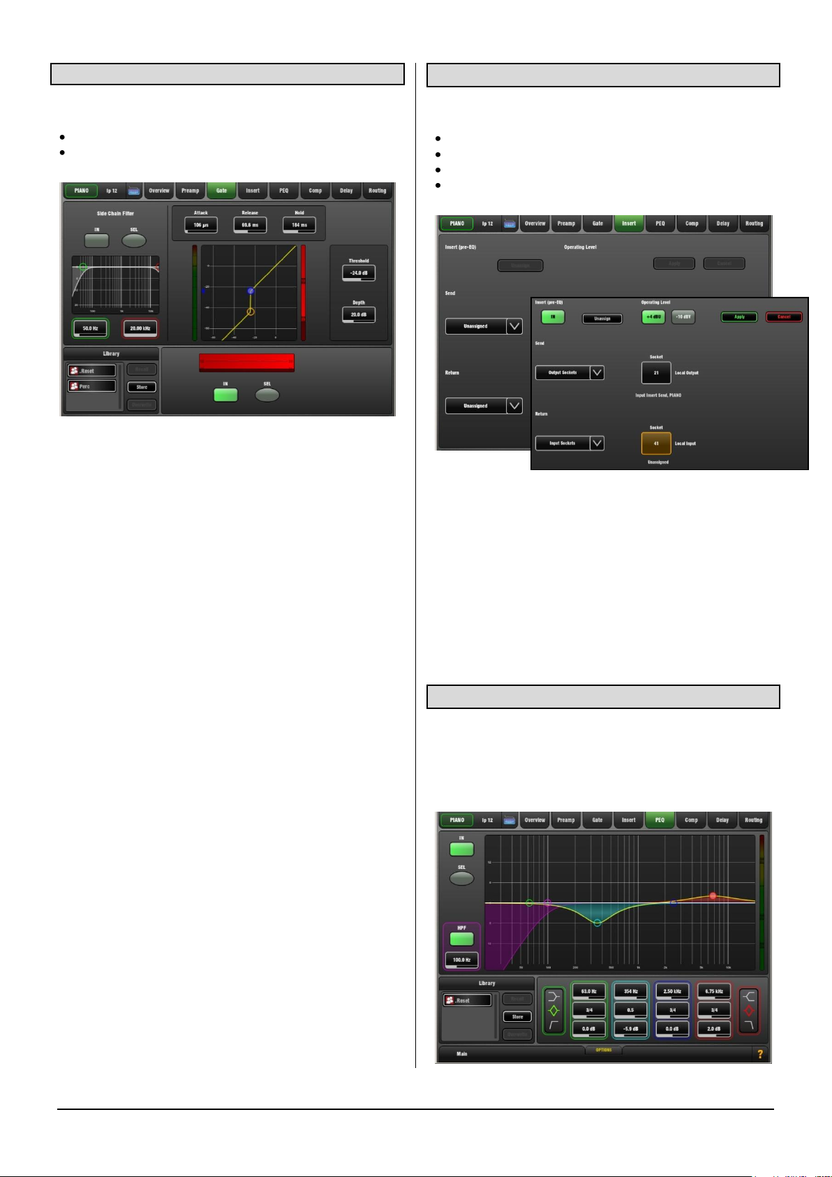
3.9 Noise Gate page
3.10 Insert page
The Noise Gate automatically attenuates the signal when it
drops below its threshold level. For example to:
Reduce excessive ring on a kick or tom drum
Reduce hiss on a noisy keyboard when not played.
Touch and drag the curve or touch a parameter box. It
highlights orange to show its value can be adjusted using
the screen Rotary.
Depth - Sets how much the signal is attenuated when the
gate closes. A good starting point is around 30dB. Reduce
for less attenuation. If Depth is set to 0dB the gate will not
attenuate the signal.
Threshold - Sets the level at which the gate opens to let the
signal be heard. The meter on the left lines up with the
graph and shows the signal at the input to the gate. The
gain reduction meter on the right shows when the gate is
closed. The histogram below shows gate activity over time.
Attack, Hold, Release - These controls set how fast the
gate opens when the signal rises above the threshold, how
long it is held open after the signal falls below the threshold
and how long it takes to attenuate after it closes.
Side Chain Filter - Sets the frequency range of the signal
that triggers the gate. Use this to prevent false triggering of
the gate by filtering out low or high frequencies outside the
fundamental range of the instrument being gated. For
example, the low frequencies of a kick drum causing the
gate on a rack tom to open.
In - Switch the gate in or out of circuit. The side chain can
also be switched in or out of the gate. The curve turns
yellow and the gain reduction meter displays red when the
gate is switched in.
Library - You can store and name the current gate settings
as a preset in the Library. Existing presets can be
overwritten with the current settings. User Libraries can be
exported and imported via USB key. To do this go to the
Setup / Memory / Library Manager screen.
Sel buttons – Touch while holding the Copy, Paste or
Reset key to copy the gate settings to other channels or to
reset them to default.
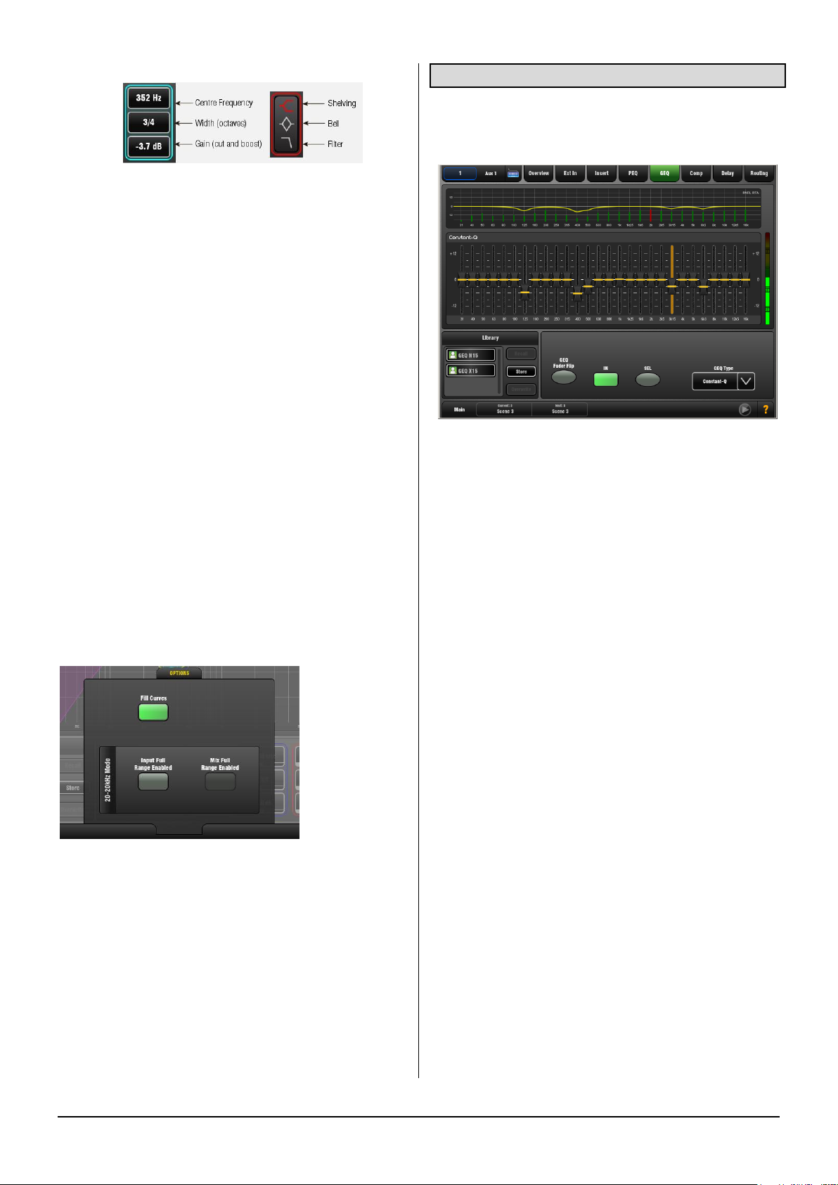
You can insert external equipment or one of the 8 internal
FX units into a channel or mix signal path:
An external signal processor using physical sockets
One of the 8 internal Rack FX
Computer plug-ins via the I/O Port
Networked audio via the I/O Port
Use the drop-down menus to assign the Insert Send and
Return to physical sockets, the I/O Port or an FX unit.
Touch Apply.
In button – Becomes available once the insert is assigned.
Switch the inserted device in or out of circuit.
+4dBu/-10dBV – Choose the operating level of the insert
point. +4dBu (default) is the typical setting for professional
audio equipment. -10dBV (-8dBu) is a standard for lower
level consumer equipment.
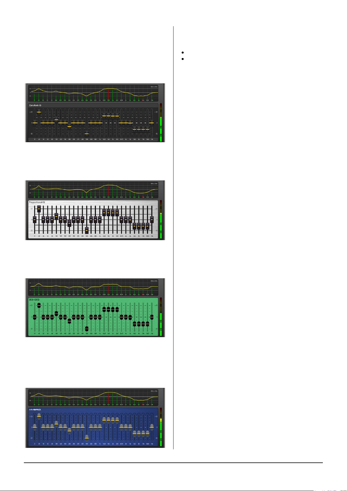
3.11 PEQ page
The Parametric Equaliser (PEQ) provides 4 fully adjustable
bands of equalisation allowing very precise tone control. It
can be adjusted using dedicated rotary controls on the
surface or using the touch screen. For screen control, touch
and drag the curve or touch a parameter box and use the
Rotary.
GLD Touch Screen Reference V1.4 – Issue 1 10 ALLEN&HEATH
Page 11
In - Switch the PEQ in or out of circuit. The curve turns
yellow when switched in and grey when switched out.
Type - The LF and HF EQ bands may be set as shelving,
bell shaped or low/high cut filter response. When set as a
filter the response is 12dB/octave.
Frequency - Sweeps the shelving, centre or cut-off
frequency depending on the type of the EQ band.
Width - Adjusts the width of the bell shaped EQ band.
Push and turn the Frequency rotary or use the screen. The
value is shown in octaves. Higher values up to 1.4 affect a
wider range of frequencies. Lower values down to 1/9th
affect a narrower range. A value of 1/3 has a similar affect to
the Graphic EQ.
Gain - Allows up to +/-15dB boost or cut for each EQ
band. 0dB represents a flat response. It is typical to cut
rather than boost when live mixing.
HPF - The High Pass Filter attenuates low frequencies
below its cut-off frequency with a slope of 12dB/octave.
Switch in or out using the In button. The HPF can also be
adjusted using the Preamp page.
Library - You can store and name the current PEQ
settings as a preset in the Library.
OPTIONS pull-up window
The frequency range for the 4 bands may be set globally for
all inputs or mixes to be limited or full 20Hz to 20kHz.
A Fill Curves option to show the overall or individual effect
of the EQ bands is available.
Sel button - Touch while holding the Copy, Paste or Reset
key to copy the PEQ settings to other channels or to reset it
flat.
3.12 GEQ page
A 28-band 1/3 octave Graphic Equaliser is provided on
each of the 20 mix outputs. It can be adjusted using the
touch screen or the surface faders.
Frequency response curve – The top part of the screen
shows the combined response of the slider settings. This
can show the response differences between the four GEQ
types available.
RTA display – The Real Time Analyser display is
superimposed on top of the frequency response curve. The
RTA displays metering of the currently selected PAFL signal
split into its 1/3rd octave frequency bands. The meter bars
are shown in green. A red bar and a dot at the top indicate
the dominant frequency band if the Show Peak Band option
has been set in the Meters / RTA screen Options pull-up
window.
Note The RTA follows the current PAFL selection. Make
sure you have selected the PAFL key for the channel or mix
you wish to analyse, for example the related Aux mix when
you are using the GEQ and RTA to ring out a stage monitor.
Using the Screen to control the GEQ
Touch a frequency slider to highlight it. Drag the slider with
your finger or use the screen Rotary to adjust cut or boost
for the highlighted frequency band.
In - Switch the GEQ in or out of circuit. The settings turn
yellow when switched in and grey when switched out.
Sel button – Touch while holding the Copy, Paste or Reset
key to copy the GEQ settings to other mixes or to reset all
bands flat.
Using the Faders to control the GEQ
While the mix Sel key is active, press the GEQ Fader Flip
key to the right of the faders. The fader strips and their
displays show the settings of the GEQ frequency bands.
The right hand fader becomes the master for the selected
mix. The meters above the faders display the RTA for the
currently selected PAFL. Press GEQ Fader Flip to toggle
between frequency ranges and back to normal mixing.
GLD Touch Screen Reference V1.4 – Issue 1 11 ALLEN&HEATH
Page 12
GEQ Type – Use the drop-down menu to select one of four
GEQ types available. These offer different types of
cut/boost response:
Constant-Q - Symmetrical cut/boost where the width (Q) of
the filter is a constant 1/3rd octave for any amount of cut or
boost.
Proportional-Q - Provides smooth wide Q for low
cut/boost, which progressively tightens beyond 1/3rd
octave for max boost/cut.
Digi-Q - Gain and width are optimised to minimise band
interaction and to provide a frequency response as close to
the slider positions as possible.
Using the faders to control the GEQ
You can quickly access the GEQ on the faders for the mix
with its Sel key active by:
Touching the screen GEQ Fader Flip button, or
Pressing the GEQ Fader Flip key to the right of the
faders while in any of the mix Processing pages.
This puts the lower frequency half of the GEQ on to the
faders. Press again to present the higher frequency half,
and press again to return to normal fader mode.
The frequency values are shown in the strip LCD display
which turns red while in Fader Flip mode.
In Fader Flip mode the extreme right hand strip becomes
the Master for the mix currently selected. The fader is either
the mix master or a channel send to that mix if a channel
Mix key is active. This lets you ring out a monitor mix by
adjusting the GEQ while raising the channel send rather
than master using this fader.
Press the fader strip Sel keys to reset individual frequency
bands flat. The green Sel indicator lights when the band is
flat.
Selecting the mix PAFL key and using the RTA Show Peak
Band option will let you see the RTA on the strip meters
and help you identify frequencies that start to ring.
Library - You can store and name the current GEQ
settings as a preset in the Library. Existing presets can be
overwritten with the current settings. User Libraries can be
exported and imported via USB key. To do this go to the
Setup / Memory / Library Manager screen.
Note The GEQ Type is stored as part of the GEQ Library.
Hybrid - Allen & Heath have developed the best of both
worlds. The boost is proportional-Q for smooth and warm
small boost settings. The cut is Constant-Q providing
clinical 1/3rd Octave attenuation with minimal band
interaction.
GLD Touch Screen Reference V1.4 – Issue 1 12 ALLEN&HEATH
Page 13
3.13 Compressor page
The Compressor is used to automatically reduce the
dynamic range of the signal by squashing loud sounds and
bringing up quieter sounds. For example, to smooth the
level of a b ass guitar or the dynamics of a vocal.
Touch and drag the curve or touch a parameter box.
Ratio - Sets the amount of compression when the signal
exceeds the threshold. A ratio of 1:1 means no
compression. A good starting point for vocals is around 3:1.
This means a 3dB rise in level at the input of the
compressor would result in a 1dB rise at its output. To use
the compressor as a limiter set the ratio to 'Infinity'.
Threshold - Sets the level at which the compression
starts. The meter on the left lines up with the graph and
shows the signal at the input to the compressor. Start with a
high setting and then dial it back until compression starts.
The gain reduction meter on the right shows how much the
signal is being compressed. The histogram below shows
compressor activity over time.
Gain - This is 'make-up' gain which boosts the output to
compensate for the drop in overall volume when the signal
is being compressed. Adjust so that you hear a similar
volume when switching the compressor in or out with
normal signal present. Set Gain to a higher value for higher
settings of Ratio and lower settings of Threshold. It is this
gain that makes quiet signals sound louder.
Note If you notice the channel strip meter Pk light flashing
while the meter reads low then check that you are not
overdriving the Preamp while the signal is being heavily
compressed. In this case back off the Preamp Gain and
turn up the compressor Gain.
Soft Knee - Determines how quickly the compression cuts
in. The Soft Knee adds compression gradually with more
gentle ratio as it approaches the threshold level. Use this for
more subtle compression of signals that hover around the
threshold level.
Attack and Release - These controls set how fast the
compressor pulls back the signal when it exceeds the
threshold and how long it takes to let go when the signal
drops below the threshold. Set this according to the type of
signal to avoid hearing a 'pumping' effect.
Side Chain Filter - Restricts the frequency range of the
signal that triggers the compression. Use this to filter out
low or high frequencies outside the range of the wanted
signal thus preventing false triggering. Extreme settings can
be used for special effect or frequency sensitive
compression, for example 'de-essing' to compress just a
range of high frequencies to reduce sibilance of a vocal.
The default is the filter switched out.
Compressor Type - Select one of the Manual or Auto
compressor emulations. Auto modes automatically adjust
the attack and release according to the dynamics of the
signal. In some cases this can be better for avoiding
'pumping' effects. Types available:
Manual Peak
Manual RMS
Auto Slow Opto
Auto Punchbag
Parallel Path - Lets you mix the dry path ‘uncompressed’
signal with the compressed output. This 1970’s studio
technique also known as 'New York compression' is useful
in live audio. By mixing the raw signal with heavily
compressed material (with make-up gain) low level detail is
amplified while the high level transients are preserved from
the raw signal.
With Parallel Path turned off only the compressed signal is
routed to the output. This is the default setting. With Parallel
Path turned on, the mix between ‘dry’ uncompressed and
‘wet’ compressed signal can be balanced using the
independent controls.
Library - You can store and name the current GEQ
settings as a preset in the Library.
Sel buttons - Touch while holding the Copy, Paste or Reset
key to copy Compressor settings to other channels or to
reset it to factory default.
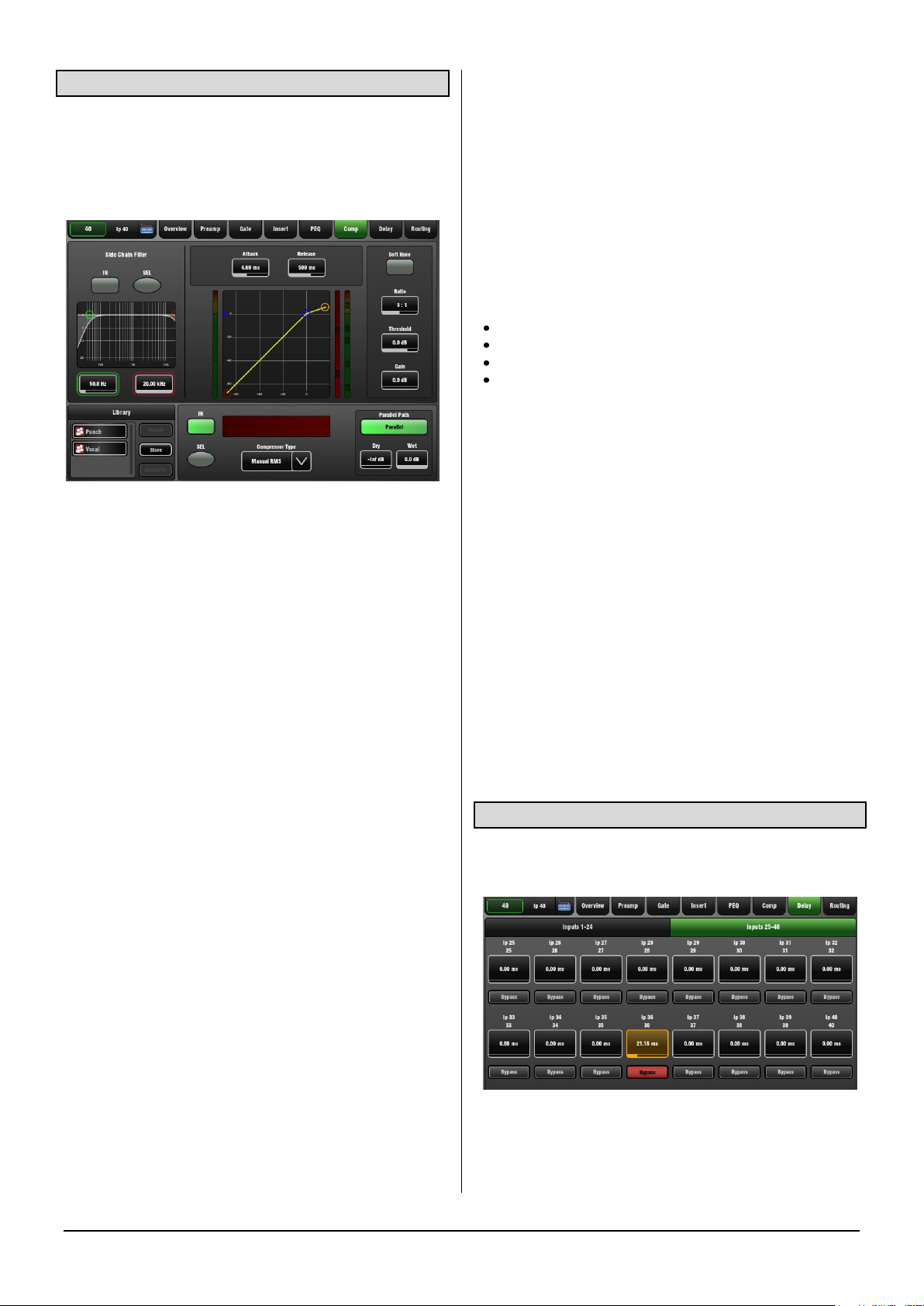
3.14 Delay page
The delay settings for all the channels or mixes are shown
on this screen page. Compare settings between channels.
The currently selected channel is highlighted. Use the
screen Rotary to change its value. Touch another
parameter box to adjust the delay for a different channel.
GLD Touch Screen Reference V1.4 – Issue 1 13 ALLEN&HEATH
Page 14
Delay Bypass - Touch the button to toggle the delay in or
out. Use this to compare the direct and delayed signal, for
example when you are time aligning delay fill speakers.
Input Delay
Input delay can be used to time align instruments to each
other or create extra ‘depth’ on stage.
Milliseconds 0 to 85 ms
Metres 0 to 29 m
Feet 0 to 96 ft
Samples 0 to 4094 s
Mix Delay
Mix delay is typically used to time align delay fill speakers to
the main PA, or to align the main PA to the back line such
as drum kit in a smaller venue where the acoustic sound
coming from the stage is significant. Range:
Milliseconds 0 to 170 ms
Metres 0 to 58 m
Feet 0 to 190 ft
Samples 0 to 8100 s
SETUP pull-up window
The default delay unit is time in 'ms' (milliseconds) but can
be changed to distance in 'metres', 'feet', or to 'samples.
This can be changed globally for the Input channels and for
the Mix channels. GLD compensates for the effect of
temperature on delay. Enter the ambient temperature if
distance is chosen.
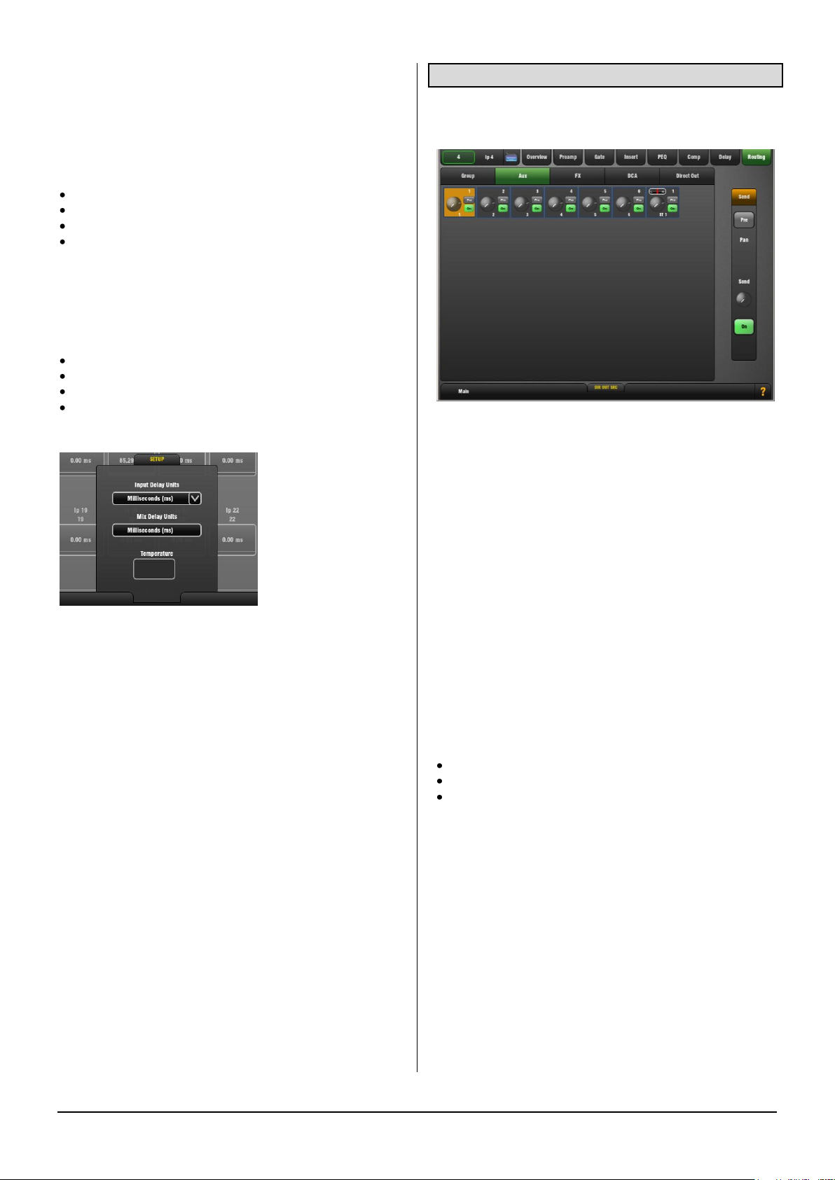
3.15 Routing Page – Input Channel view
The Input Routing page lets you view and adjust the
channel sends, routing, assignments and Direct Out.
There are two ways to work with channel Routing:
Using the touch screen – Press a channel Sel key. Touch
the screen Routing tab or press the Processing Strip
Routing key to open the Routing page for the currently
selected Input Channel.
Touch the tabs within the page to access the assignments
and send levels from the selected Input Channel to all
Groups, Auxes and FX, its DCA assignments, and adjust its
Direct Output level.
Touch a box to toggle single parameters such as DCA and
Group assignments. Touch a box to open the send panel
on the right of the screen to adjust multiple parameters
such as Aux send levels, assignments and Pre/Post
settings. The screen Rotary becomes the Aux send level
control as soon as the box is touched.
Using the GLD fader strips - Press an Input strip Mix key.
Current settings are shown in the master strip LCD displays
for:
Sends from the channel to all Auxes
Sends from the channel to all FX
Channel assignments to the audio Groups
While holding down the Assign key press master Mix keys
to toggle assignments on or off. While holding down the
Pre/Post key press Sel keys to toggle Aux sends pre or post
fader. Aux send levels can be adjusted using their master
faders while in Mix mode. Remember to press the strip Mix
key again to return to the main mix.
Aux sends – The send to each Aux can be set Pre or Post
fader from the channel. The point within the channel signal
path that feeds the send is set globally for each Aux using
its master Routing page.
For stereo Auxes a Pan control appears. This adjusts the
stereo image of the channel to the Aux and is not the same
as or affected by the main channel Pan control.
Direct Output – Open the Direct Out tab to access its level.
Normal setting is 0dB.
GLD Touch Screen Reference V1.4 – Issue 1 14 ALLEN&HEATH
Page 15
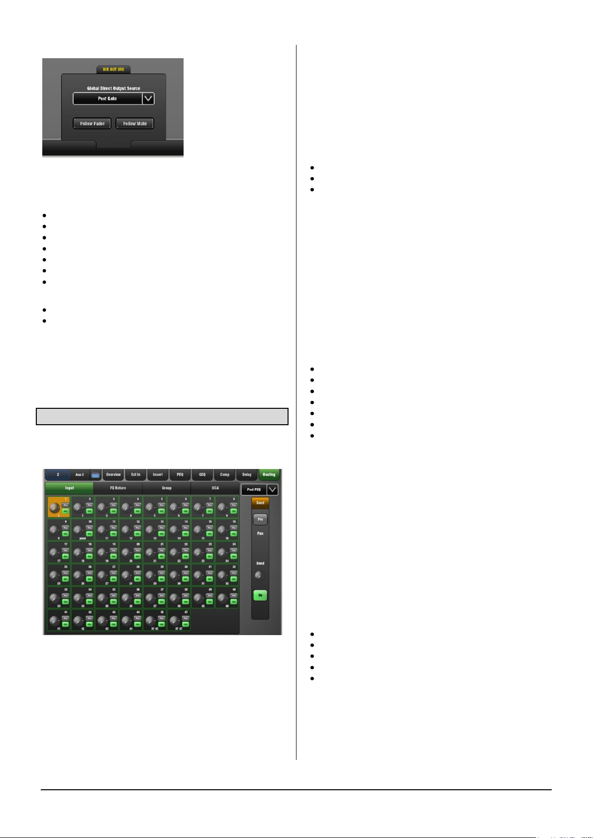
DIR OUT SRC pull-up window
The global source for the input channel Direct Outputs can
be set here using the drop-down menu. This setting affects
all channel Direct Outputs:
Post-Preamp
Post- HPF
Post-Gate
Post Insert Return
Post-PEQ
Post-Comp
Post-Delay
Touch the buttons to set:
Follow Fader (pre/post fader)
Follow Mute (pre/post mute)
Strip Rotary control Custom 1 and 2 views - These can
be configured as dedicated Aux or FX sends or Direct Out
level using the Setup / Control / Surface Prefs screen.
3.16 Routing page – Mix Master view
The Mix Routing page lets you view and adjust all sends
and routing from the channels.
There are two ways to work with master Routing:
Using the touch screen – Press a mix master Sel key.
Touch the screen Routing tab or press the Processing Strip
Routing key to open the Routing page for the currently
selected Mix master.
Touch the tabs within the page to access the assignments
and send levels from all Inputs, FX Returns and Groups to
the mix and its DCA assignments.
Touch a box to toggle single parameters such as DCA and
Group assignments. Touch a box to open the send panel
on the right of the screen to adjust multiple parameters
such as Aux send levels, assignments and Pre/Post fader
settings. The screen Rotary becomes the Aux send level
control.
Using the GLD fader strips - Press a master strip Mix key.
Current settings are shown in the channel strip LCD
displays. For example, with an Aux master selected:
Sends from all channels to the mix
Sends from all FX returns to the mix
Sends from all audio Groups to the mix
While holding down the Assign key press channel Mix keys
to toggle assignments on or off. While holding down the
Pre/Post key press Sel keys to toggle Aux sends pre or post
fader. Aux send levels can be adjusted using the channel
faders while in Mix mode. Remember to press the strip Mix
key again to return to the main mix.
To set all channels On or Pre/Post fader hold the Assign
or Pre/Post key and press the mix Master Mix or Sel key.
Aux send channel source – Use the drop-down menu at
the top right of the screen to set the point within the channel
signal path that feeds the Aux sends. This is set globally for
each mix:
Post-Preamp
Post- HPF
Post-Gate
Post Insert Return
Post-PEQ
Post-Comp
Post-Delay
Setting an Aux as a monitor send – It is typical to set the
source Post- Gate or Post-PEQ (so that the Compressor
does not affect the monitors, but choose whether channel
EQ does). Also set the sends Pre-Fade.
Setting an Aux as an effect send – Set the source Post-
Delay and all sends Post-fade so that the effect follows the
channel processing and fader levels.
Strip Rotary control Custom 1 and 2 views - These can
be configured as dedicated Aux or FX sends or Direct Out
level using the Setup / Control / Surface Prefs screen.
Groups / Aux / FX / Main Mix / Matrix
Routing:
Inputs + FX returns > Groups
Inputs + FX returns > FX sends
Inputs + FX returns + Groups > Aux sends
Inputs + FX returns + Groups > Main mix
Groups + Auxes + Main mix > Matrix
GLD Touch Screen Reference V1.4 – Issue 1 15 ALLEN&HEATH
Page 16
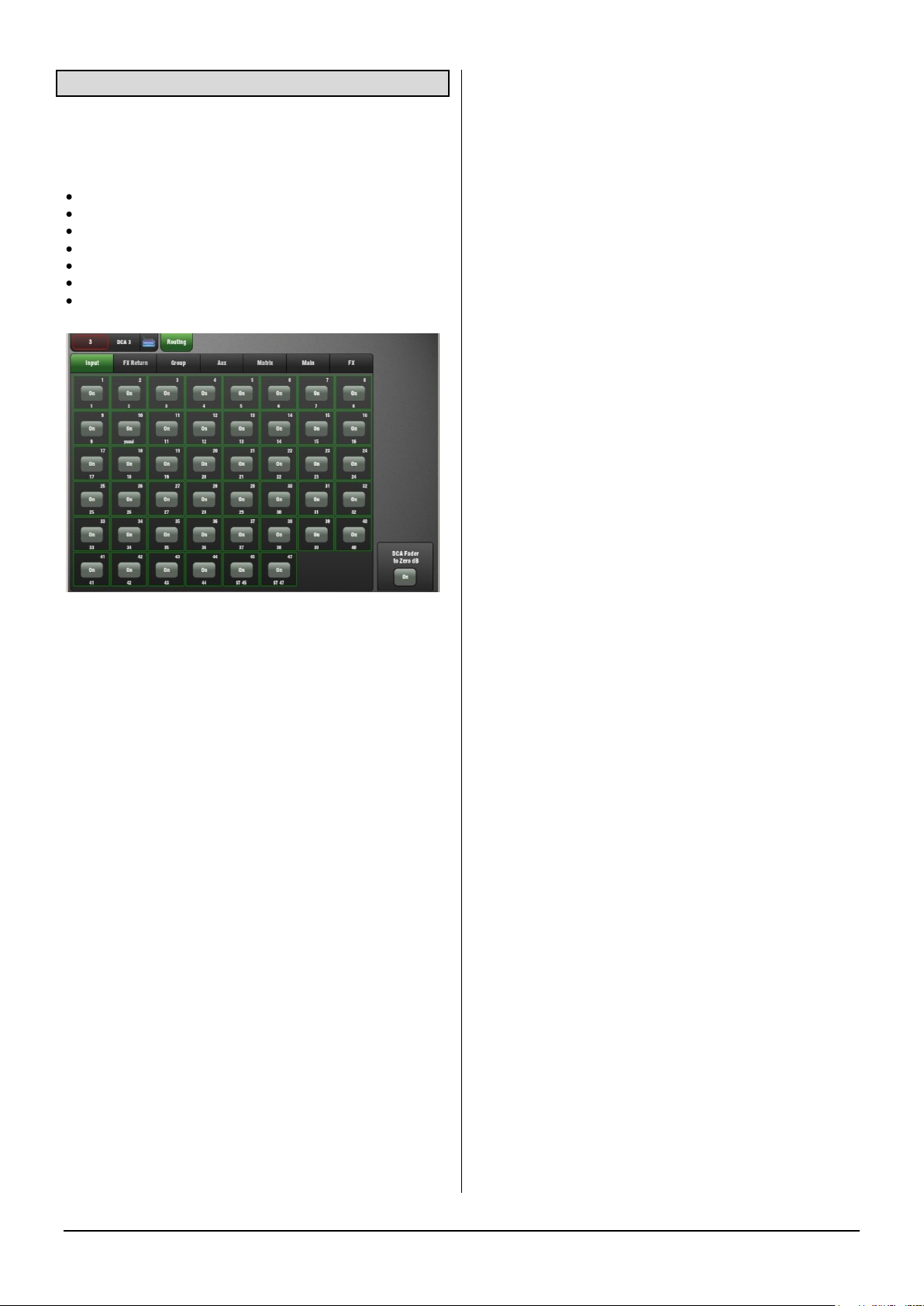
3.17 Routing page – DCA Master
GLD provides 16 DCA Groups. These can be used as DCA
Groups (level control) or Mute Groups (mute masters).
The following can be assigned to DCA Groups:
Input channels
FX returns
FX sends
Group masters
Aux masters
Matrix masters
Main LR master
The DCA master affects the level and mute of an assigned
channel back at its fader point. It is another level stage in
line with the channel fader. It does not physically move the
channel fader. A separate indicator next to the channel
Mute key shows if it is muted by one or more DCA groups.
Channels can be assigned to multiple DCA Groups. For
example, drum channels could be assigned to a DRUM
DCA and also to a BAND DCA.
To use DCA Groups
Assign channels to the DCA Group.
Set the DCA master fader to its ‘0’ position. This is its
normal operating position. This position results in the same
level as if the channel was not assigned to the DCA.
You can adjust the level of the assigned channels up or
down using the master fader, but always start with it set to
‘0’.
Note If you get no signal when you raise a channel fader
check that it is not turned off by a DCA master.
There are two ways to assign DCA Groups:
Using the touch screen – Press a DCA master Sel key.
The screen opens in the DCA Routing page.
Touch the tabs within the page to access the assignments
of the channels, FX and mixes to the DCA Group. Touch the
buttons to assign to the DCA Group.
Using the GLD fader strips - Press a DCA master strip Mix
key. Current assignments are shown in the source strip
LCD displays. The ‘ON’ icon displays for sources currently
assigned.
While holding down the Assign key press source strip Mix
keys to toggle assignments on or off. Remember to press
the master strip Mix key again to return to the main mix.
DCA Fader to 0dB option – Select this if you want to use
the DCA as a Mute Group. This disables the DCA master
fader and sets it to its ‘0’ position. If you try to move the
fader it will return to this position. Use the DCA Mute key as
the Mute Group master.
DCA Groups explained
A DCA group provides a master fader and mute to remotely
control the level of channels assigned to it.
Audio does not route through DCA groups as it does
through conventional mix Groups. GLD provides both types
of grouping. Use DCA Groups for level control and mute
grouping. Use Mix Groups for grouped signal processing
such as compression and for routing of grouped signals to
Aux or Matrix mixes.
GLD Touch Screen Reference V1.4 – Issue 1 16 ALLEN&HEATH
Page 17
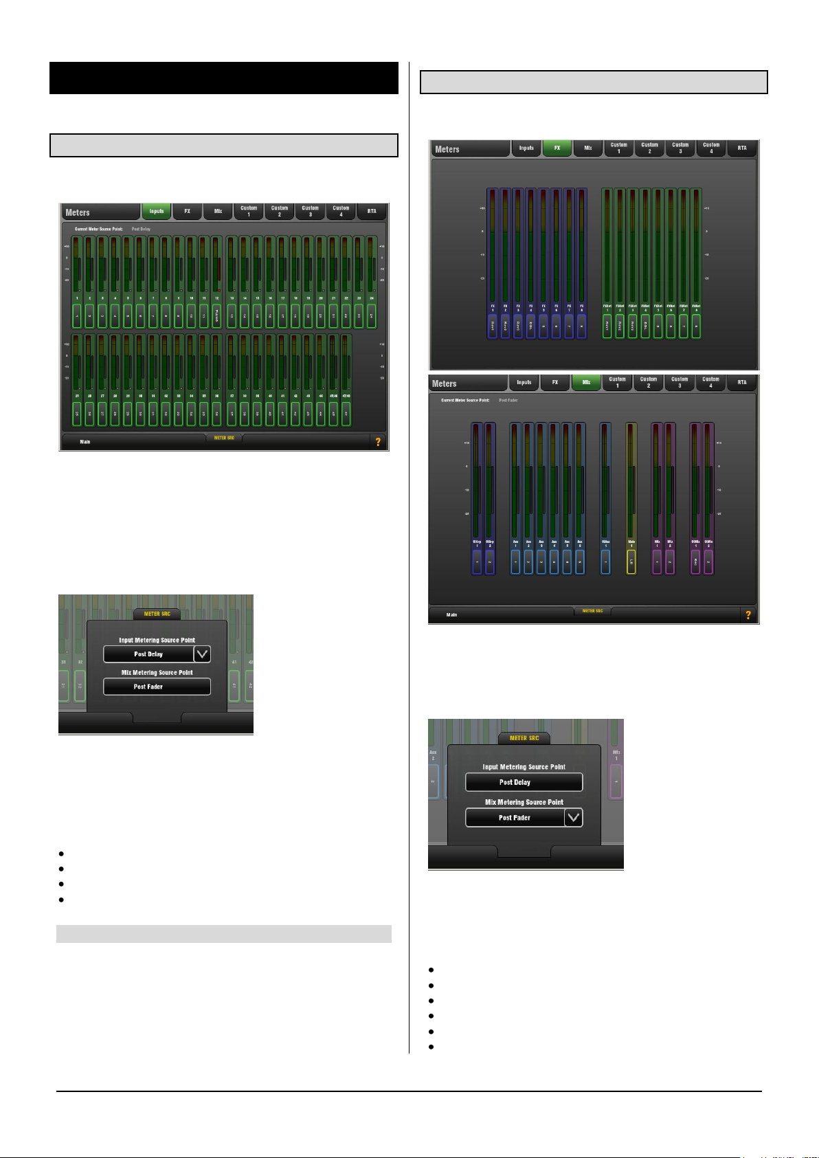
4. Meters Screen
4.1 Input Meters page
Meters for all 48 Input Channels are displayed on this page.
Channel Name and Colour is shown below each meter.
The Compressor Gain Reduction meter is shown to the
right with the Gate Active indicator below it. These show
activity in red when switched In, and in grey when switched
out of circuit.
4.2 FX and Mix Meters pages
These pages show meters for all FX and Mixes available.
METER SRC pull-up window
The Input meter source point can be globally set for all
meters in the Inputs page. This does not affect the fader
strip or other screen metering.
The following options are available (all Pre-Fader):
Post-Trim
Post-Gate/PEQ
Post-Compressor
Post-Delay (Default)
The Compressor Gain Reduction meter is shown to the
right with the Gate Active indicator below it.
METER SRC pull-up window
The meter source point can be globally set for all meters in
the Mix page. This does not affect the fader strip or other
screen metering.
The following options are available:
Pre-Insert
Post-Insert Return
Post-PEQ
Post-GEQ
Post-Compressor
Post-Fader (Default)
GLD Touch Screen Reference V1.4 – Issue 1 17 ALLEN&HEATH
Page 18

4.3 Custom 1-4 Meters pages
You can assign 4 Custom meter views.
These can be viewed in the Home or Meters screens.
Custom Meters let you organise the meters of channels and
mixes you are using into a single screen view, leaving off
those you are not using.
Assign up to 32 meters per page in two rows with up to 16
meters per row.
4.4 RTA
The RTA provides a 1/3 octave 'Real Time Analyser'
frequency display for the signal currently PAFL signal.
The RTA can be viewed in the Home or Meters screens. It
also displays on the strip meters when GEQ Fader Flip is
active. It separates the signal being listened to on the PAFL
monitor into 31 frequency bands and shows the relative
strength of each as a real time display.
When enabled, the RTA Peak Band option displays the
dominant frequency as a red bar in the RTA screen or by
lighting the red Pk indicator on the related strip meter while
in GEQ Fader Flip mode. Only one band will be lit red.
Note The RTA follows the PAFL signal. Check that you
have selected PAFL for the signal you wish to analyse.
OPTIONS pull-up window
Choose to hide or show the RTA Peak Band display on the
RTA screen or GEQ Fader Flip views.
SETUP pull-up window
Open the pull-up to assign meters to a Custom Meter page.
Use the tabs at the side to access available Inputs, FX
sends and returns, Mixes and PAFL monitor.
Touch items in the top window to drop them into available
empty slots below, or drag them into the position you
require. You can:
Add meters by touching or dragging
Insert meters by dragging between slots
Remove meters by dragging out of the window
Add spaces between meters
Add or remove the second row
Touch Apply to accept or Cancel to discard the changes.
Exit setup by closing the pull-up screen when you are
finished.
GLD Touch Screen Reference V1.4 – Issue 1 18 ALLEN&HEATH
Application
Use the RTA to help identify problem frequencies such as
instrument or room resonance or feedback.
With the Peak Band option enabled the RTA is a good tool
to help identify feedback frequencies while ringing out
stage monitors. Carefully raise the level of a vocal mic until
the monitor just begins to ‘ring’. That frequency will be
shown as the peak band and can be cut on the related Aux
mix Graphic EQ.
Page 19

5. FX Screen
5.1 Front Panel view
Access the FX using the FX screen or by pressing Sel keys
for individual FX Send or Return fader strips.
The FX Screen presents the 8 virtual rack slots shown
across the top of the screen either empty or with FX devices
already loaded. The FX name, current library loaded and
metering is shown next to each icon.
Select one and open up either the Front or Back Panel
view.
To change or load an FX:
Touch the panel name box and scroll using the Rotary
Touch the Library button to open the Library page
The Front Panel view presents the FX parameters. Touch a
parameter box or control and use the screen Rotary to
change the setting.
The Lower panel shows the current routing, levels and
metering for the FX device.
Mix>Return type FX - The Send and Return paths are
shown. These are the same controls as found on the
associated Send and Return fader strips.
Insert type FX – Shows which channel the FX is inserted
into, the Insert In/Out switch and a Dry/Wet control to adjust
the balance of direct and effect signal.
Note If you are not hearing the effect when you raise a
channel in the FX mix then check that the related Send
master and Return faders are turned up and that they are
not muted or affected by a DCA Group.
PEQ – Each FX Return has a 4-band Parametric Equaliser.
Touch the PEQ button to open the FX PEQ popup. Touch
again to close it. Touch the Param button to choose to
adjust the EQ by dragging a curve or changing values
using the Rotary.
The PEQ can also be accessed by pressing Sel on the FX
return (IP FX) fader strip.
5.2 Back Panel view
The Back Panel view lets you view and change how the FX
are patched into the GLD signal path.
You can patch each FX slot as:
Unassigned
Insert
Mix>Return
Touch Apply or Cancel to accept or discard your changes.
Unassigned – The FX device is not patched.
Insert – Insert an FX device into an input or mix channel.
This breaks the signal path at its insert point to route it
through the FX and back into the channel. An Insert In/Out
switch and Wet/Dry balance control is provided.
Mix>Return – Patch the FX device as a ‘System Effect’
where channels can be mixed to the effect using a Send
bus and returned through a dedicated stereo Return
(FXRet) channel to add the effect (wet) signal to the direct
(dry) signal routed to the main mix.
Mix>Return is used for effects such as reverb and delay.
GLD has 8 ‘short’ stereo Return channels dedicated to the
FX. Together with the 48 input channels this provides up to
56 sources to the mix.
GLD Touch Screen Reference V1.4 – Issue 1 19 ALLEN&HEATH
Page 20

Chaining FX - FX devices can be routed to each other. For
example you could patch the output of a Delay unit into a
Reverb, and then return the reverb to the main mix.
View Outputs – Touch the View Outputs button to open a
window showing where the outputs of the FX device are
routed. Each slot can handle up to 8 outputs depending on
the device loaded. Most provide 2 outputs (stereo).
Unassign – Touch this button to reset the FX device
outputs to feed its related short FX Return channel.
5.3 FX Libraries
Touch the Library button to open the Library window. Touch
the Exit Library button to close the window.
The Libraries are grouped according to FX type. You can
choose to load one of many 'Factory' presets from the
menus, or to recall a previously stored 'User' preset from
the memory or directly from your USB key.
Factory, User/USB – Touch to show the available Factory
presets or to show the User presets currently stored in GLD
memory and those found on a USB key plugged in.
Recall – Scroll through the list and touch to select a preset.
Touch Recall to load the highlighted preset.
Store New – Touch to store the current FX settings as a
User preset. Name the preset using the touch keypad.
Overwrite - To update an existing User preset first select it
in the list then touch the Overwrite button. Factory presets
cannot be overwritten or deleted.
User Libraries can be deleted or transferred to or from your
USB key using the Setup / Memory / Library Manager
page.
Note You do not need to use up FX slots to attach Graphic
Equalisers to the mixes. Each of the 20 mix outputs has a
GEQ available within its processing screen.
5.4 FX Devices available
SMR Reverb
SMR Live is a Spatial Modelling Reverberator featuring 4
fully configurable complex spatial models Classic, Hall,
Room and EMT. Each of these models use different
reflection and decay algorithms to provide natural sound
spaces ideal for Live sound.
Classic Emulates high quality plates. Shape tailors the
reflection pattern. Min position for fast attack, mid position
for rounded early reflections, and max position for
separated early and late reflection patterns. Adjusting
shape/size/predelay with decay can result in some great
Hall reverbs. Small size settings not very useful in live
sound applications.
Hall Emulates a real Hall reflection model. No shape
control, reflections are controlled with Size, Source diffusion
and Ref detail with rich deep decay spectrum.
Room Accurately emulates a characteristic complex room
reflection pattern.
EMT Classic plate emulation. A great plate with good tonal
balance for live use. Decay setting around 2 seconds is
typical.
The SMR primary controls essential for live mixing are
always visible:
LF Cut - 0 to 400Hz, 24dB/octave high pass filter to cut low
frequencies of the input signal to the reverb.
HF Cut - 2kHz to 20kHz, 24dB/octave low pass filter to cut
high frequencies of the input signal to the reverb.
Predelay - The time it takes before the reverb reflections
and decay are heard.
Decay Time - Broad spectrum decay control. The time it
takes for the reflections to decay to 60dB below the level of
the direct sound is known as the RT60, an important
measurement of reverb in a room.
HF Decay - Frequency at which the high frequency decay
attenuation starts.
HF Slope - The attenuation slope of the high frequency
decay. HF Decay and Slope are both essential for high
frequency decay spectrum adjustment in a live space.
Setting HF Decay and Slope low creates a natural sounding
decay. Setting HF Decay and Slope high creates a dramatic
decay.
GLD Touch Screen Reference V1.4 – Issue 1 20 ALLEN&HEATH
Page 21

In addition there are 5 pages of scrollable ‘Expert’ pages for
the Reverb which allow precision control:
Page 1 - Reflections - Source Diffusion, Size, Shape, Ref
Detail.
Dedicated to reflection control. Keep source diffusion and
detail low to help intelligibility. Small sizes are not typical for
live applications. ‘Shape’ is only available in the Plate
model.
Page 2 - Echoes - Echo1, Echo1 level, Echo2, Echo2 level.
Dedicated page for user defined echo reflections. You can
insert main reflections to create Echo reverb sounds. Echo1
goes to left Echo 2 goes right. Echoes may be layered over
the reverb.
Page 3 - Decay Texture - Body Diffusion, Tail diffusion,
Mod depth, Mod speed.
Separate body and tail diffusion controls can help prevent
metallic decay through too much diffusion. Modulation
depth and speed increase reverb density and add
chorusing, effective on percussive program but not as
useful on piano and vocal.
Page 4 - Decay Spectrum - LF decay, LF XOver, Colour,
Colour Freq.
Separate LF decay control with crossover frequency and
decay time, useful for live work. Colour is a tuneable
element in the decay. High Freq colour settings can
enhance ambience, although it can sound metallic with
some programme.
Page 5 - Reflection/decay level - Reflection level, decay
level.
These controls are dedicated to balancing reflection and
decay to improve intelligibility.
Preset Name is displayed in the simulated LCD window.
Touch and scroll using the screen Rotary for live update.
This is a way of live auditioning all library presets for this
module (factory, user and USB). You can also select and
recall a particular preset using the Library window.
2-Tap Delay
Separate left and right tap delay outputs from a mono’d
input. Left and right delay can be dialled in using the screen
Rotary, tapped on screen or tapped using a SoftKey.
Individual tap indicators flash at the tap rate.
The left and right delay taps can be ganged to mono using
the Link button. There are adjustment controls below each
delay tap for fine tuning the values.
The regen path (feedback) has a low pass damping filter.
This filter has a frequency and a slope control for fine
adjustment of loop delay HF attenuation. There is also a
stereo output width control.
LF Cut - 20Hz to 8kHz HF Cut 400Hz to 20kHz These filters
control the input spectrum. The 24dB/octave slope gives
brick wall control on what signal spectrum gets delayed.
Delay range - 5ms to 1360ms Delay tap controls Left and
Right are tappable, shown with flashing leds.
Fine delay Left and Right adjustment in 1ms steps.
Link sets Left and Right tap delays equal with one control.
Scatter modifies the delay pattern between Ping-Pong and
scattered. Scatter off - creates classic Ping-Pong delays.
Scatter in - reconfigures the regen path giving one delay on
the shortest side and regen on the longest side replacing
Ping-Pong bounce with some interesting delay patterns.
For example, an echo on one side and a regen echo
pattern on the other.
Feedback controls the regeneration of the delay, creating
loop delays. Feedback filter controls HF attenuation in the
regeneration path/loop delay. The frequency and slope
controls give the engineer precise HF attenuation control in
the delay loop. Slope set mid for typical settings. Slope
minimum is a light HF attenuation setting, maximum
position is a large HF attenuation setting.
Width controls the stereo width of the output. Min position
= mono, max position = LR.
Preset Name is displayed. Touch and scroll using the
screen Rotary for live update. This is a way of live
auditioning all library presets for this module (factory, user
and USB). You can also select and recall a particular preset
using the Library window.
GLD Touch Screen Reference V1.4 – Issue 1 21 ALLEN&HEATH
Page 22

Gated Verb
ADT Doubler
An accurate emulation of the classic 80’s Gated Reverb
plus two other variants called ‘Panned’ and ‘Powerbox’. The
user interface gives instant access to Lo-cut Hi-cut decay
spectrum filters and the gate envelope controls - predelay,
attack, hold and release.
We depart from the 80’s and provide a visual representation
of the gate time domain envelope helping the engineer ‘see
the time envelope of the gate’. Also included are mono,
stereo and wide imaging options and decay diffusion
control.
Lo cut Decay Filter - 20Hz – 6kHz, 24dB/octave Hi Pass
Filter to control the decay spectrum.
Hi cut Decay Filter - 400Hz – 20kHz, 12dB/octave Low
Pass Filter to control the decay spectrum.
Time domain Gate envelope controls:
Predelay - 0 - 170ms adjustable pre-delay of gate opening
(prior to attack starting).
Attack - Time period for gate to open.
Hold - Time period that the gate remains fully open.
Release - Time period for gate closing.
Maximum gate open time (attack + hold + release) =
500ms.
Models:
Classic nonlinear - Emulates the faithful 80’s classic gated
reverb.
Panner - Rapid panning between L and R in the reverb.
Short time movement FX.
Powerbox - Max power in gated energy. Not as decorrelated as classic non-linear.
Mono/Stereo/Wide - Option to switch between mono,
stereo and wide stereo field output.
Diffusion - Minimum diffusion for ‘clear’ low diffusion in the
reverb decay. Maximum diffusion for ‘rich’ highly diffused
reverb.
Preset Name is displayed. Touch and scroll using the
screen Rotary for live update. This is a way of live
auditioning all library presets for this module (factory, user
and USB). You can also select and recall a particular preset
using the Library window.
An Automatic Double Tracking module capable of creating
short echo/chorusing, classic double tracking and
‘slapback’ tape delay loops.
The ADT is very effective in creating stereo double and
quad tracked voices from a mono input. There is also a
stereo width enhancer. The tracked voices can be auto
panned in the stereo field. The ADT is perfect for creating
classic doubling effects, thickening programme on stage or
developing a stereo sound field without resorting to
chorusing.
The module is stereo in, stereo out (with software
normalised mono input if the source is mono). ADT will
create a stereo field from a mono source.
Delay Separation - Min position for short delay separation
producing Chorusing with Thickness set high. Mid position
for classic doubling. ¾ position with thickness high for
echo-chorusing. Max position with low thickness for tape
loop and slapback Echo.
Thickness - Creates flutter modulation in delay voices. Very
high settings can smear detail on some programme.
Double/Quad Track - Clear double tracking in the first
position. Switch across for thicker quad tracking. With some
programme Quad can get too thick and smear detail.
Wide - Extends the delay separation differences between
Left and Right enhancing the stereo image.
Autopan - Automatically pans the chorus voices (wet signal
only, not the dry signal). This is level modulation of the wet
effect (not the dry signal) across the stereo field. It is not
complete signal auto panning.
Depth - Determines the amount of movement across the
stereo field. Use higher settings for a stronger effect.
Speed - Determines the speed of movement across the
stereo field.
Preset Name is displayed. Touch and scroll using the
screen Rotary for live update. This is a way of live
auditioning all library presets for this module (factory, user
and USB). You can also select and recall a particular preset
using the Library window.
GLD Touch Screen Reference V1.4 – Issue 1 22 ALLEN&HEATH
Page 23

Chorus
Chorus derives from the late 80’s where different stereo
field creation techniques influenced the sound of each
chorusing unit.
Chorus recreates the classics using 3 stereo-field
emulations. These emulations can be switched in any
combination creating many different stereo fields. All
switches up gives no stereo enhancement.
The traditional Rate and Depth controls cover the centre
panel. The LFO driving the modulator can be switched to
sine or rectified shape. The auto-panning section pans the
chorus voices giving stereo level shimmer, another classic
modulator effect.
The module is stereo in, stereo out (with software
normalised mono input if the source is mono).
Stereo Field emulations - All switches up turns all stereo
enhancement off. There are 3 stereo field emulations each
active with switch down. These create stereo fields from a
mono input. The 3 emulation switches can be used in
conjunction with each other creating many different stereo
field sounds, just like a number of classic chorus effects. Be
careful as all 3 selected together can sound muffled rather
than more ‘stereo’ with certain programme.
LFO Split uses two separate LFO’s for left and right,
creating a rich stereo image that varies with rate.
Wide pushes the left and right voices apart producing a
very wide stereo image, but can sound phasey on some
programme.
MultiVoice stereo field is created through multi-voice splits
across left and right. It typically produces a thick stereo
sound, but can sound muffled on some programme.
Rate - Min position for slow speed, best used with high
depth settings for slow, deep chorus. Mid position for
medium speed. Use with mid depth for classic chorus
sounds. Max position for fast speed. Use with low depth
settings for lively chorus.
Depth - Min position for small voice pitch variation. Useful
with fast rates. Max position for large voice pitch variation.
Can cause audible pitch change. Best with slow rate.
Sine/Rectified - modulator Switches between sine wave and
rectified LFO modulator.
Autopan - Automatically pans the chorus voices (wet signal
only, not the dry signal). This is level modulation of the wet
effect (not the dry signal) across the stereo field. It is not
complete signal auto panning.
Pan Depth - Determines the amount of movement across
the stereo field. Use higher settings for a stronger effect.
Speed - Determines the speed of movement across the
stereo field.
Preset Name is displayed. Touch and scroll using the
screen Rotary for live update. This is a way of live
auditioning all library presets for this module (factory, user
and USB). You can also select and recall a particular preset
using the Library window.
Symphonic Chorus
A faithful emulation of the 80’s classic chorus effect. Simple
to use and frequently requested. The unit has just two
controls, Frequency and Depth, controlling the rate and
delay range of the stereo modulator. The unit produces a
rich, lively and wide chorus sound with a suggestion of very
mild phasing / flanging.
Live engineers commonly use this unit for thickening vocals
and strings and creating a spatial sound from a mono
source. This has led to two factory presets ‘SymphonicVox’
and ‘SymphonyStrings’.
The module is stereo in, stereo out (with software
normalised mono input if the source is mono).
Frequency - Adjusts the modulator speed. Minimum setting
is a very slow modulation. Maximum is fast modulation. Like
the original 80’s unit, the maximum frequency setting is
extreme and should be used with shorter depth settings to
avoid space ship sound effects. Typical settings are just left
of mid position.
Depth - Adjusts the modulator delay depth. Minimum
position is short delay depth producing subtle modulation.
Some programme may be more prone to phasing/flange
type sounds. Mid position is a typical delay depth setting
creating tonal depth with rich chorusing. High settings of
depth can sound extreme if the frequency is also set too
high. Mid position is a typical starting point.
Preset Name is displayed. Touch and scroll using the
screen Rotary for live update. This is a way of live
auditioning all library presets for this module (factory, user
and USB). You can also select and recall a particular preset
using the Library window.
GLD Touch Screen Reference V1.4 – Issue 1 23 ALLEN&HEATH
Page 24

Flanger
Three classic flanger effect emulations – ‘Ambient’, ‘Vintage’
and ‘Wild’. During research of classic pedal flangers we
found numerous LFO modulators and stereo splitting
techniques. We implemented them all.
For classic deep flange set Stereo Split and Stereo Spread
off, pick triangular modulation, Vintage type and adjust
Depth and Regeneration. The Manual switch overrides the
LFO, for manual flange sweeps, only found on few historic
flangers.
The module is stereo in, stereo out (with software
normalised mono input if the source is mono).
Stereo Split Uses two separate LFO’s for left and right,
creating an enhanced stereo image with left and right
flanging in different directions. Can sound very
‘psychedelic’. Enhanced Stereo Split can reduce the
intensity of the flange zone.
Stereo Spread Creates an enhanced stereo image by
offsetting left and right flange voices with dynamic delay.
Can sound super wide stereo or phasey depending on
programme. Enhanced Stereo Spread can reduce the
intensity of the flange zone. With both Stereo Split and
Spread off the stereo image is preserved. For classic deep
traditional flange effect turn both Stereo Split and Spread
off.
LFO Type selector:
Manual Speed control becomes a manual sweep control
(LED goes green). Sine, Rectified sine, Inverted rectified
sine, Triangular Shape of auto oscillation. Speed Ranges
from off to fast modulation. The LED goes red when in auto
mode, green when in Manual mode.
Depth - Adjusts the flange zone depth. Min position
operates in a tight flange zone. At max position the effect
sweeps in and out of the flange zone creating a greater
tonal change. High settings of Depth can sound extreme.
Regenerate - Produces feedback into the flanging delay
line, making the flange more pronounced. Min position can
result in no audible flange. Max position can sound too
aggressive.
Emulation Types:
Ambient - HF rich, subtle flange, creating ambience. Great
with overhead mics for a spatial sound.
Vintage - Creates a classic silky sound reminiscent of tape
machine flanging. Regen control is well balanced LF and
HF and the flanging does not get too aggressive.
Wild - An untameable, dramatic effect. The sound turns
inside out.
Preset Name is displayed. Touch and scroll using the
screen Rotary for live update. This is a way of live
auditioning all library presets for this module (factory, user
and USB). You can also select and recall a particular preset
using the Library window.
MOO 12 Stage Phaser
A classic 12 stage emulation producing rich textured
phasing with plenty of control. The user has control of
number of stages, feed forward and feed back, and ‘zero’
depth manual mode – to manually sweep the Phaser using
the offset control.
The classic characteristic sound is produced by careful
emulation of the phase chain and operating frequency
range around the offset control. Equally important is the
emulation of harmonic signatures produced by the
companded analogue delay lines producing rich harmonics
adding thickness to the sound. The split/mono LFO switch
toggles between in-phase intense phasing and split-phase
mode - creating spatial rotary effects.
There are many different possibilities through varying the
number of stages in the phase chain output or the feedback
resonance path. Setup depends on the instrument applied
to the unit. Lower numbers produce clean thin sounds. A
higher numbers of stages produce a richer phasing sound.
Phasing Stages - Selects which point in the phase chain is
taken as output. 6 stages produce a clean phase. However
the classic rich sound is 12 stages.
Resonant Stages - Select which point of the phase chain is
taken into the feedback ‘mix resonance’ circuit. 12 Stages is
classic.
Mix Resonance - Controls the amount of feedback into the
phase chain input. Classic sound around 5 - 8. Full
resonance at 10.
LFO Rate - Variable between 0.1 to 10Hz
LFO Select switch - Sine / Rectified / Inverse Rectified /
Linear(Triangular) are selectable. Classic unit uses
Linear(Triangular). Slow Phasing sounds great with Sine.
Rectified variants can create notches or phase spikes which
can sound cool. Rectified variants are twice the speed.
LFO split switch ‘Mono’ setting configures the Left and
Right Phase Chains to modulate in phase, the strongest
effect. ‘Split Phase’ runs Left and Right not in Phase,
creating a stereo swirl for added spatial rotary effect.
Depth - Controls the amount or depth of LFO modulation in
the phase chain. Extreme settings can sound unnatural.
Setting this control to minimum turns the LFO modulator off
GLD Touch Screen Reference V1.4 – Issue 1 24 ALLEN&HEATH
Page 25

and relies on manual sweeping of the phase chain using
the ‘offset’ control.
Offset - Shifts the operating frequency range of the Phaser.
Maximum settings force the Phaser to operate in higher
frequencies. Lower Offset settings allow lower frequency
phase sweeps (more intense). In manual mode (Depth = 0)
the user can adjust the phase sound with this control.
Preset Name is displayed. Touch and scroll using the
screen Rotary for live update. This is a way of live
auditioning all library presets for this module (factory, user
and USB). You can also select and recall a particular preset
using the Library window.
Hypabass
A sub-harmonic synthesis unit used in the live sound
environment to generate infra and sub bass spectrum from
weaker bass programme. We initially emulated the
American analog classic, but implementation in DSP gave
us the ability to use more sophisticated techniques in the
sub harmonic generator and filtering stages. The result is
reduced distortion in the infra bass section and much better
independent control of the infra and sub bass spectrum,
essential for live PA use.
The module is stereo in stereo out (with software
normalised mono input if source is mono). The stereo
signal remains stereo throughout the signal path. There is
no mono’ing to produce either the infra or sub bass path.
• BEWARE - Extreme care is needed. Driving high infra
bass levels into insufficient speakers may lead to speaker
equipment damage.
Operation
‘Hypabass’ is a sub harmonic synthesis module. An LF
input de-emphasis/emphasis trim stage feeds the sub
harmonic generator creating low distortion, low frequency
spectrum below the source input spectrum. This sub
harmonic spectrum is then band-split into Infra Bass (1836Hz) and Sub Bass (36 Hz upwards). This allows Infra and
Sub bass to have separate level controls, essential for
controlling ‘Infra Bass’ and ‘Sub Bass’ preventing speaker
equipment damage, and dealing with resonant acoustics or
speaker resonance with exotic LF cabinet porting. Separate
Infra Bass and Sub Bass meters are provided. Each are
peak detected from both Left and Right signal paths and
presented on one meter.
UPPER FREQ CUT - Controls the upper bandwidth of the
sub bass harmonic spectrum. This setting depends greatly
on the sub bass speaker equipment and the original bass
content. Typically a low setting is common to prevent the
generated sub bass upper harmonics clashing with the
original bass content. Beyond mid position is only useful for
Lost Fundamental mode.
LF INPUT BOOST - This filter stage provides emphasis on
the input spectrum into the sub harmonic generator and
can be used as a global ‘more or less’ control once
everything else is setup.
INFRA BASS Mode - This is the default mode. Energy in
the Infra and Sub bass spectral regions is synthesised from
the input bass content. Using the independent level
controls the engineer can balance Infra and Sub bass.
• Avoid infra bass damaging equipment or sub bass
resonating. UPPER FREQ CUT needs to be kept low to
prevent the generated sub bass upper harmonics clashing
with the original bass content.
LOST FUNDAMENTAL Mode - These harmonics can be
output to a mid-range driver to create apparent bass energy
since these upper harmonics are musically related to the
original bass content. Useful for increasing bass perception
in music driving mid-range speaker systems. This turns the
Infra bass section off and modifies the output spectrum to
operate in the typical upper bass region. Using the Sub
level and UPPER FREQ CUT the engineer can manipulate
the output to contain harmonics that are above the input
bass spectrum.
Preset Name is displayed. Touch and scroll using the
screen Rotary for live update. This is a way of live
auditioning all library presets for this module (factory, user
and USB). You can also select and recall a particular preset
using the Library window.
Empty Rack
The GLD RackFX is a 'virtual outboard effects rack' with 8
slots. These can be loaded with different types of effects
units or left empty.
To load an effect – Touch the Library button and select an
FX type and preset from the lists. You can choose to view
the built-in Factory or User presets, or those found on a
USB key when plugged in. Touch Recall to load the FX unit.
To remove an effect – Touch the Library button and select
‘Empty Rack’ from the list. Touch Recall. The current FX will
be removed and the rack slot left empty.
GLD Touch Screen Reference V1.4 – Issue 1 25 ALLEN&HEATH
Page 26

De-Esser
Rotator
Based on the flagship iLive FX engine, the De-Esser
emulates the classic Auto-Threshold circuit commonly
found on high end hardware units. This produces a
constant sibilance reduction regardless of signal level,
resulting in a more natural De-Essing process. In
comparison, threshold based De-Essing produces
inconsistent reduction activity which can result in unnatural
vocals.
De-Esser features an adjustable frequency point and a
Listen button to allow monitoring of the sibilant region. The
response of the De-Esser and the amount of reduction
applied are adjustable to suit vocal programme.
The two channels are independent but their controls can be
linked thanks to a latch switch.
Listen - A momentary switch used to monitor the left or
right channel to listen to the ‘ess’ band to which the gain
reduction will be applied. The Listen button is independent
of the “Link” configuration so that even when Link is set, the
left Listen monitors the left channel and the right Listen
monitors the right channel.
Frequency - Adjusts the lower boundary of the region
thought to contain sibilance. This will typically be around
the 6kHz range. Adjust the value to capture the “ess” heard
on the channel. The frequency is adjustable from 3kHz to
8kHz. Like many advanced De-Essers this is not a simple
notch filter. Typically you need to set the frequency slightly
lower than the centre frequency of the ‘ess’.
Reduction - Provides control over the amount of gain
reduction applied to the selected frequency band. At “Min”,
the De-Esser will not attenuate the band. At “Max” the DeEsser will attenuate the band by up to 24dB.
Response - Adjusts the speed with which the De-esser
responds to the presence of ess/sibilance. Medium setting
corresponds to the speed found on the iLive platform. Fast
setting is much faster, and Slow is roughly half the
response time of iLive. To avoid slight artefacts in vocal
programme try using the Slow or Medium settings.
Link - Forces the left and right De-esser channels to be
matched. If the two channels have different, non-zero
settings and the link control is activated, the right channel
settings will be set to match those of the left channel. If the
link control is then de-activated, the right channel will then
reassume the settings it had before the link was initially
activated.
Preset Name is displayed. Touch and scroll using the
screen Rotary for live update. This is a way of live
auditioning all library presets for this module (factory, user
and USB). You can also select and recall a particular preset
using the Library window.
The Rotator is a model of a traditional rotary speaker
cabinet such as those used to create the familiar Leslie
organ sound. It simulates the rotating horn (treble) and
woofer (bass) along with their crossovers.
Rotors – Turns the treble/woofer motors on/off. When the
motors are off, the speakers are both facing the front of the
unit. When switched on, the motors will ramp up to the
speed indicated by the Speed control. The woofer motor
accelerates more slowly than the treble motor. When
switched off, the motors will then decelerate to the
minimum speed, until stationary and facing the front of the
unit. The On/Off switch controls only the rotor speed, not
the whole effect.
Speed - Controls the speed of speaker rotation. Its lower
setting is 0.1Hz (10 revolutions per second). The other two
marked positions emulate those provided on classic rotary
speakers: Chorale (indicated as “chor”) and Tremolo
(indicated as “trem”). The big lamp flashes to show the
treble speaker speed.
Width - Adjusts the stereo width of the two microphone
outputs, and therefore the spatial “depth” of the effect. At
the “Mono” setting both simulated microphone outputs are
summed equally to the left and right outputs. At the L/R
setting the simulated left/right microphone outputs are sent
to the left / right output channels correspondingly.
Balance - Adjusts the relative weighting of the treble/woofer
speakers. At the “LF” setting, only the output of the woofer
is heard. At the “HF” setting, only the output of the treble
horn is heard. You can balance between the two.
Deflectors - Simulates the attachment (On) or removal (Off)
of the deflectors on the end of the treble horn.
Back Panel - Simulates the attachment (On) or removal
(Off) of the cabinet back panel. This changes the simulated
cabinet response as appropriate.
Mic Select - Allow for configuration of the two simulated
microphone positions - Side-Side (microphones on
opposite sides of the cabinet), Front-Back (mics at
front/back of the cabinet), Front-Front (both microphones at
the front of the rotary speaker). In Front-Front mode, the
“Separation” rotary becomes available. This allows for the
distance between the two front-positioned microphones to
be adjusted.
Tube Drive - Controls the tube (valve) drive simulation. With
the control at “On” the tube drive is active. With the control
at “Off”, the tube drive is completely bypassed. The tube
drive rotary control adjusts the depth of the distortion (1 =
slightly warm, 11 = distorting).
Mains Hum Panel - Adjusts the level of simulated mains
hum introduced.
50/60 - Switches between mains frequencies typical to the
UK (50Hz) or US (60Hz).
GLD Touch Screen Reference V1.4 – Issue 1 26 ALLEN&HEATH
Page 27

VS1 Vocal Shift
Pitch Doubler
VocalShift VS1 is a stereo vocal pitch shifter squeezing two
channels of high quality pitch shifting into a single effect. It
has a very low latency (<6ms), covers the whole vocal
frequency range, and minimises the phasing and flutter
artefacts common with many pitch shifters.
VocalShift allows large shifts of up to +/- 1 octave, with a
further switchable octave downshift. The wide range makes
it ideal for theatrical or more extreme musical effects. The
left and right channels are fully independent, allowing
separate, high quality pitch shifting on each.
The two channels can be linked and reset to flat (zero shift)
using single button presses.
Semitones - Sets the amount of pitch shift applied to each
channel in semitones. The range is -12 (one octave
downshift) to +12 (one octave upshift). The current value is
displayed in the centre of the rotary. When ‘active’, the
control glows yellow/orange. In Link mode, both
corresponding rotaries on the left and right channels will be
illuminated. A change to either will then be reflected in both.
Cents - Sets the amount of pitch shift in cents (100 cents =
1 semitone). This is added to the setting of the Semitones
(and oct down switch) control to give the overall shift (+1
semitone and +50 cents = +150 cents pitch shift). The
cents control is useful for providing very small pitch shifts,
for example for phasing and doubling effects.
Oct Down Switch - Provides an additional 1 octave
downshift to the current pitch shift settings (i.e. +12
semitones and -1 octave = no overall shift).
Flat - Sets all pitch shift controls to zero (Semitones, Cents
and Oct Down are all set to zero).
Width - Controls the stereo width of the two pitch shifted
voices, and therefore the weighting of each in the left/right
output channels. At the “Mono” position, the left and right
channels are mixed equally to both left and right channels
resulting in a centre pan, mono effect. At the “L/R” position,
the left voice is fed only to the left channel and the right
voice to the right channel. Other positions graduate
between the two.
Link - Forces the left and right voices to be matched. If the
two channels have different, non-zero settings the right
channel pitch shift settings will be set to match those of the
left channel. If the link control is then turned off, the right
channel will restore its settings from before the link was
turned on. The Link control links the Semitones, Cents and
Oct-Down control. Pressing either “Flat” switch when
Linked results in both voices being set to zero.
Preset Name is displayed. Touch and scroll using the
screen Rotary for live update. This is a way of live
auditioning all library presets for this module (factory, user
and USB). You can also select and recall a particular preset
using the Library window.
PitchDoubler is a stereo, pitch shifting doubler effect
generating the effect of additional voices from its input. It is
based on the same pitch shifting technology as VocalShift,
with the associated low latency (<6ms), wide frequency
range (down to around 80Hz) and minimal phasing / flutter
artefacts. The effect squeezes two channels of high quality
pitch shifting into a single effect slot, along with further
features such as adjustable delay and modulation.
The PitchDoubler has completely independent left and right
channels, which can be mixed to the left/right outputs of the
effect by means of the stereo width control.
The doubling effect is achieved by provision of time delay,
and modulated pitch shift. Sliders are provided on each
channel for independent control of the delay (0 – 25ms) and
the pitch shift (-100 -> +100). A pitch modulation LFO
module, with adjustable rate and depth, provides a natural
variation in the pitch shift.
Delay - Sets the amount of delay applied to each voice. It is
adjustable from 0 to 25ms. A readout of the delay value is
provided below the fader.
Pitch - Sets the amount of pitch shift provided, varying from
-100 cents (= 1 semitone) at the lower position to +100
cents at the upper position. The centre position
corresponds to zero pitch shift. A readout of the current
pitch shift value is provided below the fader.
Width - Controls the stereo width of the two voices. At the
“Mono” position, the left and right channels are mixed
equally to both left and right channels resulting in a centre
pan, mono effect. At the “L/R” position, the left voice is fed
only to the left channel and the right voice to the right
channel.
Level - Provides attenuation for each voice in the doubler. A
level of 0dB will pass the voice without any attenuation. A
level of -6dB will pass the voice at half volume, and -Inf will
zero the output. A readout of the current gain value is
provided to the bottom left of the rotary.
Pitch Mod Panel
Active - This panel presents controls for applying LFO (low
frequency) modulation to the pitch shift setting. Make sure
the “Active” switch is turned on.
Rate - Controls the rate (frequency) of the LFO applied to
the pitch shift. The rate is adjustable from 0.1Hz to 10Hz.
Depth - Controls the depth of modulation applied to the
pitch shift. Full depth (100) means that the pitch shift is
modulated by the full amount of its current setting. If depth
is 0, no pitch modulation is applied.
GLD Touch Screen Reference V1.4 – Issue 1 27 ALLEN&HEATH
Page 28

Dynamic EQ
DynEQ4 is a model of the industry standard stereo 4-band
Dynamic Equaliser. It is an advanced processing tool
providing four bands of equalisation that respond to the
dynamics of the signal.
The Dynamic EQ can be loaded into one or more of the 8FX
slots and then inserted into any of the input or mix
channels.
Main Graph - Displays the 4 band frequency response, with
the shaded fills showing dynamic activity and the solid
outline showing maximum cut/boost for each band. Bands
grey out if they are bypassed.
Thresh View - Primary control panel with main cut/boost
and dynamics controls for each band. You can drag the
points in the graph to adjust frequency in this mode.
Comp/Exp - Sets the maximum amount of compression
(EQ cut) or expansion (EQ boost) for the band when the
sidechain signal level is ‘Above’ or ‘Below’ the threshold
setting. Centre position is zero dB flat.
Above/Below - Selects whether the EQ operates when the
signal is above or below the threshold.
Threshold (-50dBu to 18dBu) - Sets the level at which the
sidechain GR cut or boost occurs for that band. A threshold
dependent ‘zoom’ meter is displayed.
Horizontal Gain meter - Shows Dynamic metering of Cut
(green) and Boost (red).
Choose one of two Attack/Release modes:
• Std9 – standard, smooth frequency conscious release.
• Fast9 – has a fast release.
Filter View - For setting up the frequency response for each
band.
Frequency control - All 4 bands are full range 40Hz 18kHz.
Width control - LF and HF become shelving at the widest
setting.
• Band1: LF Shelf, Bell 2.1–1/9 octave
• Band2: Bell 2.25–1/9 octave
• Band3: Bell 2.25–1/9 octave
• Band4: HF Shelf, Bell 2.1–1/9 octave
Listen - Touch to momentarily listen to the sidechain filter
signal using the PAFL bus.
SC Config - Left and Right signals are summed to produce
a mono sidechain for each band. Choose one of two
modes:
Cascade - The sidechain for each band is fed from the
previous band. Each band is affected by the previous
band activity.
Parallel - All sidechains are fed from the input to the
DynEQ. Avoids band interaction.
Bypass - Individual bands or the whole EQ can be switched
in or out. The curve and controls grey out when the band is
bypassed.
Master Trim and Meter - Lets you adjust the output +/12dB to compensate for the effect of the EQ on overall
level. The meter displays the stereo output signal.
Multiband Compressor
Two multiband compressor types provide independent
compression control over different frequency bands. This is
an advanced mixing tool for mastering and live sound
control. It gives more precise control over the dynamics and
less pumping effect than the more common single band
compressor.
MultiBD3 (3-band):
MultiBD4 (4-band):
The Multiband Compressor can be loaded into one or more
of the 8FX slots and then inserted into any of the input or
mix channels.
Main Graph - A WYSIWYG graph displays the resulting
crossover frequency response. Shaded red fills show
dynamic gain reduction. The yellow curve shows makeup
gain for each band, and the grey curve shows maximum
potential gain reduction. Bands grey out if they are
bypassed.
Slope - Choose the crossover slope - 6, 18, or 24
dB/octave. Slope 6 works well with the 3-band compressor.
It has minimal phase summing distortion and sounds
smooth. It is typically used for programme mastering. Slope
18 and 24 provide more band isolation and work well with
the 4-band compressor for vocal and instrument control.
GLD Touch Screen Reference V1.4 – Issue 1 28 ALLEN&HEATH
Page 29

Attack/Release modes - There are two manual and 4
automatic dynamics modes:
• Peak Manual
• RMS Manual
• Auto Punch
• Auto Opto
• Slow AutoF
• Fast AutoF
Knee - Hard or Soft (easy knee model).
Link and Relative modes:
There are three operating modes with two buttons at the
top right of the screen:
Normal - Link and Rel buttons turned off. Independent
control of each band.
Link - All band parameters linked for quick setup.
Relative - All band parameters linked for changes relative
to settings made before the Rel button was turned on.
Per band controls:
Ratio - 1:1 (no compression) to 20:1 (maximum
compression)
Gain - -6dB to +18dB
Threshold (-50dBu to 18dBu) - Sets the level at which the
sidechain gain reduction occurs for that band. A threshold
dependent ‘zoom’ meter is displayed.
In/Out - Individual band bypass. The curve and controls
grey out for the band.
PFL - Momentary listen to the band solo’d to PAFL.
Silences the other bands.
Sidechain Meter - Shows sidechain signal level and
threshold point.
Bypass - Switches the whole compressor in or out. The
curve and all band controls grey out when the compressor
is bypassed.
Master Trim and Meter - Lets you adjust the output +/12dB to compensate for the effect of the EQ on overall
level. The meter displays the stereo output signal.
Transient Controller
This is an accurate model of the industry standard Transient
Signal Processor.
Transient Signal Processors provide cut and boost of the
attack and sustain envelopes of the input signal. This gives
the sound engineer greater control over the transient
behaviour of audio programme. The processor is autothreshold which boosts or cuts specific parts of a signal
envelope using auto attack and release times thus making
control very simple. The unit has two independent linkable
channels of processing, each with pre-gain and post-gain
make-up and two optimised modes of operation.
Controls:
Attack – Sets the amount of gain applied to the attack
portion of a transient. Allows up to 15dB boost or cut on
the initial onset of a transient signal.
Sustain – Sets the amount of gain applied following a
transient, boosting or cutting the sustain envelope of the
signal. Allows up to 24dB of cut or boost. Changing the
sustain gain on drums can help add or remove
reverberation and can transform the tonal quality of the
sound.
Pre Gain – Can boost or cut up to 15dB before processing.
Post Gain – Can boost or cut up to 15dB after processing.
In – switches the processor in and out. These are
independent controls for each channel. The user interface
greys out when the processor channel is out.
Metering – The unit provides signal and peak LED
indicators for both input and output. The signal LED has
three stages: Green for signal presence, yellow for nominal
level above '0' and orange when approaching clipping.
Mode – The mode switch toggles between Transient and
Continuous mode. If you hear unwanted artefacts then try
changing the mode.
• Transient Mode - The default Transient Mode is designed
to be used on percussive, transient material. Its automated
attack and release reacts quickly meaning that even the
sharpest of transients will be caught and processed with
minimal distortion.
• Continuous Mode - Ideally suited for more steady state
signals such as a bass or guitar. The unit responds much
slower to transients and allows a smoother response.
Link – Links the two processing channels and changes the
right channel parameters to match the left. When unlinked
the right channel previous parameters are recalled. When
linked, a common summed mono side chain is enabled for
both channel 1 and 2.
GLD Touch Screen Reference V1.4 – Issue 1 29 ALLEN&HEATH
Page 30

6. I/O Screen
6.1 dSNAKE I/O page
Use this screen to patch Input and Output sockets on the
main AudioRack connected to the GLD via its dSNAKE port.
Patching Inputs - Touch an input socket to highlight it.
Use the lower part of the screen to select the channel
to assign the socket to. Choose the channel number using
the Start box and screen rotary.
To assign a range of input sockets touch the End box and
turn the screen rotary. The sockets about to be assigned
are highlighted on the screen.
Touch Apply or Cancel to accept or discard the change.
6.2 dSNAKE EXPANDER page
Use this screen to patch input and output sockets on an
AR84 AudioRack plugged into the EXPANDER port on the
main AR2412 rack connected to the dSNAKE port.
The AR84 uses the first row of sockets. The second row is
not used.
The panel background turns grey if the AudioRack is not
connected. This means you can assign the sockets even if
the rack is not plugged in.
AR2412 Main AudioRack - 24 Mic/Line inputs and 12 XLR
Line outputs.
The socket number and its assigned source or destination
name and colour is displayed for each socket.
SOURCES pull-up window
An input socket could be assigned to multiple destinations,
for example to one or more channels and the I/O Port. Use
the pull-up to see a list of all destinations for a highlighted
input socket.
Note You can patch a single input socket to more than one
channel or destination, but you can patch only one socket
to a single channel or destination.
Input sources can also be patched using the Preamp page
for each channel. This method may be preferred.
Patching Outputs - Touch an output socket to highlight it.
Use the lower part of the screen to select the GLD signal to
assign to that socket. Open the menu to scroll through and
select from the available sources. Choose the source
number using the Start box and screen rotary.
To assign a range of output sockets touch the End box and
turn the screen rotary. The sockets about to be assigned
are highlighted on the screen.
Touch Apply to accept the assignment or Cancel to discard
the change.
Touch the Polarity button to reverse the polarity of a
highlighted output socket. This affects the socket only, not
the source assigned to it.
AR84 Expander AudioRack connected to the AR2412
EXPANDER Port – 8 Mic/Line inputs and 4 XLR Line
outputs.
6.3 Surface / EXPANDER page
Patch Input and Output sockets on the GLD surface and on
an AR84 AudioRack connected via the surface Expander
port using this screen.
GLD Touch Screen Reference V1.4 – Issue 1 30 ALLEN&HEATH
Page 31

GLD rear panel sockets – XLR and RCA phono analogue
I/O, and SPDIF and AES digital outputs.
GLD top panel USB – Patching for stereo audio playback
and recording.
AR84 AudioRack connected to the GLD surface
EXPANDER Port – 8 Mic/Line inputs and 4 Line outputs.
The socket number and its assigned source or destination
name and colour is displayed for each socket.
Assign output sockets from:
Unassigned
Input Direct Out
Group
Aux
Main
Matrix
Rack FX
USB playback
Input socket
I/O Port input
PAFL monitor
Wedge/IEM monitor
SOURCES pull-up window
An I/O Port input could be assigned to multiple
destinations, for example to one or more channels and also
to the port output. Use the pull-up to see a list of all
destinations for a highlighted port input.
Note Inputs can be routed to multiple destinations. You
can patch a single port input as the source to more than
one channel or destination, but you can patch only one
source to a single channel or destination.
6.5 I/O Port Outputs page
Patch GLD signals to the I/O Port channels using this page.
6.4 I/O Port Inputs page
Patch the I/O Port inputs to the GLD input channels, mix Ext
inputs, other I/O port outputs, or direct to physical output
sockets using this page.
GLD I/O Port – Up to 64 channels of bi-directional audio via
a digital audio network card fitted to the I/O Port slot.
Various option cards are available from Allen & Heath, for
example ACE, Dante, MADI, EtherSound, MMO.
Patching Inputs - Touch an input to highlight it. Use the
lower part of the screen to select the channel to assign the
input to. Choose the channel number using the Start box
and screen rotary.
To assign a range of inputs touch the End box and turn the
screen rotary. The inputs about to be assigned are
highlighted on the screen.
Touch Apply or Cancel to accept or discard the change.
Patching Outputs - Touch an output to highlight it. Use
the lower part of the screen to select the GLD signal to
assign to that output. Open the menu to scroll through and
select from the available sources. Choose the source
number using the Start box and screen rotary.
To assign a range of outputs touch the End box and turn
the screen rotary. The outputs about to be assigned are
highlighted on the screen.
Touch Apply or Cancel to accept or discard the change.
Touch the Polarity button to reverse the polarity of a
highlighted output. This affects the output only, not the
source assigned to it.
Note Outputs can be patched from only one source.
GLD Touch Screen Reference V1.4 – Issue 1 31 ALLEN&HEATH
Page 32

24 ADAT 24
Port Out: MMO:
40 iDR-B 8
6.6 Monitor Outputs page
Patch GLD signals to the dSNAKE Monitor sends using this
screen.
Set the mode for the AR2412 MONITOR port:
ME-1 Mode – Sets GLD Monitor outputs 1-40 to work with
the Allen & Heath ME-1 personal mixing system. Transmits
audio, GLD channel names and stereo link settings over the
link cable to the ME-1 system.
Aviom Mode – Sets GLD Monitor outputs 1-16 to work with
an Aviom® A-Net 16 personal monitor system. Transmits
audio and stereo link settings.
Note Mode affects only the MONITOR port on the AR2412
AudioRack. Other dSNAKE ports will always transmit using
ME-1 mode.
Touch the Stereo Link button to link the related odd/even
pair of outputs to be identified as stereo by a connected
ME-1 or Aviom® personal monitor system.
Assign each output:
• Unassigned
• Input Direct Out
• Group
• Aux
• Main Mix
• Matrix
• Rack FX
• USB playback
• Input socket
• I/O Port input
• PAFL monitor
• Wedge/IEM monitor
6.7 MMO card in the I/O Port
Up to 64 GLD inputs and 64 outputs can be assigned to an
audio option card fitted to the GLD-80 rear panel I/O Port.
The MMO (Mini Multi Out) card provides several output
formats – 24 channels of ADAT optical out, two 8 channel
iDR links to connect the Allen & Heath iDR-8 or iDR-4 mix
processors, or the iDR-Out or iDR-Dout output expander,
and also compatible with the HearBus hub, and a 16
channel output compatible with Aviom® A-Net 16 or the
Allen & Heath ME personal mixing system running in Aviom
mode.
The card uses 56 channels from the port. These are
assigned using the I/O / Port Out screen. The port
channels map to the MMO sockets as below:
GLD Port Map
Port Out: MMO:
ADAT
1 ADAT 1
2 ADAT 2
3 ADAT 3
4 ADAT 4
5 ADAT 5
6 ADAT 6
7 ADAT 7
8 ADAT 8
9 ADAT 9
10 ADAT 10
11 ADAT 11
12 ADAT 12
13 ADAT 13
14 ADAT 14
15 ADAT 15
16 ADAT 16
17 ADAT 17
18 ADAT 18
19 ADAT 19
20 ADAT 20
21 ADAT 21
22 ADAT 22
23 ADAT 23
GLD Port Map
iDR A
25 iDR-A 1
26 iDR-A 2
27 iDR-A 3
28 iDR-A 4
29 iDR-A 5
30 iDR-A 6
31 iDR-A 7
32 iDR-A 8
iDR B
33 iDR-B 1
34 iDR-B 2
35 iDR-B 3
36 iDR-B 4
37 iDR-B 5
38 iDR-B 6
39 iDR-B 7
GLD Port Map
Port Out: MMO:
Aviom®
41 Aviom 1
42 Aviom 2
43 Aviom 3
44 Aviom 4
45 Aviom 5
46 Aviom 6
47 Aviom 7
48 Aviom 8
49 Aviom 9
50 Aviom 10
51 Aviom 11
52 Aviom 12
53 Aviom 13
54 Aviom 14
55 Aviom 15
56 Aviom 16
GLD Touch Screen Reference V1.4 – Issue 1 32 ALLEN&HEATH
Page 33

7. Scenes Screen
7.1 Scene Manager page
Use this screen to work with the GLD Scene memories.
Overview
Up to 500 Scenes may be stored in GLD memory.
Scenes can be named and a description added.
One or more Cue Lists can be created from the Scenes.
All Scene parameters are stored.
A Recall Filter can protect selected parameters on recall.
A Recall Filter can be set per Scene.
A Scene edit confirmation popup option is available.
Crossfade function for levels/pan.
Embedded Scenes function.
Scenes including their filters can be copied or cleared.
Channels and masters can be made Scene Safe.
Selected parameters can be made Scene Safe.
All Scenes, Cue Lists and Safes are saved with Shows.
Scene List – Choose to display the list of all 500 Scenes or
the currently loaded Cue List. Touch to select a Scene.
Swipe with your finger or use the Rotary to scroll through
the list.
A Green Tick indicates that a Scene is stored.
Name - Touch the Name box to open the screen keypad.
Type in a name up to 14 characters for the selected Scene.
Description - Touch the Description box to enter a note
about the selected Scene.
Store - Touch a Scene to select it. Touch the Store button.
This stores all parameters to the Scene.
Recall - Touch a Scene to select it. Touch the Recall
button. This overwrites the current settings with those
stored in the Scene.
Scene Recall Filter – Touch the Recall Filter button to view
and edit the current filter settings for the highlighted Scene.
Delete - Touch a Scene to select it. Touch the Delete
button to clear the name and contents of the Scene.
Note Deleting a Scene clears its contents, resets its Recall
Filter to allow all parameters, and clears its name to be
blank.
Copy - Touch to select the Scene you wish to copy. Touch
the Copy button. Touch the Scene you wish to copy to.
Touch the Paste button to paste the contents and filter
settings to that Scene.
Note Copying a Scene copies its contents and Recall Filter
settings. The Scene name and description are not copied.
OPTIONS pull-up window
Turn the Scene Editing Confirmation option on or off. This
affects Scene Store, Recall, Delete and Copy using the
Scene Manager page only.
Off – The action is immediate.
On – A popup opens to confirm or cancel the action.
How to recall a Scene
GLD provides several different ways to recall a Scene:
Scene Manager Recall – Touch the Recall button in the
Scene Manager page. If the Scene Edit Confirmation
option is turned on then a popup will appear. Touch Yes to
confirm or No to cancel.
SoftKey Scene Recall – Individual SoftKeys can be
assigned to recall specific Scenes. Recall is instant. No
confirmation popup appears even if the option is set.
To recall a sequence of Scenes using a single SoftKey you
could include the SoftKey in the Scene recall and assign it
to recall a different Scene within each Scene it recalls.
Alternatively, to prevent Scene recall overwriting your
SoftKey Scene Recall settings you could make these keys
Safe in the Scene Safes page.
SoftKey Next/Prev/Go Recall – Assign SoftKeys as:
Go – Instantly recall the highlighted Scene
Next – Step to the next Scene in the list ready to recall
Prev – Step back to the previous Scene in the list
An Auto-Increment option can be set so that pressing Go
recalls the highlighted Scene and then steps to the next in
the list ready to recall when Go is pressed again.
To avoid the need to open the Scene Manager screen refer
to the Current/Next status bar information when working
with the Go key. You can also set up a Cue List with the
sequence of Scenes you wish to recall.
MIDI Recall – Specific Scenes can be recalled using MIDI
Program Change messages.
GLD Touch Screen Reference V1.4 – Issue 1 33 ALLEN&HEATH
Page 34

7.2 Scene Crossfade
A crossfade time can be set for each Scene. This is the time
it will take to fade the current levels to those in the Scene
when it gets recalled.
Crossfade affects:
Input faders and pan
Master faders
DCA fader levels
Aux send levels and pan
Matrix send levels and pan
Note Crossfade affects the audio levels but is not shown
on the faders which move instantly to their new positions.
Crossfade Time - Sets how long it takes for levels and pan
to change to the settings of the Scene being recalled.
Default Scene recall is instant (0 sec), but you can be set a
crossfade time up to 20 seconds per Scene.
7.3 Embedded Scene Recall
You can choose to automatically recall one or more other
Scenes from the same or a different unit when you recall a
Scene. A delay time can be set for each Scene embedded
within the host Scene.
Touch the Embedded Recall button to open the popup.
Add New Embedded Recall
Unit Name - Touch the box to open a list of all compatible
Allen & Heath units found on the GLD network. For
example, this could include other GLD mixers, iLive
systems and iDR-4 or iDR-8 mix processors. Select the unit
to recall the Scene from. Select 'Local Unit' to embed
Scenes from this GLD mixer.
Scene Number - Touch and use the Rotary to select the
Scene you wish to embed. Its name is displayed below the
box.
Delay - Set the delay time for the embedded Scene recall.
This is the time it waits before being recalled after you have
recalled the host GLD Scene. Time can be set from 0 sec
(instant) to 4 minutes.
Add - Touch to add the selected Scene and its delay time
to the list on the right. It is typical to add just one embedded
Scene, but you can add others, each with the same or
different delay time.
Current Embedded Recalls list
The list shows the Scenes currently selected to be recalled
within the host Scene. The associated unit and delay times
are displayed.
Remove - Touch to remove an embedded Scene within the
list. Remove and add again if you wish to edit the delay
time.
To exit the Embedded Recall popup - Touch the screen
outside the popup.
GLD Touch Screen Reference V1.4 – Issue 1 34 ALLEN&HEATH
Page 35

7.4 Scene Recall Filter page
A Recall Filter can be set for each Scene to prevent certain
channels or parameters being overwritten by the Scene
when it is recalled. This lets you decide which parameters
to recall per Scene. A Recall Filter affects just the Scene it is
associated with.
Touch the Recall Filter button in the Scene Manager page
to open the filter window.
Use the tabs on the left to view the different parameter
groups. Swipe your finger up/down or left/right to navigate
through the list.
To set or clear filter items
1 - Single items - Touch to toggle a button:
Allow – Parameter will be recalled
Block – Parameter will not be recalled
2 - One parameter for all channels - Touch label at top.
3 - All parameters for one channel - Touch label on left.
4 - All items in the current tab - Touch Toggle All label.
5 - All items in all tabs - Touch Block All or Allow All button
at bottom left.
Touch Close to return to the main Scene Manager view.
5 4 3 2 1 Close
Scene Recall Filter parameters
For Inputs, FX Returns, FX mix, Grp, Aux, Main Mtx:
Preamp Gain, Pad, and 48V
Trim and Polarity
HPF
Insert In/Out and operating level
PEQ
GEQ
Dynamics – Gate, Compressor and Limiter
Channel Fader
Channel Mute
Channel Pan
Routing assignments, Sends and Pan
Delay
Direct Out
DCA assignments
Name and Colour
Parameters that can be filtered for DCA Groups:
Channel assignments
Master Fader
Master Mute
Name and Colour
FX parameters:
Parameters for each of the 8FX units
SoftKeys:
Settings for each of the 10 SoftKeys
Other parameters that can be filtered:
Patchbay – Input source, Inserts, Outputs
I/O Port – Option card settings
Output Polarity
Talkback HPF
Ganging
dSNAKE Monitor – Aviom/ME mode
Global Direct Out
Strip Assigns – Left and/or Right banks
Note Blocking all items in the Recall Filter will prevent any
GLD parameters being overwritten when the Scene is
recalled.
A red dot lights in a screen tab when one or more items
have been blocked in that page.
GLD Touch Screen Reference V1.4 – Issue 1 35 ALLEN&HEATH
Page 36

7.5 Cue List Editor page
A Cue List is a custom list of Scenes selected from the All
Scenes list.
You can drag and drop Scenes to create the Cue List.
Scenes can be placed in any order and repeated any
number of times in the list, or deleted from the list. Cue Lists
can be named, saved, recalled and deleted.
You can choose to show either the All Scenes or the Cue
List window in the Scene Manager page.
The current and saved Cue Lists are stored in Show
memories.
To add Scenes to the Cue List - Drag and drop Scenes
from the All Scenes List into the Current Cue List window on
the right. Insert a Scene by dragging it between others in
the list.
To remove Scenes from the Cue List - Touch the trash
can icon to the right of the Scene name. This removes it
from the Cue List but not the All Scenes list.
To clear all Scenes from the Cue List - Touch the Clear
Current button. Use the Clear List? popup to confirm.
To save a Cue List – Touch the Save button. Type a name
into the screen keypad and touch Apply.
To Load a saved Cue List – Touch the Load button. A list
of currently saved Cue Lists appears. Touch to select an
item and then touch the Load button. The Cue List will load
immediately.
To delete a saved Cue List – Touch the Manage button to
open the list of saved Cue Lists. Touch to select an item
and then touch the Delete button. The Cue List will be
deleted immediately.
Note Saved Cue Lists cannot be renamed. To rename a list
load it then save it as a new list with the new name. Delete
the list with the old name.
GLD Touch Screen Reference V1.4 – Issue 1 36 ALLEN&HEATH
Page 37

7.6 Scene Safes page
Scene Safe is similar to the Recall Filter but is global
affecting recall from all Scenes.
Use the tabs on the left of the screen to view the different
parameter groups. Swipe your finger up/down or left/right
to navigate through the list.
To make a channel or master fully Recall Safe - Either:
1. Surface keys - Hold the Safe key and press the Mix key
for the channel you wish to make Safe, or
2. Screen - Touch the channel number label on the left of
this screen to turn on all its parameters Safes.
When a channel or master is fully Safe the ‘SAFE’ icon will
appear at the top if its strip LCD display.
Note The ‘SAFE’ icon will only appear if all the channel
parameters are Safe.
Note Making a channel Safe in this way overwrites
previous settings in the Scene Safes page.
To make selected parameters Recall Safe
1 - Single items - Touch to toggle a button.
2 - One parameter for all channels - Touch label at top.
3 - All parameters for one channel - Touch label on left.
4 - All items in the current tab - Touch Toggle All.
Safes are applied immediately. No confirmation is needed.
Safes settings are stored in Show memories.
4 3 2 1
Scene Safes parameters
For Inputs, FX Returns, FX mix, Grp, Aux, Main Mtx:
Preamp Gain, Pad, and 48V
Trim and Polarity
HPF
Insert In/Out and operating level
PEQ
GEQ
Dynamics – Gate, Compressor and Limiter
Channel Fader
Channel Mute
Channel Pan
Routing assignments, Sends and Pan
Delay
Direct Out
DCA assignments
Name and Colour
Parameters that can be made Safe for DCA Groups:
Channel assignments
Master Fader
Master Mute
Name and Colour
FX parameters:
Parameters for each of the 8FX units
SoftKeys:
Settings for each of the 10 SoftKeys
Other parameters that can be made Safe:
Patchbay – Input source, Inserts, Outputs
I/O Port – Option card settings
Output Polarity
Talkback HPF
Ganging
dSNAKE Monitor – Aviom/ME mode
Global Direct Out
Strip Assigns – Left and/or Right banks
Note From V1.1 onwards making all items Safe will prevent
any GLD parameters being overwritten when any Scene is
recalled.
A blue dot lights in a screen tab when one or more items
have been made safe within that page.
GLD Touch Screen Reference V1.4 – Issue 1 37 ALLEN&HEATH
Page 38

8. Ganging Screen
Use this screen to assign up to 8 Gangs.
A Gang links all or a selection of processing and routing
parameters for two or more channels or mixes of the same
type. For example, gang two mono input channels to use
with a stereo keyboard. The channels or mixes in a Gang
are known as 'Members'. The parameters are known as
'Attributes'.
A Gang must have channels of the same type
A channel or mix can only belong to one Gang
Ganging does not link the Preamps or Trim
Ganging provides absolute, not relative control
To assign a Gang - Touch one of the 8 Gang tabs at the
top of the screen. This opens the view for that Gang.
A Gang with channels already assigned highlights orange.
Select either the Inputs or Mix tab. Touch the channels you
wish to gang or ungang. Channels of a type different to
those currently in a Gang disappear from the screen. Touch
the parameters you wish to link in the Attributes pane.
Adding the Routing attribute links the assignments and
sends from the ganged channels.
Touch Apply or Cancel to accept or delete the changes.
Ganging parameters
You can gang any combination of these parameters:
Input channels:
Trim (allows ganged input level trim)
HPF
Gate
PEQ
Compressor
Delay
Fader
Mute
Pans
Routing (assign, pre/post, send levels/pan)
Mix masters:
Trim (for Ext inputs)
PEQ
GEQ
Compressor
Delay
Fader
Mute
Pans
Routing
Using Gangs
Use the Gangs to suit the way you prefer to mix. Some
examples are:
1 - Gang two mono channels to use with a stereo source
such as keyboard or a feed from a DJ. In this case you
would gang all processing but not the Pan. You could leave
the Fader and Mute unganged if you want independent
control of L and R level, or gang those too if you want to
hide one side on another layer and work with just one fader
strip in view. But remember to first adjust the Gain
separately for each side.
Note Preamp Gain cannot be ganged. However, you could
set both Gain controls to a nominal setting, then gang the
Trim controls and use those to make input level
adjustments while mixing.
2 - Gang the compressor across several channels such as
backing singers. This provides quick control without the
need to use up audio groups.
3 - Gang two stereo Matrix GEQ only for combined control
of the Graphic EQ when working with two pairs of LR
speakers fed via the matrix in a distributed FOH system.
4 - Gang several mono Aux mixes PEQ only for
simultaneous EQ of wedge monitors on stage. You could
use this to 'top and tail' the HF and LF response of all
monitor wedges or compensate for the sonic characteristics
of the same type of speaker.
GLD Touch Screen Reference V1.4 – Issue 1 38 ALLEN&HEATH
Page 39

9. Setup Screen – Audio
9.1 PAFL Setup page
Set your preferences for the PAFL monitoring system.
The strip PAFL key operates in the following way:
Mix PAFL overrides Mains in the monitor
Input PAFL overrides Mix PAFL
Releasing Mix PAFL restores previous Input PAFL
Pressing Mix PAFL clears any Input PAFL
Input/Output AFL – ‘PAFL’ means PFL (Pre-fader listen)
and AFL (after-fader listen). Choose to select either PFL or
AFL separately for Input channels and Output (mix) masters
when the strip PAFL keys are pressed. Default is:
Input PFL (Check signal before you raise the fader)
Output AFL (Check signal appearing at the output)
PFL Trim - Lets you attenuate the PFL signal by up to 24dB
relative to the AFL signal. This is useful to avoid loud PFL
levels when your mix output levels are low, for example
driving sensitive amplifiers feeding stage monitor speakers.
Delay - Up to 170mS PAFL delay can be set in situations
where the mixing position is located some distance from
the stage to time align what you hear in the headphones
with the acoustic sound from the stage.
Additive Mode – Sums PAFL selections when turned On.
Auto-cancel Mode when turned Off so that pressing a PAFL
key cancels the previous selection.
IEM Mix to Headphones – Phones output follows
Engineer’s IEM monitor strip (for in-ear monitor mixing).
Mix follows Mix PAFL – Pressing a Mix master strip PAFL
key selects Mix for that master.
Mix follows Input PAFL – Pressing an Input channel strip
PAFL key selects Mix for that channel.
Sel follows PAFL – Pressing any PAFL key selects Sel
(processing) for that channel or master.
Disable PFL on Sel - Disables the interruption of the PAFL
audio signal while pressing a channel processing block Sel
key to open its screen view. Turn this option Off if you want
to listen to (PFL) the audio signal at that point in the
channel path while pressing and holding the processing
block Sel key.
These options provide great flexibility to suit different mixing
applications. For example, choosing Sel and Mix to follow
master PAFL can make mixing monitors very quick.
Ext Input to PAFL Source – Use the drop-down menu to
select and assign an external signal to the PAFL monitor,
for example a preamp used as a reverse talkback from FOH
while monitor mixing. This signal will appear in the monitor
engineer’s PAFL monitor and is not affected by their listen
Wedge or IEM strip fader position.
Mains to PAFL – Sets how much of the main LR signal
goes to the PAFL monitor when no channel or master PAFL
is active. Typically -Inf (off) or 0dB (on).
SETUP pull-up window
Choose the PAFL Delay units.
9.2 Talkback Setup page
Talkback lets the engineer talk to performers on stage
through their monitors, or make announcements to the
audience through the FOH system.
Use this page to assign Talkback to one or more of the Mix
outputs. Touch a mix button to assign it On or Off.
GLD Touch Screen Reference V1.4 – Issue 1 39 ALLEN&HEATH
Page 40

SOURCE pull-up window
Use the pull-up to choose the Talkback source, set its
options, adjust its gain and set its High Pass Filter.
Enable Latching – The default Talk switch operation is
momentary (press and hold while talking). Turn this option
on for latching operation (press to turn Talk on, press again
to turn Talk off). Latched operation is useful when you are
using a switched microphone for talkback.
Enable Dim PAFL - Select this option if you want the
currently selected PAFL signal to be dimmed (attenuated)
in the engineer’s monitor while you are talking. This can
prevent feedback from the talkback mic signal heard in the
listen wedge next to you while mixing monitors on stage.
Note It is usual to turn Enable PAFL Dim off if you are using
Latching Talk switch operation. Leaving it selected while
using latched Talk with a switched microphone may result
in the PAFL signal being permanently dimmed.
Source Select - Open the drop-down menu to select
Talkback source:
Unassigned
Any Input socket (Typically GLD Mic input 44)
Any I/O Port input
A Rack FX
USB playback
Socket Preamp - Set the source Gain/Pad and phantom
power, or Trim if the source is not a preamp. You can also
make the source Scene recall Safe so that it is not changed
when Scenes are recalled.
HPF – Set the High Pass Filter to filter out low frequencies,
for example to reduce microphone handling noise.
Talk - Press the surface Talk switch to talk to the assigned
outputs. The switch green indicator lights while it is active.
The lower toolbar displays ‘Talk’ when talkback is active
and one or more sources are assigned.
Talkback Trim – Use the Trim control to adjust the talkback
level once the preamp gain has been set. This provides +/24dB range Start with 0dB setting.
Note The Signal Generator is disabled while Talk is active.
9.3 SigGen page
The Signal Generator (SigGen) is a useful tool providing a
steady test signal to help you align and test a live sound
system. Use this page to set up the Signal Generator and
route it to one or more mix outputs.
The SigGen routes through the mix master processing,
therefore will be affected by the mix EQ and compressor.
Note The Signal Generator is disabled while Talkback is
active (Talk key turned on).
To assign the SigGen to mix outputs - Touch a mix button
to toggle the assignment on or off.
Level - The generator level can be set from fully off to full
scale +18dB. Touch the Mute button to turn the signal off.
Note To avoid sudden noise through accidental routing we
recommend you turn the SigGen Level down when you are
finished using it.
Signal Type - There are 4 types of signal available:
Sine - A pure tone. Set the frequency using the Frequency
box. This can be swept across the full audio spectrum from
20Hz to 20kHz. Often used for equipment gain matching.
White Noise - A signal containing all audio frequencies with
equal energy per Hz, a linear curve that sounds lacking in
bass to the human ear. Not often used in live sound.
Pink Noise - A signal containing all audio frequencies with
equal energy per octave, a logarithmic curve that matches
the way the human ear responds. Therefore this is a good
source for testing speakers and room response.
Band Pass Noise - Band filtered pink noise centred around
the frequency set using the Frequency control.
Using Pink Noise to test the PA
Route Pink Noise to test your stage monitors before sound
check to make sure all the HF and LF drivers are working
and their level and frequency response is well matched.
You can also check if two speakers or their cables are
reversed polarity as you will hear an uncomfortable phasing
effect as you walk between them. Pink noise is also used as
the reference source when analysing speaker response
using an RTA.
GLD Touch Screen Reference V1.4 – Issue 1 40 ALLEN&HEATH
Page 41

9.4 USB Audio page
Set up and manage stereo recording and playback to a
USB key. Tracks and space available are shown.
Playing back a stereo track from USB key:
Playback format - The GLD can play back stereo WAV or
FLAC files at 44.1 or 48kHz.
To assign USB playback to an Input Channel – Touch the
Assign button to open the I/O / Surface screen to patch
USB Playback to input channels. You can also do this using
the channel Preamp screen. USB playback is assigned to
Ch 47/48 in the factory Template Shows.
To select a track to play back - Plug in a USB key with the
audio files you wish to play back. Set the OPTIONS in the
pull-up. Scroll through the list and touch to highlight a track.
Information on the track including file path, size and date is
displayed.
To start the playback - Use the transport buttons to Play,
Pause, Stop and select Next or Previous track. A blue arrow
in the lower toolbar in all screens shows a track is playing.
OPTIONS pull-up window
Open the pull-up to set playback options:
Play Next Track - Single or continuous playback.
Repeat Current Track - Continuously play a single track,
Show All Files – List all audio files in all directories found
on the USB key,
Show Playback Files – List audio files found in the
USBPlayback sub directory only.
Show Recorded Files –List audio files found in the
USBRecord sub directory only.
Recording a stereo track to USB key:
Recording format – GLD records WAV files at 48kHz.
Recording time – Memory required = 188KB/sec.
Therefore allow:
11.5MB per minute
700MB per hour
Note Maximum recording time for one track = 3 hours.
To assign a recording source – Touch the Assign button
to open the I/O / Surface screen to patch the source for the
USB recording. For example, record the main mix, a stereo
group, aux or matrix, or two independent mono signals.
USB recording is fed from Stereo Matrix 1in the factory
Template Shows.
Check recording level – If you are using a source other
than the Main mix, for example a stereo Matrix, then check
that the send level to the source and its master fader are
turned up. Check that there is signal displayed on the
source meter in this screen.
To start the recording - Touch the Record button. This
opens the keypad to name the recording. The default
date/time name can be overwritten using the keypad.
Touch Apply to start the recording. The elapsed time and
remaining time available on the USB key is shown. A red
circle in the status bar in all screens indicates that the GLD
is recording to the key.
To stop the recording – Touch the Record button again.
Note You can access the USB Audio page by touching the
status bar Play or Record icon while in any screen.
Recording Name – A default date/time name is displayed
when you open the keypad to start the recording. Touch
Apply to accept this name or enter a different name.
Default name example: 15_Apr_18.23.26.wav
USB Folders
The AllenHeathGLD / USBRecord directory is automatically
created on your USB key when you start a recording.
The AllenHeathGLD / USBPlayback directory is
automatically created when you select the Show Playback
Files pull-up option. Or you can create it manually using
your computer and add the files you wish to play back.
GLD Touch Screen Reference V1.4 – Issue 1 41 ALLEN&HEATH
Page 42

9.5 Audio Sync Setup page
Use the Audio Sync Setup page to choose the Audio Clock
Source for the GLD system.
Open the drop-down menu:
Internal - The GLD uses its internal audio clock. Use this
setting when you are working with local Mic/Line audio
sources connected via the GLD and its AudioRacks.
Slave Option Card – The GLD uses an external audio clock
sync from a digital audio network card fitted to the I/O Port.
Use this setting when you are working with remote audio
received via the option card.
FOH/Monitor split application
Two consoles can be linked using the I/O Port as a digital
mic split between them. For example, ACE option cards
fitted in both to link the mic inputs over a Cat5 cable.
Monitor console – In this example the Monitor console is
the ‘Master’ and has control of the mic preamps in
AudioRacks connected to it. This console is set for Internal
audio clock source.
FOH console – This console is the ‘Slave’ getting its mic
inputs from the Monitor console via the ACE digital network.
It needs to sync its audio to the Monitor console. Therefore
its audio clock source is set for Slave Option Card.
9.6 I/O Port Setup page
Use the I/O Port Setup page to set options associated with
the audio card currently fitted to the I/O Port.
ACE
Redundant Link On – Uses Port 2 for redundant cable
backup
Redundant Link Off – Choose either all inputs from Port 1 or
split inputs with 1-32 from Port 1 and 33-64 from Port 2.
MADI
Redundant Link On – Uses BNC In and Out 2 for redundant
cable backup
Redundant Link Off – Select inputs in blocks of 8 from either
BNC In 1 or BNC In 2.
Aux BNC mode – Choose In1 Thru, Out1 Mirror or Word
Clock Out. (Word Clock In is not available for Aux BNC
mode).
Dante
No options
EtherSound
No options
MMO
No options
GLD Touch Screen Reference V1.4 – Issue 1 42 ALLEN&HEATH
Page 43

10. Setup Screen – Control
10.1 Strip Assign Setup page
Any combination of inputs, FX, masters and MIDI strips can
be assigned to the 4 Layers of the Fader Banks. You can
'design' your own mixing layout to suit the way you want to
work.
To assign GLD fader strips, open the Strip Assign page and
use your finger to drag and drop channels into the four strip
Layers for each of the two fader Banks.
OPTIONS pull-up window
Use the pull-up to choose to sync the Layer shown on the
screen with the currently selected surface Layer. Select the
Bank to work with. The screen will follow the Layer currently
selected on the surface for that Bank.
Note Assigning strips does not change the number of
channels available. It simply links a fader strip to control the
channel assigned to it. The same channel could be
assigned to multiple positions across both fader banks.
10.2 MIDI Strips
Fader strips within the Banks can be assigned as MIDI
Strips. There are 32 MIDI Strips available.
The factory Template Shows provide a classic layout with
inputs on the left and masters on the right to give you a
familiar layout as a starting point. You can edit this and
store it as a Scene or your own User Show.
To assign strips - Current assignments are shown in the
Bank tabs at the bottom of the screen, with Layer A to D
tabs on the right. The GLD-80 has two Banks while the
GLD-112 has three. Use the tabs in the left of the screen to
open the type of channel you want to assign to the strips.
Touch a channel and drag and drop it on top of a strip
position to overwrite. You can also drag channels out of the
Banks to leave a blank space.
Turn on Block Select to select a range of channels to drag
into the Bank. If you drop more channels than there are
strips available into a Layer then they will wrap into the next
layer overwriting channels currently assigned there.
Changes are made immediately.
Select different channel types using the tabs on the left:
Each fader strip control can be assigned to transmit a
custom MIDI message. This is ideal for controlling audio
within a Digital Audio Workstation (DAW), a slave mixer, or
parameters on external equipment such as effects devices.
MIDI Strips can be named and coloured. They are stored
within Scenes and can be made Safe from Scene recall.
MIDI messages can be assigned to the following controls:
Fader
Rotary – Gain
Rotary – Pan
Rotary – Custom 1
Rotary – Custom 2
Mute key
Mix key
PAFL key
Note The Sel key is not included as this is needed to
select this Processing screen for setting up the MIDI Strip.
GLD Touch Screen Reference V1.4 – Issue 1 43 ALLEN&HEATH
Page 44

To set up MIDI Strips – Press the MIDI Strip Sel key while
the Processing screen is active to open its setup page.
Name and Colour - Touch the keyboard icon at the top left
of the screen to open the naming keypad and colour
selector.
Custom Message - Touch a box for each control to open
the MIDI message keypad. Type in the required message.
Type '<VAR>' to represent a variable value. Touch Apply to
accept or Cancel to escape.
Template Show MIDI Strip defaults - The following default
CC and Note on/off messages are assigned within the
factory Template Shows for MIDI Strips 1-32 (hex values
shown):
• Fader = B1, 00, <VAR> to B1, 1F, <VAR>
• Rotary Gain = B2, 00, <VAR> to B2, 1F, <VAR>
• Rotary Pan = B2, 20, <VAR> to B2, 3F, <VAR>
• Rotary Custom 1 = B2, 40, <VAR> to B2, 5F, <VAR>
• Rotary Custom 2 = B2, 60, <VAR> to B2, 7F, <VAR>
• Mute key = 91, 00, <VAR> to 91, 1F, <VAR>
• Mix key = 91, 20, <VAR> to 91, 3F, <VAR>
• PAFL key = 91, 40, <VAR> to 91, 5F, <VAR>
To reset MIDI Strip controls - Hold down the Reset key
and then press the MIDI Strip Sel key. This does not
change the assigned MIDI messages but will reset their
values to all its switches off and fader to minimum position.
To reset MIDI Strip messages - You can restore the
factory default MIDI messages by recalling Scene 498 in the
Template Shows. This resets the messages for all 32 MIDI
strips. The Scene Filter is set to overwrite just the MIDI Strip
messages.
Refer to the Allen & Heath web site for the MIDI and TCP/IP
protocols.
Local - Turn this button ON if you want the key indicator to
follow local presses (toggle on/off by pressing the key at
the surface). Turn this button OFF if you want the key
indicator to follow remote messages (the MIDI device sends
back a message to indicate current state). It is typical to set
Local ON if you are using MIDI Strips to control a slave
mixer. Set OFF if you are working with a DAW (Digital Audio
Workstation).
DAW Control driver for Mac computer - Download this
driver from the Allen & Heath web site if you are working
with a DAW running on an Apple Mac computer. This
converts the MIDI strip messages to the popular HUI or
Mackie Control protocols.
Note A driver is not available for Windows PC computers.
GLD Touch Screen Reference V1.4 – Issue 1 44 ALLEN&HEATH
Page 45

10.3 Name & Colour Setup page
The Name & Colour Setup page lets you reset the name or
change the colour of a block of channels.
To Colour a block of channels - Select the channel type
from the Type drop-down menu. Select All or touch the
Start and End buttons to set the range of channels. Touch a
colour button. This will change the colour of the block.
To Reset a block of channel Colours – This will reset
colours to factory default. Select the channel type from the
Type drop-down menu. Select All or touch the Start and
End buttons to set the range of channels. Touch the Reset
button and confirm using the popup window. The popup
will inform you of the reset colour.
To Name and Colour individual channels – While it can
be done using this page it is quicker to press the related
strip Sel key and use the Keypad button available at the top
of the individual channel Processing screen.
To Reset a block of channel Names – This will reset the
names to their default channel number. Select the channel
type from the Type drop-down menu. Select All or touch the
Start and End buttons to set the range of channels. Touch
the Reset button and confirm using the popup window.
10.4 SoftKeys Setup page
GLD provides user assignable 'SoftKeys' on the right of the
mixer. The GLD-80 has 10 while the GLD-112 has 14 keys.
There are many different functions that can be assigned to
these keys.
To assign a SoftKey -Touch one of the SoftKey buttons on
the right of the screen to highlight it. Open the Function
drop-down menu and select the function to assign. Use the
Channel Type menu and Channel Number box to select the
channel required. Touch Apply to accept, or Cancel to keep
the current setting.
SoftKey assignments can be stored and recalled with
Scenes. We recommend you set these before you start
storing your Scenes.
Note To prevent Scene recall overwriting your SoftKey
settings you can make one, a selection or all Safe using the
Scenes / Scene Safes screen SoftKeys tab.
The SoftKeys are made Safe in the default factory Template
Shows.
GLD Touch Screen Reference V1.4 – Issue 1 45 ALLEN&HEATH
Page 46

Assign SoftKeys as:
Unused – No function
Mute - For example, using DCAs as Mute Groups
Sel – Quick access to processing for a channel
Mix – Quick access to a specific Mix
PAFL – Quick access to a selected PAFL
PAFL Clear – Turns off all currently active PAFL keys
Sel, Mix , PAFL Scene – Combination on single key
Scene Recall – To instantly recall a selected Scene
Scene Next/Prev/Go – Scene recall keys
Tap Tempo - Assign to any of the 8 FX L or R tap
Custom MIDI - Transmit a custom MIDI message string
Talkback Assign - Talkback to different outputs
Level Up – Tap to increase level for faders
Level Down – Tap to decrease level for faders
Send Level Up – Tap to increase level for Aux sends
Send Level Down – Tap to decrease level for Aux sends
Custom MIDI messages
You can choose to transmit a MIDI message when a
SoftKey is pressed and/or when it is released. Touch the
message box to open the keypad to type in the required
MIDI string.
Using SoftKeys for Scene recall:
SoftKey Scene Recall – Individual SoftKeys can be
assigned to recall specific Scenes. Recall is instant. No
confirmation popup appears even if the option is set.
To recall a sequence of Scenes using a single SoftKey you
could include the SoftKey in the Scene recall and assign it
to recall a different Scene within each Scene it recalls.
Alternatively, to prevent Scene recall overwriting your
SoftKey Scene Recall settings you could make these keys
Safe in the Scene Safes page.
SoftKey Next/Prev/Go Recall – Assign SoftKeys as:
Go – Instantly recall the highlighted Scene
Next – Step to the next Scene in the list ready to recall
Prev – Step back to the previous Scene in the list
An Auto-Increment option can be set so that pressing Go
recalls the highlighted Scene and then steps to the next in
the list ready to recall when Go is pressed again.
To avoid the need to open the Scene Manager screen refer
to the Current/Next status bar information when working
with the Go key. You can also set up a Cue List with the
sequence of Scenes you wish to recall.
10.5 Dimmer page
Use this page to separately adjust the brightness of the
touch screen and the Leds/LCD displays.
Pressing the Setup key for 2 seconds opens the Dimmer
screen and sets the touch screen brightness to maximum.
GLD Touch Screen Reference V1.4 – Issue 1 46 ALLEN&HEATH
Page 47

10.6 Surface Preferences Setup page
Use the Surface Prefs page to choose the function of the
fader strip Custom Rotary and the Alt View key, and to link
fader banks.
Strip Rotary control
Each GLD surface strip has a rotary control above the fader
for instant access to important controls while mixing.
Custom Rotary Functions - The fader strip Rotary control
function is selected using 4 keys between the GLD Fader
Banks. These are:
Gain – Preamp Gain control
Pan – Main LR mix Pan control
Custom 1 – User assigned
Custom 2 – User assigned
To assign Custom Rotary functions – Use the drop-down
menu to select the function:
Unused – Rotary not assigned
Direct Out – Input channel Direct Output level
Send Level – Aux or FX sends
HPF Frequency
Compressor Threshold
Touch Apply to accept or Cancel to discard the change.
To link Fader Banks – Touch the Layer Link buttons to link
or unlink the layers across the fader banks. When two
banks are linked, selecting a layer key on either bank will
select that layer across both fader banks.
The Surface Preferences are remembered on power down
and are stored in Show memories. They are not stored in
Scene memories.
Alt View key
This key situated between the GLD surface Fader Banks
provides an alternative information display on the fader strip
LCD while it is held.
To choose an Alt View option – Open the drop-down
menu and touch an item to select it.
Alt View display options – The strip LCD normally displays
the channel name. Pressing and holding Alt View will
temporarily replace the name with one of the following
options:
DSP Channel – Processing channel number
dB Value – Fader position dB value
Socket ID – Source socket number
Strip LCD display Socket ID codes (nn = number):
S-nn = Physical socket
P-nn = I/O Port
FX-n = Rack FX
USB = USB key playback
NotAs = Not assigned, or SigGen assigned
10.7 MIDI Setup page
Use the MIDI Setup page to assign the MIDI channel
number and operate the MIDI Transport controls.
To change the MIDI Channel – Touch the MIDI Channel
box. Turn the Rotary to select the required channel number.
Touch Apply to accept or Cancel to leave unchanged.
MIDI Transport controls – Touch these buttons to send
out the related MIDI message on the GLD MIDI port.
The following functions can be controlled using MIDI. These
can also be controlled with similar messages using TCP/IP
using the GLD Network port.
• Fader levels NRPN (Input, Master, FX, DCA)
• Mutes Note On (Input, Master, FX, DCA)
• Send levels NRPN (Aux and FX sends)
• DCA assign NRPN
• Input to Main On NRPN
• Preamp Gain Pitchbend
• Preamp Pad, 48V Sysex
• Name & Colour Sysex
• Scene Recall Program Change
• MIDI transport MIDI Machine Control
• Mix Select Polyphonic Key Pressure
Refer to www.allen-heath.com for the MIDI protocol.
GLD Touch Screen Reference V1.4 – Issue 1 47 ALLEN&HEATH
Page 48

11. Setup Screen – Memory
11.1 Show Manager page
Use this page to store, recall and transfer Show memories.
A Show memory stores the complete GLD setup. This
includes:
Mix configuration
User preferences
All Scene memories
All Libraries
User Profiles are not stored in Show memories.
Shows are stored in the GLD surface and can be
transferred between GLD systems or archived on computer
via USB key. User Shows can be overwritten, renamed or
deleted.
Show List - The left hand window lists Shows stored in the
GLD, the right hand window lists Shows stored on the USB
key if one is plugged in.
Template Shows - These are Factory Shows that provide a
quick starting point by giving you a familiar layout and
classic mix architecture. Several Templates are available for
popular live mixing applications, for example FOH and
Monitor. Template Shows cannot be edited or deleted.
User Shows - These are user defined Shows that store and
recall your mix and settings. You could start by recalling a
Template show, edit the way you want to work, and then
save this as a User Show to give you your own 'template' for
future recall. You can also archive settings for a particular
band or performance to use again on a different GLD
system.
To Recall a Show - Touch to highlight the Show you want
to recall. Touch the Recall button. Touch Yes in the popup
to confirm.
Note Recalling a show overwrites all system settings and
also all Scenes and can change your mix architecture and
patching. If you want to keep your current settings to use
again in the future first archive them as a User Show.
Note A Show can take a while to load. It is not intended for
instant recall of band settings, theatre cues and so on. Use
Scenes for those applications instead.
Note GLD Show files are not compatible with iLive.
Note GLD Shows are cleared during a power up System
Reset. Shows are not cleared during a firmware update.
To Store a new Show - Touch the Store Show button. Type
in a name using the keypad. Touch Apply. Touch OK in the
popup to return to the Show list.
To overwrite an existing Show - Highlight the User Show
you want to update and touch the Overwrite button. Touch
Yes in the popup. Touch OK to return to the list.
To copy to/from a USB key - GLD stores its information in
directories it creates in the root directory of the USB key.
Highlight a Show in the GLD Shows list and touch Copy to
USB to copy it to the key. To copy from USB to the GLD
highlight a Show in the USB list and touch Copy to GLD.
Wait a few moments to make sure the copy is complete
before removing the key.
You do not need to 'dismount' the USB drive before
removing it.
11.2 Template Shows as a starting point
The GLD has a fully configurable audio architecture, control
layout and socket patching letting you customise the way
you work. It would be a daunting task for the new user if we
gave them a ‘blank canvas’ to start from scratch. Instead we
have provided a set of ‘Template’ Show memories which
give you a choice of classic console format to load in as a
quick starting point. These present the familiar architecture
and logical layout of well equipped analogue consoles.
Once you are comfortable working with GLD you can make
changes to your set up and save these as your own ‘User’
Shows.
A default show is already loaded when the GLD is shipped
from the factory. This is Template1 LR.
LR Template Show settings are shown below. Note:
SoftKey assignments are Scene Safe
SoftKeys 1-8 = DCA mute 1-8
SoftKey 9 = PAFL Clear All
SoftKey 10 = FX4 tap tempo (FOH only)
SoftKey 11-14 = Unassigned
Scene Confirmation = On
Global Direct Out = post-delay, pre-fade, post-mute
Monitor Port = ME-1 mode
I/O Port out = input socket 1-48
HPF slope = 18dB/octave Butterworth
PEQ = 20-20kHz, Curve Fill = On
Auxes are post-PEQ, pre-fade (monitors)
FX are post-fade (effects)
Talkback = Momentary, Dim = Off
USB playback assigned to CH47/48
USB recording from LR via stereo Matrix1
Scene 1 and 499 (backup) = ' Reset GLD-80 '
Scene 2 and 500 (backup) = ' Reset GLD-112 '
Scene 498 = ' Reset MIDI Strips '
GLD Touch Screen Reference V1.4 – Issue 1 48 ALLEN&HEATH
Page 49

The Template Show ‘Board Reset’ Scene
Each Template Show provides two 'Reset' scenes in
position 1 and 2. These reset the GLD80 or GLD112 mixer
settings to the starting point default for the loaded Template
Show.
The Board Reset Scenes are duplicated in positions 499
and 500 at the end of the list as a backup.
Use this Scene to instantly reset parameters without
affecting the mix configuration, user preferences or the
other Scenes. You can edit its Recall Filter to protect
parameters you do not wish to reset. For example, you
could set the filter to protect the patchbay and master strip
assignments in a festival situation.
Note You can also set Scene Safes to protect selected
parameters for all Scenes, for example to remove the
SoftKeys from Scene recall.
When creating your own User Show from a Template Show
you can choose to overwrite the Scene 1 and 2 contents
with your preferred settings, rename them, write in a
description, set their Recall Filters to reset selected
parameters only, or simply delete them. You can still access
the default reset using Scene 499 or 500 if needed.
The factory default Template Show
The diagram below shows the layout for the GLD-80 mixer.
The larger GLD-112 has its middle fader bank assigned with
input channels.
11.3 Library Manager page
Use this page to edit and transfer User and USB Libraries.
Library memories include:
Channel Processing (Preamp option)
Mix Processing
PEQ
GEQ
Gate
Compressor
FX parameters
Access the libraries at the bottom right of the Channel or
Mix Overview page, or the bottom left of each processing
page.
Factory Libraries - A few built-in Libraries that can provide
a starting point for creating your own user libraries. These
cannot be deleted or transferred via USB key.
User Libraries - Name and store your often used
parameter settings as User Libraries. Overwrite existing
Libraries with new settings.
The Library Manager page lets you rename, delete and
transfer User Libraries to/from USB key.
Library Lists – Libraries stored in the GLD are shown in the
left window, those found on the USB key in the right
window.
To Delete a Library – Touch to select a Library item in the
list. Touch the Delete button. Confirm using the popup.
To Rename a Library - Touch to select a Library item in the
list. Touch the Rename button to open the screen keypad.
Type in a name and touch Apply to accept or Cancel to exit
without changing the name.
USB transfer - View and recall User Libraries directly from
your USB key. There is no need to transfer these to the GLD
first. You can overwrite Libraries on the USB key with new
settings, or store them to the GLD as new items.
Touch the Copy to GLD button or Copy to USB buttons to
transfer Libraries.
GLD Touch Screen Reference V1.4 – Issue 1 49 ALLEN&HEATH
Page 50

12. Setup Screen – Config
12.1 Mixer Configuration Setup page
Use the Config page if you need to re-configure the
architecture of the 32 Mix and FX buses and the 20 Mix
Outputs available from the GLD system.
GLD automatically stores the current settings before
changing the configuration and recalls them after it has
completed. You may notice the faders move briefly during
this process.
Note In most cases it should not be necessary to change
the mix configuration as the Template Shows provide
enough mixes to satisfy most applications.
Note Mix configuration re-assigns the DSP architecture
and resets mix parameters. The changes if needed should
be done before, not during a show.
Choose any combination of:
Mono or stereo Groups
Mono or stereo FX sends
Mono or stereo Auxes
Mono or stereo Matrix
Main mix type
Main Mix types - Choose one of 5 types:
None - No main mix, for example dedicated monitor mixing
with a large number of Aux mixes (up to 20).
LR - Standard stereo main mix with single master fader. A
Balance control is provided using the strip rotary to adjust
the relative Left and Right level.
LR+Msum - A stereo main mix with additional output which
is the mono sum of the pre-fade, pre-processed LR mix. For
example to feed a mono delay speaker or zone.
LR+M - A 3-way main mix with independent stereo LR and
mono M buses. Channels can be separately assigned to
any combination of LR and M. Typical application for M is
main centre speaker, mono PA or bus-fed sub bass.
LCR – A 3-way main mix with true LCR panning. Each
channel can be panned from left, through centre to right. At
mid pan, full signal is fed to M and none L and R. Stereo
channels feed the LR mix only.
The window on the right displays the number of buses and
mix outputs remaining and warns if you exceed the
maximum.
Touch Apply to accept the changes or Cancel without
changing the configuration.
GLD Touch Screen Reference V1.4 – Issue 1 50 ALLEN&HEATH
Page 51

12.2 Network Setup page
Use the Network Setup page to configure the IP Address
and Unit Name to identify the GLD on the control network.
The network IP address can be set manually or for DHCP.
Some functions of the GLD can be controlled using TCP/IP
messages via the Network port. The GLD TCP/IP protocol
document can be downloaded from www.allen-heath.com
Unit Name – a name with up to 16 characters can be set to
identify the GLD on the network.
Static address – The IP address can be manually set using
this screen. This is the default and is typical for stand-alone
operation. If you are working with a wireless access point
(Wi-Fi router) for remote control make sure the GLD and
router have unique but compatible addresses.
Default GLD static address:
IP Address – 192.168.1 50
Subnet Mask – 255.255.255.0
Gateway – 192.168.1.254
DHCP – IP address allocated to the GLD by a network
server. Only set this if the GLD is connected to a network or
device that provides DHCP addresses.
Note If the GLD is set for DHCP operation and is powered
up while it is not connected to a DHCP server/network then
it can take several minutes for the system to boot while it
waits for an address. After a while it will time out and boot
with a default address.
If the GLD takes a long time to boot up then check if the IP
address is set for DHCP. Apply a static address.
12.3 User Profiles Setup page
Up to 10 User Profiles including an 'Administrator' can be
set to restrict operator access and protect selected
functions.
The User Profile Setup page is available when the Admin
user is logged in.
The Admin user (Administrator) has access to all functions
and can set permissions and allocate passwords if required
for the other users.
Up to 9 other Users may be set up, for example volunteer
operators in houses of worship, guest engineers visiting
venues, or clients hiring equipment from rental companies.
The password, if one is set, is required when the user logs
in, changes user or locks the GLD surface.
User List – A list of 10 Users is shown with icons for each to
indicate if a Password is set, a User Scene is set, and if the
user is Active (to appear in the Login screen).
To select a User Profile to edit - Touch a User button in
the list. The Settings window displays its information.
To Name a User – Touch the User Name box to open the
screen keypad to enter a name with up to 16 characters.
To attach a Description – Touch the Comment box to
open the screen keypad to enter a description or notes that
will appear in the User Login page.
To set a Password – Touch the Password box to enter a
Password with up to 16 characters. Touch Apply to enter.
Type it in again to confirm.
Note Keep a note of all Password in a safe place. Resetting
passwords requires disassembly of the GLD.
To set a User Scene - You can assign one of the GLD
Scenes to recall automatically when the user logs in as a
different user. This will overwrite console settings according
to the settings of its Scene Recall Filter.
Touch the User Scene box to open a list of all GLD Scenes.
Select ‘No Scene’ if you do not need a User Scene.
A User Scene can ensure that the GLD is restored to a
known starting point for the user when they log in after a
different user has been operating the system.
Note The User Scene only recalls when the user is
changed. It does not recall when the same user logs in or
the system is powered up without changing user.
GLD Touch Screen Reference V1.4 – Issue 1 51 ALLEN&HEATH
Page 52

To set Permissions - Touch the Set Permissions button to
open the Permissions popup.
The Admin user can enable or disable access to GLD setup
and mixing functions for guest users and operators. Each of
the 9 other Users can have their own set of Permissions
applied.
Note User Profiles are stored in the GLD surface. They are
not stored in Show memories.
To set User Permissions – Use the tabs across the top of
the window to view and set different groups of permissions.
Select an item in the list and touch the Enabled button to
disable it (turns Off in the list). Touch again to enable it
(turns On).
The window on the right provides a description of the
functions included in the currently selected item.
To Enable or Disable All in the tab – Use the buttons to
quickly turn all On or Off in the list. This affects only the
currently open tab.
Touch Apply to accept the changes or Cancel to discard
them before exiting the tab.
To activate a User – Touch the Active button below the
User List to activate (turn On) any user profiles you want to
appear in the Login screen. Inactive users will not appear in
the Login screen.
To log in as a different User - You can change user at any
time by going to the Home / Users screen. You can also
change user at the Login screen when powering up the
GLD if a password has been set.
If a password has been set then you are also prompted to
enter it when you unlock the surface.
Permissions available
Setup:
Utility – date/Time, Firmware Update
Configuration – Bus Config, Network setup
Control Setup – Strip assign, SoftKeys, Custom
Rotaries, Alt View, MIDI Setup, Gain/Trim on Surface,
Custom Meter setup
Rotary Function keys – Gain/Pan/Custom key access
Sel keys
Mix keys
Audio Settings – PAFL setup, Talkback setup, SigGen,
20-20k EQ option, Global Direct Out source, Audio Sync
Memories:
Show Manager – Store, Recall, management
Library Manager – Store, management
Libraries – Store/Recall from Library pages
Scene Edit – Name, Description, Recall Filter edit, Cue
List edit, Delete/Copy/Paste
Scene Store – From screen
Scene Recall – From screen
Routing:
Input Patchbay – Channel Source
Output and FX Patchbay – Sockets, I/O Port, Monitor
Port, Inserts, FX patching
Channel Routing – Input/Mix On and Pre/Post assign,
Aux source setup
Inputs/Groups:
Name and Colour
Preamp – Gain, Pad, 48V
EQ – HPF, PEQ, GEQ
Dynamics – Gate, Compressor
Delay
Ganging – Inputs and Groups
Aux/Main/Matrix Mix:
Name and Colour
Ext Input – Preamp settings
PEQ
GEQ
Compressor
Delay
Ganging – Aux, Main and Matrix
FX:
Name and Colour – Send and Return
FX Parameters – Screen access
DCA:
Name and Colour
Assignments
DCA/Mute Group Option
MIDI Strips:
MIDI messages
Name and Colour
GLD Touch Screen Reference V1.4 – Issue 1 52 ALLEN&HEATH
Page 53

13. Setup Screen – Utility
13.1 Diagnostics page
View the system Event Log here.
This keeps a timed log of events such as system boot up or
shut down, and when Scenes or other memories were
recalled. It also logs any errors recognised by the system.
If you suspect a problem with the GLD you can copy the log
to USB key and send it to Allen & Heath Technical Support
for diagnostic purposes.
13.2 Date/Time Setup page
Use this screen to set the current date and time.
Press Apply to accept the changes or Cancel to return
without changing the settings. Changing these settings will
automatically restart the touch screen.
13.3 Calibration Setup page
The Calibration Setup page lets you recalibrate the
accuracy of the touch screen or motor faders.
To calibrate the Touch Screen – Touch the Calibrate
button. As accurately as you can touch the circle at the top
left of the screen. Repeat for the other three corners.
To finish, touch the Press to Confirm button. This ensures
that the calibration is correct. If it is not and you are unable
to select the button the screen will time out and the
previous calibration be restored.
To calibrate the Motor Faders – Touch the Calibrate
button. Follow the on-screen instructions and touch Next
after each step. Set the faders to the positions instructed.
Finally, touch Finish to complete the calibration.
Note The ‘+10dB’ and ‘-Inf’ positions are those marked on
the panel, not the top or bottom of travel of the faders.
Note It may be necessary to re-calibrate the motor faders
after you update the GLD system firmware or perform a full
system reset.
The time is displayed in the Home screen and is used in the
Event Log.
To change the Date – Scroll << or >> to the required
month and touch a date box.
To change the Time – Touch the Hour, Minute or Second
box to highlight it. Use the screen Rotary to set the value.
GLD Touch Screen Reference V1.4 – Issue 1 53 ALLEN&HEATH
Page 54

13.4 Firmware Setup page
Use the Firmware Setup page to view or update the current
firmware versions. Firmware is updated via a USB key.
To check the current Firmware versions – You can view
the GLD Firmware version on the Home screen or use the
Firmware Setup page to view further details on the system
firmware and other drivers within the GLD.
Note Keep your GLD system updated with the latest
version of firmware. Check the Allen & Heath web site for
the latest version and information.
Note Updating GLD firmware is quick and easy using a
USB key. However, we recommend that this is not done
during or just before a show.
Note Updating GLD firmware resets its parameters,
preferences and Scenes. If you want to keep your current
settings save these as a Show first. Updating firmware does
not affect User shows, User Profiles or their passwords
stored in the GLD.
Note GLD Shows stored on systems running more recent
versions of firmware are not compatible with and will not
load on systems running earlier versions. However, earlier
versions of Shows will load on GLD running later versions of
firmware.
Features introduced on more recent firmware will not be
recalled when an older Show is loaded. For example, the
Scene Confirmation option was added to V1.1 and is stored
in its Show files. Recalling a V1.0 Show will turn this option
off if you had it selected on the updated console. If you
want to set this in an older show then recall the show, turn
the option on and then resave the show.
To update the Firmware – Refer to the GLD Firmware
Update Instructions available from the Allen & Heath web
site.
Touch the Update button. A popup appears warning that
the GLD will be restarted. Touch Yes to continue.
The GLD will reboot to the ‘Bootloader’ screen. If valid
firmware is found on the USB key then details of the current
GLD firmware and the version found on the key will be
displayed.
Touch the Update button and follow the instructions to
continue.
Updating firmware will require a system restart.
Load a User or Template Show once the update is
complete.
Recalibration after a firmware update - You may need to
recalibrate the Touch Screen and Motor Faders after
updating the firmware.
GLD Touch Screen Reference V1.4 – Issue 1 54 ALLEN&HEATH
Page 55

14. Resetting the GLD
There are different ways you can reset GLD settings:
Use the surface Reset key to reset parameters
Recall a Library to overwrite processing
Recall a Scene to overwrite multiple parameters
Recall A Show to overwrite all settings and Scenes
Perform a Full System Reset using power up page
Reset User Profiles and passwords using an internal
jumper.
Save settings before resetting the system
Performing a reset overwrites GLD settings. If you wish to
keep current settings then make sure you save them first.
‘Reset’ Scene
Factory default Template Shows include a ‘Reset’ Scene in
position 1 (GLD-80) and 2 (GLD-112) to instantly reset
parameters to the Template default without affecting the mix
configuration, user preferences and other Scenes. These
are backed up in Scenes 499 and 500. You can recall this
Scene or any other you have set up as your own starting
point. Protect parameters from Scene recall using its Scene
Recall Filter and global Scene Safes.
Starting with a Template or User Show
If you want clear the GLD for a new event or after another
user has finished you can load one of the several factory
default Template Shows or a User Show. This will clear all
Scenes and reset all settings to a familiar configuration and
layout. To load a Show go to the Setup / Memories / Show
Manager screen.
Loading a Template Show will:
Restore a default configuration and layout
Reset user preferences
Zero the board current settings
Reset the processing, routing and patching
Clear all Scenes
Clear all User Libraries
Note Loading a Template or User Show overwrites all
Scenes and Libraries. Back these up first if you want to
keep them.
_____________________________________________________
To clear User Profiles and Passwords
This requires a hard reset by setting a jumper within the
GLD. Disassembly is required.
Contact the Allen & Heath service agent or distributor in
your territory for further information.
System Reset
This should only be done if you need to completely wipe
the memory and restore the GLD to its factory default reset
settings.
A Full System Reset will:
Restore a reset configuration, layout and preferences
Reset the processing, routing and patching
Clear all Scene memories
Clear all Libraries
Clear all Shows stored in the GLD
A Full Reset does not clear User Profiles and passwords.
Note Before you start, make sure you have copied any
User Shows you wish to keep to your USB key.
To fully reset the GLD first power it off without using the
Home screen Power Down button. Power up and wait for
the ‘GLD not shut down correctly’ screen to appear.
Touch the Advanced button and then touch Reset GLD.
Confirm that you wish to do this. Touch OK to reboot the
system into its reset state.
Once the reset is complete we recommend you load a
Template or User Show.
GLD Touch Screen Reference V1.4 – Issue 1 55 ALLEN&HEATH
 Loading...