

Page 1

PSU not included in public version. Please see
distributor version.
ALLEN&HEATH
GL4000
Dual Function Audio Mixing Console
SERVICE MANUAL
PUBLICATION: AP2640
Page 2
INTRODUCTION
The information presented in this manual is intended for competent technical personnel to carry out service and product
support for the GL4000. It is assumed that the reader is familiar with the related electronic theory and audio terminology,
and is able to carry out basic servicing, fault-finding and repair of audio equipment of this type. Service personnel should
also be familiar with audio systems, mains earthing and power requirements, as well as handling precautions.
For further information on the operation and application of the GL4000 please refer to the USER GUIDE publication
AP2642 supplied with each console.
Whilst we believe the information in this manual to be reliable we do not assume responsibility for inaccuracies. We also
reserve the right to make changes in the interest of further product development.
SERVICE AND TECHNICAL SUPPORT
Under normal conditions the GL4000 does not require user maintenance or internal calibration. Any service work
required should be carried out by qualified technical personnel only.
We are able to offer further product support through our worldwide distribution network. To help us provide the most
efficient service please would you quote the console serial number in any communication regarding this product.
SAFETY WARNING !
Mains electricity is dangerous and can kill. Mains voltage is present within the console power
supply unit. Do not remove the top cover with mains connected. Do not carry out any work
within the unit while it is powered. High voltage components are insulated for safety but should
not be touched with power applied. The mains voltage setting is factory set and is indicated
on the rear panel. Check that this matches your local mains supply. Check your mains wiring
and earthing before switching on.
DO NOT REMOVE THE MAINS EARTH CONNECTION!
The console chassis is always connected to mains earth.
This manual is printed in four sections:
SECTION A provides all the technical information and service procedures. It also details how to order spare
parts for the GL4000 console and meterpod, the RPS11 power supply unit and the RPSD2
dual supply combiner/monitor. The contents of the GL4000 spares kits is also listed.
SECTION B contains the fitting instructions for the expander and add-on options.
SECTION C contains all the technical diagrams for the GL4000 console, the meterpod option and the
SYS-LINK option. Any technical bulletins are also in this section. Technical information for the
console power supply is given in Section D.
SECTION D contains all the technical diagrams and information for the console power supply unit . Spare
parts and assemblies for the power supply are listed in Section A.
SECTION E contains all the technical diagrams and information for the RPSD2 dual supply combiner/
monitor. Spare parts and assemblies for the RPSD2 are listed in Section A.
copyright © 2002 ALLEN & HEATH. All rights reserved
ALLEN & HEATH
2 L4DSM2
Publication ...................... AP2640 Issue 3
Page 3

CONTENTS
SECTION A
TECHNICAL DESCRIPTION ............................................................................................ 2
STANDARD CONSOLE FORMATS & OPTIONS ............................................................. 3
GL4000 DIMENSIONS FOR FLIGHTCASING .................................................................. 4
GL4000M DIMENSIONS FOR FLIGHTCASING ............................................................... 5
SPECIFICATION ............................................................................................................. 6
CONNECTIONS .............................................................................................................. 7
REMOVING A CHANNEL, GROUP, L/R, MONO or MASTER CIRCUIT BOARD ............. 8
REMOVING THE MICRO CIRCUIT BOARD ..................................................................... 9
REMOVING A CONNECTOR CIRCUIT BOARD .............................................................. 10
ASSIGNING AN INPUT CONNECTOR BOARD (CHANNEL MUTE ASSIGNMENT) ......... 11-12
INTERNAL LINK OPTIONS ............................................................................................. 13
ORDERING SPARE PARTS AND ASSEMBLIES ........................................................... 14-15
ORDERING A SPARES KIT ............................................................................................ 16-18
SECTION B
GL4000-8M/4SM EXPANDER FITTING INSTRUCTIONS .................................................
GL4000 SYS-LINK FITTING INSTRUCTIONS ..................................................................
GL4000 SYS-LINK APPLICATIONS NOTE ......................................................................
METERBRIDGE FITTING INSTRUCTIONS ......................................................................
SECTION C
TECHNICAL BULLETIN ................................................................................................... AHTB96010
FRONT PANEL LAYOUT ................................................................................................
REAR PANEL LAYOUT ..................................................................................................
BLOCK DIAGRAM - MONO / STEREO INPUT & TALKBACK .........................................
BLOCK DIAGRAM - GROUP / AUX / MATRIX / LR / MONO / 2 TRACK ..........................
BLOCK DIAGRAM - MUTE MICROPROCESSOR ...........................................................
INTERNAL LAYOUT ........................................................................................................
MONO INPUT PCB COMPONENT IDENT ....................................................................... AG2621
MONO INPUT PCB CIRCUIT DIAGRAM .......................................................................... C2621
MONO INPUT CONNECTOR PCB COMPONENT IDENT ................................................ AG2622
MONO INPUT CONNECTOR DIAGRAM sheet 1 ............................................................. C2622
MONO INPUT CONNECTOR DIAGRAM sheet 2 ............................................................. C2622
STEREO INPUT PCB COMPONENT IDENT ................................................................... AG2619
STEREO INPUT PCB CIRCUIT DIAGRAM ...................................................................... C2619
4 MONO 4 STEREO INPUT CONNECTOR PCB COMPONENT IDENT ........................... AG3122
4 MONO 4 STEREO INPUT CONNECTOR CIRCUIT DIAGRAM sheet 1 ......................... C3122
4 MONO 4 STEREO INPUT CONNECTOR CIRCUIT DIAGRAM sheet 2 ......................... C3122
STEREO INPUT CONNECTOR PCB COMPONENT IDENT ............................................ AG3123
STEREO INPUT CONNECTOR CIRCUIT DIAGRAM sheet 1 ........................................... C3123
STEREO INPUT CONNECTOR CIRCUIT DIAGRAM sheet 2 ........................................... C3123
4 STEREO 4 MONO INPUT CONNECTOR PCB COMPONENT IDENT ........................... AG2620
4 STEREO 4 MONO INPUT CONNECTOR DIAGRAM sheet 1 ........................................ C2620
4 STEREO 4 MONO INPUT CONNECTOR DIAGRAM sheet 2 ........................................ C2620
GROUP LEFT/RIGHT PCB COMPONENT IDENT ........................................................... AG2623
3L4DSM2
ALLEN & HEATH
Page 4

GROUP LEFT/RIGHT CIRCUIT DIAGRAM sheet 1 .......................................................... C2623
GROUP LEFT/RIGHT CIRCUIT DIAGRAM sheet 2 .......................................................... C2623
MASTER PCB COMPONENT IDENT .............................................................................. AG2626
MASTER CIRCUIT DIAGRAM sheet 1 ............................................................................. C2626
MASTER CIRCUIT DIAGRAM sheet 2 ............................................................................. C2626
MONO PCB COMPONENT IDENT .................................................................................. AG2625
MONO CIRCUIT DIAGRAM sheet 1 ................................................................................ C2625
MONO CIRCUIT DIAGRAM sheet 2 ................................................................................ C2625
MASTER CONNECTOR PCB COMPONENT IDENT ....................................................... AG2627
MASTER CONNECTOR DIAGRAM sheet 1 .................................................................... C2627
MASTER CONNECTOR DIAGRAM sheet 2 .................................................................... C2627
MPU & 3 DIGIT METER PCB COMPONENT IDENT ....................................................... AG2624+B
MPU CIRCUIT DIAGRAM ................................................................................................ C2624
MPU 3 DIGIT METER CIRCUIT DIAGRAM ...................................................................... C2624
SLAVE PCB COMPONENT IDENT ................................................................................. AG2628
SLAVE CIRCUIT DIAGRAM ............................................................................................ C2628
GL4000 METER PCB COMPONENT IDENT ................................................................... AG2092
GL4000 METER CIRCUIT DIAGRAM .............................................................................. C2092
GL4000M METER PCB COMPONENT IDENT ................................................................ AG3601
GL4000M METER CIRCUIT DIAGRAM ............................................................................ C3601
SYS-LINK PCB COMPONENT IDENT ............................................................................. AG2792
SYS-LINK CIRCUIT DIAGRAM sheet 1 ........................................................................... C2792
SYS-LINK CIRCUIT DIAGRAM sheet 2 ........................................................................... C2792
SYS-LINK WIRING ..... ......... ......... ......... .......................................................................... M002-211
CONSOLE POWER WIRING ..........................................................................................
SECTION D
TECHNICAL DESCRIPTION ............................................................................................ 2
FUSE RATING & MAINS VOLTAGE SETTING ............................................................... 3
SERVICE ACCESS ........................................................................................................
RPS11 ASSEMBLY & WIRING....................................................................................... M002-199A
RPS PCB COMPONENT IDENT ..................................................................................... AG0256
RPS11 CIRCUIT DIAGRAM ............................................................................................. C002-199
SECTION E
RPSD2 DUAL SUPPLY COMBINER / MONITOR ............................................................
RPSD2 FRONT & REAR PANEL LAYOUTS ...................................................................
RPSD2 SPECIFICATION ................................................................................................
RPSD2 INSTALLATION ...................................................................................................
RPSD2 PCB COMPONENT IDENT ................................................................................. AG2255
RPSD2 PCB CIRCUIT DIAGRAM sheet 1 ....................................................................... C2255
RPSD2 PCB CIRCUIT DIAGRAM sheet 2 ....................................................................... C2255
ALLEN & HEATH
4 L4DSM2
Page 5

SECTION A
SERVICE
PROCEDURES
CAUTION !
A
TO AVOID DAMAGE TO INTERNAL COMPONENTS BY
MISHANDLING AND/OR MISCONNECTION, ONLY
TECHNICALLY COMPETENT PERSONNEL SHOULD
ATTEMPT SERVICE WORK ON THIS CONSOLE.
L4DSM2
Section A - 1
ALLEN & HEATH
Page 6

TECHNICAL DESCRIPTION
The ALLEN & HEATH GL4000 is an 8 bus Front-of-House and 10 bus On-stage Monitor mixer. It can also be configured
for full 8 track, stereo and mono recording. Standard formats are 24, 32, 40 and 48 channels with optional SYS-LINK expander
system and RPSD-2 dual supply combiner / monitor.
CONSTRUCTION
All metal chassis with aluminium extrusions to provide rigidity along the console length. The front panels are non modular
with 8 channel input blocks and a master panel incorporating 8 groups, left, right, mono and master sections. The
connectors are rear panel mounted with input connectors mounted on circuit boards in blocks of 8. The connectors in
the master section are mounted on a single circuit board. The chassis base can easily be removed to gain service access.
The soft touch front armrest is incorporated into the front extrusion running along the length of the console.
THE CIRCUIT COMPONENTS
The GL4000 is manufactured using high performance industry standard linear op-amp, digital and discrete semiconductor
circuit devices. In particular the switches and potentiometers have proven to be durable and problem free. When operated
correctly the normal performance of the unit introduces no noticeable audio signal degradation.
AUDIO INPUTS AND OUTPUTS
All XLR connector inputs and outputs are balanced. All unbalanced connections are line level 3-pole ¼" jack sockets with
low impedance outputs and high impedance inputs. The channel mic and line inputs, and the L-R and Mono outputs are
electronically balanced (differential). The outputs can be used with unbalanced equipment by linking the -ve signal to
0V in the cable or input connector. All outputs are low impedance and thus capable of driving several high impedance
inputs simultaneously. All inputs and outputs are in phase except for the 2 track Return inputs.
THE PFL/AFL SYSTEM
The console stereo PFL (AFL) switches send pre- (post)-fade signals to the PFL (AFL) mix buses. These signals are
switched with 4053 CMOS gates located on the MASTER circuit board (PCB No: AG2626). The supply for the 4053 is ±7.5V
DC and is derived locally from the ±16V. The gates are switched when a PFL or AFL switch is selected.
EARTHING THE AUDIO SYSTEM
The console chassis is connected to mains earth via the DC power cable. FOR SAFETY REASONS NEVER
REMOVE THE EARTH WIRE FROM THE POWER SUPPLY UNIT MAINS PLUG. The console audio 0V
is connected to the console chassis. An additional chassis 0V terminal is located on the console rear panel for extra earth
bonding if required. Multiple earth paths cause earth (ground) loops which may result in audible hum and interference.
These may be avoided by making sure that there is only one path to earth from each piece of equipment, disconnecting
audio cable screens at one end if necessary.
INTERCONNECTIONS
Where possible use balanced connections for the CHANNEL inputs, AUX SENDs, L/R and MONO outputs to minimise
noise pick-up. Avoid running audio cables near to mains or lighting cables, thyristor dimmer units or power supplies etc.
These may cause audible hum and buzz. The use of low impedance sources significantly reduces interference pick-up.
Check the cables for correct wiring to avoid problems with phase reversal and unreliable connection. The GL4000 follows
the convention for XLR pin 2 and jack tip = signal hot (+).
Always use balanced cables when connecting to phantom powered microphones.
MAKE SURE THAT THE +48V SWITCHES ARE OFF WHEN THE CHANNEL
INPUT XLRs ARE CONNECTED TO NON-PHANTOM POWERED
MICROPHONES OR LINE SOURCES.
If ground loops cause problems, connect the cable screen at one end only. Balanced outputs may be connected to
unbalanced inputs and vice versa by linking the signal cold (-) to 0V ground.
ALLEN & HEATH
Section A - 2
L4DSM2
Page 7
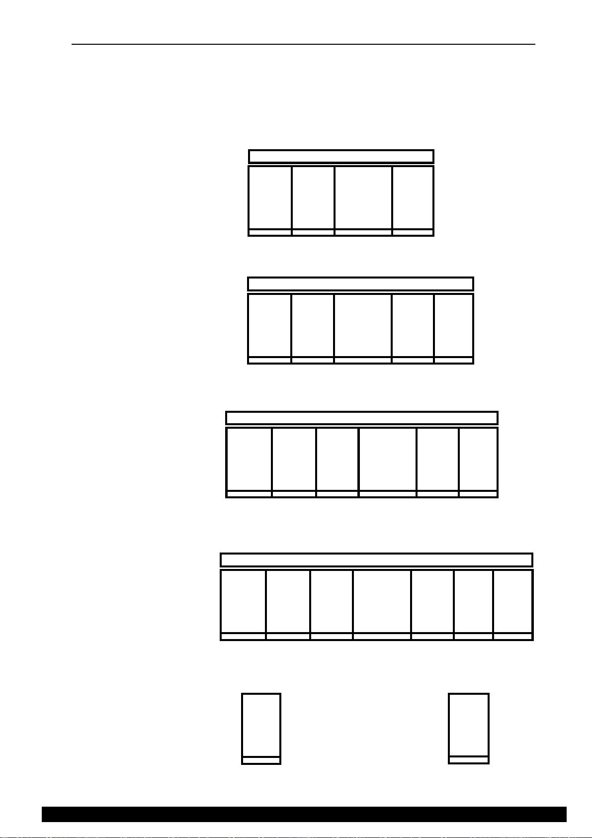
STANDARD CONSOLES
All consoles supplied with separate RPS11 rack mount power unit.
Optional RPSD dual supply combiner / monitor.
Optional VU meterpod and optional SYS-LINK expander system.
GL4000-824S
GL4000M-824n
GL4000-832S
GL4000M-832n
GL4000-840S
GL4000M-840n
CHANS
1-8
CHANS
1-8
M24 VU METERBRIDGE
CHANS
9-16
M32 VU METERBRIDGE
CHANS
9-16
M40 VU METERBRIDGE
MASTER
MASTER
CHANS
17-24
CHANS
17-24
CHANS
25-32
GL4000-848S
GL4000M-848n
GL4000-8M
CHANS
1-8
CHANS
1-8
MONO
CHANS
8x
CHANS
9-16
CHANS
9-16
CHANS
17-24
M48 VU METERBRIDGE
CHANS
17-24
MASTER
MASTER
GL4000-4SM
CHANS
25-32
CHANS
25-32
CHANS
33-40
CHANS
33-40
4x
MONO
4x
STEREO
CHANS
CHANS
41-48
L4DSM2
Section A - 3
ALLEN & HEATH
Page 8
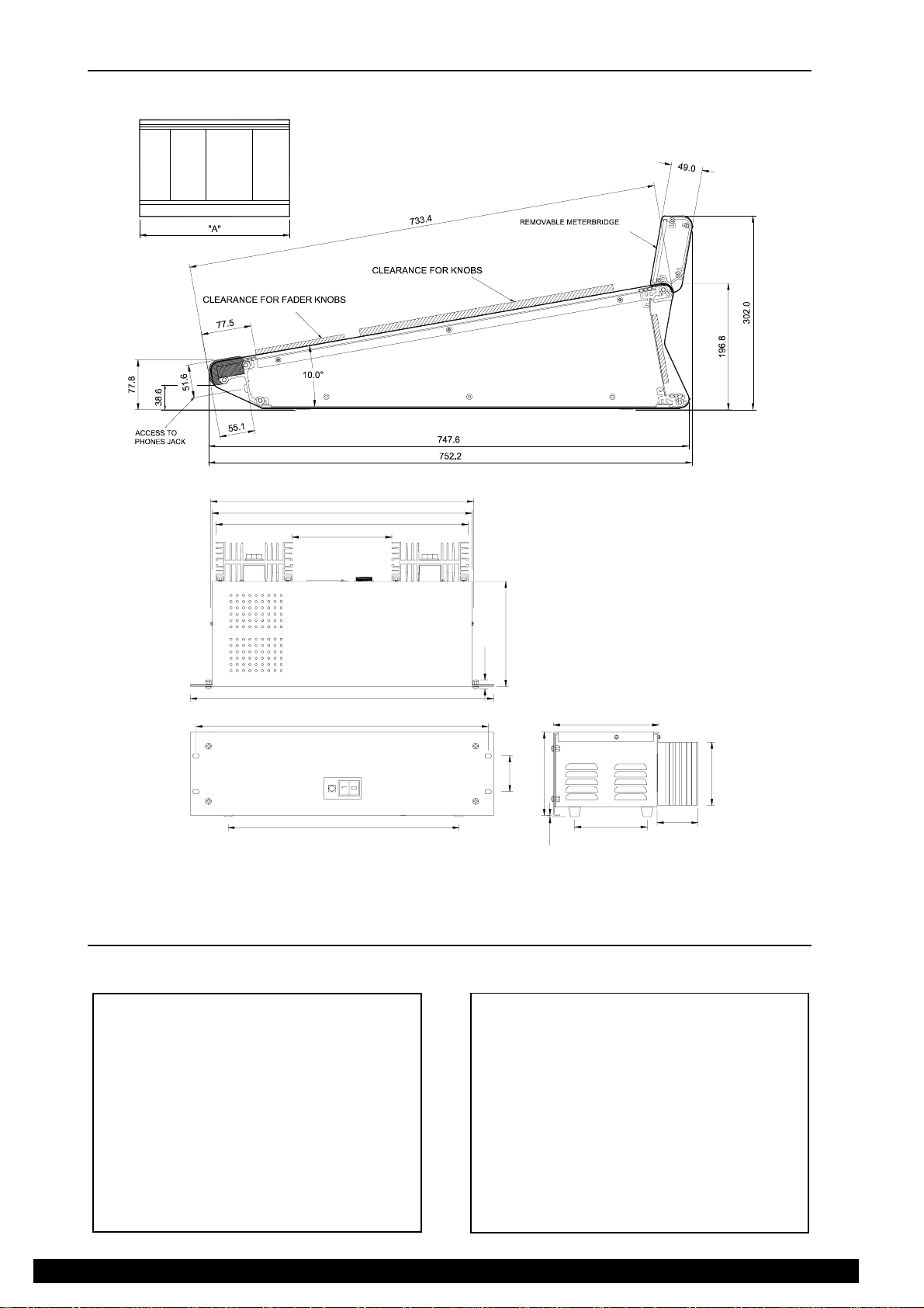
GL4000 DIMENSIONS (consoles up to serial number 403420)
The diagrams below give the dimensions for flightcasing the console and power supply unit.
418.7
413.4
401.3
158.3
167.1
14.2
482.6
465.1
367.6
57.2
132.5
2.0
167.1
115.2
100.0
64.7
The RPS11 is supplied with a 2m mains lead with a moulded mains plug and IEC socket. A3m DC output cable is also
supplied to connect the RPS11 to the GL4000.
MECHANICAL DETAILS
UNPACKED Width Depth Height Wt
GL4000-824 1166 748 197 43 kg
GL4000-832 1421 748 197 52 kg
GL4000-840 1676 748 197 61 kg
PACKED Width Depth Height Wt
GL4000-824 1702 900 390 76 kg
GL4000-832 1702 900 390 84 kg
GL4000-840 1950 900 390 92 kg
GL4000-848 1931 748 197 70 kg
GL4000-8M 255 748 197 9 kg
Meterpod 1154-1664 +56 +106
RPS11 483 (19") 232 135 (3U) 10 kg
RPSD2 483 (19") 180 45 (1U) 4.5kg
ALLEN & HEATH
Section A - 4
GL4000-848 2205 900 390 120 kg
GL4000-8M 480 830 260 12 kg
Meterpod 1290-1800 130 230 6-8 kg
RPS11 575 295 175 11 kg
RPSD2 570 340 75 6 kg
L4DSM2
Page 9
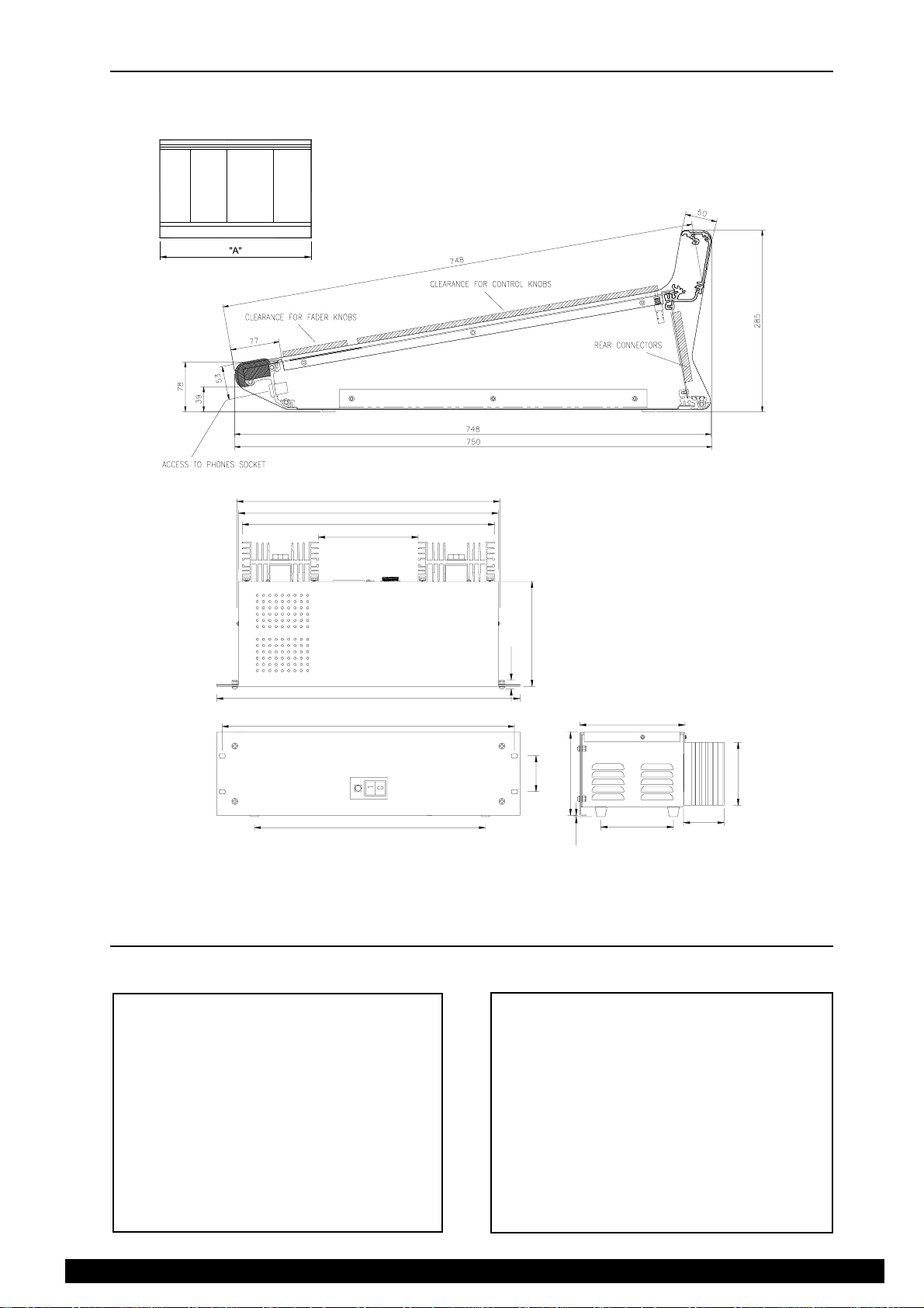
GL4000M DIMENSIONS (consoles from serial number 403421)
The diagrams below give the dimensions for flightcasing the console and power supply unit.
418.7
413.4
401.3
158.3
167.1
14.2
482.6
465.1
367.6
57.2
132.5
2.0
167.1
115.2
100.0
64.7
The RPS11 is supplied with a 2m mains lead with a moulded mains plug and IEC socket. A3m DC output cable is also supplied
to connect the RPS11 to the GL4000.
MECHANICAL DETAILS
UNPACKED Width Depth Height Wt
GL4000M-824 1166 748 285 47 kg
GL4000M-832 1421 748 285 57 kg
GL4000M-840 1676 748 285 67 kg
PACKED Width Depth Height Wt
GL4000M-824 1702 900 390 82 kg
GL4000M-832 1702 900 390 91 kg
GL4000M-840 1950 900 390 100 kg
GL4000M-848 1931 748 285 77 kg
GL4000-8M 255 748 285 9 kg
RPS11 483 (19") 232 135 (3U) 10 kg
RPSD2 483 (19") 180 45 (1U) 4.5kg
L4DSM2
GL4000M-848 1931 900 390 129 kg
GL4000-8M 480 830 260 12 kg
RPS11 575 295 175 11 kg
RPSD2 570 340 75 6 kg
Section A - 5
ALLEN & HEATH
Page 10

SPECIFICATIONS
0dBu = 0.775 Vrms Reference for high level equipment +4dBu =
1.23 V
0dBV = 1 Vrms Reference for low level equipment -10dBV = 310 mV
0VU meter reading = +4dBu at XLR outputs
Input Gain
Mic/Line Input ............................................ +6dB to +60dB variable
Mic/Line + Pad ............................................ -14dB to +40dB variable
Line Input ............................................ -14dB to +40dB variable
Stereo Line Input ........................................... off to +10dB variable
2-track Return ............................................ off to +10dB variable
Maximum Output Level
Main Outputs ............................................ +27dBu into load of >600 ohm
Jack Outputs ............................................ +21dBu into load of >2K ohm
Internal headroom ......................................... +21dB
Frequency Response
Measured 20Hz to 20kHz ref 1kHz
Mic to mix (+40dB) ....................................... +0/-0.5dB
Line to mix (0dB) ........................................... +0/-0.5dB
Distortion
THD + noise measured @ 1kHz +20dBu
Mic to mix (+40dB) ....................................... 0.006%
Line to mix (0dB) ........................................... 0.006%
Crosstalk
Referred to driven channel @ 1kHz
Channel to channel ....................................... > 100dB
Mute shutoff ............................................ > 85dB
Fader shutoff ............................................ > 90dB
Noise Performance
Measured rms 22Hz to 22kHz bandwidth
Mic EIN ............................................ -128dB 150 ohm source
Line pre-amp (0dB) ........................................ < -91dBu
Residual output noise .................................... < -98dBu (-102dB S/N)
Mix noise, nothing routed .............................. < -87dBu (-91dB S/N)
Mix noise, 24 channels routed ...................... < -81dBu (-85dB S/N)
Metering
Input meters ............................................ 4 segment LED (signal, 0, +6, peak)
Mix meters ............................................ 4 segment LED (signal, 0, +6, peak)
Output meters ............................................ 12 segment LED
LED meter response ..................................... peak reading
Peak indicators ............................................ on 5dB before clipping
Signal indicators ........................................... on -20dBu
VU meterpod ............................................ Illuminated VU moving coil meters
ALLEN & HEATH
Section A - 6
L4DSM2
Page 11
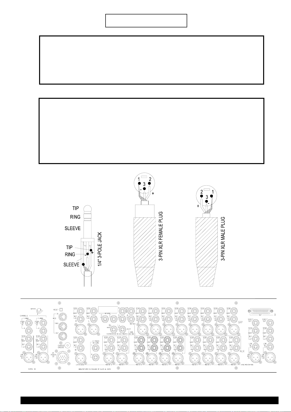
CONNECTIONS
INPUTS:
MIC/LINE IN .................. XLR ........................... pin 2 hot, 3 cold ........... balanced ......... 2 kohms .......... variable -60 to -6dBu
MIC/LINE IN +PAD ........ XLR ........................... pin 2 hot, 3 cold ........... balanced ......... 10 kohms ........variable -40 to +14dBu
LINE IN .......................... 1/4" JACK .................. tip hot, ring cold ........... balanced ......... 10 kohms ........ variable -40 to +14dBu
STEREO LINE IN .......... 1/4" JACK .................. tip hot, ring cold ........... balanced ......... 10 kohms ........ -10dBu or +14dBu
CHANNEL INSERTS ..... 1/4" JACK .................. tip hot, ring cold ........... balanced ......... 10 kohms ........ 0dBu
OUTPUT INSERT RET . 1/4" JACK .................. tip hot, ring cold ........... balanced ......... 10 kohms ........ -2dBu
2-TRACK INPUT ........... 1/4" JACK ......................................................... unbalanced ..... 10 kohms ........ variable -10dBV
OUTPUTS:
L, R, MONO OUT, ......... XLR ........................... pin 2 hot, 3 cold ........... balanced ......... 75 ohms .......... +4dBu
GROUP OUT, ................XLR ........................... pin 2 hot, 3 cold ........... balanced ......... 75 ohms .......... +4dBu
AUX OUT, ...................... XLR ........................... pin 2 hot, 3 cold ........... balanced ......... 75 ohms .......... +4dBu
MATRIX A, B, C, D ........ 1/4" JACK .................. tip hot, ring cold ........... impedence bal 50 ohms .......... +4dBu
DIRECT OUT ................. 1/4" JACK .................. tip hot, ring cold ........... impedence bal 50 ohms .......... 0dBu or variable
MONITOR ...................... 1/4" JACK .................. tip hot, .......................... unbalanced ..... 2 kohms .......... 0dBu variable
2-TRACK OUTPUTS .....1/4" JACK.................. tip hot, .......................... unbalanced ............................... 0dBu variable
HEADPHONES OUT ..... 1/4" JACK ................. tip L, ring R .................. for stereo headphones 8 to 400 ohms
( 2 SOCKETS) ............... 1/4" JACK ................. tip L, ring R .................. for stereo headphones 8 to 400 ohms
L4DSM2
GL4000 REAR PANEL CONNECTORS
Section A - 7
ALLEN & HEATH
Page 12
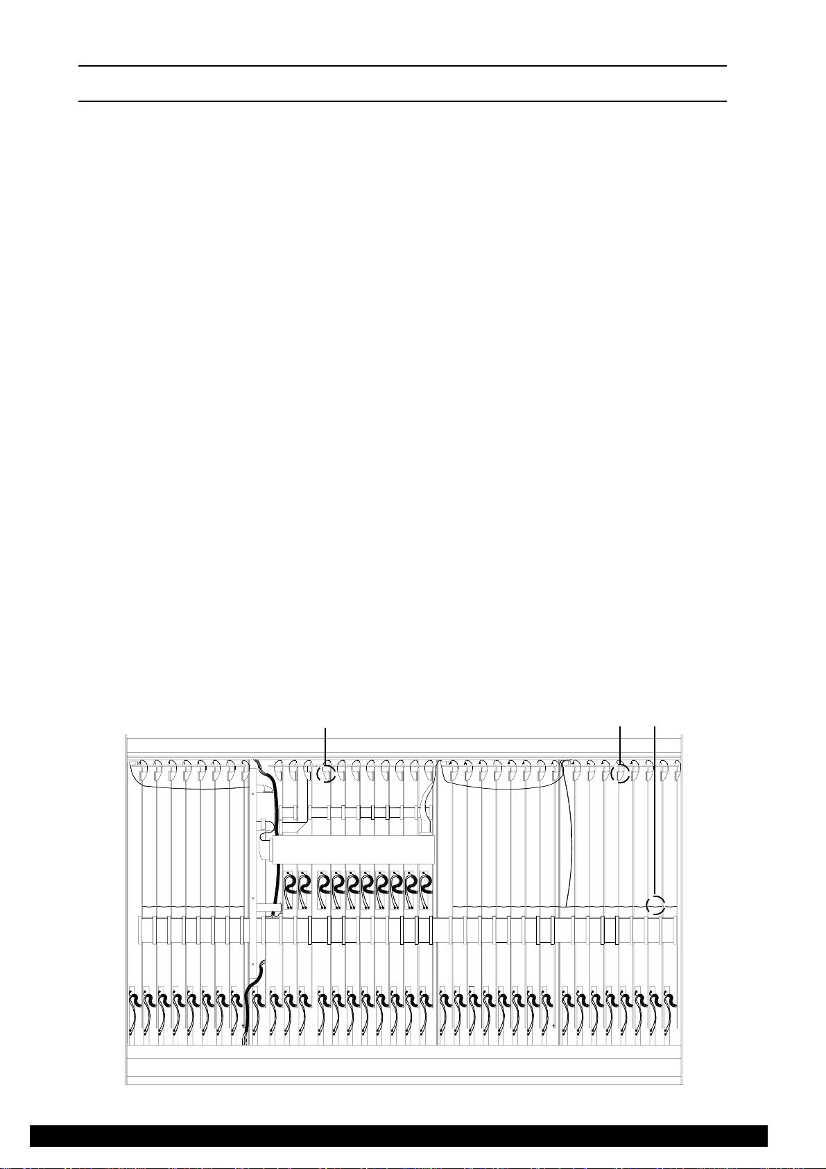
REMOVING A CHANNEL, GROUP, LEFT / RIGHT, MONO or MASTER
CIRCUIT BOARD ASSEMBLY
Before beginning any service work, remove all power to the console and disconnect any signal cables where necessary.
Service work is best carried out with the console inverted or positioned upright on its rear with the connectors removed.
Ensure adequate lighting and use the correct tools. Access to the CHANNEL, GROUP, LEFT/RIGHT, MONO or
MASTER circuit board is as follows:
1.) Before inverting the console, pull off the knobs and remove the pot nuts from the circuit assembly to be
removed. The switch caps can remain in place.
2.) With the console inverted or on its rear, remove the base and identify the circuit board to be removed.
3.) Disconnect the harness (A) plugged into the connectors mounted along the edge of the circuit boards..
4.) Carefully unplug the flat flexible cable (B) plugged into the circuit board asssembly to be removed.
WHEN REMOVING A CHANNEL CIRCUIT BOARD ASSEMBLY
Cut the Earth buss wire (G) on each side of the channel circuit board to be removed. Remember to resolder
the Earth buss wire (G) wire when channel circuit board has been replaced.
WHEN REMOVING A GROUP, LEFT/RIGHT or MONO CIRCUIT BOARD ASSEMBLY
The SLAVE circuit board assembly mounted across the GROUP, LEFT, RIGHT and MONO circuit board
assemblies in the master section of the console will have to be removed along with harness (D).
ALSO WHEN REMOVING THE RIGHT CIRCUIT BOARD ASSEMBLY
Harness (E) will have to be disconnected from the MONO circuit board along with harness (D).
ALSO WHEN REMOVING THE MONO CIRCUIT BOARD ASSEMBLY
Harness (E) and the flexible flat cable (F) will have to be disconnected from the MONO circuit board along
with harness (D). Take care not to stretch the DC power harness and fader wires still connected to the circuit
board assembly.
WHEN REMOVING THE MASTER CIRCUIT BOARD ASSEMBLY
The SLAVE circuit board assembly can remain in place, only harness (C) requires removal from both the
SLAVE and MASTER circuit board assemblies. The flexible flat cable, (F) and the green wire soldered onto
the trackside of the cicuit board will also need to be disconnected. Take care not to stretch the headphone
socket wires that are still connected.
5.) The circuit board can now be removed, take care not to stretch the fader wires that are still connected.
When all service work is complete, remove all debris such as solder, component legs and wire clippings from inside the
console and check your work carefully before reassembly. To refit the circuit assembly follow the above procedure in
reverse order. Make sure all harnesses are correctly aligned and plugged on. Test for correct operation.
B
B
CONSOLE REAR
E
D
C
SLAVE PCB
G
ALLEN & HEATH
F
A
CONSOLE FRONT
GL4000-824 inverted with the base cover removed.
Section A - 8
L4DSM2
Page 13
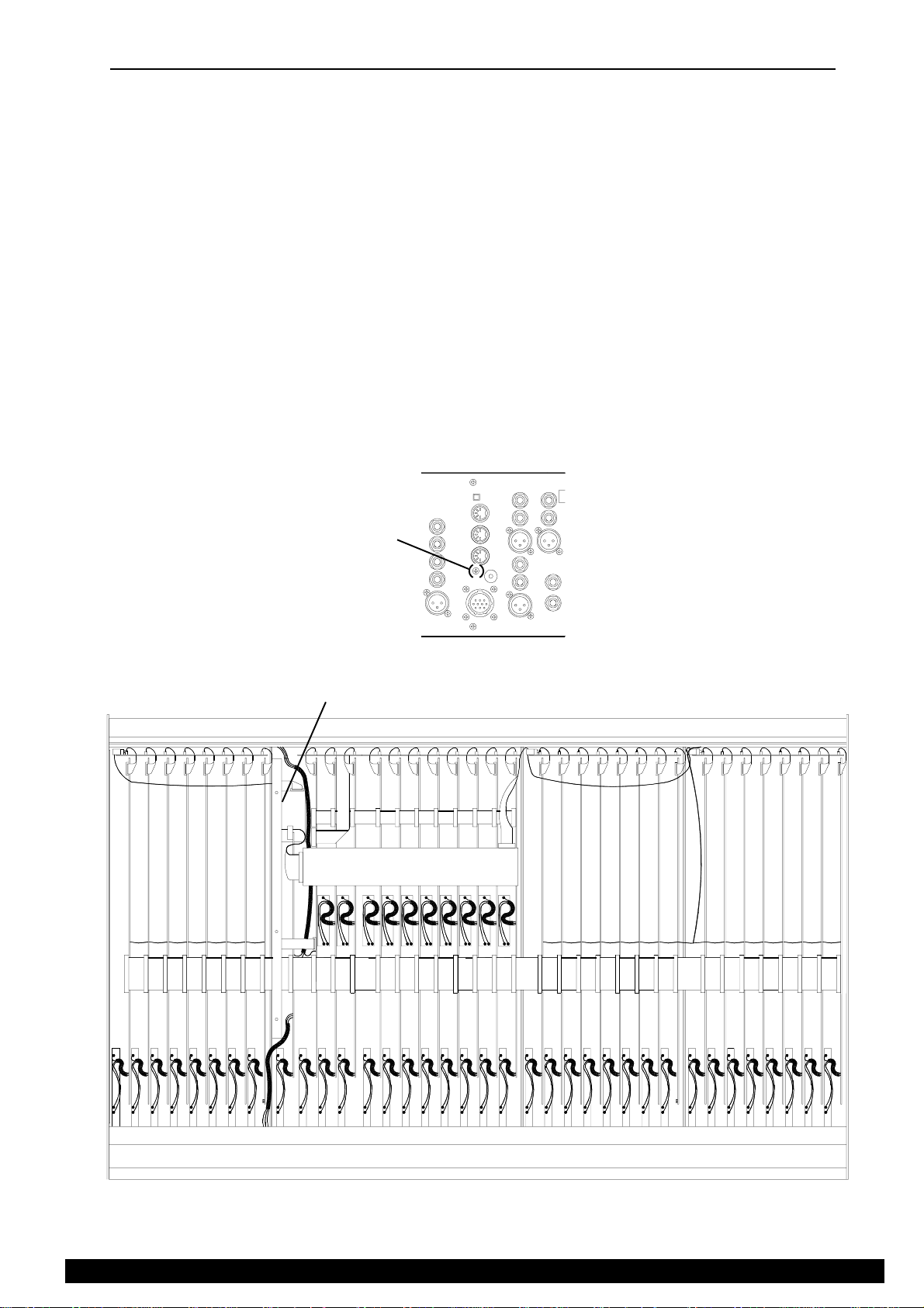
REMOVING THE MICRO CIRCUIT BOARD ASSEMBLY
Before beginning any service work remove all power to the console and disconnect any signal cables where necessary.
Service work is best carried out with the console inverted or positioned upright on its rear with the connectors removed.
Ensure adequate lighting and use the correct tools. Access to the MICRO circuit board is as follows:
1.) Working from the rear of the console, remove the screw (A) near to the CHASSIS GROUND terminal on the
rear connector panel.
2.) With the console inverted or on its rear, remove the base, identify the MICRO circuit board assembly and then
disconnect the ribbon harnesses plugged into the connectors mounted along the edge of the circuit board. Also
disconnect the flat flexible cable.
3.) The circuit board can now be removed by first squeezing the tops of the mounting pillars and lifting the circuit
board clear of the pillars. Then carefully manoeuvre the circuit board assembly into a suitable position to carry
out service work. Take care not to stretch the wires soldered onto the circuit board
When all service work is complete, remove all debris such as solder, component legs and wire clippings from inside the
console and check your work carefully before reassembly. To refit the MICRO circuit board assembly follow the above
procedure in reverse order. Make sure all harnesses are correctly aligned and plugged on. Test for correct operation.
rear panel view
MICRO PCB
Ù
A
CONSOLE REAR
L4DSM2
CONSOLE FRONT
GL4000-824 inverted with the base cover removed.
Section A - 9
ALLEN & HEATH
Page 14
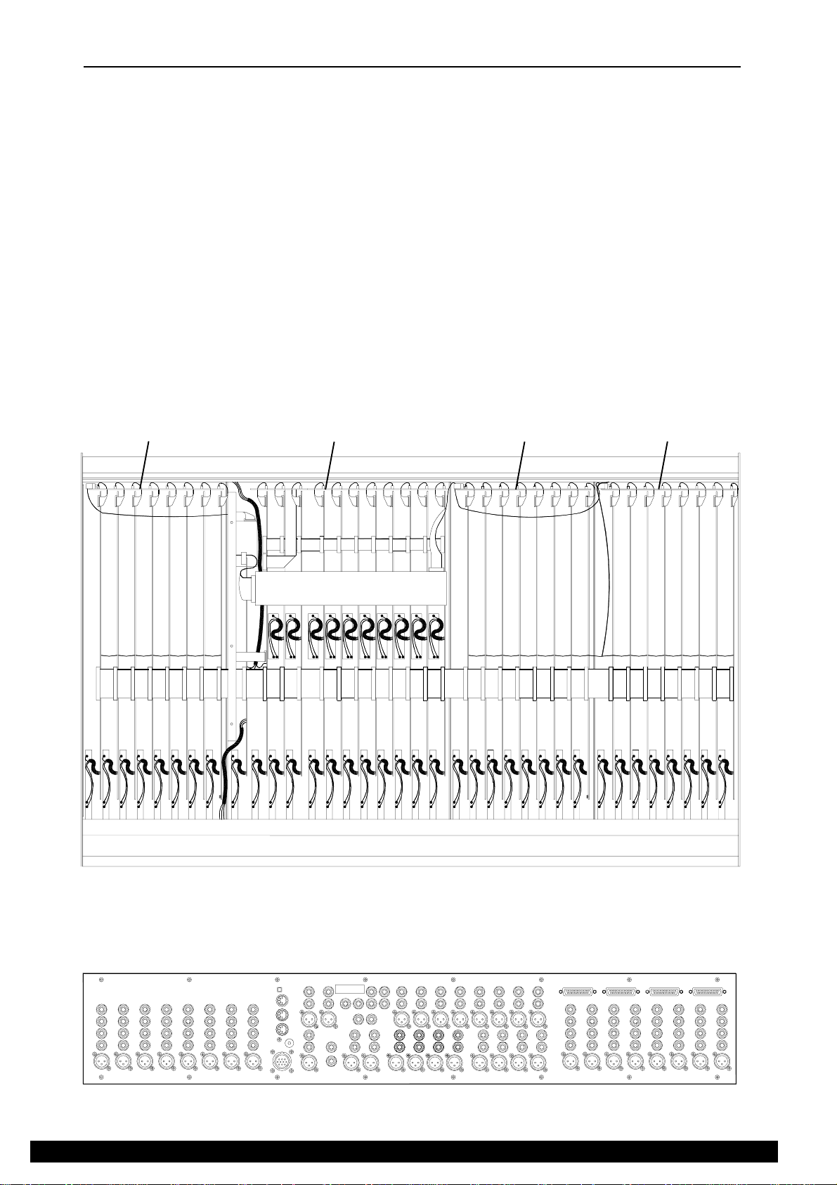
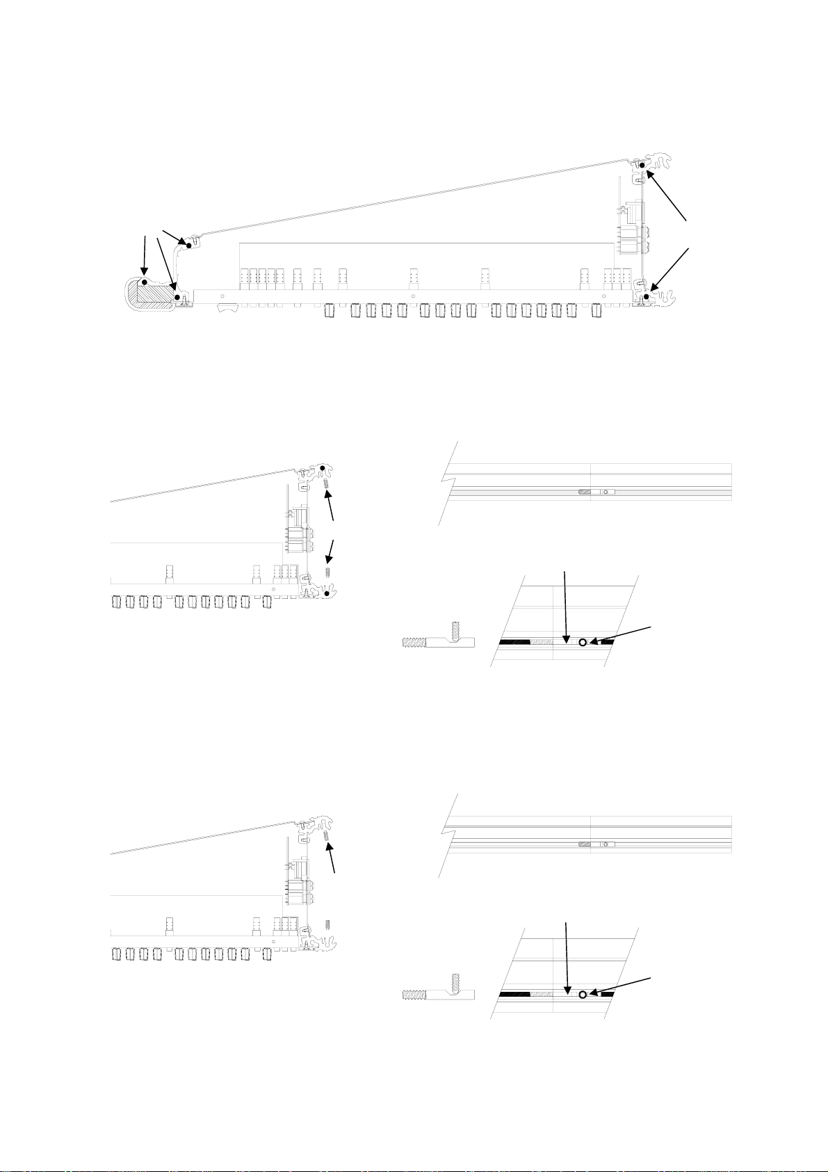
REMOVING A CONNECTOR CIRCUIT BOARD ASSEMBLY
Before beginning any service work, remove all power to the console and disconnect any signal cables where necessary.
Service work is best carried out with the console inverted on a clean work surface suitably covered to protect the console
cosmetics. Ensure adequate lighting and use the correct tools. Access to the connector circuit boards is as follows:
1.) With the console inverted, remove the base. Identify which connector board is to be removed and then
disconnect the flat flexible cables and ribbon harnesses to it.
2.) Working from the rear of the console remove the screws (A) fixing the XLR connectors to the panel but do
not remove the screws (B) fixing the panel to the chassis. Remove the 12mm hex jack nuts (C) with a suitable
tool.
3.) The circuit board assembly can now be removed from the rear panel.
NOTE: if removing a master connector circuit board assembly, unscrew the green earth wires connecting the
circuit board assembly to the chassis extrusion before lifting the circuit board clear.
When all service work is complete, remove all debris such as solder, component legs and wire clippings from inside the
console and check your work carefully before reassembly. To refit the connector circuit assembly follow the above
procedure in reverse order. Make sure all harnesses are correctly aligned and plugged on. Test for correct operation.
INPUT CONNECTOR
CIRCUIT BOARD
ASSEMBLY
MASTER CONNECTOR
CIRCUIT BOARD
ASSEMBLY
INPUT CONNECTOR
CIRCUIT BOARD
ASSEMBLY
INPUT CONNECTOR
CIRCUIT BOARD
ASSEMBLY
INPUT SECTION
ALLEN & HEATH
CONSOLE FRONT
GL4000-824 inverted with the base cover removed.
MASTER SECTION
GL4000 Rear Panel View.
Section A - 10
INPUT SECTION
B
C
C
C
C
A
A
B
L4DSM2
Page 15
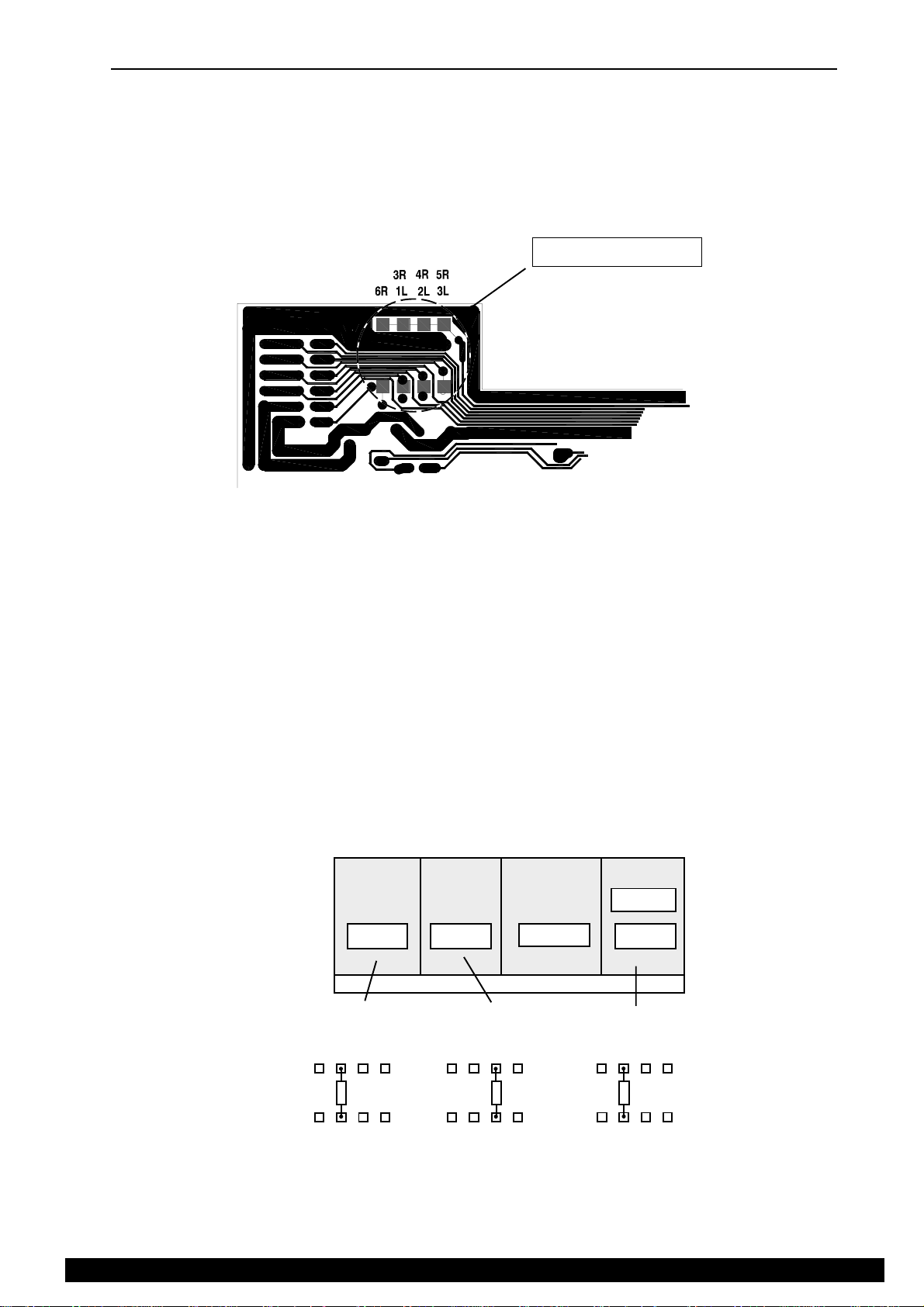
ASSIGNING AN INPUT CONNECTOR CIRCUIT BOARD ASSEMBLY
Before fitting a replacement input connector circuit board assembly, check the assignment of the channel mutes is
correct. If possible check the circuit board assembly with the one that has been removed.
The assignment links are zero ohm (0R) resistors and are located near to the ribbon harness connector on the input
connector board.
The channel mute assignment is set by soldering a 0R resistor into one of four locations. see below
Assignment links
Input connector
circuit board
track side view
The diagrams below show the channel mute link assignments for the input connector circuit board assemblies for each
console format.
Remember when adding an expander to the console the assignment of the links in the console may also require
reassigning. Refer to the expander fitting instructions (AP2794).
GL4000-824S
GL4000M-824n
(Stereo configurations differ)
stereo
6R
17 - 24
4R
3R
2L
1L
5R
3L
3R
1L
1 - 8
4R
2L
5R
3L
9 - 16
3R
6R6R
1L
4R
2L
MASTER
5R
3L
L4DSM2
Section A - 11
ALLEN & HEATH
Page 16
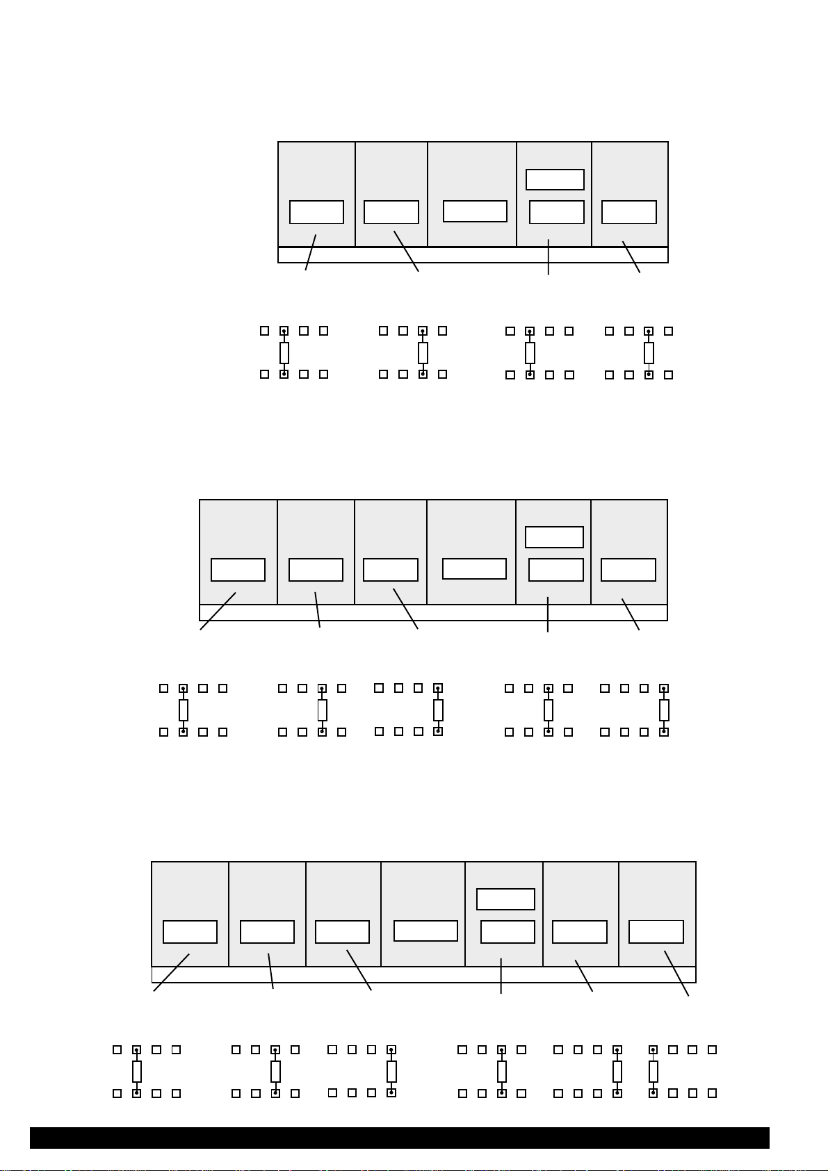
GL4000-832S
GL4000M-832n
(Stereo configurations differ)
stereo
GL4000-840S
GL4000M-840n
(Stereo configurations differ)
1 - 8
6R
3R
1L
1 - 8
4R
2L
9 - 16
5R
3L
9 - 16
3R
6R
1L
17 - 24
4R
2L
MASTER
5R
3L
MASTER
6R
17 - 24
4R
3R
2L
1L
stereo
25 - 32
5R
3L
25 - 32
3R
6R
1L
33 - 40
4R
2L
5R
3L
5R
4R
3R
6R
1L
2L
3L
GL4000-848S
GL4000M-848n
(Stereo configurations differ)
1 - 8
5R
4R
3R
6R
1L
2L
3L
9 -16
3R
1L
4R
2L
5R
3L
3R
1L
5R
4R
3L
2L
17 - 24
6R
3R
1L
6R
4R
2L
4R
3R
2L
1L
MASTER
5R
3L
5R
3L
6R
stereo
25 - 32
3R
4R
1L
2L6R
6R
5R
3L
3R
1L
4R
2L6R
6R
5R
3L
33 - 40
4R
3R
2L
1L
6R
5R
3L
3R
1L
5R
4R
3L
2L
41 - 48
3R
6R
1L
4R
2L
5R
3L
ALLEN & HEATH
Section A - 12
L4DSM2
Page 17
INTERNAL LINK OPTIONS
The GL4000 is configured to satisfy most of the applications that are likely be encountered. However, the following
internal link options are offered for those applications that may require alternative settings. These options require access
to the internal circuit assemblies and resoldering of circuit board links. This work should be carried out by technically
competent personnel. Further information is available in the separately available service manual and from your Allen
& Heath agent.
MONO CHANNEL
Set individual aux sends to be permanently pre-fader or post-fader rather than switched. Re-position wire links. Set the
pre-fade aux sends to be pre-EQ rather than post-EQ. Re-position a wire link. Set the pre-fade aux links to be pre-mute
rather than post-mute. Re-position a wire link. Disable +48V phantom power so that the panel switch has no effect. Cut
out the wire link.
AUX1AUX2AUX3
EQ
POST-FADE
PRE-FADE
SWITCHED
MONO INPUT
PRE-MUTE
POST-MUTE
PRE-FADE AUX OPTIONS
POST-EQ
PRE-EQ
+48V PHANTOM POWER
ENABLE
STEREO CHANNEL
Set individual aux sends to be permanently pre-fader or post-fader rather than switched. Re-position wire links. Set the
pre-fade aux sends to be pre-EQ rather than post-EQ. Re-position 2 wire links. Set the pre-fade aux links to be pre-mute
rather than post-mute. Re-position a wire link. Disable +48V phantom power so that the panel switch has no effect. Cut
out the wire link.
PRE-MUTE
POST-MUTE
POST-FADE
SWITCHED
PRE-EQ
POST-EQ
PRE-FADE AUX OPTIONS
AUX1AUX2
EQ
PRE-FADE
PRE-EQ
LR
POST-EQ
STEREO INPUT
+48V PHANTOM POWER
ENABLE
TALKBACK MIC +48V
Disable +48V phantom power from the TB mic input XLR. Remove a jumper link (fit on 1 pin to keep in console).
TB MIC IN
L4DSM2
TALKBACK
Section A - 13
TALKBACK MIC
PHANTOM POWER
+48V ENABLE
ALLEN & HEATH
Page 18

ORDERING SPARE PARTS
ORDERING A CONSOLE
To order a new console please specify the model number required. Refer to the section: Standard Consoles for more detail
MODEL DESCRIPTION ORDER CODE
GL4000M-824A/B/C/D 24 Input channels with integral meterbridge + Power Supply GL4000M-824n
GL4000M-832A/B/C/D/E 28 Input channels with integral meterbridge + Power Supply GL4000M-832n
GL4000M-840A/B/C/D 36 Input channels with integral meterbridge + Power Supply GL4000M-840n
GL4000M-848A/B/C/D/E/F 44 Input channels with integral meterbridge + Power Supply GL4000M-848n
ORDERING AN OPTION
To order an option please specify the model number required:
GL4000-M24 Meterpod to fit 24 channel console GL4000-M24
GL4000-M32 Meterpod to fit 32 channel console GL4000-M32
GL4000-M40 Meterpod to fit 40 channel console GL4000-M40
GL4000-M48 Meterpod to fit 48 channel console GL4000-M48
GL4000-8M 8 Mono Input channel expander GL4000-8M
GL4000-4SM 4 Mono + 4 Stereo Input channel expander GL4000-4SM
GL4000-SL1 GL4000 SYS-LINK kit GL4000-SL1
RPSD2 Dual supply Combiner / Monitor RPSD-2
MANUALS AND SUPPORT DOCUMENTATION
DESCRIPTION ORDER CODE
GL4000 Brochure AP2641
GL4000 User Guide AP2642
GL4000 Service Manual AP2640
GL4000 Meterpod Fitting Instructions AP2126
GL4000 SYS-LINK Fitting Instructions AP2786
GL4000 SYS-LINK Application Note AP2787
GL4000-8M / 4SM Fitting Instructions AP2794
RPS11 User / Installation Guide AP2725
RPSD-2 & RPSD User / Installation Guide AP2263
SOFTWARE EPROM
To order a replacement EPROM, please contact ALLEN & HEATH and notify us of your console serial number, its present
EPROM version and code number and reason for the replacement.
GL4000 software
SERVICE TOOLS
The tools required to service the GL4000 are standard to an electronics service workshop and are easily obtainable. The
following items are necessary for disassembly and service access:
ALLEN & HEATH
4mm Hexagon (Allen) key (M6 side trim) AT0033
1-point Crosshead screwdriver (M3, 4AB) AT0004
2-point Crosshead screwdriver (M4, 6AB) AT0004
11mm Nutdriver (potentiometer nuts, headphone socket nuts)
12mm Nutdriver (jack nuts)
Torx-headed screw drivers
Section A - 14
L4DSM2
Page 19

ORDERING AN ASSEMBLY
The following assemblies are supplied fully tested. Please note that several of these need to be assigned according to
their position in the console. This is done by soldering wire links or assignment pads. It is best to check the assignment
settings of the assembly you are replacing before removing it from the console. Please quote the description and order
code for the part required.
Printed circuit (PCB) assemblies:
Mono Input Connector IN-8M CONN PCB assembly* 002-161
Mono Input PCB assembly 002-160
Stereo Input Connector IN-4SM CONN PCB assembly* 002-196
Stereo Input PCB assembly 002-195
Group 1-4 PCB assembly*+ 002-162
Group 5-8 PCB assembly*+ 002-163
Left / Right PCB assembly*+ 002-197
Master PCB assembly 002-165
Master connector PCB assembly 002-166
Mono PCB assembly 002-164
Slave PCB assembly 002-167
MPU & 3 digit display PCB assembly 002-198
RPS11 PCB assembly 002-047
GL4000 Meterpod PCB assembly LEFT 002-039
GL4000 Meterpod PCB assembly RIGHT 002-040
GL4000M Meterpod PCB assembly LEFT 002-464
GL4000M Meterpod PCB assembly RIGHT 002-465
* Requires assignment + Quote Group Number, Left or Right
IDC connector harnesses:
GL4000-824/32/40 & 48 40 way Main harness AL2636
GL4000-824 & 832 16 way left hand harness AL2763
GL4000-840 & 848 16 way left hand harness AL2764
GL4000-816 & 824 16 way right hand harness AL2760
GL4000-832 & 840 16 way right hand harness AL2761
GL4000-848 16 way right hand harness AL2762
GL4000 (all formats) 16 way Master harness AL2759
GL4000 (all formats) 16 way Meter harness AL2733
GL4000 (all formats) 26 way MPU harness AL2732
THE CHASSIS TRIM
GL4000 (all formats) Left & Right Chassis side trims AA2089L/R
GL4000M (all formats) Left & Right Chassis side trims AA3584-L/R
Write-on strip 10' AK0327
GL4000-824 & 832 Ident strip CHAN 1-16 AK2637
GL4000-824 & 832 Ident strip CHAN 1-16 Rear AK3112
GL4000-840 & 848 Ident strip CHAN 1-24 AK2638
GL4000-840 & 848 Ident strip CHAN 1-24 Rear AK3113
GL4000-824 & 832 Ident strip GRP 1- CHAN 32 AK2639
GL4000-824 & 832 Ident strip GRP 1- CHAN 32 Rear AK3114
GL4000-840 & 848 Ident strip GRP 1- CHAN 40 AK2703
GL4000-840 & 848 Ident strip GRP 1- CHAN 40 Rear AK3115
GL4000-848 Ident strip CHAN 41-48 AK2704
GL4000-848 Ident strip CHAN 41-48 Rear AK3116
GL4000 Meterpod Left & Right Meterpod side trims AA2090L/R
L4DSM2
Section A - 15
ALLEN & HEATH
Page 20

ORDERING A SPARES KIT
It is recommended that the spares kit order code 002-177 is held and maintained by the service agent to enable in-field
service repairs to the GL4000 independent of the ALLEN & HEATH factory. If you are an existing ALLEN & HEATH
service agent who already stocks the spares kit for the ALLEN & HEATH GL4, you may already stock some of the common
parts. A TOP-UP kit 002-178 is available which provides just the parts unique to the GL4000 range. Commonly available
items such as resistors, capacitors, tools and soldering equipment are not included. The contents of the kit is listed below
and is supplied in a cabinet of drawers. Individual spare parts may be ordered. Please quote the description and order
code for the part required.
A - GL4000 STANDARD SPARES KIT
B - GL4 TO GL4000 TOP-UP KIT
AB
DESCRIPTION ORDER CODE QTY QTY
Fixings:
Screw 4AB x 5/16" Pan Pozi Black AB0057 10 Screw 4AB x 5/16" CSK Pozi Black AB0059 10 Screw 6B x 5/16" Pan Pozi Black AB2084 10 Screw 8B x 5/16" CSK Pozi Black AB2085 10 Screw 6B x 1/4" CSK Pozi zinc AB2083 10 Screw 6B x 3/8" CSK Pozi zinc AB2082 10 Screw M6 x 20mm CSK Allen Black AB0310 5 Screw M3 x 5mm CSK Pozi Black AB0070 10 Screw M3 x 8mm Pan Pozi Black AB0073 10 Screw M3 x 8mm CSK Pozi Black AB0074 5 Nylock Nut M3 AB0102 5 Fixing for D type connector AB2189 10 Joint Block AB0253 2 Plastic pillar snap-in AB2233 4 4
Knobs and caps:
Knob Yellow & Grey 11mm D AJ2079 10 Knob Dark Grey & Grey 11mm D AJ2078 10 Knob Green & Grey 11mm D AJ2077 10 Knob Blue & Grey 11mm D AJ2075 10 Knob Brown & Grey 11mm D AJ2080 10 Knob Red & Grey 11mm D AJ2074 10 Knob Pale blue & Grey 11mm D AJ2076 10 10
Fader Knob 11mm White+Black line Jungpoon* AJ2231 10 10
Fader Knob 11mm Red+White line Jungpoon* AJ2230 5 5
Fader Knob 11mm Yellow+Black line Jungpoon* AJ2232 5 5
Fader Knob 11mm Blue+White line Jungpoon* AJ2663 5 5
Fader Knob 11mm White+Black line Alps* AJ8078 10 Fader Knob 11mm Red+Black line Alps* AJ8079 5 Fader Knob 11mm Yellow+Black line Alps* AJ8080 5 Fader Knob 11mm Blue+Black line Alps* AJ8081 5 Button 5.5mm Square Grey AJ0363 10 Button 5.5mm Square Red AJ0364 10 Button 5.5mm Square White AJ0373 10 Button 10x5mm Rectangular Grey AJ0093 10 Button 10x5mm Rectangular White AJ0094 10 Button 10x5mm Rectangular Black AJ0096 5 Button large illuminated white AJ8107 10 10
* TO FIND OUT IF JUNGPOON OR ALPS K FADERS/FADER KNOBS CHECK CONSOLE SERIAL NUMBER WITH FACTORY
ALLEN & HEATH
Section A - 16
L4DSM2
Page 21

Faders, Potentiometers, switches, and connectors:
10KA fader 100mm Jungpoon* AI2665 5 5
10KA x 2 fader 100mm (stereo) Jungpoon* AI2664 2 2
10KA fader 100mm Alps K* AI8109 5 5
10KA x 2 fader 100mm (stereo) Alps K* AI8110 2 2
10KA fader 60mm AI8054 5 20KK (203K) AI8003 5 20KB x 2 (203B 14mm wide) AI8006 3 3
20KK x 2 (203K 14mm wide) AI8007 5 20KB (203B) centre click AI8004 5 20KB x 2 (203B 14mm wide) centre click AI8064 3 10KC x 2 (103C 14mm wide) AI0150 5 10KAC x 2 (103AC 14mm wide) AI8008 5 200KC x 2 (204C) AI8005 5 200KC x 2 (204C 14mm wide) AI8009 5 Pot Nut 9mm AB8050 10 Switch 2PCO Latching AL0162 5 Switch 2PCO Momentary AL0374 5 Switch 4PCO Latching AL0333 5 Switch 6PCO Latching AL0354 2 2
Jack Socket Vertical PCB Mount + Hex nut AL8082 5 Jack Socket Headphone AL0328 1 XLR 3 Pin Female Vertical PCB Mount AL8074 5 XLR 3 Pin Male Vertical PCB Mount AL8077 5 XLR 4 Pin Female Chassis Mount AL8104 - -
* TO FIND OUT IF JUNGPOON OR ALPS K FADERS/FADER KNOBS CHECK CONSOLE SERIAL NUMBER WITH FACTORY
LEDs and Semiconductors:
LED 5mm T1¾ Red AE0001 2 2
LED 3mm T1 Green AE0085 5 LED 3mm T1 Yellow AE0084 5 LED 3mm T1 Red AE0086 5 LED Bar 4way 2Gn+1Yel+1Rd AE2702 2 2
LED Bar 12way 8Gn+3Yel+1Rd AE2701 2 2
Transistor 2SB737 PNP AE8069 5 Transistor BC549 NPN AE0020 3 Transistor 2N4403 PNP AE0273 5 Transistor BC214 PNP AE0031 3 Transistor J111N FET AE0083 5 Transistor BC637 NPN AE0068 2 2
Transistor BC638 PNP AE0037 2 2
IC NE5532N Dual Op Amp AE0221 5 IC TL072CP Dual Op Amp AE0046 5 IC LM339N Quad Comparator AE0071 2 IC CMOS 4051B AE0118 1 IC CMOS 4053B AE0117 1 IC CMOS 4099B AE0238 1 IC CMOS 74HC259 AE2727 1 1
IC 6N136 Opto isolator AE0222 1 IC TTL 74LS373N AE0140 1 IC TTL 74LS138N AE0248 1 IC Regulator 7805 (+5V DC) AE0308 2 -
L4DSM2
Section A - 17
ALLEN & HEATH
Page 22

POWER SUPPLY:
Lamp Neon AL0200 2 Mains Fuse 20mm T3.15A (UK, EC) AL0464 5 Mains Fuse 20mm T5A (USA) AL2270 5 5
Mains Fuse 20mm T8A (DC) AL0487 5 5
Transformer 320VA AM2720 - Bridge Rectifier 25A 200V AE0239 1 Transistor MJ3001 AE0240 2 Transistor cover (inc. split washers) AK2767 2 2
Thyristor TIC126M AE0272 1 IC Adjustable Regulator 783 (+48V DC) AE0214 2 IC Regulator UA723CN (+/-16V DC) AE0056 2 Fuseholder 20mm Panel Mount AL0578 1 DC cable assembly (10pin plug to 10pin socket)002-223 - DC cable assembly (10pin plug to 5pin XLR) 002-225 - -
RPSD2:
Mains Fuse 20mm T8.0A AL0487 - Mains Filter IEC 10A AL2260 - Mains Outlet IEC 3 Pin AL2261 - Mains Switch Rocker 0-1 AL0587 - LED 5mm T1¾ Tri-colour AE2258 - Zener Diode BZX85 5V6 AE0012 - RPSD2 / RPSD Packing assembly 002-058 - RPSD DC Supply cable (8pin Cinch - 5pin XLR) 002-060 - RPSD2 DC Supply cable (8pin Cinch-10pin fem) 002-227 - IEC Mains Lead 3pin male to female AH2262 - -
METERPOD:
Preset 10K (calibrate) AC0250 - Meter VU+bulb AD3321 2 Bulb (VU meter) AD0013 5 Spacer PCB M3 AB0331 - Screw M6 x 12mm SKT Hex Black (Grub) AB2087 3 Screw M4 x 12mm CSK Hex Black AB2086 10 -
Miscellaneous:
GL4000M-824 Packing assembly 002-474 - GL4000M-832 Packing assembly 002-475 - GL4000M-840 Packing assembly 002-476 - GL4000M-848 Packing assembly 002-477 - Facia 3 digit display AA2726 - Flex cable 12 way 90mm AH2228 5 Flex socket 12 way 90deg AL2226 - Flex socket 12 way straight AL2227 - Ferrite Bead Axial AF0610 - -
ALLEN & HEATH
Section A - 18
L4DSM2
Page 23
SECTION B
FITTING
INSTRUCTIONS
CAUTION !
B
TO AVOID DAMAGE TO INTERNAL COMPONENTS BY
MISHANDLING AND/OR MISCONNECTION, ONLY
TECHNICALLY COMPETENT PERSONNEL SHOULD
ATTEMPT SERVICE WORK ON THIS CONSOLE.
L4DSM2
Section B - 1
ALLEN & HEATH
Page 24
GL4000 Expander
ALLEN&HEATH
Fitting instructions
The GL4000 expander options are designed to attach to either side of the GL4000 console depending on
console format. The expander can be fitted to consoles with the integral meterbridge as well as those consoles
that do not have the integral meterbridge. The expander modules allow a GL4000 console to be expanded up to
a maximum of 48 channels.
Please read the following instructions carefully before attempting to fit the module.
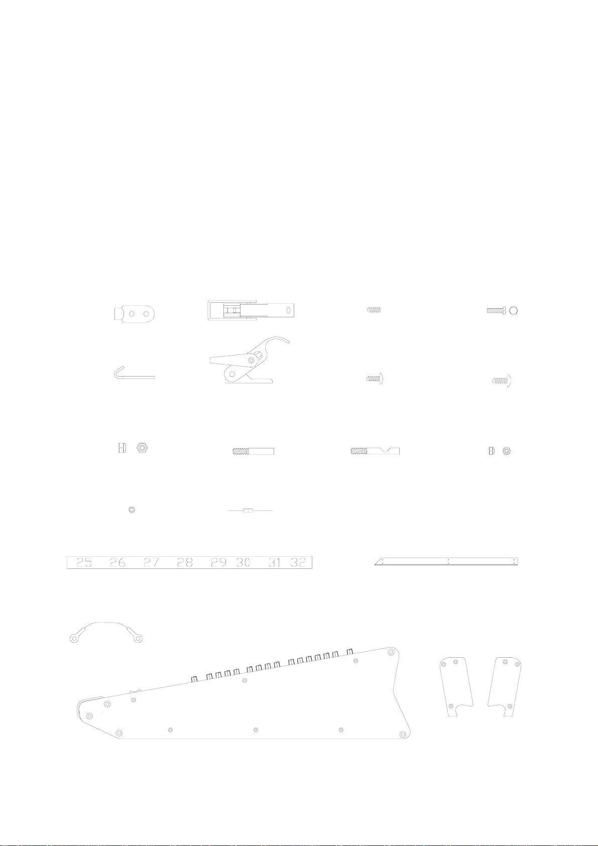
1. Check contents of pack to ensure all parts have been supplied.
A
CATCHPLATE
QUANTITY 1
PART NO. AB0336
G
NUT LOCK M4
QUANTITY 4
PART NO. AB0188
P
SHAKEPROOF WASHER
QUANTITY 3
PART NO. AB0244
IDENT STRIP
L
QUANTITY 1 SET
PART NO.s AK2637 AK2638 AK2639 AK2703 AK2704
AK3112 AK3113 AK3114 AK3115 AK3116
B
ADJUSTABLE FASTENER
QUANTITY 1
PART NO. AB0335
H
STUD M6X38.5
QUANTITY 5
PART NO. AB0325
Q
0R LINK
QUANTITY 5
PART NO. AC0335
C
SCREW M6X8 SKT HEX
QUANTITY 2
PART NO. AB2421
E
SCREW 6BX5/16
QUANTITY 40
PART NO. AB2810
J
STUD SLOTTED
QUANTITY 2
PART NO. AB2406
M
D
SCREW M3X6 HEX
QUANTITY 3
PART NO. AB2813
F
SCREW M4X10
QUANTITY 4
PART NO. AB0271
K
NUT LOCK M3
QUANTITY 3
PART NO. AB0102
BASE BRACKET
QUANTITY 1
PART NO. AA2191
EARTH STRAP
N
QUANTITY 1
PART NO. 002-237
EXPANDER WITH SIDE TRIMS
Allen & Heath AP2794 issue 3 1
SIDE PLATES
R
QUANTITY 1 PAIR
PART NO: AA3849L&R
Page 25
EXPANDER POSITIONING
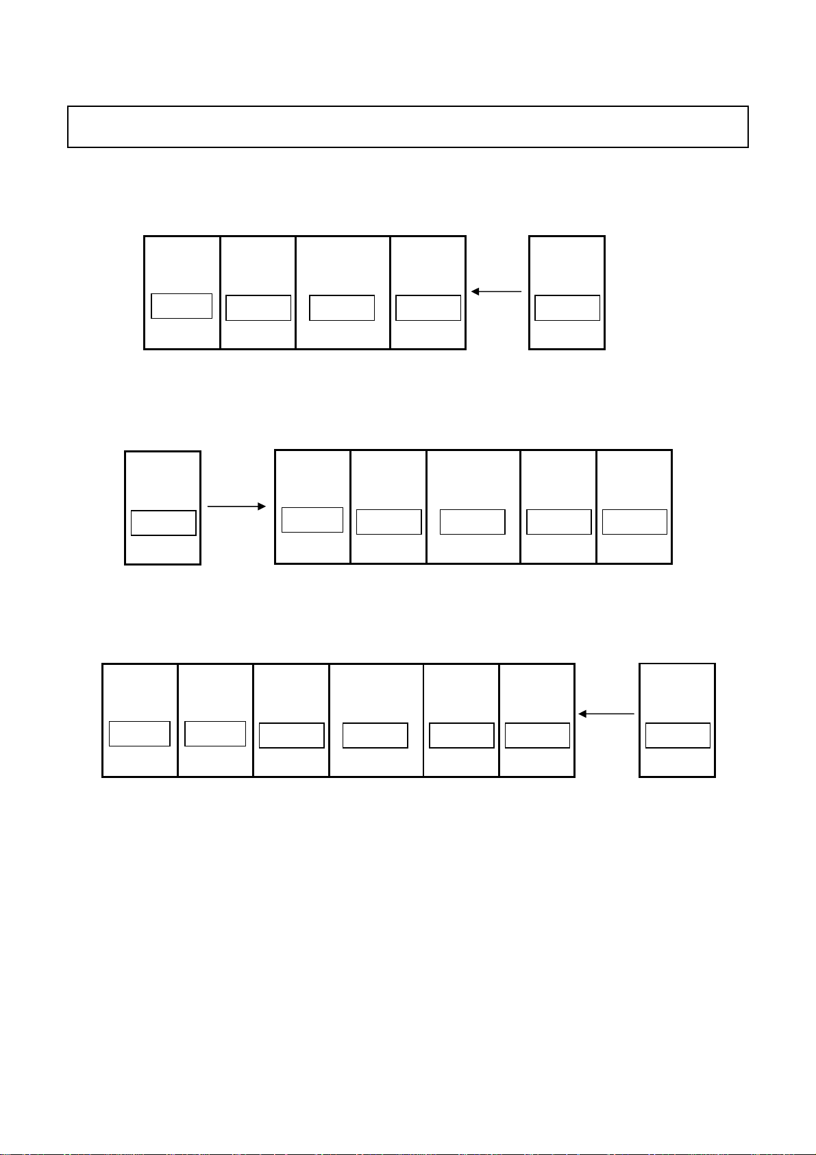
2. The Expander unit must be fitted in the position shown in the diagrams below.
GL4000-824 + Expander
1 - 8
9 - 16 Master Expander 17 - 24
GL4000-832 + Expander
Expander
GL4000-840 + Expander
1 - 8
9 - 16 Master 25 - 32 17 - 24
1 - 8
9 - 16
17 - 24 Master 33 - 40 25 - 32
Expander
TOOLS REQUIRED:
The following tools are required to fit the expander module.
1x 2.5mm Hex key
1x 4mm Hex key
1x 1-point Pozi screwdriver
1x flat point screwdriver
1x long nose pliers
1x 5.5mm AF spanner
1x wire cutters
1x small tipped soldering iron and solder
Allen & Heath AP2794 issue 3 2
Page 26
INSTALLATION
Only technically competent personnel should attempt to fit the expander module.
Disconnect the Power Supply Unit and cables from the console before fitting the
expander module
3. Ensure you have a good work surface and clear area before starting work. Carefully invert the console and
remove the base panel by removing all screws along the edges of the base panel. Also remove the 3 screws
in the centre of the large base panel. Note; do not rest the console on the meterbridge.
4. Remove the side trim and bracket from the side of the console that is to have the expander fitted. Similarly;
remove the side trim and bracket from the side of the expander that is to be joined to the console.
Figure shows console to be expanded on right hand side
Allen & Heath AP2794 issue 3 3
Page 27
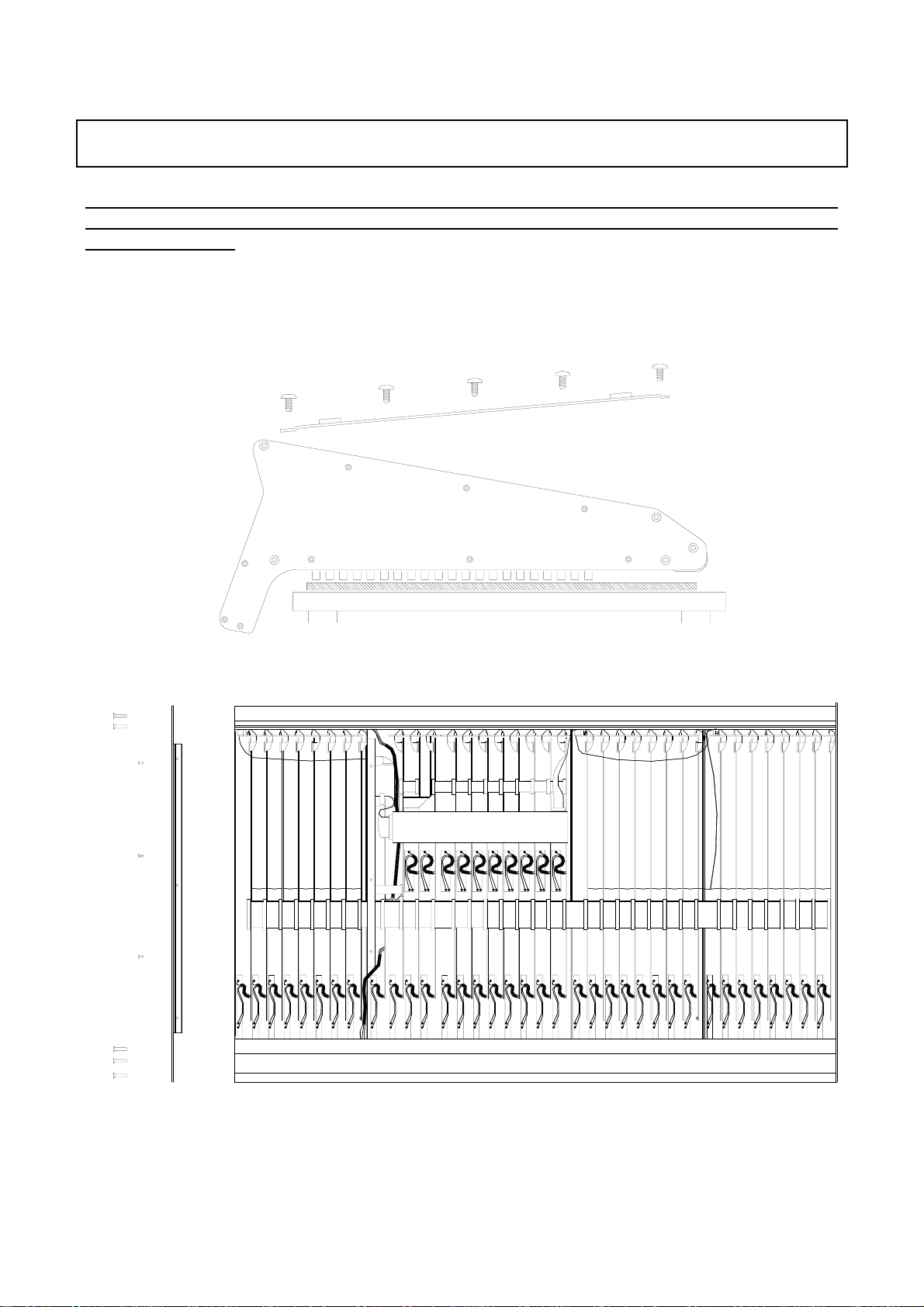
5. Attach the adjustable fastener ‘B’ to the inside of the front extrusion of the console and catchplate ‘A’ to the
inside of the expander using screws
‘F’ and nuts ‘G’. The mounting holes are located under the front
armrest of each unit and are pre-drilled for the adjustable fastener and catchplate. Make sure the movement
of the fastener lever does not interfere with the input channel circuit board assemblies.
Attach adjustable fastener ‘B’
‘
’
console
6. Screw the 2 slotted studs ‘J’ into the upper and lower rear extrusions of the console. Rotate the studs until
the flat is visible in the slots.
J
console
Console with integral meterbridge
6a. Screw the single slotted stud ‘J’ into the lower rear extrusion of the console. Rotate the stud until the flat is
visible in the slot.
J
Console with integral meterbridge
Allen & Heath AP2794 issue 3 4
Page 28
7. Screw the 5 plain studs
‘H’ into the extrusion holes of the expander as shown below.
H
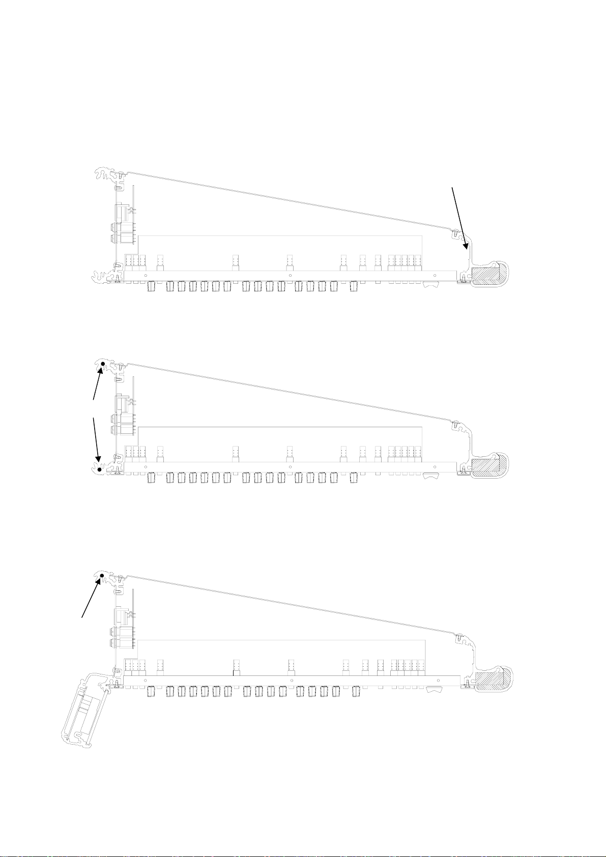
8. Slide the expander module onto the 7 studs and close the adjustable fastener ‘B’ over the catchplate ‘A’,
see 5. The fastener can be adjusted to ensure a good join. Screw in the locking screws
tapped holes of the expander. Make sure the locking screws
expander
H
‘C’ into the pre-
‘C’ engages with the flat of the slotted studs
‘J’, see diagram below.
expander
console expander
C
C
C
J
Console with integral meterbridge
8a. Slide the expander module onto the 6 studs and close the adjustable fastener ‘B’ over the catchplate ‘A’,
see 5. The fastener can be adjusted to ensure a good join. Screw in the locking screw
tapped hole of the expander. Make sure the locking screw
see diagram below.
expander
‘C’ engages with the flat of the slotted stud ‘J’,
console expander
‘C’ into the pre
C
C
C
J
Allen & Heath AP2794 issue 3 5
Page 29
9. With the expander module and console securely clamped together, bolt the expander and console front
panels together using bolts
assembly nearest the panel flanges will have to be removed to gain access to the fixing holes.
10. Disconnect the main harness from the end input channel circuit board on the console. Connect the male
connector on the expander harness to the console main harness. Re-connect the end Input circuit board
with the extra connector on the expander harness.
11. The 16 way ribbon harness is factory fitted for attaching the expander onto the right hand side of the main
console as shown. Connect the 16 way ribbon harness in same way as the main harness.
If the expander is fitted on the left hand side then the 16 way ribbon harness will have to be repositioned
accordingly.
12. Connect the expander green wire back to the console main extrusion using screw
not connect the wire back to the expander extrusion.
13. Connect the short green wire strap ‘N’ across the join in the rear chassis extrusions of the console and
expander module using screws
16 way ribbon harness
(
see 11)
‘D’ and lock nuts ‘K’ with a 5.5mm spanner. The input channel circuit board
‘E’ and washer ‘P’. Do
‘E’ and washers ‘P’ .
N+E+P
(see 13)
D+K (see 9)
E+P (see 12)
main harness connected to expander harness.
(
see 10)
Console inverted and expanded on the right side.
Allen & Heath AP2794 issue 3 6
Page 30
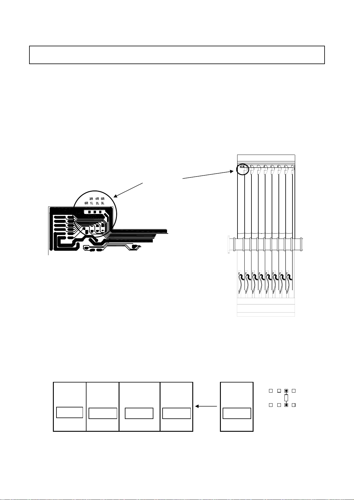
EXPANDER ASSIGNMENT
14. Depending on whether the expander is positioned on the left or right hand side of the main console, one or
more of the input connector circuit boards (AG2622) will have to be assigned to enable the channel mutes to
function correctly.
For consoles that have the expander on the right hand side of the console (e.g. expanded GL4000-824S and
GL4000-840S consoles) only the expander requires assignment.
For consoles that have the expander on the left hand side (e.g. expanded GL4000-832S consoles), all of the
input connector circuit boards will have to have the existing assignment links removed and re-assigned.
Refer to the assignment diagrams below.
The assignment links are 0R resistors
input connector circuit board. Fitting the links in various positions determines the assignment for each block
of 8 input channel mutes.
Trackside view
Input connector circuit board
Link assignments for each input connector circuit board
To avoid having to remove the input connector circuit board, fit the links onto the track side of the circuit board
‘Q’, located next to the 16 way ribbon harness connector on the
Location of
assignment
links
GL4000-824 + Expander
1 - 8
Allen & Heath AP2794 issue 3 7
9 - 16 Master Expander17 - 24
3R 4R 5R
6R 1L 2L 3L
Page 31

GL4000-832 + Expander
Note: remove existing assignment links on all connector circuit boards before re-assignment.
Expander
1 - 8
9 - 16 Master 25 - 32 17 - 24
3R 4R 5R
6R 1L 2L 3L
3R 4R 5R
6R 1L 2L 3L
3R 4R 5R
6R 1L 2L 3L
3R 4R 5R
6R 1L 2L 3L
3R 4R 5R
6R 1L 2L 3L
GL4000-840 + Expander
1 - 8
9 - 16
17 - 24 Master 33 - 40 25 - 32 Expander
3R 4R 5R
6R 1L 2L 3L
Attaching the base panels
15. Attach the base panel joining bracket ‘M’ to the console base using screws ‘E’. Refit the base panels onto
the expanded console using screws
‘E’ .
Console with integral meterbridge.
Fit the meterbridge side plate ‘R’ using the screws from the original side trim.
Allen & Heath AP2794 issue 3 8
Page 32

NUMBER STRIP POSITIONING
16. Carefully turn the console the correct way up and fit the new number strips. A complete set of number strips
‘L’ is supplied with the Expander kit. The diagrams below show the combination of strips to be fitted to the
expanded consoles.
GL4000-824 + Expander
1 - 8
GL4000-832 + Expander
Expander
1 - 8
9 - 16 Master Expander17 - 24
MONO
9 - 16 Master 25 - 32 17 - 24
GL4000-840 + Expander
1 - 8
9 - 16
17 - 24 Master 33 - 40 25 - 32
MONO
Expander
41 4442 43 45 46 4847
Allen & Heath AP2794 issue 3 9
Page 33

TESTING THE CONSOLE
17. The fitting of the expander module is now complete. Before re-plugging the console, apply power and check
for correct operation e.g. mutes & PFL LEDs illuminate.
Please note; to prevent damage to the console chassis, the expanded console must be supported along
its entire length.
Should you experience any difficulties in fitting this module or have any queries regarding your GL4000 console
please contact your ALLEN & HEATH agent. Include the console serial number in any correspondence.
Allen & Heath AP2794 issue 3 10
Page 34

ALLEN&HEA ALLEN&HEA
ALLEN&HEA
ALLEN&HEA ALLEN&HEA
THTH
TH
THTH
GL4000
MIXING CONSOLE
SYS-LINK
EXPANDER OPTION
This option connects a GL4000 console as a channel expander to a
second console with just one or two interconnecting cables.
Kit GL4000-SL1 = SINGLE
Single option to install SYS-LINK to one GL4000 console to allow
interconnection to a second console already fitted with SYS-LINK.
Kit GL4000-SL2 = DUAL (2x GL4000-SL1)
Dual option to install SYS-LINK to two GL4000 consoles.
Interconnecting cables not supplied.
For information on using SYS-LINK please refer to APPLICATIONS NOTE AP2787
FITTING INSTRUCTIONS
Publication AP2786
Issue 2 July 01
Page 35

FITTING THE GL4000 SYS-LINK EXPANDER OPTION
CHECK THE CONTENTS :
nn
n
nn
GL4000-SL1
rear extrusion earth wire
Ribbon harness assembly supplied
pre-formed and connected to circuit
board assembly.
Rear panel D type
chassis connector
fixings already fitted.
4 x foam strips
8 x AB2189
fig. 1
Contents:
1x SYS-LINK circuit board assembly with interconnecting harness and mountings already fitted.
1x SYS-LINK ribbon harness assembly with D type chassis connector fixings already fitted.
1x SYS-LINK Fitting Instructions (AP2786)
1x SYS-LINK Application notes (AP2787)
4x self adhesive foam pads (AK0332)
TOOLS REQUIRED :
oo
o
oo
LONG NOSE
1pt & 2pt CROSS POINT
2
GL4000 SYS-LINK OPTION
ALLEN & HEATH
Page 36

Only technically competent personel should attempt to fit the SYS-LINK option.
Disconnect the Power Supply Unit and cables from the console before fitting
the expander module.
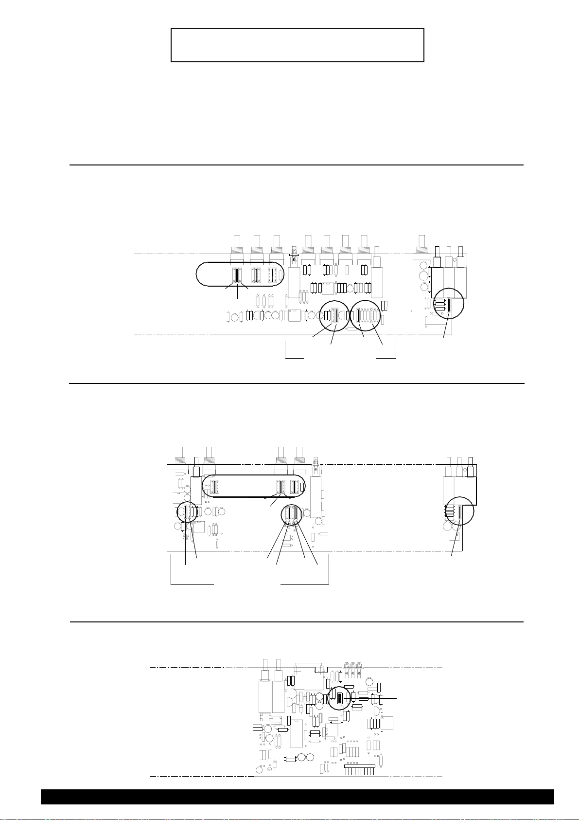
PRELIMINARY:
pp
p
pp
To fit the SYS-LINK option it is necessary to partially remove the INPUT CHANNEL circuit board assembly
next to the GROUP 1 circuit board to enable access to the SYS-LINK circuit board mounting holes. The
INPUT CONNECTOR circuit board assembly behind the SYS-LINK D type connector mounting holes on
the rear panel will also have to be removed. It is not necessary to remove any other circuit board assemblies
as access to the SYS-LINK connections can be made with a pair of long nose pliers.
REMOVE THE KNOB CAPS:
qq
q
qq
Pull off the knob caps and unscrew the nuts from the INPUT CHANNEL next to GROUP 1 channel. The
switch caps can remain in place.
Remove the optional Meterbridge if fitted.
REMOVE THE CONSOLE BASE :
rr
r
rr
Carefully invert the console and remove the base panel by removing all screws along the edges of the base
panel. Also remove the 3 screws in the centre of the largest panel
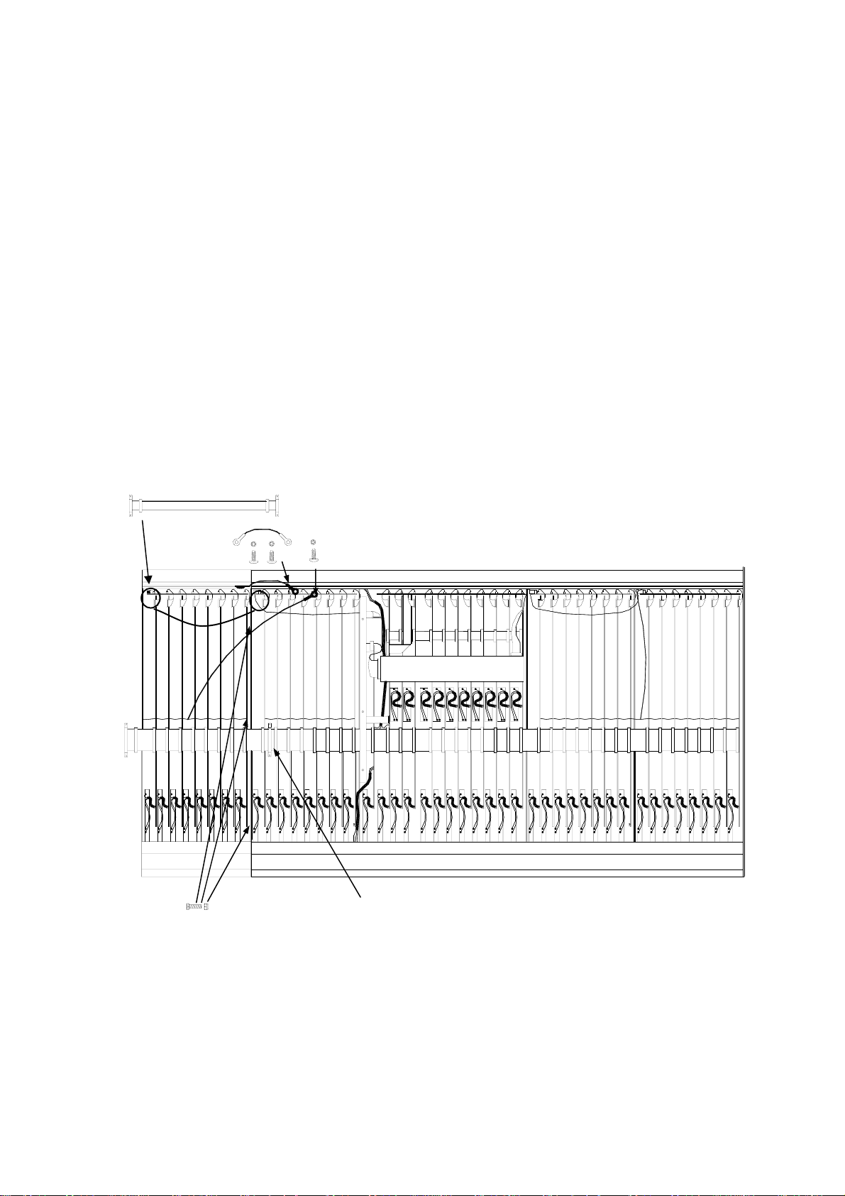
REMOVE THE INPUT CONNECTOR CIRCUIT BOARD ASSEMBLY:
ss
s
ss
The INPUT CONNECTOR circuit board assembly (A) directly behind the SYS-LINK connector mountings on
the rear panel must be removed to gain access to the SYS-LINK D type connector mounting holes.
Follow the procedure below:
1 Unscrew the 16 XLR mounting screws and remove the 32 jack socket nuts on the rear connector
panel.
2 Disconnect the 8 flexible flat cables (C) from the INPUT CHANNEL circuit board assemblies.
3 Disconnectd the ribbon harness (D)
4 Carefully remove the INPUT CONNECTOR circuit board assembly (A) and place to one side.
5 Now remove the SYS-LINK blanking plate.
C
Chan
24
D
B
A
Chan
1
ALLEN & HEATH
E
CONSOLE FRONT
GL4000-824 inverted with the base cover removed.
fig. 2
GL4000 SYS-LINK OPTION
3
Page 37

Refering to fig. 2, disconnect the MAIN HARNESS (E) plugged into the connectors mounted along the edge
tt
t
tt
of the circuit boards from INPUT CHANNEL 1 to GROUP 2.
The Input channel circuit board assembly next to GROUP 1 circuit board can now be removed and placed
uu
u
uu
on the adjacent Input channels. Take care not to stretch the fader wires that are still connected.
Remove the 8 screw fixings already partly screwed into the D type connectors on the SYS-LINK ribbon
vv
v
vv
harness assembly and place to one side.
Refering to fig. 3, fit the 4 self adhesive foam pads (F) in the positions indicated next to the front panel flange.
ww
w
ww
SYS-LINK HARNESS
INPUT CHANNEL
CIRCUIT BOARD
ASSEMBLY
F
CONSOLE FRONT
GL4000-824 inverted with the input connector circuit board assembly removed.
FITTING THE SYS-LINK RIBBON HARNESSES :
11
F
fig. 3
SYS-LINK
CIRCUIT
BOARD
F
F
Place the SYS-LINK circuit board assembly next to the GROUP 1 circuit board with the harness and ribbon
cables to the rear of the console. see fig. 3.
Slide the pre-formed SYS-LINK ribbon harnesses toward the back of the console and down the gap
between the Channel Input circuit boards and the back panel. Check the connectors are mounted into the
correct apertures on the rear panel.
Mount the 4 D type connectors using the 8 hex screws provided. see
4
GL4000 SYS-LINK OPTION
vv
v
vv
ALLEN & HEATH
Page 38

FITTING THE SYS-LINK HARNESS ASSEMBLY :
1 2
Refering to fig. 4, use a pair of long nosed pliers to fit the connectors onto GROUPS 1 - 8 and the LEFT
RIGHT and MONO circuit board assemblies in the following order:
GROUP 1 to GROUP 8, then LEFT, RIGHT and then finally the MONO circuit board assembly.
SYS-LINK ribbon harnesses
removed for clarity.
SYS-LINK CIRCUIT
BOARD ASSEMBLY
8x GROUP CIRCUIT BOARD ASSEMBLY
SYS-LINK WIRING HARNESS
LEFT CIRCUIT BOARD ASSEMBLY
RIGHT CIRCUIT BOARD ASSEMBLY
MONO CIRCUIT BOARD ASSEMBLY
ALLEN & HEATH
SYS-LINK harness circuit board interconnections
fig. 4
GL4000 SYS-LINK OPTION
5
Page 39

MOUNTING THE SYS-LINK CIRCUIT BOARD:
1 3
The SYS-LINK circuit board mounts onto the GROUP 1 circuit board using the 4 pillars already fitted to the
circuit board assembly. Two of the mounting pillars are fixed with screws (G) and two are 'snap-fit' (H).
H
G
G
H
fig. 5
To fit the SYS-LINK circuit board to the GROUP circuit board, unscrew the 2 screws already partly screwed
into the mounting pillars (G) and align all 4 pillars with the holes in the GROUP circuit board. Press the two
pillars (H) onto the GROUP circuit board assembly and fix the two pillars (G) with the screws provided.
Refit the INPUT CHANNEL circuit board assembly. Do not fit the channel nuts or knobs at this stage.
1 4
see
1 8
REFITTING THE INPUT CONNECTOR CIRCUIT BOARD ASSEMBLY
1 5
To refit the INPUT CONNECTOR circuit board into the console. Follow the procedure below refering to fig.
2:
1 Locate the circuit board assembly into the rear panel of the console.
2 Replace the 16 XLR mounting screws and the 32 jack socket nuts.
3 Reconnect the 8 flexible flat cables (C) into the sockets on the input channel circuit board assemblies
4 Plug on the ribbon harness (D).
Screw the SYS-LINK green earth wire onto the rear extrusion of the console with the screw and shakeproof
1 6
washer provided
1 7
Refering to fig. 2, re-fit the MAIN HARNESS (E) onto all circuit boards. Check the harnesses are correctly
aligned onto the circuit board connectors with pin 1 aligned with the red stripe of the ribbon harness.
1 8
REFITTING THE BASE :
Refit the base. Turn the console the correct way up and fit the pot nuts and knobs to the INPUT CHANNEL
replaced in
1 4
6
GL4000 SYS-LINK OPTION
ALLEN & HEATH
Page 40

1 9
PLUG ON THE INTERCONNECTING CABLES:
SYS-LINK connectors are female 25way D-type. Use 25way D-type male to male connector cables.
Connect pin one to pin one on all connectors. Connect shield (screen) to 0V. Standard cables are available
from electronic suppliers or computer shops. It is advised that the cable is a screened type less than 10
metres. Use professional quality locking connectors.
When connecting to equipment other than the GL Series link all unused audio inputs to 0V earth
at the SYS-LINK input.
2 0
TEST THE SYSTEM:
Test all SYS-LINK inputs and outputs for correct signal level and quality by probing the D-connector pins
or by interconnecting two consoles with SYS-LINK fitted. Test the PFL & AFL system for correct DC buss
switching.
The SYS-LINK circuit diagram and technical details are included for reference.
The SYS-LINK Applications Note AP2787 is included separately with these fitting instructions. Provide
this note to the user as applicable.
Please refer any queries to your Allen & Heath appointed service agent.
ALLEN & HEATH
GL4000 SYS-LINK OPTION
7
Page 41

ALLEN&HEA ALLEN&HEA
ALLEN&HEA
ALLEN&HEA ALLEN&HEA
THTH
TH
THTH
GL4000
MIXING CONSOLE
THE BENEFITS OF USING SYS-LINK
The GL4000 SYS-LINK option allows console to console interconnection by means of just one
or two cables. By connecting two GL4000 consoles together the number of input channels may
be increased. One console acts as a channel expander (slave) to the second (master). Up to 3
consoles may be 'daisy-chained' in this way. The system is also directly compatible with other
A&H consoles fitted with SYS-LINK.
Plugging consoles together using SYS-LINK connects the signals directly to the console busses
so avoiding the use of the main console outputs and channel inputs for the master / slave
connection. All the console channels are available to the user for input sources.
SYS-LINK CONNECTIONS
SYS-LINK connects all the console main busses including L, R, Mono, 8 Groups, 10 Aux sends,
and 4 matrices. The PFL & AFL systems are also interconnected such that operating PFL or
AFL on the slave console activates the master console monitor system. Operating PFL or AFL
on the master does not activate the slave monitor system which may be used for 'local'
monitoring if required. SYS-LINK connects the PFL & AFL audio mix and DC control buss.
SYS-LINK outputs are taken pre-fader so that the slave console output connectors may be used
for sub-mix or 'zone' feeds if required. All output signals are unbalanced, low impedance and
operate at a line level of -2dBu to prevent problems with audio interference and to maintain a
headroom of 23dB.
SYS-LINK inputs are unbalanced, operate line level at -2dBu and are high impedance to prevent
loading the connected source.
SYS-LINK is presented on two pairs of 25way female D-type connectors, one for the console
buss inputs and the other for the outputs. Several pins are provided for audio 0V earth.
USING SYS-LINK
Connect consoles using two standard 25way male to male D-type cables, available from
electronic suppliers or computer shops (25line male to male). It is advised that this cable is a
screened type if longer than 1 metre, no longer than 10 metres in total, and that professional
quality locking connectors are used. Connect all pins one to one with the screen to 0V.
Connect the slave console SYS-LINK output to the master console SYS-LINK input.
SYS-LINK may also be used to connect the GL4000 to other audio equipment. Make sure that
all unused inputs (except the PFL & AFL DC inputs) are linked to 0V earth at the SYS-LINK
input to prevent audible interference from connected audio signals. Connect line level signals
of around -2dBu. The GL4000 PFL & AFL systems may be activated by switching the PFL or
AFL DC inputs to 0V earth through a 15k ohm resistor.
For information on fitting SYS-LINK please refer to FITTING INSTRUCTIONS AP2786
SYS-LINK APPLICATIONS NOTE
Publication AP2787
Issue 2 July 01
Page 42

CONSOLE TO CONSOLE CONNECTION USING SYS-LINK
SYS-LINK connectors are 25way D-type female.
Use 25way D-type male to male connector cable.
Use screened cable, connect all pins.
0V0V0V0V0V0V0V
GRP5 out
GRP6 out
MONO out
AUX8 out
GRP7 out
GRP8 out
AUX7 out
AUX10 out
MTXB out
AUX9 out
MTXA out
OUT
Line level output at -2dBu
Unbalanced, in-phase
Low impedance <75 ohm
P/AFL DC output is open collector sink to 0V through 15k.
All outputs are pre-fader
MTXD out
0V
0V
MTXC out
B
0V0V0V0V0V0V0V
GRP5 in
GRP6 in
MONO in
AUX7 in
GRP7 in
GRP8 in
IN
AUX8 in
AUX10 in
MTXB in
AUX9 in
MTXA in
MTXD in
MTXC in
0V
0V
0V0V0V0V0V0V0V
LEFT out
GRP1 out
GRP2 out
RIGHT out
Line level input at -2dBu
Unbalanced, buffered in-phase
High impedance > 10k ohm
P/AFL DC input for pulldown to 0V through 15k resistor.
When connecting to equipment other than GL Series
link all unused audio inputs to 0V earth at the SYS-LINK
connector.
AUX2 out
AUX1 out
GRP3 out
GRP4 out
OUT
AUX4 out
AUX6 out
AFL out
PFL out
AUX3 out
AUX5 out
AFL DC
0V
0V0V0V0V0V0V0V
0V
LEFT in
PFL DC
A
GRP1 in
GRP2 in
RIGHT in
AUX1 in
GRP3 in
GRP4 in
IN
AUX2 in
AUX4 in
AUX6 in
AUX3 in
AUX5 in
AFL in
0V
PFL in
AFL DC
0V
PFL DC
IN B
MASTER GL4000
B to link GRP 5-8, AUX 7-10, MTX A-D
MASTER GL4000
IN A
IN A
B OUT
A OUT
SLAVE GL4000
A to link GRP 1-4, AUX 1-6, L, R, PFL & AFL
MULTI OUT
SLAVE GL2
2
GL4000 SYS-LINK APPLICATIONS NOTE AP2787 ALLEN & HEATH
Page 43

FITTING INSTRUCTIONS
METERBRIDGE FITTING INSTRUCTIONS
PFL/AFL ACTIVE
GL4000 meterbridge shown
The meterbridge has been designed to compliment the Allen & Heath GL series of Live consoles. Its purpose is to
monitor the programme signal at the console main outputs i.e; Groups 1 to 8, Left, Right and Mono. The meterbridge
is available in various sizes to fit each console size and runs full length.
Connecting the meterbridge to a console is very easy and only requires plugging in the meterbridge harness and
tightening the three "grub" screws in the lower lip of the meterbridge.
To fit the meterbridge:
1.) Carefully unpack the meterbridge and
fit it over the console rear extrusion (A)
as shown in fig 1. Make sure all of the
grub screws (B) are fully withdrawn
from the meterpod extrusion (C) before
fitting.
2.) Once the meterbridge is in place, tighten
the grub screws (B) to secure the
meterbridge in place.
3.) Plug in the meterbridge harness (D) into
the connector marked METERPOD
on the rear panel of the console. See fig.
2.
A
C
B
FIG. 1
D
FIG. 2
Please note; the PFL LED indicator illuminates when any PFL is selected with the PFL signal level displayed on
the MONO meter.
Manufactured in the UK by:
Allen & Heath Limited
Kernick Industrial Estate,
Penryn,
Cornwall. TR10 9LU.
tel: 44 (0) 870 755 6250
Publication AP2126 Issue 4
copyright © 2001 ALLEN & HEATH. All
rights reserved.
L3dSM
fax: 44 (0) 870 755 6251
http://www.allen-heath.com
Section A - 1
ALLEN & HEATH
Page 44

SECTION C
TECHNICAL
DIAGRAMS
CAUTION !
C
TO AVOID DAMAGE TO INTERNAL COMPONENTS BY
MISHANDLING AND/OR MISCONNECTION, ONLY
TECHNICALLY COMPETENT PERSONNEL SHOULD
ATTEMPT SERVICE WORK ON THIS CONSOLE.
L4DSM2
Section C - 1
ALLEN & HEATH
Page 45

Attention Service Departments
TECHNICAL BULLETIN
Ref.: AHTB96010 Issue No 1 Date 16/01/97 Page 1of: 1
Title: New fader specified for GL4000 Authorisation: CD
The following information applies to all GL4000 consoles after serial number 401300.
Origin of the change:
In accordance with Allen & Heath’s policy of continual product development, a new fader has been specified for
GL4000 consoles. The fader offers a custom taper that has been designed to match the needs of engineers using
the consoles in today’s live environment.
Details:
GL4000’s with serial numbers which precede the cut-off number stated above have been fitted with Jung Poon
faders. The order codes for these are:
AI2665 - Mono Fader
AI2664 - Stereo Fader
GL4000’s from Serial No 401300 onwards will be fitted with the Alps K-fader which has a special taper. The
numbers for these are as follows:
AI8109 - Mono Fader
AI8110 - Stereo Fader
Note that since the tapers of the two faders are different, it will be necessary to check that the correct fader is
ordered whenever replacements are needed. Otherwise, the channel gain will not correspond to the fader panel
silk-screen.
Please note however that the audio performance of the console will not be compromised by inadvertently fitting the
‘wrong’ fader type. The channel will perform equally well with either fader type.
ALLEN & HEATH
Section C - 2
L4DSM2
Page 46

FRONT PANEL LAYOUT
L4DSM2
Section C - 3
ALLEN & HEATH
Page 47

REAR PANEL LAYOUT
INPUT SECTION
MASTER SECTION
STEREO
INPUT SECTION
MONO
Page 48

SHEET 1 OF 3
MONO / STEREO INPUT & TALKBACK
Page 49

GROUP / AUX / MATRIX / LR / MONO / 2 TRACK
SHEET 2 OF 3
Page 50

MUTE AUTOMATION
SHEET 3 OF 3
Page 51

GL4000-824 INTERNAL LAYOUT
Console inverted with the base removed.
(x1)
HARNESS
1
8
16 WAY LEFT HAND
(x1)
INPUT CONNECTOR PCB
(x1)
HARNESS
16 WAY MASTER
(x1)
(x1)
SLAVE PCB
9
(x8)
INPUT PCB
16
(x8)
GROUP PCB
}
(x2)
L / R PCB
(x1)
MASTER CONNECTOR PCB
(x1)
HARNESS
16 WAY METER
(x1)
MICRO PCB
(x1)
16 WAY RIGHT
HAND HARNESS
(x1)
HARNESS
26 WAY MPU
(x4)
STEREO PCB
MONO PCB
17
(x1)
MASTER PCB
24
(x1)
HARNESS
40 WAY MAIN
Page 52

CHASSIS EARTH TERMINAL
2BA SOLDER TAG (AK0001)
M5 CRINKLE WASHER (AB0304)
TO MONO PCB (AG2625)
Bk
Bl
Gn
Rd
P2
P4
P5
P3
TO MASTER PCB
(AG2626)
Gn 24/0.2
P2
TO LITTLITE XLR'S
Refer to LITTLITE
wiring diagram
CHASSIS
EARTH
TERMINAL
TO MPU PCB (AG2624)
Red
Gn
P22GnP20
P21
CONSOLE
POWER
WIRING
TO MONO PCB
GN 24/0.2
TO MASTER CONN
PCB (AG2627)
2x GN 32/0.2
P3
GN 24/0.2
CABLE TIE TO
MASTER CONNECTOR PCB
(AK0151)
RED 24/0.2
BK 24/0.2
BL 16/0.2
P2
GN 24/0.2
GY 16/0.2
BN 16/0.2
GN 32/0.2GN 24/0.2 GN 2 4/0.2 GN 24/0.2
DC POWER CONNECTOR
Pin 1 = +16V (RED)
Pin 3 = -16V (BLACK)
Pin 4 = CHASSIS 0V (GREEN/YELLOW)
Pin 5 = AUDIO 0V (GREEN)
Pin 10 = +48V (BLUE)
Pins 2, 6, 7, 8, 9 = not connected
RED 16/0.2
CHASSIS
EARTH BAR
TO POWER SKT
Bn
Gy
Gn
Pin 3
Pin 4
Pin 1
Refer to console power
wiring drawing
LITTLITE 4 PIN XLR WIRING
22R 2.5W
3
4
XLR
BN 16/0.2GN 16/0.2
SLEEVING
2
TC LINK
1
2 x 4 PIN XLR
(AL8104)
VIEW FROM BEHIND FRONT PANEL (CONSOLE UPSIDE DOWN)
VIEW FROM BEHIND FRONT PANEL (MIXER UPSIDE DOWN)
GN 16/0.2
3
4
XLR
GY 16/0.2
SLEEVING
22R 2.5W
2
1
TC LINK
Page 53

Page 54

Page 55

Page 56

Page 57

Page 58

Page 59

Page 60

Page 61

Page 62

Page 63

Page 64

Page 65

Page 66

Page 67

Page 68

Page 69

Page 70

Page 71

Page 72

Page 73

Page 74

Page 75

Page 76

Page 77

Page 78

Page 79

Page 80

Page 81

Page 82

Page 83

Page 84

Page 85

Page 86

Page 87

Page 88

Page 89

+V
JP2
LINK OPT
JP3
LINK OPT
-V
R11
e
C10
10/16
R10
47K
GRP1/7
100K
D10
1N4148
U1A
TL072
2
3
1
D11
1N4148
V_DIV_REFA
R12
1K0
3
2
R13
47K
U2A
LM393
1 3
VR1
PR VA 10K
C11
10/16
1
2
M1B
PEAK
1
+VA
METER VU
2
R14
1K8
M1A
METER VU
3 4
GRP4/L
C40
10/16
U4B
V_DIV_REFA
R41
100K
D40
1N4148
R40
47K
U3B
TL072
6
5
D41
7
1N4148
5
6
R42
1K0
R43
47K
LM393
2
1 3
VR4
PR VA 10K
C41
10/16
7
M4B
PEAK
1
+VA
METER VU
2
R44
1K8
M4A
METER VU
3 4
M7B
PEAK
+VA
METER VU
M7A
METER VU
3 4
1
2
R45
47R
*
U2B
V_DIV_REFA
d
R21
100K
D20
1N4148
GRP2/8
C20
10/16
R20
47K
U1B
TL072
6
5
D21
7
1N4148
c
5
6
R22
1K0
R23
47K
LM393
1 3
VR2
PR VA 10K
C21
10/16
7
2
M2B
PEAK
1
+VA
METER VU
2
BLGND
R24
1K8
M2A
METER VU
3 4
U6A
V_DIV_REFA
R51
100K
D50
1N4148
C50
10/16
R50
47K
R25
47R
GRP5/R
U5A
TL072
2
3
D51
1
1N4148
3
2
R52
1K0
R53
47K
LM393
2
1 3
VR5
PR VA 10K
C51
10/16
1
M5B
PEAK
1
+VA
METER VU
2
R54
1K8
M5A
METER VU
3 4
M8B
PEAK
+VA
METER VU
M8A
METER VU
3 4
1
2
BLGND
b
C30
R30
GRP3
PAFL_DC
a
*
10/16
R35 100K
ISSUE BY DATE
A AAT 19-07-01
1 AAT 14-08-01
ABCDE FGH
+VA
R38
*
2K2 1%
U3A
*
47K
2
3
*
R37
R36
**
47K
2M2
R31
100K
1N4148
TL072
FILE:
*
D30
*
1
+VA
LD1
C4535_1P2.Sch
V_DIV_REFA
D31
R32
**
1K0
1N4148
*
LED T1 3MM RED
3
2
R33
*
47K
U4A
LM393
1 3
VR3
PR VA 10K
C31
*
10/16
M3B
R34
1
*
1K8
M3A
METER VU
3 4
2
1
*
*
PEAK
METER VU
2
+VA
JP4
LINK OPT
*
PRINTED:
U6B
V_DIV_REFA
R61
100K
D60
1N4148
C60
10/16
R60
47K
GRP6/MON
13:53:33 3-Oct-2001 A3
U5B
TL072
6
5
D61
7
1N4148
GL SERIES METERS
TITLE:
METERS AND DRIVERS
PAGE:
DRG No: ISSUE: SHEET: OF
C4535 2 3
5
6
R62
1K0
R63
47K
LM393
2
1 3
VR6
PR VA 10K
C61
10/16
7
1
M6B
PEAK
1
+VA
METER VU
2
R64
1K8
M6A
METER VU
3 4
M9B
PEAK
+VA
METER VU
M9A
METER VU
3 4
1
2
R65
47R
BLGND
ALLEN&HEATH
Kernick Industrial Estate,
Penryn, Cornwall,
England. TR10 9LU
Tel:
+44 (0)8707 556250
Fax:
+44 (0)8707 556251
Page 90

+VA
V+
V-
TL072
U2C
R1
10R PF
R2
10R PF
8
4
8
e
d
U1C
4
-VA
+V +VA
-V
V+
V-
LM393
U3C
8
4
D1
1N4002
D2
1N4002
V+
V-
TL072
BLGND
U4C
JP1
LINK OPT
8
4
V+
V-
LM393
C1
47/25
C2
47/25
U5C
8
4
V+
V-
TL072
-VA
-VA
U6C
R5
RES NF
8
4
V+
V-
LM393
+VA
R3
10K
V_DIV_REFA
R4
5K6
LK1
LINK TCW
LK2
LINK TCW
LK3
LINK TCW
LK4
LINK TCW
LK5
LINK TCW
AI1
HOLE-AI
AI2
HOLE-AI
LK6
LINK TCW
LK7
LINK TCW
LK8
LINK TCW
LK9
LINK TCW
LK10
LINK TCW
LK11
LINK TCW
LK12
LINK TCW
LK13
LINK TCW
LK14
LINK TCW
LK15
LINK TCW
FH1
HOLE-FIXING 3.5MM
FH2
HOLE-FIXING 3.5MM
FH3
HOLE-FIXING 3.5MM
LK16
LINK TCW
LK17
LINK TCW
LK18
LINK TCW
LK19
LINK TCW
LK20
LINK TCW
LK21
LINK TCW
LK22
LINK TCW
LK23
LINK TCW
LK24
LINK TCW
LK25
LINK TCW
LK26
LINK TCW
LK27
LINK TCW
LK28
LINK TCW
LK29
LINK TCW
LK30
LINK TCW
c
-V -V
GRP1/7
GRP6/MON
GRP5/R
b
a
ISSUE BY DATE
A AAT 19-07-01
1 AAT 14-08-01
ABCDE FGH
CN1
**
16
14
12
10
8
6
4
2
15
16
15
13
14
13
11
12
11
9
9
10
7
7
8
5
5
6
334
112
BOX 8X2 M 90 DEG
C4535_1P3.Sch
FILE:
+V +V
PAFL_DC
GRP2/8
GRP4/L
GRP1/7
GRP3
GRP5/R
CN2
112
334
5
5
7
7
9
9
11
11
13
13
15
15
BOX 8X2 M 90 DEG
2
4
6
6
8
8
10
12
14
16
GRP2/8
10
GRP4/L
12
GRP6/MON
14
16
PRINTED:
GL SERIES METERS
TITLE:
POWER AND CONNECTORS
PAGE:
14:10:13 3-Oct-2001 A3
DRG No: ISSUE: SHEET: OF
C4535 3 3
1
ALLEN&HEATH
Kernick Industrial Estate,
Penryn, Cornwall,
England. TR10 9LU
Tel:
+44 (0)8707 556250
Fax:
+44 (0)8707 556251
Page 91

Page 92

Page 93

Page 94

Page 95

Page 96

SECTION D
POWER SUPPLY
CAUTION !
D
TO AVOID DAMAGE TO INTERNAL COMPONENTS BY
MISHANDLING AND/OR MISCONNECTION, ONLY
TECHNICALLY COMPETENT PERSONNEL SHOULD
ATTEMPT SERVICE WORK ON THIS UNIT.
L4DSM2
Section D - 1
ALLEN & HEATH
Page 97

TECHNICAL DESCRIPTION
The ALLEN & HEATH RPS11 power supply is purpose designed for the GL4000 range of sound reinforcement
consoles.
CONSTRUCTION
All metal chassis for rack mounting in a 19" by 3U space. The unit comprises of a 16swg steel front panel with integral
top cover and a separate 16swg steel chassis base on which all the main components are mounted.
INSTALLATION
The RPS11 is designed to occupy 3U (5.25 inches) of rack space. An important consideration when rack mounting the
unit is the need for natural convection of air flow over the whole unit. Good ventilation below the unit, in the floor or
back of the rack, will ensure a path for continuous air flow. Other equipment in the rack which is known not to produce
a significant amount of heat should be mounted below the unit. Equipment which also relies on good air flow within
the rack (i.e. most power amplifiers and other power supplies) should be given due consideration and some space should
be provided between such units and between the RPS11 unit. Forced convection, by means of a fan-tray, may be
desirable in this situation.
The RPS11 can be operated as a free standing unit without requiring any special cooling arrangement, but should not
be covered in any way. Always stand the unit on a firm flat surface well away from any soft furnishings.
THE POWER SUPPLY AND CONSOLE EARTHING
The RPS11 is a linear power supply which, like other linear supplies, produces DC voltages by rectifying, smoothing
and regulating AC voltages from the secondary windings of a mains transformer. This unit connects to the local AC mains
supply and provides the regulated DC operating voltages required by the GL4000 console. The RPS11 DC output lead
is terminated at both ends with an inline 10 pin round connector. A male connector at one end and a female connector
which plugs into the console DC INPUT at the other. Near to the console DC INPUT connector is an earth terminal
labelled CHASSIS GROUND. This terminal is connected to mains earth via the DC power cable of the RPS11.
THE CHASSIS METALWORK IS ALWAYS CONNECTED TO MAINS EARTH VIA THE EARTH WIRE IN
THE MAINS PLUG. DO NOT REMOVE THE EARTH WIRE CONNECTION IN THE MAINS PLUG !
SPECIFICATION
AC MAINS INPUT VOLTAGE RANGES: 100V - 120V, 220V - 240V @ 47Hz to 63Hz single phase
POWER CONSUMPTION: 320VA 300W
DC OUTPUTS: +16V @ 5A, -16V @ 5A, +48V @ 200mA
OUTPUT NOISE & RIPPLE: < 1mV (peak to peak)
DC Output Socket Pin Connections
Pin 1 = +16 Volts
Pin 3 = -16 Volts
Pin 4 = CHASSIS 0V
Pin 5 = AUDIO 0V
Pin 10 = +48 Volts
Pins 2, 6, 7, 8, 9, = not connected
Overall Dimensions
Front Panel Chassis (Maximum External)
19 inch 3U (482mm x 133mm) Height: 135mm including feet (5.31 inches)
Weight : 9.5Kg (21 pounds)
ALLEN & HEATH
Section D - 2
Width: 419mm (16.50 inches)
Depth: 235mm (9.25 inches)
L4DSM2
Page 98

FUSE RATING & REPLACEMENT
The AC mains fuse is located on the rear of the RPS11 unit next to the AC mains connector. In the event of a mains surge
or under-rated fuse value, the mains input fuse will rupture. Switch the unit mains “on/off ” switch to the off position
and remove the mains lead plug from the “AC MAINS IN” socket on the rear of the unit. Lever out the fuseholder square
top with a suitable tool and pull the fuse carrier assembly clear of the body. Replace the fuse and push the fuse carrier
back into place.Check that the AC mains input voltage setting is correct for the mains supply in your area before
switching the unit on again.
Check the correct fuse is fitted for the selected mains input voltage.
Voltage Setting Fuse
220/230 VAC T 3.15A / 250V 20mm
100/120 VAC T 5.0A / 250V 20mm
MAINS VOLTAGE SETTING
The RPS11 is capable of operating over a wide range of AC mains input voltages by means of a comprehensive set of
selectable voltage settings. It is important to check that the RPS11 has the correct voltage setting as marked on the rear
panel of the power supply. Confirm that the voltage setting matches the local AC mains supply in your area.
Check the arrow indicates the correct AC mains
voltage setting for your local AC mains supply
AC MAINS IN ~
FUSE TYPE AC SUPPLY
T 3.15A 20mm 220 - 240V~
T 5.0A 20mm 100 - 120V~
Set:
100 V marking for ac mains input 100-115 V ac
120 V marking for ac mains input 115-125 V ac
220 V marking for ac mains input 210-230 V ac
47-63Hz
320VA MAX
300W MAX
To alter the AC mains input voltage setting,
lever out the fuseholder square top with a
suitable tool. Pull the fuse carrier assembly
clear of the body, rotate the fuse carrier
body until the required voltage aligns with
the arrow and push the fuse carrier back
into place.
Check the correct fuse is fitted for the
selected mains input voltage.
L4DSM2
230 V marking for ac mains input 230-264 V ac
DO NOT ATTEMPT TO USE THE POWER SUPPLY IF IT IS SET TO A DIFFERENT
AC MAINS INPUT VOLTAGE TO THE LOCAL AC MAINS SUPPLY IN YOUR AREA
Section D - 3
ALLEN & HEATH
 Loading...