

Page 1
ALLEN&HEATH
GL3300
8GD OPTION
The 8GD option enables access to all 8 group outputs from a single
25 way D type connector.
Please note, the 8GD option cannot be installed if the SYS-LINK
option is already installed.
Kit Part No: GL3300-8GD
Single option to install 8GD to one GL3300 console.
Interconnecting cables not supplied.
FITTING INSTRUCTIONS
Publication AP3222
Issue 2 July 2001
Page 2
FITTING THE 8GD OPTION
The 8GD option is supplied as a pre-tested assembly to be installed in the Allen & Heath GL3300 console. It
enables access to all 8 group outputs on impedance balanced pins of a female 25 way D type connector.
Access is required to the console internal assemblies with soldering of harness wiring.
THIS WORK SHOULD ONLY BE CARRIED OUT BY TECHNICALLY COMPETENT PERSONNEL.
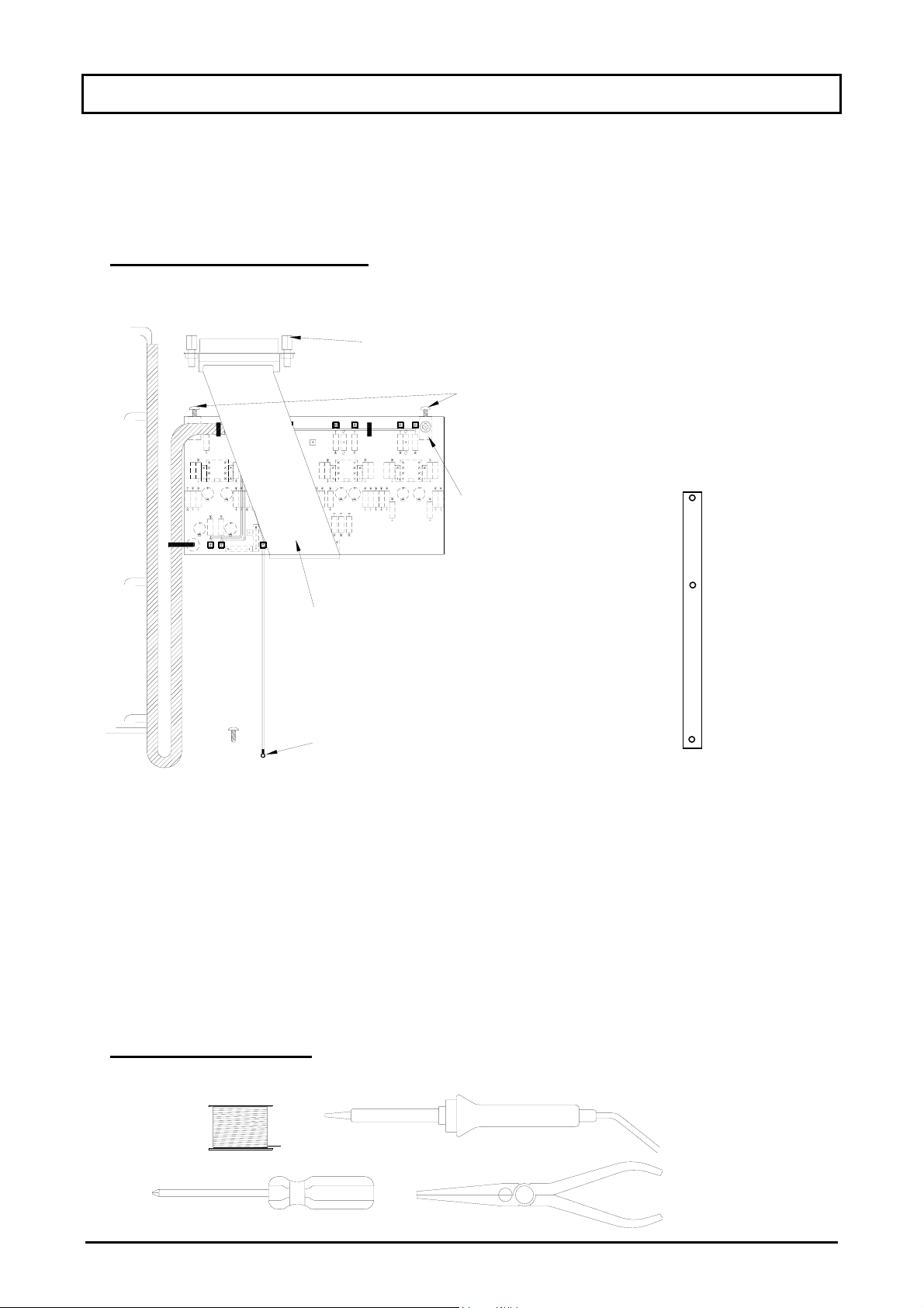
1. CHECK THE CONTENTS:
Please check the circuit board assembly and associated components are supplied with the kit.
2x D type connector fixing already fitted
2x fixing screws
already fitted
2x Mounting block
Ribbon harness with 25 way
D type connector fitted
Green wire with solder tag
and fixing screw
Blanking plate
fig. 1
Contents:
1x 8GD circuit board assembly with interconnecting harness and mountings already fitted.
1x 8GD ribbon harness with D type connector fixings already fitted.
1x blanking plate
1x 6AB screw
1x 8GD Fitting instructions (AP3222)
2. TOOLS REQUIRED:
2
SOLDER SOLDERING IRON
with small tip
1pt CROSS POINT LONG NOSE
GL3300 8GD OPTION
Page 3

3. REMOVE THE CONSOLE BASE
Before installing the option, remove all power to the console and disconnect any signal cables where
necessary. Ensure you have a good work surface and clear area before starting work. Invert the console and
remove the base.
fig.2
4. REMOVE SYS-LINK BLANKING PLATE
Working from the rear of the console locate the SYS-LINK blanking plate and remove it. Keep the fixing
screws as they will be required later
To remove the blanking plate,
remove the 3 fixing screws.
fig.3
5. CHECKING THE NOMINAL OPERATING OUTPUT LEVEL.
The outputs are impedance balanced with a factory set nominal operating level of +4dBu. The operating
levels can be changed to –10dBV by moving the jumper selector links from HI to LO.
LO= -10dBV
fig.3
fig.4
GL3300 8GD OPTION
HI= +4dBu
3
Page 4

6. LOCATE MONO INPUT CONNECTOR CIRCUIT BOARD ASSEMBLY
The 8GD circuit board assembly mounts onto the mono input connector circuit board assembly to the left of
the master section.
8GD circuit board assembly mounts onto the
mono input connector circuit board assembly
Console inverted with the base removed.
fig.5
7. MOUNTING THE 8GD CIRCUIT BOARD ASSEMBLY
Remove the 2 fixing screws as indicated in fig. 1 from each of the mounting blocks on the 8GD circuit board
assembly.
When mounting the 8GD circuit board assembly, ensure that the track side is facing upwards.
Locate the 2 mounting holes on the mono input connector circuit board assembly and align the mounting
block holes on the 8GD circuit board assembly. Screw the two assemblies together.
2x fixing screws
4
fig.6
GL3300 8GD OPTION
Page 5

8. SOLDERING THE 8GD WIRING HARNESS
)
)
y
Connect the harness wires to the appropriate pads on the Group circuit board assemblies. (see figure 7).
8GD circuit board assembl
M14
Green
Group 1
Group 2
8GD wiring harness
Bn
Or (M9)
Rd (M8)
Y (M8
Trackside view of Group
circuit board wiring pads
W (M14)
Bk (M13)
Group 3
Gn (M9)
Blu (M8
Group 4
Vio (M9)
Gy (M8)
GL3300 8GD OPTION
fig.7
5
Page 6

9. FITTING THE ‘D’ TYPE CONNECTOR
Form the ribbon harness over the 8GD circuit board assembly and mount the 25 way ‘D’ type connector in
the SYS-LINK OUT ‘B’ position. Fix the green wire with the solder tag to the extrusion using the screw
provided (see figure 8).
Green wire
& solder tag
Ribbon harness with
D-type connector
fig.8
10. FITTING THE NEW BLANKING PLATE
Fit new blanking plate over the remaining SYS-LINK positions using the screws from the original blanking
plate.
11. REPLACE CONSOLE BASE
Refit the console base (refer to figure 2) and replace fixing screws. Turn the console the correct way up.
12. CONSOLE AND 8GD OPERATION
Test the console and check all functions work correctly in particular the 8GD option outputs. The outputs are
impedance balanced using 47R resistors. To connect the option outputs to unbalanced inputs, connect the
cold (-ve) pins to ground (0V).
6
13
25
GROUPS OUTPUTS
1 2 3 4 5 6 7 8
^^^^^^^^
GCH GCH GCH GCH GCH GCH GCH GCH
25way female
GL3300 8GD OPTION
1
14
H = HOT (+VE)
C = COLD (-VE)
G = GROUND (0V)
 Loading...