

Page 1

Page 2
LIMITED ONE YEAR WARRANTY
This product has been manufactured in the UK by ALLEN & HEATH and is warranted
to be free from defects in materials or workmanship for a period of one year from the
date of purchase by the original owner.
To ensure the high level of performance and reliability for which this equipment has
been designed and manufactured please read this User Guide before use.
In the event of a failure notify and return the defective unit to ALLEN & HEATH or
its authorised agent as soon as possible for repair under warranty subject to the
following conditions:
CONDITIONS OF WARRANTY:
1. The equipment has been installed and operated in accordance with the instructions in the User
Guide.
2. The equipment has not been subject to misuse either intended or accidental, neglect, or alteration
other than as described in the User Guide or Service Manual, or approved by ALLEN & HEATH.
3. Any necessary adjustment, alteration, or repair has been made by ALLEN & HEATH or its
authorised agent.
4. The defective unit is to be returned carriage prepaid to ALLEN & HEATH or its authorised agent
with proof of purchase.
5. Units to be returned should be packed to avoid transit damage.
These terms of warranty apply to UK sales. In other territories the terms may vary according to legal
requirements.
This product complies with the European Electromagnetic
Compatibility Directives 89/336/EEC & 92/31/EEC and
the European Low Voltage Directives 73/23/EEC & 93/68/
EEC.
ALLEN & HEATH AGENT:
U.K. FACTORY:
ALLEN & HEATH.
Kernick Industrial Estate,
Penryn.
Cornwall. TR10 9LU.
A DIVISION OF HARMAN INTERNATIONAL INDUSTRIES Ltd.
copyright © 1997 ALLEN & HEATH. All rights reserved Publication..............AP2548 Issue 2
Page 3

3
INTRODUCTION
The GL2000 continues ALLEN & HEATH’s commitment to provide high quality audio mixing consoles
engineered to meet the exacting requirements of today’s audio business. It brings you the latest in high performance
technology and offers the reassurance of over two decades of console manufacture and customer support.
This user guide presents a quick reference to the function, application and installation of the GL2000. For further
information on the basic principles of audio system engineering please refer to one of the specialist publications
available from bookshops and audio equipment dealers.
Whilst we believe the information in this guide to be reliable we do not assume responsibility for any inaccuracies.
We also reserve the right to make changes in the interest of further product development.
SERVICE AND TECHNICAL SUPPORT
Under normal conditions the GL2000 does not require user maintenance or internal calibration. Any service work
required should be carried out by qualified service personnel only.
We are able to offer further product support through our worldwide network of approved dealers and service agents.
To help us provide the most efficient service please keep a record of the console serial number, and date and place
of purchase to be quoted in any communication regarding this product.
F
SAFETY WARNING !
Mains electricity is dangerous and can kill. Mains voltage is present within
the GL2000. Do not carry out any work within the console while it is powered.
The console mains voltage setting is indicated on the rear of the console.
Check your mains wiring and earthing before switching on.
DO NOT REMOVE THE MAINS EARTH CONNECTION!
The console chassis is connected to mains earth to ensure your safety.
Audio 0V connects to the console chassis internally. Should problems be
encountered with ground loops, operate the audio ground lift switches on
connected equipment or disconnect the cable screens at one end. Refer to
the section on 'EARTHING' in this User Guide.
PRECAUTIONS.
l AC POWER: Check the power unit for correct AC mains voltage setting before switching on. Allow
adequate space around the unit for ventilation.
l CONNECTIONS: Use audio connectors and cables only for their intended purpose. Do not connect any
source of AC or DC power to the console audio connectors. Do not connect the output
of power amplifiers directly to the console.
l CLEANING: Avoid the use of chemicals, abrasives and solvents. The control panel is best cleaned
with a soft brush and lint-free cloth. To remove stubborn marks (such as chinagraph
pencil) isopropyl alcohol may be used.
l LUBRICATION: The faders, switches and potentiometers are lubricated for life. The use of electrical
lubricants on these parts is not recommended.
l DIRT, DUST, SMOKE and MOISTURE: Prevent damage to the moving parts, such as faders and
potentiometers, and cosmetics by avoiding drinks spillage, tobacco ash and smoke,
and exposure to rain and condensation. Protect from excessive dirt, dust, heat and
vibration.
Page 4
CONNECTING AC MAINS TO THE CONSOLE
Refer to the SAFETY WARNING on the first page of this User Guide.
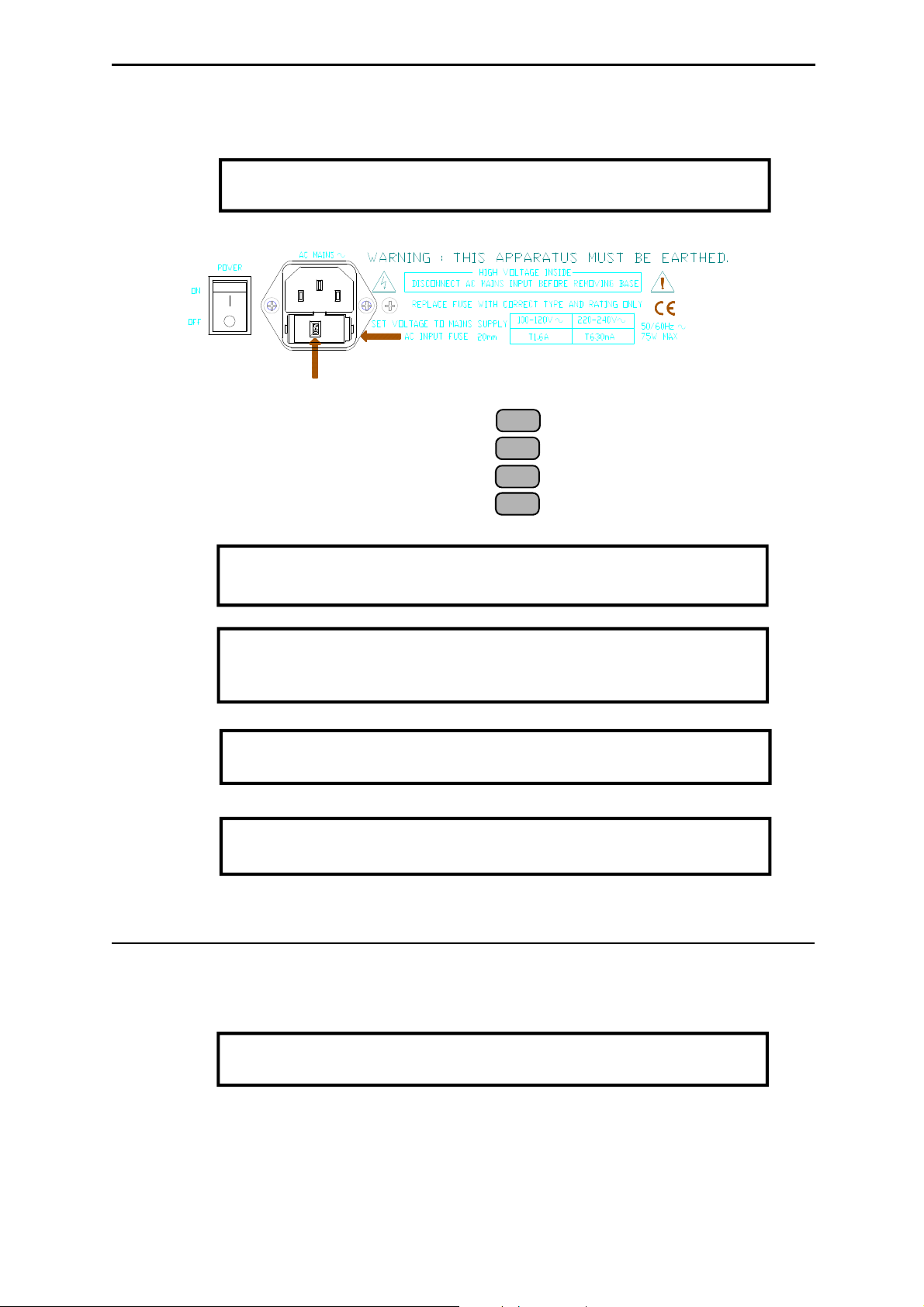
Mains input to the GL2000 is via a standard 3 pin IEC mains input connector. A mains cable with moulded mains
plug suitable for the local supply is supplied.
Check that the voltage indicated in the fuseholder window is the same
F
as the mains supply in your area.
AC mains supply = 100 to 110 V.AC 100 T 1.6A 20mm fuse
AC mains supply = 110 to 125 V.AC 120 T 1.6A 20mm fuse
AC mains supply = 210 to 230 V.AC 230 T 630mA 20mm fuse
AC mains supply = 235 to 260 V.AC 240 T 630mA 20mm fuse
To avoid the risk of fire replace the fuse only with the correct type and
F
F
F
F
EARTHING THE AUDIO SYSTEM
value as specified on the unit.
It is normal for the power unit to dissipate heat. Ensure adequate
ventilation around the unit. Do not cover the unit or position it on soft
furnishings during operation.
Always switch the unit off before connecting or disconnecting the
console power cable.
This unit contains no user serviceable parts. Do not remove the
cover. Refer servicing to qualified service personnel only.
The console chassis is connected to mains earth via the power cable. Audio 0V is connected internally to the chassis
and therefore mains earth. In this way all signal returns and connector shields are connected to mains earth at the
console.
To ensure operator safety do not remove the earth connection from
F
For best performance it is important that the earth system is solid, clean and noise-free. To prevent mains born
and external interference pickup from lighting equipment, motors and other mains powered equipment it is
recommended that a separate 'clean' mains distribution outlet is used for the audio system.
All signal cables should have their screens connected to earth at the connector. If earth (ground) loop problems
result in audible hum or buzz then disconnect the cable screen connection at one end, usually the destination end.
This may be done within the cable plug or by operating the 'ground lift' switch if available on the connected
equipment. Many DI boxes and power amplifiers include this facility.
the AC mains plug.
Page 5
5
PLUGGING UP THE CABLES
Where possible use balanced connections to prevent noise and interference pickup especially on long microphone
cable runs. Avoid running audio cables next to AC mains, computer or lighting cables, near thyristor dimmer units
or power supplies etc. The use of low impedance sources such as good quality microphones of 200 ohms or less
significantly reduces interference pickup. Many problems can be avoided by taking time to check that all cables
are correctly wired (in-phase) with professional quality cable and carefully soldered connections. The following
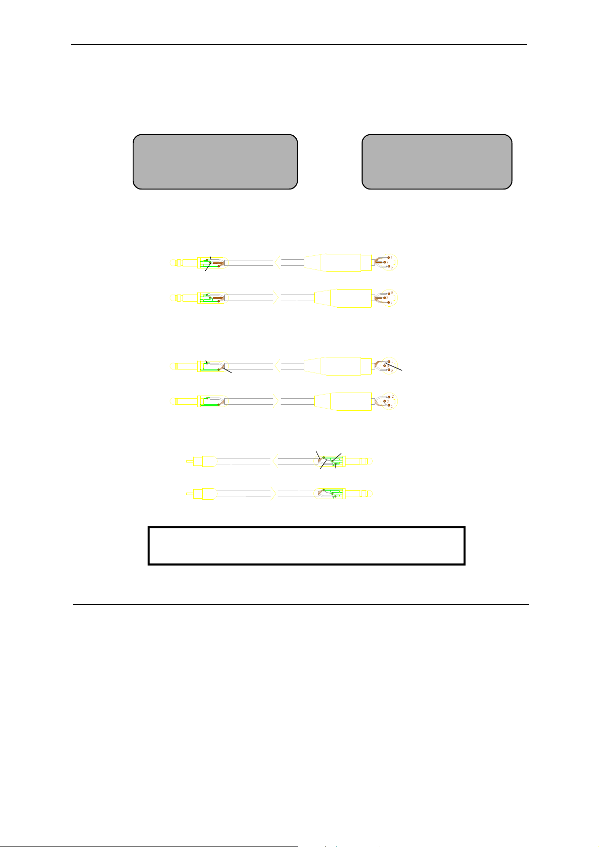
wiring convention is used:
XLR pin 1 = 0V earth shield 1/4" jack tip = + / hot / signal / left / send
pin 2 = + / hot (in phase signal) ring = - / cold / 0V / right / return
pin 3 = - / cold (out of phase signal) sleeve = 0V earth shield
To connect an unbalanced source to a balanced console input, link the cold input (XLR pin 3 or jack ring) to 0V
earth (pin 1 or jack sleeve) at the console. To connect a balanced console output to an unbalanced destination link
the cold output to 0V earth at the console.
Tip
OUTPUT
3-PIN XLR FEMALE PLUG
INPUT
3-PIN XLR MALE PLUG
CONSOLE
CONNECTIONS
BALANCED
Sleeve
Ring
Tip
Ring
¼" 3-POLE (STEREO) JACK PLUG
TWIN SCREENED CABLE
Screen not connected at destination
Tip
OUTPUT
3-PIN XLR FEMALE PLUG
INPUT
3-PIN XLR MALE PLUG
Sleeve
Ring
OUTPUT
Tip
link
¼" 3-POLE (STEREO) JACK PLUG
Ring
Sleeve
Tip
INPUT
link
CONSOLE
CONNECTIONS
CONSOLE
CONNECTIONS
UNBALANCED
UNBALANCED
Sleeve
Tip
¼" 2-POLE (MONO) JACK PLUG
RCA PHONO PLUG
Sleeve
SINGLE SCREENED CABLE
SINGLE SCREENED CABLE
Deselect input channel +48V when inputs are connected to
non-phantom powered, mic, line or unbalanced sources.
F
ADJUSTING THE LEVELS
For best performance it is important that the connected source signals are matched to the "normal operating level"
of the console. Similarly the console outputs should be correctly matched to the operating levels of the connected
amplifiers and destination equipment. If too high the signal peaks will be clipped resulting in a harsh distorted
sound, and if too low the signal-to-noise ratio is reduced resulting in excessive background hiss.
For best results operate the console with the meters averaging '0' or just below and allowing the loudest passages
and occassional peaks into the 'yellow'. Reduce the gain if the peak indicators flash (red). The GL2000 produces
a standard XLR output level of +4dBu for a meter reading of 0VU. It is advisable to adjust the power amplifier
input gain or fit an attenuator pad if normal console operation results in an output level too high for the connected
amplifier. Normal operation should result in fader levels around the '0' mark.
The GL2000 has an advanced PFL (pre-fade listen) / AFL (after-fader listen) and channel metering system to let
you listen to and check the level of signals at different points in the signal path without affecting the main outputs.
Use the channel PFL switches to set up the input GAIN controls to read an average '0' (yellow LED). Signal activity
is always shown on the channel meters regardless of fader position. The green 'SIG' LED lights at -20dBu to indicate
signal presence, the green '0' LED indicates normal level, and the red 'PEAK' LED warns of potential overload 5dB
before clipping.
Page 6

The ALLEN & HEATH GL2000 represents a breakthrough in price versus performance and functionality. It offers
the professional user a new level of versatility to quickly adapt to the exacting demands of live sound engineering
today. The GL2000 is developed from the very successful GL3 console which first introduced the innovative 'mode
switching' that quickly converts the console from Front-of-House to On-stage Monitor operation. Apart from
continuing the development of this unique feature the GL2000 packs in more features and performance at the same
price point of the mixer it supercedes. We now offer you 4 subgroups, 6 independent aux sends, stereo mic/line
channels and lots more ...
FEATURES
ü Easy to use intuitive layout.
ü 12, 16, 24 and 32 channel models with 20, 24 32 and 40 inputs to the mix respectively.
ü Internal power supply unit.
ü SYS-LINK buss expander option.
ü 2 stereo mic/line channels as standard.
ü L R outputs on balanced XLR with inserts.
ü Mono sum output on jack output.
ü 4 groups with outputs available on balanced XLR with inserts.
ü Subgrouping to L R with pan control and switch for each group.
ü 6 independent aux sends on jack outputs.
ü 2 stereo returns on faders with Eq and routing.
ü Mode switching to convert console to on-stage monitor with 6 sends on balanced XLR with inserts.
ü Mode switching converts mono output to monitor engineers 'listen' wedge.
ü 2-track record and replay with level controls.
ü Talkback to all aux sends selected in pairs.
ü Advanced channel features including +48V, phase switch, lo-cut filter, meter and insert.
ü 4 band 2 sweep EQ with wide ranging frequency sweep and +/-15dB boost/cut.
ü Pre-post aux switching with additional internal link options.
ü High performance circuitry used for low noise and sonic purity.
ü High quality, proven reliable parts used throughout.
ü Rear mounted connectors, comfortable soft armrest, wide write-on strips.
ü Rugged metal construction for on-the-road rigidity, easily flightcased and transported.
ü Removeable steel base for easy access to individual circuit assemblies.
Page 7

Page 8

THE RANGE
12, 16, 24 and 32 channel models.
GL2000-412 10 mono, 2 stereo, 4 groups, 6 aux, 2 stereo returns, L,R, Mono sum
GL2000-416 14 mono, 2 stereo, 4 groups, 6 aux, 2 stereo returns, L,R, Mono sum
GL2000-424 22 mono, 2 stereo, 4 groups, 6 aux, 2 stereo returns, L,R, Mono sum
GL2000-432 30 mono, 2 stereo, 4 groups, 6 aux, 2 stereo returns, L,R, Mono sum
Optional SYS-LINK buss expander system
GL2000-SL1 One kit required per console. User to source interconnecting cables.
DIMENSIONS
GL2000-412...........................width 548mm
GL2000-416 ...........................width 668mm
GL2000-424 ...........................width 920mm
GL2000-432 ...........................width 1160mm
SPECIFICATION
0 dBu = 0.775 Volts RMS 0 dBV = 1 Volt RMS
INTERNAL OPERATING LEVEL:.-2 dBu
INTERNAL HEADROOM: ............+21dB channels, +23dB mix to output.
MAX OUTPUTS: ............... balanced +27dBu 600 ohm max load
unbalanced +21dBu 2kohm max load
METERS:........ L, R.....................peak reading 12 segment LED
Groups 1-4 ..........peak reading 4 segment LED
Channels.............peak reading 4 segment LED
PEAK LEDs: ................................Turn on 5dB before clipping
POWER SUPPLY: .......................internal
AC Mains input:............................range 100V to 240V AC @ 50/60Hz
Set with 4 position selector
Power consumption ......................60W max
Mains Fuse rating: ........................100-120V AC use T1.6A 20mm
220-240V AC use T0.63A 20mm
GL2000 CONSOLE
FREQUENCY RESPONSE: 20Hz to 50kHz +0/-1dB
DISTORTION:. THD + Noise at +14dBu 1kHz
Mic in to LR out at +40dB gain ...........................0.010%
Line in to LR out at 0dB gain ..............................0.008%
CROSSTALK: . Referred to driven channel at 1kHz
Adjacent channel............................................... <-94dB
Fader shutoff ................................................<-90dB
Mute shutoff ................................................ <-90dB
Panpot shutoff ................................................<-80dB
NOISE: ........... Measured RMS 22Hz to 22kHz bandwidth
Mic input EIN referred to 150 ohm source .......... <-128dB
Line input pre-amp at 0dB gain ..........................<-90dBu
LR output residual noise ....................................<-94dBu 98dB S/N
LR faders '0' no channels routed ........................<-90dBu 94dB S/N
LR mix noise with 16 channels routed ................<-84dBu 88dB S/N
Group faders '0' no channels routed................... <-91dBu 95dB S/N
Group mix noise with 16 channels routed ...........<-84dBu 88dB S/N
Page 9

Page 10

Page 11

Page 12

Page 13

Page 14

Page 15

15
INTERNAL LINK OPTIONS
The console is set to satisfy most applications that should be encountered. However, the following internal link
options are offered to provide alternative settings for those applications that may require them. These options
involve resoldering of circuit board links and should only be carried out by competent technical personnel. Further
information is available in the GL2000 SERVICE MANUAL and from your agent.
MONO & STEREO INPUT
1. Reconfigure each aux as required to be permanently pre-fade or post-fade rather than switched
by the front panel PRE/POST switch.
2. Reconfigure the pre-fade sends to be pre-EQ / pre-mute, or post-EQ / pre-mute, instead of the
standard post-EQ / post-mute.
3. Disable +48V phantom power regardless of panel switch position - remove link.
MONO
PP
+48V
PRE-MUTE
POST MUTE
POST EQ
PRE EQ
POST-FADE
SWITCHED
PRE-FADE
ENABLE
STEREO
AUX 6
CUT LINKS
INSERT IC
SSM2142
CONNECTOR
AUX 5
CUT LINKS
INSERT IC
SSM2142
RIGHT
PRE-MUTE
POST MUTE
LEFT
PRE MUTE
POST MUTE
AUX 2/4
CUT LINKS
INSERT IC
SSM2142
RIGHT
POST EQ
LEFT
PRE EQ
PRE-EQ
POST EQ
MONO
CUT LINKS
INSERT IC
SSM2142
LEFT & CONNECTOR
1. For Mono out & Aux out balance option with
jack output tip = hot, ring = cold. Remove two
links and plug in balance driver IC.
GROUP
LEFT
GROUP
AUX 1/3
CUT LINKS
INSERT IC
SSM2142
1. For Aux out balance option with jack output
tip = hot, ring = cold. Remove two links and
plug in balance driver IC.
Page 16

 Loading...