

Page 1
GL2 &
GL2S
RACK MOUNT MIXERS
SYS-LINK
EXPANDER OPTION
To connect one GL2 or GL2-S console as a channel expander to a second
console by means of a single interconnecting cable.
Kit GL2-SL1 = SINGLE
Single option to install SYS-LINK to one GL2/GL2-S console to allow
interconnection to a second console already fitted with SYS-LINK.
Interconnecting cable not supplied.
Kit GL2-SL2 = DUAL
Dual option to install SYS-LINK to two GL2/GL2-S consoles.
Interconnecting cable supplied.
For information on using SYS-LINK please refer to APPLICATIONS NOTE AP0205
FITTING INSTRUCTIONS
Publication AP0204
Issue 2 Aug 95
Page 2
THE GL2 SYS-LINK EXPANDER OPTION
The GL2-SL1(2) option is supplied as a kit of parts to be installed in the ALLEN & HEATH GL2 or
GL2-S console. This allows console to console interconnection via the GL2 SYS-LINK connector
standard.
For information on using SYS-LINK please refer to the separate APPLICATIONS NOTE AP0205.
Access is required to the console internal assemblies. Circuit assembly and soldering is necessary.
THIS WORK SHOULD ONLY BE CARRIED OUT BY TECHNICALLY QUALIFIED PERSONNEL.
1. CHECK THE CONTENTS OF THE KIT
These are listed on the PACKING SHEET AP0203 enclosed with the kit.
The option comprises a pre-tested circuit assembly with connectors and wiring harness fitted, and a
replacement plug-on IDC ribbon harness.
2. PREPARE THE WORK AREA
Tools required include a 2-point crosshead screwdriver, 5, 12 and 15mm , longnose pliers, small
wirecutters, and a fine tipped soldering iron.
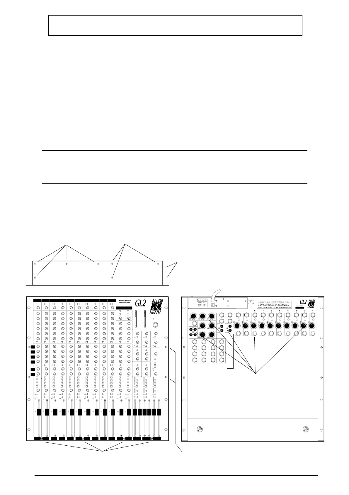
3. REMOVE THE CONSOLE BASE Follow the NUMBER SEQUENCE
INVERT THE CONSOLE
qq
q
qq
AND REMOVE 4x M3 BASE
SECURING SCREWS.
DO NOT REMOVE
THESE 3x POWER
UNIT FIXING SCREWS.
DISCONNECT THE MAINS INPUT, UNPLUG
nn
n
nn
ALL CABLES AND REMOVE THE CONSOLE
FROM THE RACK OR CASE.
REMOVE 2x POWER UNIT
rr
r
rr
SIDE M3 SCREWS.
REMOVE ALL THE JACK NUTS
ss
s
ss
(15mm NUTDRIVER) AND 4AB
CONNECTOR SCREWS (XLRs,
PHONOS).
CAREFULLY LIFT OFF THE
tt
t
tt
BASE.
REMOVE 4x FRONT PANEL M3
pp
p
pp
SCREWS
2
GL2 SYS-LINK EXPANDER OPTION SHEET AP0204 ALLEN & HEATH
REMOVE 4x FRONT PANEL SIDE
oo
o
oo
M3 SCREWS AND NUTS
Page 3

4a. FIT THE SYS-LINK CIRCUIT ASSEMBLY GL2 DIAGRAM 1
Unplug and remove the existing console IDC ribbon harness.
Cut out a section of the earth busbar between stereo channels 11/12 and 13/14 leaving about 3mm
at each end.
Remove the 4x screwlocks from the front of the SYS-LINK D-connectors. Keep these to secure
the connectors after the base is refitted.
Remove the 2x M3x6mm screws from the end of the SYS-LINK assembly spacers.
Position the SYS-LINK assembly between the stereo channels 11/12 and 13/14. Solder the free ends
of the green earth wires to the cut ends of the console earth busbar.
Now mount the SYS-LINK assembly to stereo channel 11/12 using the M3x2mm screws previously
removed through the stereo board holes into the spacers.
4b. FIT THE SYS-LINK CIRCUIT ASSEMBLY GL2-S DIAGRAM 1
Unplug and remove the existing console IDC ribbon harness.
Cut out a section of the earth busbar between stereo channels 15/16 and 17/18 leaving about 3mm
at each end.
Remove the 4x screwlocks from the front of the SYS-LINK D-connectors. Keep these to secure
the connectors after the base is refitted.
Remove the 2x M3x6mm screws from the end of the SYS-LINK assembly spacers.
Position the SYS-LINK assembly between the stereo channels 15/16 and 17/18. Solder the free ends
of the green earth wires to the cut ends of the console earth busbar.
Now mount the SYS-LINK assembly to stereo channel 15/16 using the M3x2mm screws previously
removed through the stereo board holes into the spacers.
5a. SOLDER ON THE SYS-LINK WIRE HARNESS GL2 DIAGRAM 2
Lay the harness above the faders positioning each branch in place against the Group and Master
circuit assemblies.
Solder the prepared ends of the harness wires to their corresponding square solder pads on the Group
assemblies. This may be done with the assemblies in place by carefully using a fine-tipped
soldering iron. Make sure the wiring pads are tinned with fresh solder first for good joints. The
suggested order is :
Group Assembly 1 Pink wire, then Blue, Red, Yellow
Group Assembly 2 Pink, Blue, Red, Yellow
Lift the Master Assembly slightly from the panel to gain access to the wiring pads. Do this by
removing the master control knobs, potentiometer nuts and chrome jack socket nut. Desolder the
earth busbar from the Master assembly.
Solder the harness wires to the wiring pads on the Master Assembly as illustrated. the suggested
order is :
Master Assembly Pink, Blue, Red, Yellow, Brown, Grey
Refit the Master assembly. Make sure that the jack washers, potentiometers and meter LEDs are
correctly positioned in the panel cutouts. Replace the control nuts and knobs.
Resolder the earth busbar to the Master Assembly.
ALLEN & HEATH
GL2 SYS-LINK EXPANDER OPTION SHEET AP0204
3
Page 4

5b. SOLDER ON THE SYS-LINK WIRE HARNESS GL2-S DIAGRAM 3
Lay the harness above the faders positioning each branch in place against the Stereo Return and
L/R circuit assemblies.
Solder the prepared ends of the harness wires to their corresponding square solder pads on the Stereo
Return assemblies. This may be done with the assemblies in place by carefully using a fine-tipped
soldering iron. Make sure the wiring pads are tinned with fresh solder first for good joints. The
suggested order is :
Stereo Return Assembly 1 Pink wire, then Blue, Red, Yellow
Stereo Return Assembly 2 Pink, Blue, Red, Yellow
Solder the harness wires to the wiring pads on the L/R Assembly as illustrated. The suggested order
is :
L/R Assembly Brown *, Grey *, Pink,Yellow, Blue, Red
* Note that the Brown and Grey wires are most easily soldered by applying the iron from the
component side of the L/R assembly which is a through hole plated PCB.
6. FIT THE IDC RIBBON HARNESS DIAGRAM 1
Plug on the IDC ribbon harness supplied with the kit. Make sure that all the pins are correctly aligned
and seated on the circuit assemblies including the SYS-LINK assembly.
Reposition the console power cable as shown in Diagram 1 to avoid it becoming trapped between
the IDC connectors and base.
7. CHECK YOUR WORK AND REFIT THE BASE
Clean out any dirt or debris. Check for correct connector seating, earth busbar and harness wire
connections, and good solder joints. Check that the SYS-LINK assembly and its components are
correctly secured and positioned on the stereo assembly.
Remove the stick-on covers from the D-connector cutouts in the base.
Refit the base making sure that the internal console power cable is correctly positioned.
Fit the 4x screwlocks to the D-connectors to secure them to the base panel.
8. TEST THE CONSOLE
Apply power and test the console for correct operation.
SYS-LINK may be tested by probing the D-connectors or connecting to another GL2 or GL2-S with
the option fitted. A standard 25way male D-type connector cable is required to interconnect
consoles.
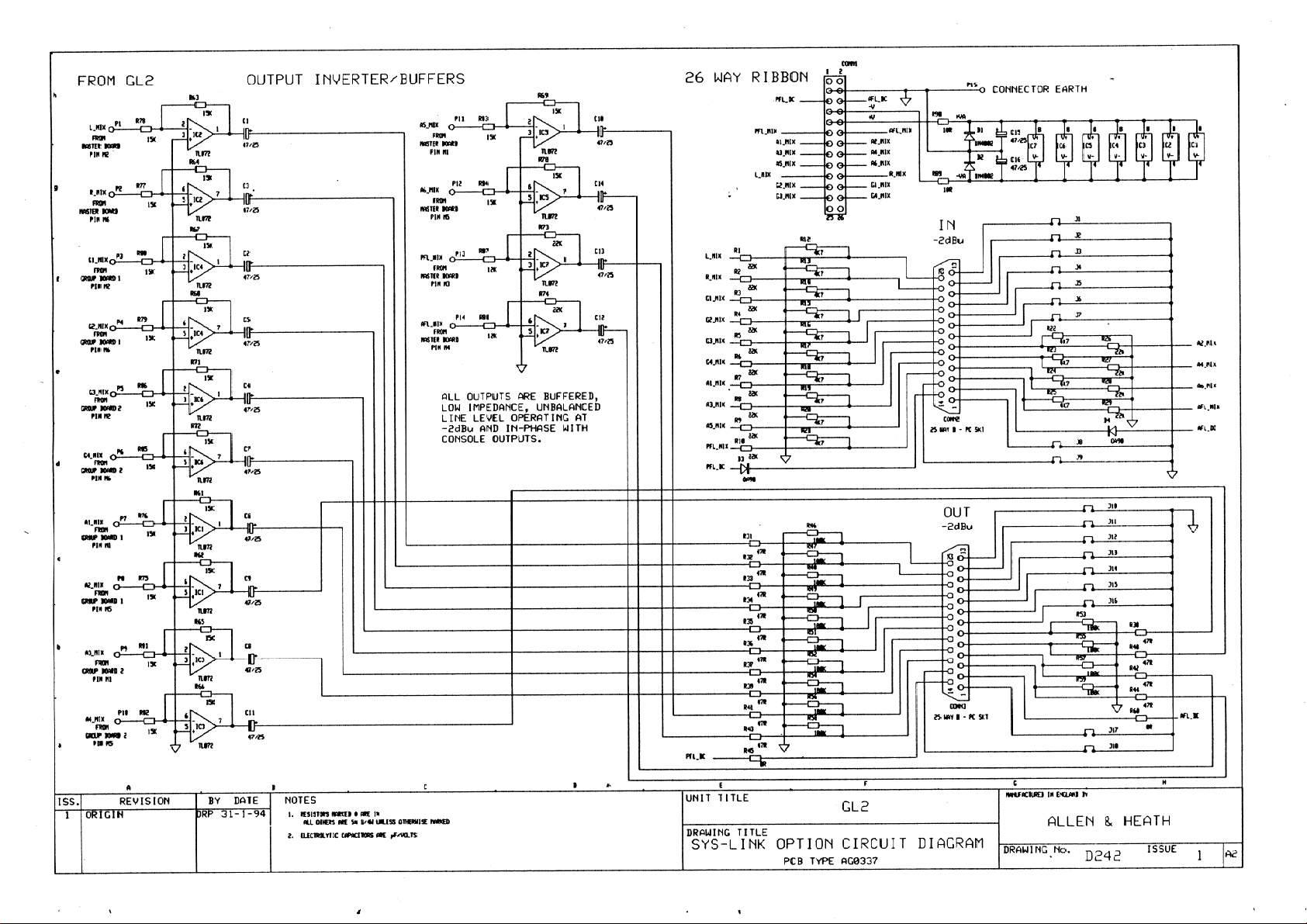
Assembly diagrams 1,2 and 3, circuit diagram and layout, and harness drawing follow for reference.
4
GL2 SYS-LINK EXPANDER OPTION SHEET AP0204 ALLEN & HEATH
Page 5

Page 6

Page 7

Page 8

Page 9
Page 10

 Loading...