

ALLEN&HEATH DR-switch for DR66/128 AP4493 issue 2
User Guide
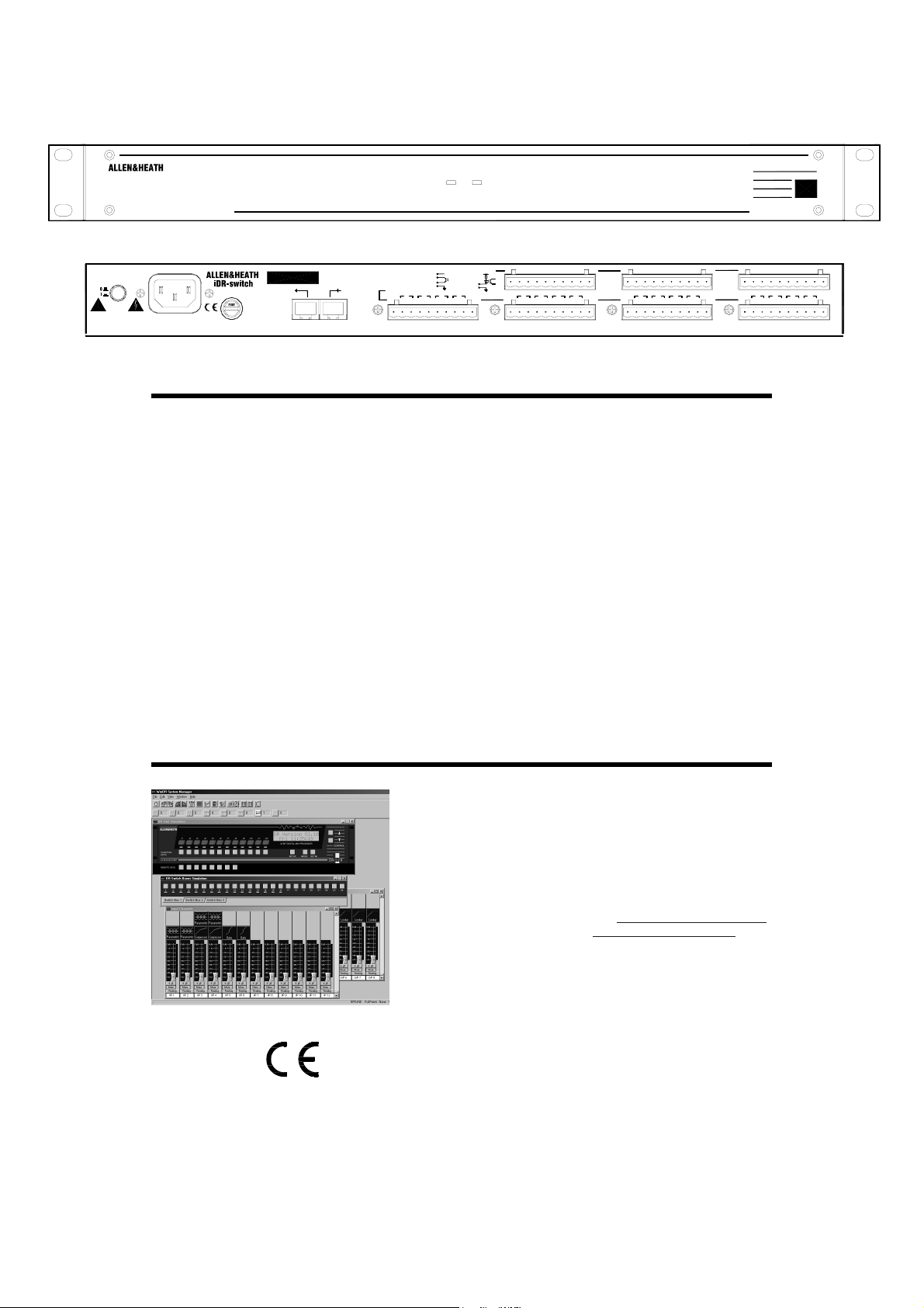
powerlink
24 IN 16 OUT SWITCH CONTROLLER
V
100 - 240V~
47-63Hz ~ 15W MAX
WARNING
THIS APPARATUS MUST BE EARTHED.
ATTENTION: REMPLACER LE FUSIBLE AVEC UN DES MEMES CARACTERISTIQUES.
FOR CONTINUED PROTECTION AGAINST RISK OF FIRE REPLACE FUSE WITH SAME TYPE AND RATING.
CAUTION: RISK OF ELECTR IC SHOCK. DO NOT OPEN. AVIS: RISQUE DE CHOC EL ECTRIQUE - NE PAS OUVRIR. Made in the UK by ALLEN&HEATH LIMITED Complies with UL6500, CSA-E65, EN60065
FUSE: T500mA
next iDR
OUT IN
DR-LINK
+10V DC max total 500mA
+24V DC, 200mA max
LOGIC OUTPUTS
+10V
+
open collector
opto
G
1516 13
+-+-+-+-
Introduction
DR-switch is an add-on unit for the Allen & Heath DR66 and DR128 digital mixers. It provides an additional 24
switch closure control inputs and 16 logic control outputs in a 1U high rack or desk mount case. Up to three
units can be connected providing up to 72 additional switch and 48 additional logic controls. These can be
custom wired by the installer to allow external equipment to control pre-determined mixer functions, or the mixer
to control external equipment. Typical applications include room wall plates for local volume control and source
selection, automatic control of room dividers, projection screens, media players, lamps and other equipment.
The inputs and outputs are opto-isolated to avoid problems with equipment interaction. Grounding the switch
inputs using simple contact closures triggers the programmed mixer function. The logic outputs are open
collector and can be wired to use the internal reference voltage or an external power supply. These typically
drive LED indicators, filament bulbs, relays and circuit logic. Wiring the interface should be carried out by
competent installation personnel. The switch and output functions are easily programmed using the WinDR
software that configures the system.
The DR66/128 communicates with the DR-switch via an RJ45 serial connection running the Allen & Heath DR-
link protocol. A standard 2 metre CAT5 STP cable is provided. However, you can use a cable up to 300
metres long letting you position the unit closer to the local switch wiring. A pass through connection lets you
network up to three units by daisy chaining them. An interface card needs to be fitted to the DR66/128 to
provide the additional serial port. Installation is a straightforward process requiring removal of the DR66/128 top
cover, fitting the internal option card provided and plugging on the cable harness supplied. Refer to Fitting
Instructions sheet AP4615.
SWITCH INPUTS
2K2
switch
G
+10V
opto
910
11
1214
+-+-+-+-
DR-switch
G4321G5678G 1211109 G13141516G 20191817 G21222324
VGVGVG +-+-+-
567+-8
+-+-+-
VG
123+-4
Important Notes
To use the DR-switch the DR66/128 must be running DR
operating software version 2 from V2.11 or greater. DR-switch
will not function using earlier versions of software. Make sure
your PC is running the compatible version of WinDR. Refer to
the Help file provided with the software for details on how to
program the controls. These settings are stored as part of the
DR66/128 mixer patch memories.
The latest version of DR operating software can be downloaded
from the Allen & Heath web site: http://www.allen-heath.com
For technical assistance email support@allen-heath.com
The DR-link interface card fits into the SysNet option slot in the
DR66/128 mixer. This means that you cannot have DR-link
and SysNet installed at the same time. The SysNet protocol
can be run on the RS232 port instead if required.
This product complies with the European Electromagnetic
Compatibility directives 89/336/EEC & 92/31/EEC and the
European Low Voltage Directives 73/23/EEC & 93/68/EEC.
NOTE: Do not remove the cover of the DR-switch unit. There are no user serviceable parts inside. Any
changes or modifications to the unit not approved by Allen & Heath could void the compliance of the equipment
and therefore the users authority to operate it. Whilst we believe the information in this guide to be reliable we
do not assume responsibility for inaccuracies. We also reserve the right to make changes in the interest of
further product development.
Copyright © 2002 Allen & Heath Limited. All rights reserved
.
DR-switch User Guide AP4493 1
Installing the Unit
Connecting Mains Power
100 - 240V~
47-63Hz ~ 15W MAX
FUSE: T500mA
WARNING
THIS APPARATUS MUST BE EARTHED.
ATTENTION: REMPLACER LE FUSIBLE AVEC UN DES MEMES CARACTERISTIQUES.
FOR CONTINUED PROTECTION AGAINST RISK OF FIRE REPLACE FUSE WITH SAME TYPE AND RATING.
CAUTION: RISK OF ELECTRIC SHOCK. DO NOT OPEN. AVIS: RISQUE DE CHOC ELECTRIQUE - NE PAS OUVRIR.
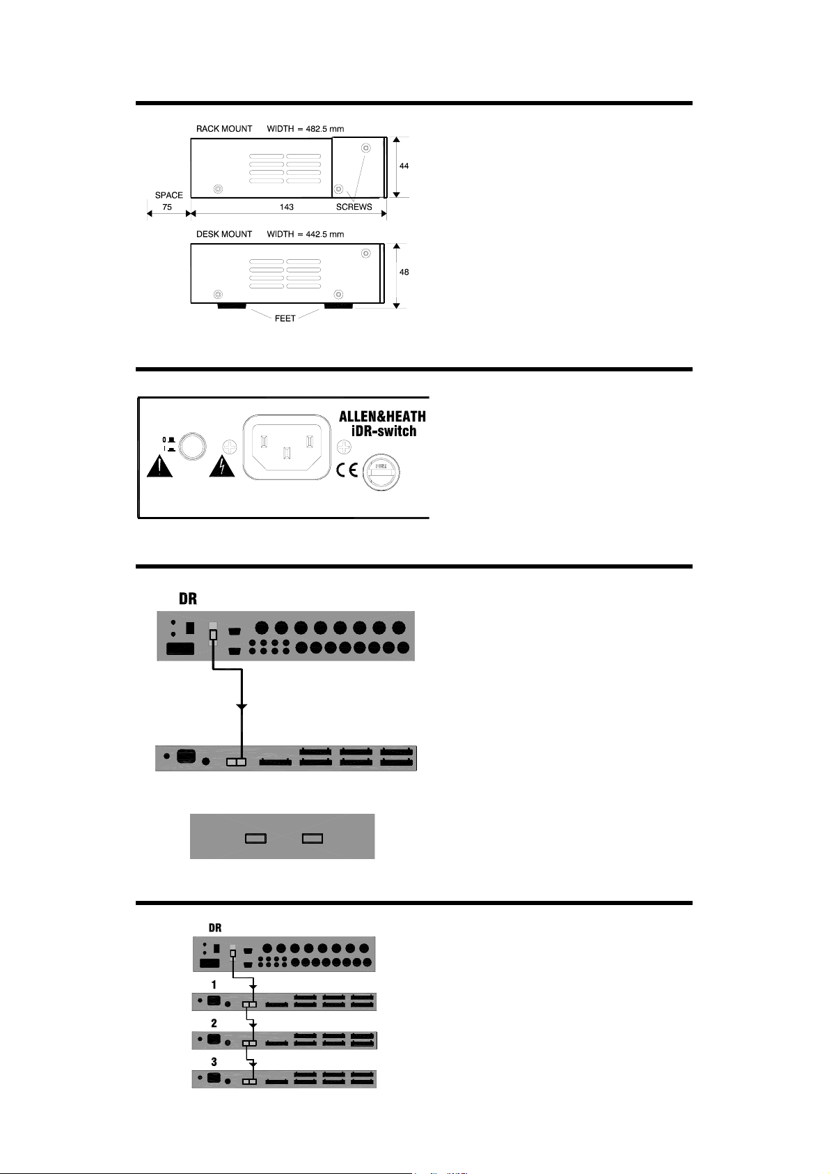
The DR-switch can be rack mounted or free
standing. There are no user controls on the
front panel. Allow a minimum of 75mm
clearance behind the unit for the connectors
and cables. Ensure adequate ventilation to the
side of and behind the unit.
It is shipped with its rack ears fitted and its feet
removed ready to be mounted in a standard
19” equipment rack. 1U rack space is
required.
For desk mount operation remove the two rack
ears using a Torx (star head) T10 screwdriver.
Fit the four plastic feet provided by pressing
them into the underside holes.
Before starting read the Important Safety
Instructions printed on Safety Sheet AP3345
and on the rear panel of the unit. Check that
the correct mains lead with moulded mains
plug and IEC connector has been supplied with
your unit.
With the mains supply turned off plug the IEC
lead fully into the rear panel socket. Apply
power and press the on/off switch to turn the
unit on.
Connecting the DR-switch to the DR66/128
DR-LINK ADAPTER CARD FITTED
RJ45 CAT5 STP CABLE
300m MAX
DR-LINK IN
powerlink
The DR66/128 main unit communicates with
the DR-switch using the Allen & Heath DRLINK serial logic connection. This requires a
standard RJ45 CAT5 STP (shielded twisted
pair) cable. To ensure reliable performance
the cable shield must be attached to the metal
shell of the plugs. Do not use a UTP
(unshielded) cable.
A 2 metre CAT5 cable is provided with the unit.
If you need to connect a longer cable make
sure it is correctly wired to the CAT5 STP
standard. Maximum cable length is 300
metres. Plug one end of the cable into the DRLINK adapter card fitted to the DR66/128. Plug
the other end into the DR-switch DR-LINK IN
socket.
The front panel link LED indicator lights when
communication is established with the
connected DR66/128. The unit features logic
to automatically detect when the system is
powered and operating correctly.
Networking DR-switch Units
FIT DR-LINK ADAPTER CARD
SWITCH 1-24 OUT 1-16
SWITCH 25-48 OUT 17-32
SWITCH 49-72 OUT 33-48
You may connect up to three DR-switch units
to provide up to 72 additional switch inputs and
48 additional logic outputs.
The units are daisy chained by connecting the
DR-LINK OUT of the first unit to DR-LINK IN of
the second and so on.
Maximum distance between each unit and the
next is 300 metres. This lets you position each
DR-switch unit closer the wall plate wiring.
Ensure a good mains supply and solid
grounding to each unit.
DR-switch User Guide AP4493 2

Important: Using the Switch Inputs and Logic Outputs
The DR-switch provides contact closure switch inputs and open-collector logic outputs. How these are wired to
external equipment is the responsibility of the installer. Specification details are provided here for the DR-
switch inputs and outputs. It is important that the installer is suitably qualified and familiar with external control
circuits to be able to work within the capabilities of the unit. Allen & Heath do not assume responsibility for any
damage done to the unit due to incorrect or faulty connection to external equipment.
Planning and Configuring the System
Before starting make sure you have planned how the system is to work. Allocate the switch inputs and logic
outputs and keep a log of their function. The function of each input and output is configured using the Allen &
Heath WinDR software. Refer to the help file within the program for instructions.
Connectors and Grounding
G
Pluggable Phoenix type screw terminal
connectors are used for connecting the
external switches and logic to the DR-switch.
Mating plugs are provided with the unit.
Make sure the wires ends are carefully stripped
and inserted into the terminals. Tighten the
screws using the correct slotted screwdriver.
METAL WALLPLATE
To ensure interference-free operation use
shielded cable. Connect the shields to the
chassis ground screw terminals provided next
LOCAL EARTH BOND
to each connector. Fit the screws with the
shake proof washers provided.
G
For operator safety make sure that
wall plates and other control surfaces made
from metal are correctly bonded to ground
(earth).
Strap the metal plate to the local ground at the
METAL WALLPLATE
wall box. For ground isolation between the
wall plate and equipment rack connect the
cable shield at the DR-switch end only.
CHASSIS EARTH
If a local ground is not available then use the
cable shield to connect the plate to the chassis
of the DR-switch unit as shown. This is not
necessary if the wall plate is made of nonconductive material such as plastic which
insulates it from the operator.
Using the Switch Inputs
The input is opto-coupled to isolate the DRswitch from the connected equipment. It is
INPUTS
+10V
INTERNAL DR-switch CIRCUIT
(1 OF 8 SHOWN)
SWITCH
43215678GG
12 11 10 913141516GG
20 19 18 1721222324GG
2K2
OPTO
SWITCH
DR-switch User Guide AP4493 3
switched by linking its connector pin to the
ground (‘G’) pin. Use a contact closure such
as a momentary press switch to do this.
The input pin is fed from the internal +10V
reference supply through a 2k2 ohm resistor.
Around 5mA maximum current flows when
connected to ground. Combined switch and
cable resistance should not exceed 1k ohm for
the switch to activate.
Each 10way connector provides 8 switch
inputs. Either pin 1 or pin 10 ‘G’ may be used
as the common switch ground. One cable can
feed this ground to a bank of switches. Two
are shown in the diagram here. Do not use the
chassis ground screw which is for cable
shielding and safety earthing only.
For reliable operation we recommend the use
of heavy duty sealed switches.

Using the Logic Outputs
INTERNAL DR-switch CIRCUIT
(1 OF 4 SHOWN)
+10V
V+-G+-+14 13+-15+-16
V+-G+-+10 9+-11+-12
V+-G+-+65+-7
+-8
V+-G+-+21
+-3
+-4
V-G+
OPTO
OPEN COLLECTOR
+10V DC
SUITABLE RESISTORS
-+
+10V DC
LED INDICATORS
LOW CURRENT 12V BULBS
The output is opto-coupled to isolate the DRswitch from the connected equipment. It
provides an open collector output with floating
collector (+pin) and emitter (-pin).
Each 10way connector provides 4 open
collector pairs as well as an internal +10V DC
supply and ground pins. Do not use the
chassis ground screw which is for cable
shielding and safety earthing only.
The output may be used in many ways to
satisfy a wide range of interfacing applications.
It is important that the installer has a good
working knowledge of open collector and
interfacing circuits. Incorrect application may
result in damage to these outputs.
The internal +10V supply may be used as the
power source for low current applications such
as turning on LEDs, lamps and small relays.
One cable can feed the common supply or
ground to a bank of outputs.
V-G+
exceed 500mA. Care must be taken in
component choice to ensure each operates
within its specified capability.
+10V supply for all outputs combined must not
+10V DC
V-G+
SUITABLE RESISTOR
LOW VOLTAGE RELAY
+
-
TO EQUIPMENT
For higher current or voltage applications an
external DC power supply may be used. This
also provides total isolation between the DR-
switch and external equipment.
must not exceed +24V DC. Maximum current
sink through any open collector output must
not exceed 200mA.
A few examples are shown in the diagram
here. For further advice contact Allen & Heath
technical support.
200mA max
CURRENT SINK
DEVICE
GROUND
EXTERNAL POWER SUPPLY
+V (+24V DC max)
System Block Diagram and Specification
G 20191817 G21222324
VOLTAGE
GROUND
+10V
2K2
OPTO-ISOLATED SWITCH INPUTS 1-24
CONTROL
OPTO-ISOLATED LOGI C OUTPUTS 1-16
DC REFERENCE
INTERNAL POWER
CHAIN
Maximum current drawn from the
Maximum external supply voltage
9-16 1-8
OUT INDR-LINK
Connectors:
Pluggable Phoenix 10way terminal
Switch Inputs:
Opto-isolated via 2k2 from +10V
Switch closure connects pin to ground (5mA)
Switch cable resistance up to 1k ohm
Logic Outputs:
Opto-isolated open-collector
Floating collector (+) and emitter (-) pins
Internal 10V DC source (500mA total max)
External DC source (+24V 200mA each max)
DR-switch User Guide AP4493 4
OPEN COLLECTOR
+10V
V+-G13+-14+-15+-16
9-12 5-8 1-4
Communication:
DR-link serial port using RJ45 connectors
Uses Allen & Heath DR-link protocol
2m CAT5 STP cable supplied, maximum 300m
Requires adapter card fitted to DR SysNet port
Daisy chain up to 3 units
Configuration:
Configure with WinDR operating software
Requires V2.11 or greater
Separately configure switches and output
Latched, press, release, time of day action
System:
DR128 8 switch
DR66 12 switch, 4 logic
DR-switch adds 24 switch, 16 logic
Power Supply:
Universal mains input 100-240V.AC
Independent 10V supply for connections
500mA total available
Dimensions:
Rack 482.5 x 143 x 44 mm (1U)
Desk 442.5 x 141 x 48 mm
 Loading...