

Page 1

Firmware Reference Guide
V1.9
This Guide refers to dLive firmware V1.9. Before starting please check
www.allen-heath.com for the latest dLive firmware and documentation.
Issue 2
Page 2

Firmware Reference Guide
2
V1.9
IMPORTANT - Read before starting
ALLEN&HEATH
System operating firmware
The function of dLive is determined by the firmware (operating software) that runs it. Firmware is updated
regularly as new features are added and improvements made.
Check www.allen-heath.com for the latest version of dLive firmware.
Software licence agreement
By using dLive you agree to be bound by the terms of the relevant End User Licence Agreement (EULA),
a copy of which can be found at www.allen-heath.com/legal. You agree to be bound by the terms of the
EULA by installing, copying, or using the software.
Further information
Please refer to the Allen & Heath website for further information, knowledgebase and technical support.
For more information on dLive hardware, system setup and connections please refer to the MixRack and
Surface Getting Started Guides available for download at www.allen-heath.com.
You can also join our Allen & Heath Digital Community to share knowledge and information with other dLive
users.
dLive Firmware Reference Guide
Copyright © 2021 Allen & Heath. All rights reserved.
Allen & Heath Limited, Kernick Industrial Estate, Penryn, Cornwall, TR10 9LU, UK
http://www.allen-heath.com
Page 3

Firmware Reference Guide
3
V1.9
Contents
IMPORTANT - Read before starting ............................................................................................................ 2
System operating firmware .................................................................................................................... 2
Software licence agreement .................................................................................................................. 2
Further information ................................................................................................................................ 2
Contents ....................................................................................................................................................... 3
1. Processing screen ........................................................................................................................... 6
1.1 Harmony UI ............................................................................................................................. 6
1.2 Copy/Paste/Reset, Setup, Listen and Lib keys ....................................................................... 9
1.3 Bank view .............................................................................................................................. 10
1.4 Overview ............................................................................................................................... 12
1.5 Preamp ................................................................................................................................. 14
1.6 Ext In ..................................................................................................................................... 17
1.7 Filter ...................................................................................................................................... 18
1.8 Gate (Ducker / Expander) ..................................................................................................... 19
1.9 Inserts and Dyn8 ................................................................................................................... 22
1.10 PEQ ....................................................................................................................................... 24
1.11 NEQ ...................................................................................................................................... 25
1.12 Compressor .......................................................................................................................... 27
1.13 Delay ..................................................................................................................................... 28
2. System screen ............................................................................................................................... 29
2.1 Harmony UI ........................................................................................................................... 29
2.2 Home .................................................................................................................................... 30
2.3 User login .............................................................................................................................. 31
3. Meters ............................................................................................................................................ 32
3.1 RTA ....................................................................................................................................... 33
4. FX .................................................................................................................................................. 35
5. I/O .................................................................................................................................................. 37
5.1 Inputs .................................................................................................................................... 37
5.2 Outputs ................................................................................................................................. 38
5.3 Tie Lines ................................................................................................................................ 39
5.4 Virtual SoundCheck .............................................................................................................. 40
6. Routing .......................................................................................................................................... 41
7. Scenes ........................................................................................................................................... 45
7.1 Scene Manager ..................................................................................................................... 45
7.2 Recall Filters .......................................................................................................................... 47
7.3 Embedded Recall ................................................................................................................. 48
7.4 Update .................................................................................................................................. 49
7.5 Cue List Editor....................................................................................................................... 51
7.6 Scene Import ........................................................................................................................ 52
7.7 Global Scene Safes .............................................................................................................. 53
7.8 Role Filters ............................................................................................................................ 54
8. Ganging ......................................................................................................................................... 55
9. MixRack Setup ............................................................................................................................... 56
9.1 Config / Mixer Config ............................................................................................................ 56
9.2 Config / IP Stereo Config ...................................................................................................... 57
9.3 Config / Name & Colour ........................................................................................................ 58
Page 4

Firmware Reference Guide
4
V1.9
9.4 Config / Network ................................................................................................................... 59
9.5 Config / User Profiles ............................................................................................................ 60
9.6 Config / RF Devices .............................................................................................................. 62
9.7 Audio / I/O Port ..................................................................................................................... 63
9.8 Audio / Audio Sync ............................................................................................................... 64
9.9 Audio / Source Select ........................................................................................................... 65
9.10 Audio / AMM ......................................................................................................................... 66
9.11 Talkback................................................................................................................................ 70
9.12 Mute Groups ......................................................................................................................... 72
9.13 SigGen .................................................................................................................................. 73
9.14 Controllers / Device Manager................................................................................................ 73
9.15 Controllers / Quick Setup ...................................................................................................... 75
9.16 Controllers / Advanced ......................................................................................................... 76
9.17 Controllers / Simulator .......................................................................................................... 77
10. Surface Setup ................................................................................................................................ 78
10.1 Control / Strip Assign ............................................................................................................ 78
10.2 MIDI Strips ............................................................................................................................ 79
10.3 Control / SoftKeys ................................................................................................................. 80
10.4 Control / Surface Preferences ............................................................................................... 81
10.5 Control / Dimmer ................................................................................................................... 82
10.6 Control / DCA/MCA Options ................................................................................................. 82
10.7 Audio / PAFL ......................................................................................................................... 84
10.8 Audio / SIP ............................................................................................................................ 85
10.9 Audio / USB Audio ................................................................................................................ 86
10.10 Audio / I/O Port ..................................................................................................................... 87
10.11 Audio / Audio Sync ............................................................................................................... 87
10.12 Audio / Metering Ballistics ..................................................................................................... 88
10.13 Config / Network ................................................................................................................... 89
10.14 Config / Target MixRack ........................................................................................................ 90
10.15 External Screen ..................................................................................................................... 90
10.16 Controllers............................................................................................................................. 90
11. Shows / Utility ................................................................................................................................ 91
11.1 Memory / Show Manager ...................................................................................................... 91
11.2 Memory / Library Manager .................................................................................................... 92
11.3 Utility / History ....................................................................................................................... 93
11.4 Utility / Date/Time .................................................................................................................. 94
11.5 Utility / Calibration ................................................................................................................. 94
11.6 Utility / Diagnostic ................................................................................................................. 94
11.7 Utility / Firmware ................................................................................................................... 94
11.8 Control / MIDI ........................................................................................................................ 96
12. Appendix A – DEEP Processing and RackExtra FX ....................................................................... 98
12.1 DEEP Processing Preamp models........................................................................................ 98
12.2 DEEP Processing Compressor models ................................................................................ 99
12.3 DEEP Processing GEQ models .......................................................................................... 103
12.4 DEEP Processing AMM ....................................................................................................... 104
12.5 RackExtra FX models .......................................................................................................... 106
13. Appendix B – Scene and Show memory content ........................................................................ 123
13.1 Scene memories ................................................................................................................. 123
13.2 Show files ............................................................................................................................ 124
13.3 Settings not stored in Shows .............................................................................................. 125
Page 5

Firmware Reference Guide
5
V1.9
14. Appendix C – Template Shows .................................................................................................... 126
14.1 FoH ..................................................................................................................................... 126
14.2 Mon ..................................................................................................................................... 126
14.3 Surround ............................................................................................................................. 126
14.4 FoH LCR+ .......................................................................................................................... 126
14.5 Multi-Surface FOH/MON ..................................................................................................... 127
15. Appendix D – I/O Port Options..................................................................................................... 128
15.1 ACE ..................................................................................................................................... 128
15.2 AES XLR .............................................................................................................................. 128
15.3 DX Link ................................................................................................................................ 129
15.4 gigaACE / fibreACE ............................................................................................................. 130
15.5 MADI ................................................................................................................................... 131
15.6 superMADI .......................................................................................................................... 132
16. Appendix E – Multi-Surface .......................................................................................................... 134
16.1 Overview ............................................................................................................................. 134
16.2 Example Applications ......................................................................................................... 134
16.3 Network Configuration ........................................................................................................ 134
16.4 Connection.......................................................................................................................... 134
16.5 gigaACE I/O Module Configuration ..................................................................................... 135
16.6 fibreACE I/O Module Configuration ..................................................................................... 135
16.7 PAFL ................................................................................................................................... 135
16.8 Surface I/O .......................................................................................................................... 135
16.9 Shows ................................................................................................................................. 135
16.10 Scenes ................................................................................................................................ 136
16.11 Surface Roles ...................................................................................................................... 136
16.12 Firmware Update ................................................................................................................ 136
16.13 Patching between Surfaces ................................................................................................ 136
16.14 gigaACE I/O Module Channel Mapping .............................................................................. 137
17. Appendix F – MCAs ..................................................................................................................... 138
17.1 Overview ............................................................................................................................. 138
17.2 Adding MCA Members ........................................................................................................ 138
17.3 Enabling MCA Mode ........................................................................................................... 138
17.4 Working in MCA Mode ........................................................................................................ 138
18. Block diagram .............................................................................................................................. 139
19. Processing specs ........................................................................................................................ 140
Page 6
Firmware Reference Guide
6
V1.9
1. Processing screen
1
2
3
4
6
4
3
1
5
2
The left screen on the S5000, S7000 and C3500 is dedicated to channel processing. The S3000, C1500
and C2500 incorporate processing into the System screen.
1.1 Harmony UI
dLive integrates the touchscreen with a set of ‘wrap-around’ controls colour-coded for intuitive and quick
operation. Dedicated areas of the screen display values and status of the corresponding controls; some
are configurable or user assignable (widget areas).
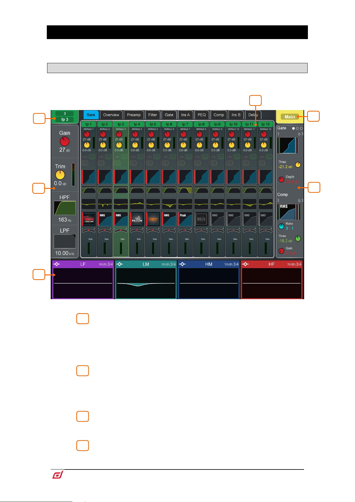
Selected channel – Displays the name, colour, type and number of the
currently selected channel. Tap to edit channel name and colour. 7 colours and off
are available.
A name can have up to 8 characters, however only the first 6 characters will be
displayed in the fader strip LCD. To store a name for instant access later on, touch a
‘quick name’ box and touch Store.
Active Mix – Displays the name, colour, type and number of the currently
active Mix. If a DCA Spill is active on the Surface, the Mix name is surrounded by a
red square.
Be aware of which mix is currently active. It is good practice to turn off the Mix
key to return to the main mix once you have finished adjusting a mix.
Main screen area – Touch any of the tabs at the top of the screen to open
a specific processing block or page. Alternatively, tap on any of the widget areas
described below to open any associated processing page in the main screen area.
Preamp and Filters – Displays the preamp meter and values for the Input
Channel Gain, Trim, HPF and LPF controls. The HPF and LPF graphs are greyed out
Page 7

Firmware Reference Guide
7
V1.9
when the associated filter is off. The controls are hidden where not available, for
5
example when a Mix channel or DCA is selected.
You can tap on this area to select the preamp or filters when using the
Copy/Paste/Reset or Listen keys.
South Area – User assignable area, typically used for displaying the PEQ
parameters and/or response curve. Press the View key to toggle between the
configured views.
⚙ To configure, hold down the Setup key and touch this area, drag the required
views from the left to the right of the screen, touch these to set any option or
preference, then touch Apply to confirm.
The South Area configuration is stored in Shows, not in Scene memories.
You can tap on this area to select the PEQ when using the Copy/Paste/Reset or
Listen keys.
The following views are available in this version of firmware:
Individual PEQ Bands – Displays the response of each PEQ band. Frequency and
gain values are temporarily shown when a setting is adjusted.
Multiband PEQ Graph – Full range PEQ view. The individual effect of each band is
shown as fill colours, while the overall response curve is shown as a yellow line.
Frequency and gain values are temporarily shown when a setting is adjusted.
PEQ Values Only – Displays value bars for Gain, Width and Frequency.
PEQ with RTA – Displays the PEQ as in the Multiband PEQ view, with an overlayed
RTA. .
RTA – Configurable RTA view, can use RTA 1 or 2 and provide any of the RTA views
(Bar, Line or Sonogram), or follow the setting of the main RTA selected.
Meters – Scrollable meter-bridge widget showing signal level, gain reduction, gate
activity, channel names and colours. Can be set to display Inputs, FX Returns, Mixes,
AMM or any of the 4 User Meter views. The tap-off point for the meters can be chosen
for Input, Mixes and User views. The channel name background is red when the
channel is muted via the channel mute, DCA mute or mute group.
Page 8

Firmware Reference Guide
8
V1.9
General Information – Displays a number of different configurable console
Gate and
Comp
Gate with signal
meter, graph,
gain reduction
meter,
Threshold and
Depth control;
Compressor
with signal
meter (pre and
post), graph,
gain reduction
meter, Ratio,
Threshold and
Gain control.
Gate
Signal meter,
graph, gain
reduction
meter,
sidechain
graph,
histogram,
Threshold,
Depth, Hold,
Attack and
Release
control.
Comp
Signal meter,
(pre and
post), graph,
gain
reduction
meter,
sidechain
graph,
histogram,
Ratio,
Threshold,
Gain, Attack
and Release
control.
6
parameters including the Last Recalled, Next and Selected Scene information, clock,
current user and current firmware.
Automation and Clock – Fixed format version of General Information, showing Last
Show, Last, Selected and Next Scene along with a large real time clock.
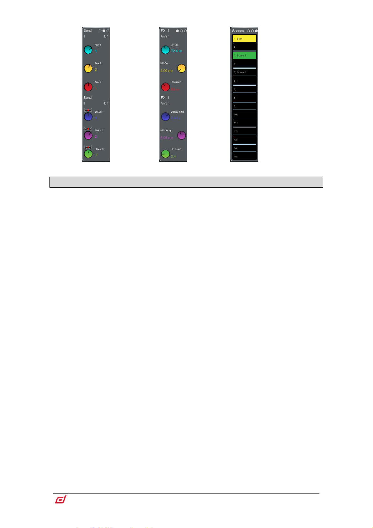
Soft Rotaries – Displays the parameters for the assigned controls and
meters or thumbnail graphs where applicable. Press the keys on top of the rotaries,
or swipe within the widget area to toggle between the 3 available layers.
Soft Rotaries can be set to follow channel selection, active Mix or to be locked to a
specific channel. Their assignments and settings are stored in Scene memories.
⚙ To configure, hold down the Setup key and touch this area, drag the required
widgets from the left to the right of the screen, check for any option or preference,
then touch Apply to confirm.
The following widgets are available in this version of firmware:
Page 9
Firmware Reference Guide
9
V1.9
Send levels
Configurable
widget with up
to 6 sends,
typically for
monitor use or
FX sends.
FX
Controls of 6
key
parameters
for a chosen
FX unit.
Scenes
Scrollable
scene list.
Touch a
Scene to
select.
The selected
Scene is
highlighted
in yellow.
The Next or
‘Go’ Scene is
highlighted
in green.
1.2 Copy/Paste/Reset, Setup, Listen and Lib keys
The following keys can be used in conjunction with the touchscreen:
Copy – Hold down and touch any highlighted area of the screen to copy the settings of a specific
processing block. A temporary message will appear at the bottom of the screen to confirm the operation.
Paste - Hold down and touch any highlighted area of the screen to paste copied settings. A temporary
message will appear at the bottom of the screen to confirm the operation.
Reset - Hold down and touch any highlighted area of the touchscreen to reset the associated parameters
to factory default. A temporary message will appear at the bottom of the screen to confirm the operation.
⚙ Setup – Hold down and touch any highlighted area of the screen to configure it. For example, touch a
widget area to set up functions, views or controls. Touch on the main screen area to access options further
to those displayed.
Listen – Hold down and touch any highlighted area of the screen to listen to the selected channel at that
point in the signal path. The signal temporarily overwrites the PAFL bus and associated meters. Press the
PAFL Clear key or touch the screen popup to cancel.
Lib – Press to access the Library window for the current page. Libraries let you store and recall presets for
individual processing blocks such as EQ and Compressor, and also for the whole Input or Mix channel.
Input and Mix channel processing Libraries are accessed from their Overview page.
The Library window shows 3 types of Library: Factory, User (stored in the mixer) and USB (stored in the
USB key). Touch to select a Library item and use the buttons to Recall, Overwrite or Delete. Touch Store
New to store a new item and use the keypad to apply a name. Use the
Manager
Help – Press to display a contextual help for the current screen.
to organize or transfer your Libraries.
Shows/Util / Memory / Library
Page 10

Firmware Reference Guide
10
V1.9
1 2 3
4
1 4 2
3
1.3 Bank view
The Bank view provides an at-a-glance overview of all channels assigned to the active fader Bank and
Layer. It follows both channel selection and Layer selection, so that it always displays the channels you are
working on.
The Bank view can be used with the Copy/Paste/Reset and Listen keys, for example for copying a single
processing block to one or multiple channels. See the paragraph above for details on using these keys.
Input channels – Displays name and colour, source type, preamp meter, gain,
+48V and polarity, gate graph, filters, PEQ graph, compressor graph, Pan and
channel meter. The channel name is framed in orange when Virtual Soundcheck is
active.
Tap on a channel to select. The selected channel is highlighted in green.
Tap on a processing block within a selected channel to open the associated
page.
Gang membership of channels is shown next to the Gain control.
Pull down the name of a selected Input channel, or swipe down with two fingers
anywhere in the Bank view to display details of the sources such as socket numbers.
Pull / swipe down again to restore the normal view. Use the
Preamp screen to patch sources.
I/O or Processing /
Page 11

Firmware Reference Guide
11
V1.9
1
2
3
4
4
1
2
3
DCAs – Displays name, colour, members (assigned channels) and whether the
‘Fader to Zero dB’ and ‘MCA’ options are enabled. Use the
Surface Assign keys to assign channels.
Routing screen or the
List of members. Scroll the list up or down if the members are too numerous
to fit in the strip.
Tap to enable MCA mode on a DCA. MCA mode can be set globally on all
DCAs in
See Appendix F in this guide for more details on MCA functionality.
Surface / Control / DCA/MCA Spills.
Tap to enable the DCA Fader to Zero dB mode on a DCA. This forces the DCA
fader to 0dB.
Mix channels – Displays name and colour, Ext Input, meter (pre-processing),
polarity, PEQ graph, compressor graph, and channel meter (post-processing).
Pull down the name of a selected Mix channel to display details of the Ext Input
source such as socket number. Pull down the name again to restore the normal view.
Use the
I/O or Processing / Ext In screen to patch sources.
Page 12

Firmware Reference Guide
12
V1.9
1.4 Overview
1
2
3
4
5
3
1
4 2 5
The Overview page provides an at-a-glance view of all processing for the selected Input or Mix channel.
Touch a section to open the related page.
Press the Lib key while on the Overview page to access the channel Library. Enable the Recall Preamp
option to include Preamp settings when recalling the Library. Channel Libraries do not store routing, levels
or assignments.
Input channels
Preamp – Displays the Preamp source, Gain and Digital Trim. Icons show
48V phantom power and polarity setting.
Processing – Thumbnail graphs of Filters, PEQ, Gate and Compressor
complete with sidechain. EQ and filter curves display yellow when switched In and
grey when switched Out. Dynamics display blue when switched In and grey when
switched Out.
Insert – Assignment and bypass status are shown for the two Insert points.
Delay – Shows the setting for the selected channel.
Library – Opens the Input Channel Library.
Page 13

Firmware Reference Guide
13
V1.9
Mix channels
1
2
3
4
5
3 1 4
2
5
Ext In – Displays the External Input source, Gain and Digital Trim. Icons show
48V phantom power and polarity setting.
Processing – Thumbnail graphs of PEQ, NEQ and Compressor complete
with sidechain. The PEQ curve and GEQ sliders display yellow when switched In and
grey when switched Out. The compressor graph displays blue when switched In and
grey when switched Out.
Insert – Assignment and bypass status are shown.
Delay – Shows the setting for the selected channel.
Library – Opens the Mix Channel Library.
Page 14

Firmware Reference Guide
14
V1.9
1.5 Preamp
1
2
3
1 7 2
4
8
5 3 6
The Preamp page provides access to the Input Channel source patching and other Input settings.
Source Select – Open the drop-down menu to choose which source to
patch to the channel, touch the Socket box then turn the screen Rotary to select the
required socket or number, then touch Apply.
Sources that can be patched include MixRack sockets, Surface sockets, DX Expander
inputs, Mix Busses, PAFL busses, USB stereo playback, I/O Port inputs, the output of
built-in effects (Rack FX), and the Signal Generator.
When patching from a DT168 or DT164-W expander, preamp controls will appear
when a valid patch is made from a DT socket, via a Dante card, to the input channel.
Ensure the correct patch is made in both Dante Controller and the dLive’s I/O page.
To provide a simple starting point, the Template Show default is one-to-one mapping
of sockets to channels.
Socket Preamp – If the patched source is a Mic/Line XLR input then its
Preamp controls are shown. These provide remote control of the input preamp circuit
located at the socket. Pad switches in a 20dB input attenuator, and the combined
Gain + Pad value is shown in the Gain box. Touch and hold the 48V button for 1
second to enable or disable phantom power.
Enable the Scene Recall Safe option to make the Preamp Gain, Pad and 48V settings
safe from Scene Recall. This can be useful when splitting the same mic preamp to two
or more channels.
Making a channel Safe using the Surface Safe key automatically makes the
associated Preamp safe. Turning off Safe using the surface key unsafes the Preamp.
RF Info – If the patched source is associated with an
the RF Info box is shown. Channel name, mute status, battery level, RF signal strength
and receiver audio level/peak information is displayed. Touch anywhere in the RF Info
box to open the External Device Channel window.
RF Device Channel then
Page 15

Firmware Reference Guide
15
V1.9
4
5
6
In addition to the information shown in the RF Info box, channel RF frequency is
displayed as well as several options:
Locate - When enabled, Locate flashes the front panel lights of the selected
channel’s RF receiver until the Locate button is turned off.
Up - Turns up the RF receiver gain on the selected channel in +1dB increments.
Down - Turns down the RF receiver gain on the selected channel in -1dB
increments.
Mute - Toggles the selected channel’s RF receiver Mute status.
Close – Close the External Device Channel window and return to the Preamp page.
Stereo Image – If the channel is configured as stereo then the Stereo Image
settings are shown. Mode selects normal stereo input (L/R), reversed stereo input
(R/L), stereo with inverted Left polarity (L –Pol/R), reversed stereo with inverted Right
polarity (R –Pol/L), mono sum (Mono), Left as mono source to both sides (L/L), Right
as mono source to both sides (R/R), Middle/Side decode to stereo (M/S) with the first
input of the pair acting as the MID signal and the second signal of the pair acting as
the SIDE signal. Width adjusts the Stereo Image from 0% (mono) to 100% (stereo).
Preamp On Surface – Lets you choose whether the fader strip rotaries
control the Preamp Gain or channel Trim when in Gain mode. Turn on Enable Preamp
on Surface for normal, single console operation. Turn it off to prevent accidental Gain
changes in situations where the same preamp is shared between FoH and Monitor
consoles. When off, the dedicated Preamp rotary control is disabled and a warning
pop-up appears any time the Gain setting is adjusted on screen.
⚙ Hold down Setup and touch anywhere in the Preamp screen to access a global
setting for disabling Preamp on Surface. This affects all channels.
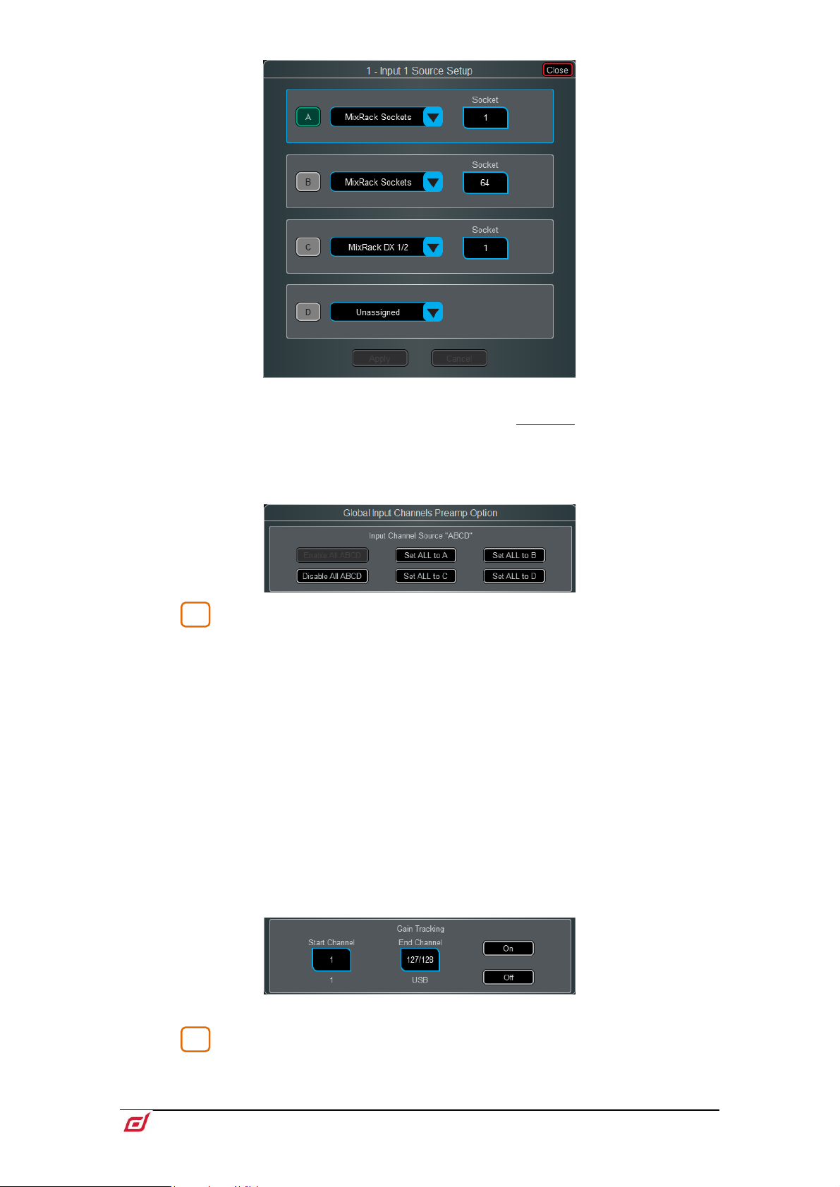
Enable ABCD – Turn on Enable ABCD to activate ABCD inputs on the
selected channel.
Select A, B, C or D to enable that source to the selected input channel.
Select ABCD Source Setup to access patching for each of the A,B,C & D inputs on
the selected channel.
Page 16
Firmware Reference Guide
16
V1.9
7
8
Select A, B, C or D to enable that source to the selected input channel.
Patching to ABCD inputs can also be performed via the I/O screen.
Select Disable ABCD to deactivate ABCD inputs on the selected channel.
⚙ Hold down Setup and touch anywhere in the Preamp screen to access global
settings for enabling and disabling ABCD on Input Channels. This affects all channels.
Trim – Trim provides +/- 24dB control in addition to the Preamp Gain or when
the source does not have a preamp (for example inputs from an I/O Port). Trim is part
of the channel, not the preamp, and is therefore useful in situations where the preamp
is shared between FoH and Monitor consoles.
When Gain Tracking is activated, Trim automatically changes to compensate for
preamp gain changes.
Gain Tracking may be used:
- In Multi-Surface mode, with up to 4 Surfaces.
- Between MixRacks connected via gigaACE cards with Gain Sharing turned on
in the I/O Port settings.
- Between dLive and Avantis consoles, when sharing DT168 and DT164W
preamps.
⚙ Hold down Setup and touch anywhere in the Preamp screen to define a Gain
Tracking channel range. This allows the operator to quickly enable or disable Gain
Tracking across a range of channels.
A post-Trim signal meter is shown. Polarity toggles normal and reverse.
Preamp Model – Displays the DEEP Processing model and controls, if one
is loaded. Press the Lib key to access the preamp Library and load a preamp model
such as a Dual Stage Valve.
Page 17
Firmware Reference Guide
17
V1.9
1
2
3
1
2
3
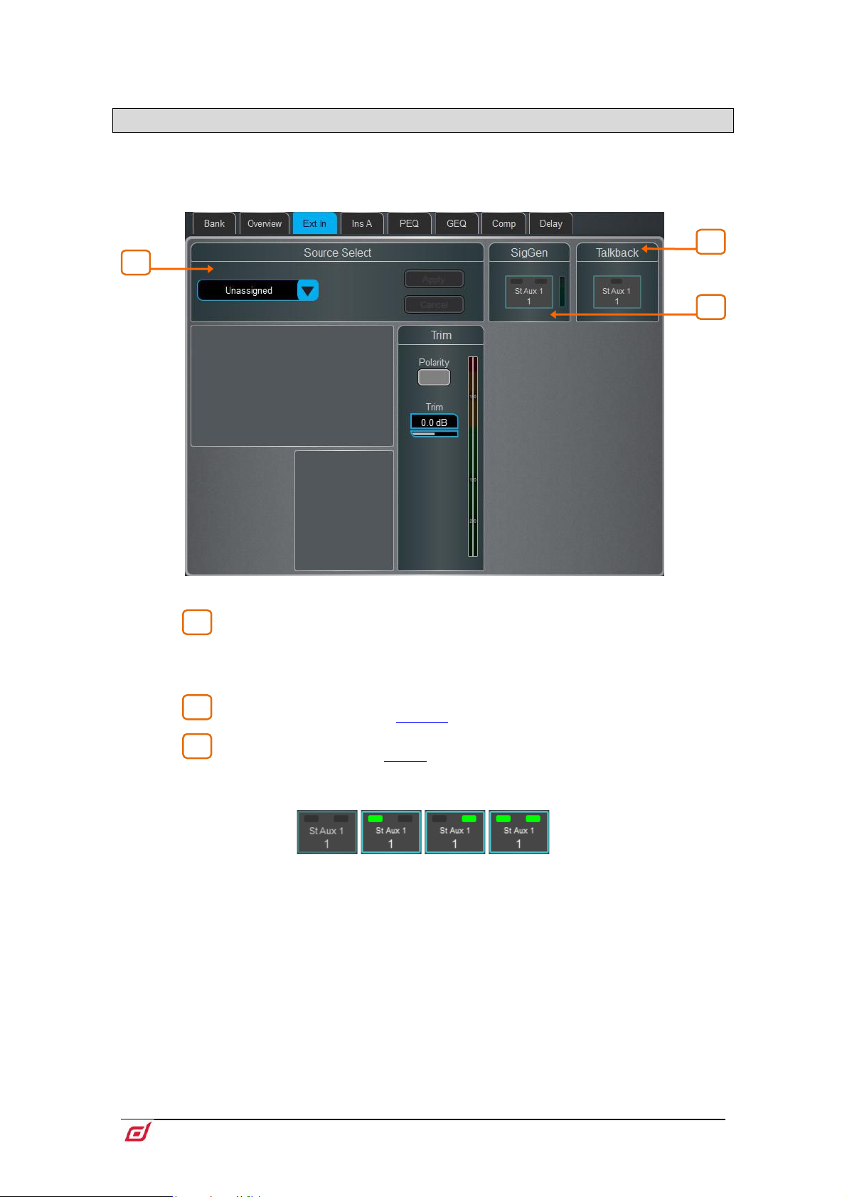
1.6 Ext In
You can assign an external input to any Mix channel, for example for bus summing, combining console
outputs, or external communications. In addition to sockets, Mix and PAFL buses can also be selected as
external inputs. The Ext Input sums with the Mix channel pre-insert and is affected by the Mix processing
and fader.
Source Select – Open the drop-down menu to choose which source to
patch to the channel, touch the Socket box then turn the screen Rotary to select the
required socket or number, then touch Apply. Socket Preamp and Trim controls are
shown when an Ext In is assigned.
Talkback – Touch to toggle
Talkback ON/OFF to the selected Mix channel.
SigGen – Touch to toggle SigGen ON/OFF.
The SigGen can be sent to one or both sides of a stereo Mix channel by touching the
left and/or right side of the button.
Page 18

Firmware Reference Guide
18
V1.9
1.7 Filter
1
2
3
1
3
2
The Filter page provides access to the HPF and LPF filters.
Graph – Touch and drag the HPF (green) or LPF (yellow) dots to adjust the
filter cut-off frequency.
HPF – The frequency for the High Pass Filter is adjustable from 20Hz to 2kHz,
and the Slope can be selected from 12dB/octave to 24dB/octave. Two filter types are
available: Butterworth (optimized frequency response) and Bessel (optimized phase
response).
LPF – The frequency for the Low Pass Filter is adjustable from 20Hz to 20kHz.
The slope is fixed 12dB/octave.
Page 19
Firmware Reference Guide
19
V1.9
1.8 Gate (Ducker / Expander)
1 2 3
1
3
2
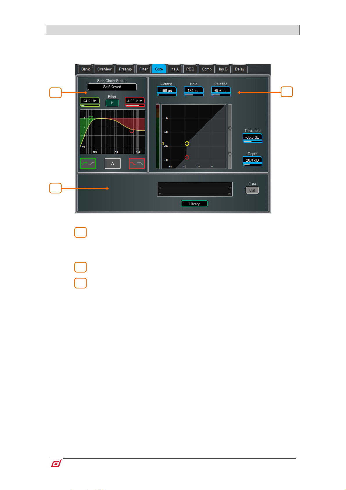
This page provides access to the Input channel Gate settings and sidechain filter.
Press the Lib key to access the Gate Library. This is also where you can recall a ducker or expander to
replace the gate.
Side Chain – Touch the Side Chain Source box to open a window for
selecting the Key (trigger) input to the Gate. An adjustable BPF, HPF and LPF filter or
shelf can be switched in to limit the frequency range of the Key signal. The curve turns
yellow when the filter is switched in.
Histogram – Shows Gate activity over time.
Gate Settings – Touch and drag in the graph or touch a parameter box and
use the screen rotary do adjust.
Threshold sets the level at which the gate opens to let the signal through. The meter
on the left lines up with the graph and shows the signal at the input to the gate. The
gain reduction meter on the right shows when the gate is closed. Depth sets how
much the signal is attenuated when the gate closes. Attack, Hold, Release set how
fast the gate opens when the signal rises above the threshold, how long it is held open
after the signal falls below the threshold, and how long it takes to attenuate after it
closes.
Page 20
Firmware Reference Guide
20
V1.9
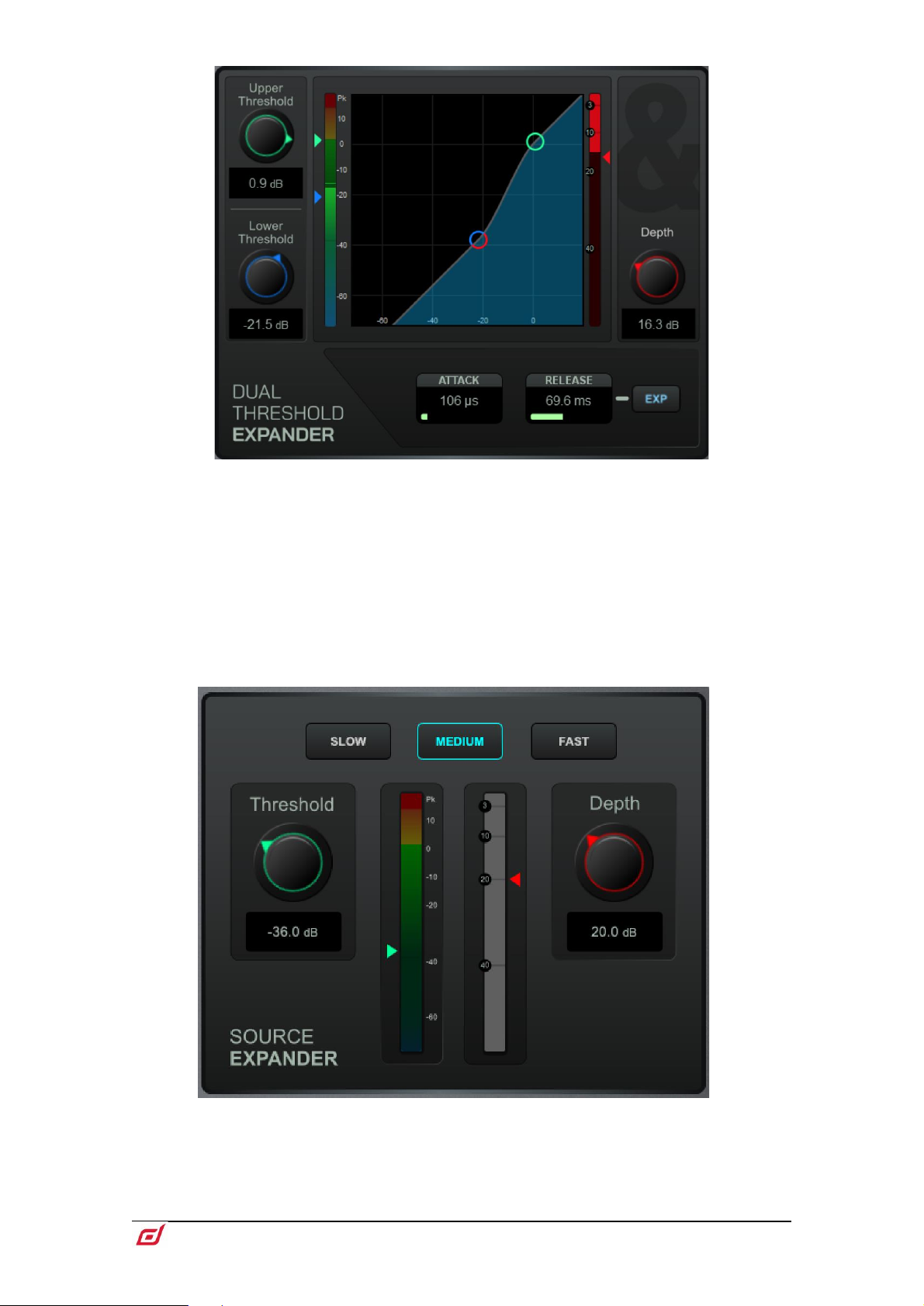
Dual Threshold Expander Settings - Touch and drag in the graph or touch
a parameter box and use the screen rotary to adjust. Upper Threshold sets the level
at which the expander begins to fully open. Lower Threshold sets the level at which
the expander begins to reduce the gain to the full Depth as specified on the right. The
expander can be made more aggressive by putting the two thresholds close together,
or less aggressive by having them further apart. The Attack and Release parameters
allow you to choose how quickly the expander begins to respond after the signal
passes the thresholds and how quickly the expander gain reduction changes after it
responds. The EXP button selects either a Linear or Logarithmic response to the
signal passing the threshold.
Source Expander Settings - Touch a parameter box and use the screen rotary
do adjust. Choose the Threshold at which you would like the expander to operate
along with the depth (amount) of gain reduction and the speed (Slow, Medium or
Fast) of its response rate.
Page 21
Firmware Reference Guide
21
V1.9
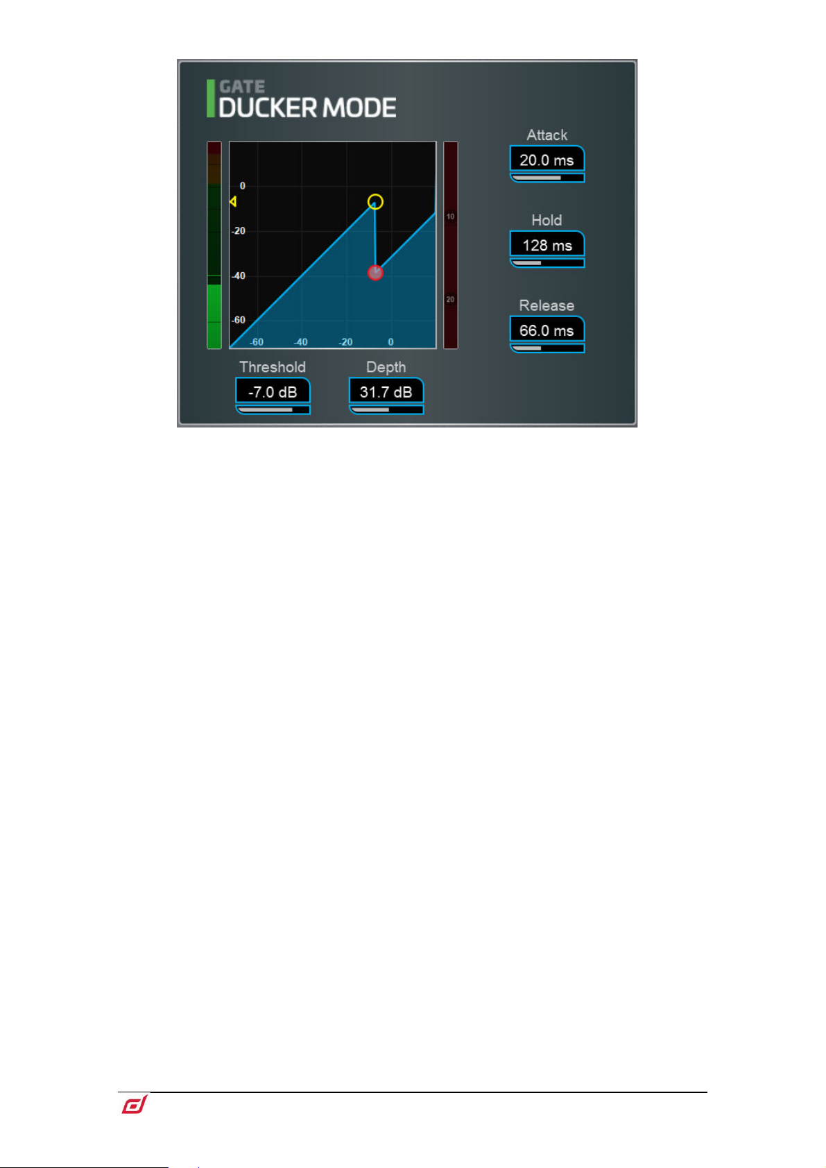
Ducker settings - Touch and drag in the graph or touch a parameter box and use
the screen rotary do adjust.
Threshold sets the level at which the Ducker starts to attenuate the signal. The meter
on the left lines up with the graph and shows the signal at the input to the Ducker. The
gain reduction meter on the right shows when the Ducker is active. Depth sets how
much the signal is attenuated when the Ducker is active. Attack, Hold, Release set
how fast the Ducker operates when the signal rises above the threshold, how long it
is held after the signal falls below the threshold, and how long it takes to attenuate.
It is typical for a Ducker to be keyed from an external Side Chain Source, for example
a background music channel set to duck when a presenter microphone exceeds a
given threshold.
Page 22
Firmware Reference Guide
22
V1.9
1.9 Inserts and Dyn8
1
2
1
2
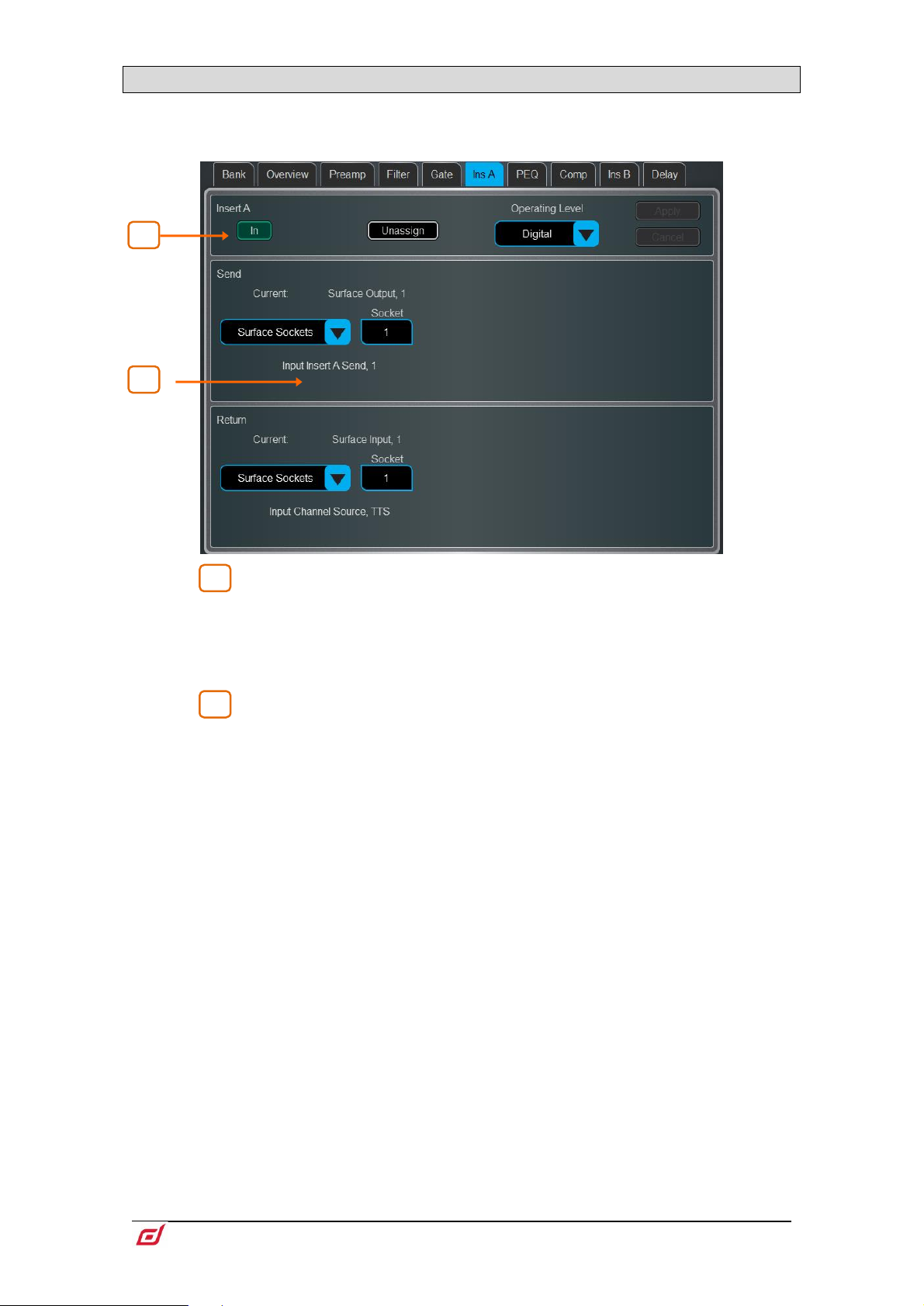
You can insert external equipment, external plugins, one of 64 internal Dyn8 engines, or one of 16 internal
RackExtra FX units into a channel. Input channels provide two Insert points (post Gate and post
PEQ/Comp).
Insert Settings – Press In to switch the inserted device in circuit. Choose
the Operating Level of the insert point: Digital sends the signal at 0dB for use with
external digital equipment via AES3 or I/O Ports; Analogue compensates for the
+4dBu nominal level on the XLR outputs, so that the overall gain of the insert circuit
is 0dB; -10dBV is a standard for consumer equipment. Press Unassign to clear the
current Insert assignment.
Insert Patch – Use the drop-down menus to assign the Send and Return
to physical sockets, I/O Ports, Dyn8 engines or FX units. Touch the boxes and use the
screen rotary to select socket or number. When assigning Dyn8 engines, the system
automatically selects the next available (unassigned) engine. Touch Apply to confirm.
If an internal RackExtra FX is assigned, the controls for the device are displayed in the
Insert screen for convenience, together with a button to access the FX Library and a
Dry/Wet control to adjust the balance of direct and effect signal.
Page 23
Firmware Reference Guide
23
V1.9
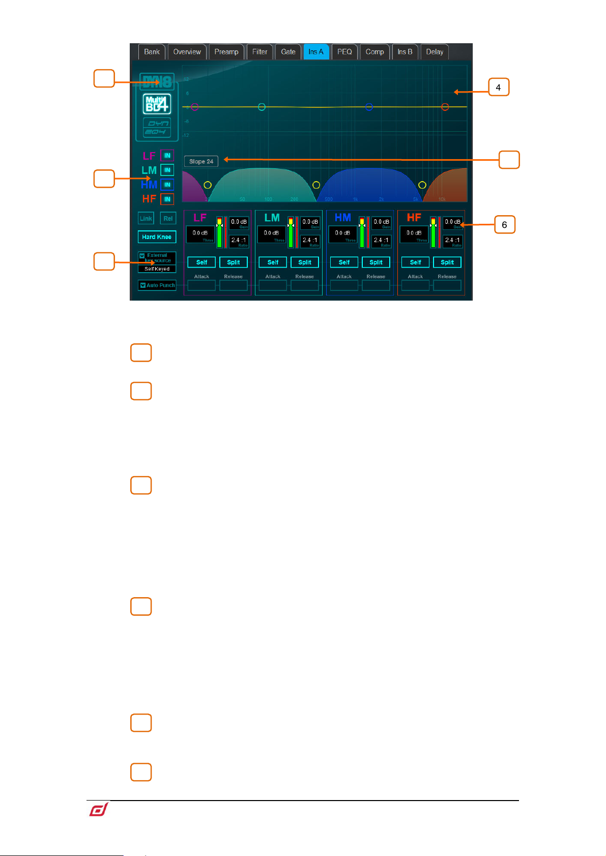
Dyn8
1
2
3
4
5
6
4
1
5
2 3 6
Each engine offers 4 bands of multiband compression and 4 bands of dynamic EQ.
Select view mode: multiband controls, dynamic EQ controls, or a graphic
overview of both.
Per-band bypass controls.
The multiband view has also controls of compression Knee (Hard or Soft), an option
to Link all parameters across bands for quick setup, and a Rel option to link all
parameters whilst keeping the relative offset.
The dynamic EQ view has an option to select the function of the screen rotary (Freq
or Gain) when a band is selected in the graph.
Select the External Key Source. Each band can be set to operate with the
selected key source or Self keyed. The key signal frequency range is selectable per
band with Split (key signal frequency range defined by band crossover/width settings)
and Wide (full 20Hz-20kHz bandwidth) options.
Set the desired ballistics mode. There are two manual (Peak, RMS) and four automatic
modes (Punch, Opto, Slow, Fast) for the multiband compressor, with the manual
modes providing per-band Attack and Release time. The dynamic EQ offers two per-
band ballistic modes: Std 9 (standard, smooth frequency conscious release) or Fast
9 (fast release).
The multiband graph displays the resulting crossover frequency response.
Shaded fills show dynamic gain reduction. The yellow curve shows makeup gain for
each band, and the blue curve shows maximum potential gain reduction.
The dynamic EQ graph displays the 4-band frequency response, with the shaded fills
showing dynamic activity and the solid outline showing maximum cut/boost for each
band.
Touch and drag the points to adjust frequency values. To avoid accidental changes,
the Gain can only be controlled in Director or by using the screen rotary.
Choose the crossover Slope: - 6, 18, or 24 dB/oct. Slope 6 has minimal phase
summing distortion and is typically used for programme mastering. Slope 18 and 24
provide more band isolation and work well for vocal and instrument control.
Per-band controls of threshold, gain (multiband), ratio (multiband), width
(dynamic EQ).
Page 24
Firmware Reference Guide
24
V1.9
The dynamic EQ Gain set in the graph is the maximum amount of compression (cut)
1
2
1
2
or expansion (boost) for the band when the sidechain signal level is Above or Below
the threshold setting, depending on settings.
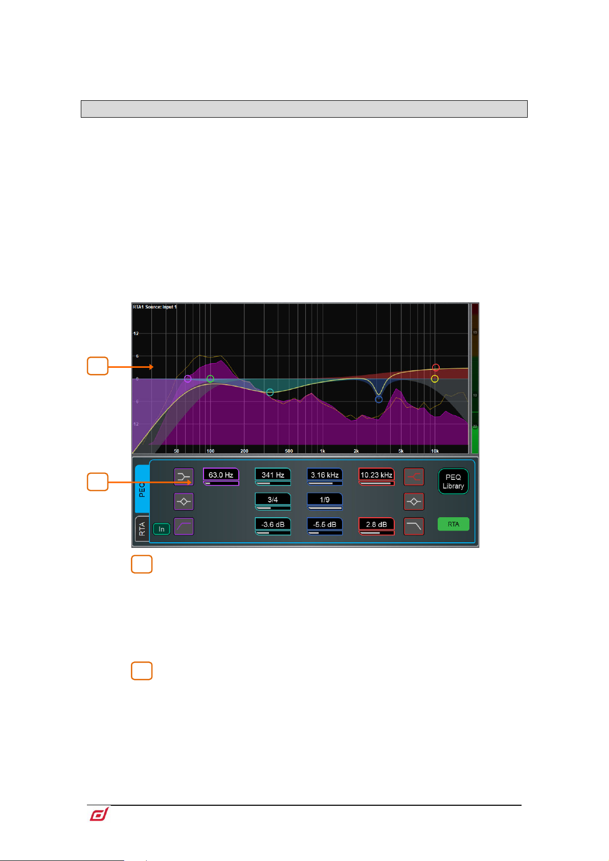
1.10 PEQ
The Parametric Equaliser provides 4 fully adjustable bands of equalisation. It can be adjusted using
dedicated rotary controls on the surface or using the touchscreen.
⚙ Hold down Setup and touch the navigation tabs area to access channel options
including the processing order of PEQ and Compressor. The default order is PEQ first,
Compressor next. You can invert the order on a per channel basis or globally.
The PEQ/Comp order for each channel is stored in Show files. It is not stored in
Scene memories.
⚙ Hold down Setup and touch anywhere in the PEQ screen to access the Global
Input Channels PEQ Options. Enable Width Latch (C Class Surfaces only) changes
the behaviour of the physical Width button on the Surface from momentary to latching.
Fill Curves displays the individual response of the 4 PEQ bands and HPF / LFP filters
with shaded colours. The frequency range for the 4 bands may be set globally for all
Input or Mixes to be limited or Full Range.
Graph – Touch and drag the 4 band dots to adjust their centre frequencies.
Touch and drag the HPF / LPF dots to adjust their cut-off frequencies. The overall
frequency response curve turns yellow when the PEQ is switched in and grey when
switched out. The RTA1 can be overlayed in the graph.
Note that the RTA Source is displayed in the top left corner of the graph and may
not be the currently selected channel, depending on the RTA1 settings.
PEQ Settings – Frequency sweeps the shelving, centre or cut-off frequency
for each band. Width adjusts the width in octaves of the bell shaped EQ band. Gain
allows up to +/-15dB boost or cut for each band. The LF and HF EQ bands can be
set as shelving, bell shaped or low/high cut 12dB/octave filters.
Page 25
Firmware Reference Guide
25
V1.9
1 2 3
1
3
2
RTA Settings – Touch RTA to enable or disable the RTA overlay.
Set the Min and Max Scale to adjust for sensitivity or signal level. Touch Position and
drag the RTA area on the graph to locate and resize the overlay. You can also control
the Opacity of the overlay. Select the view Type (Bar, Line or Sonogram) - this is
independent from the Type selected in the main RTA1 screen.
For a detailed description of the RTA graph and other settings, please refer to the
Meters chapter later in this guide.
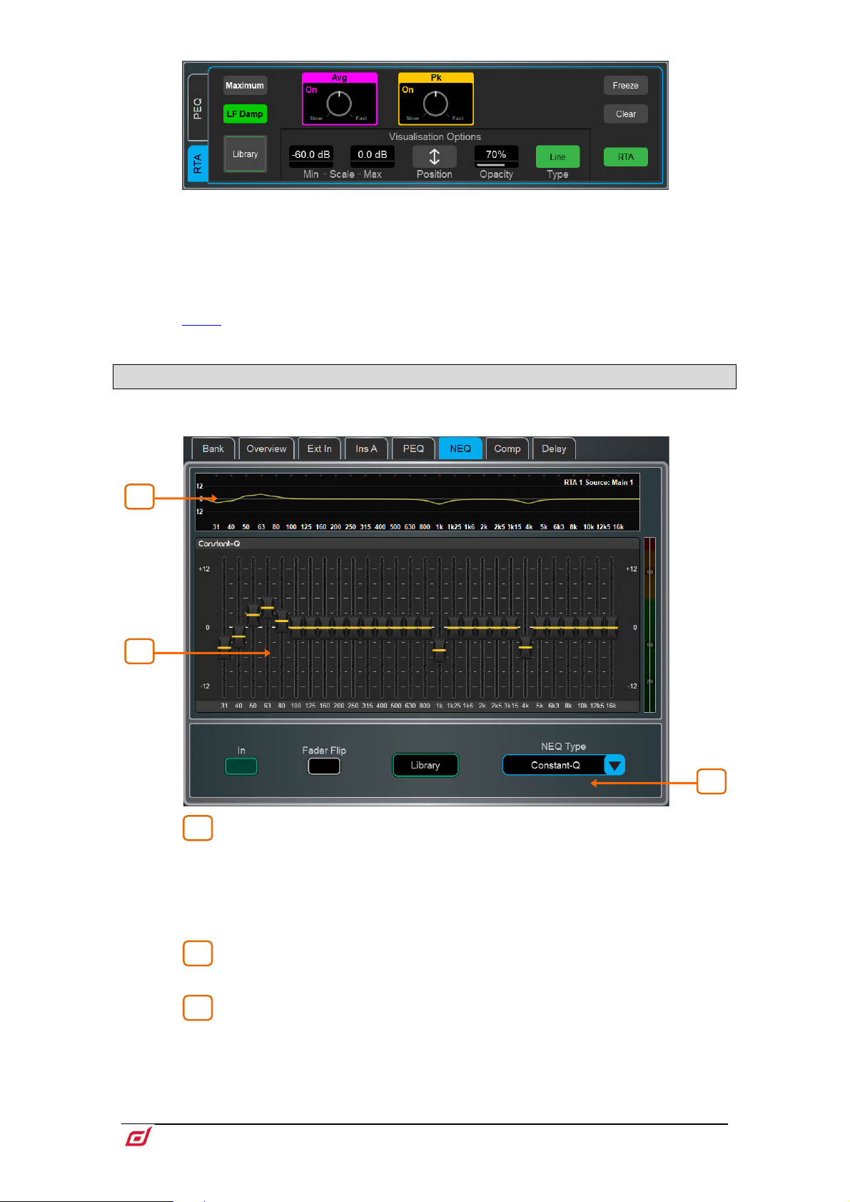
1.11 NEQ
A choice of 28-band 1/3 octave Graphic Equaliser or 12-band PEQ is provided on each of the Mix outputs.
It can be adjusted using the touchscreen or the Surface faders.
GEQ Graph – The top part of the screen shows the combined frequency
response curve of the GEQ. The curve turns yellow when the GEQ is switched in and
grey when switched out. The RTA1 is overlayed on this graph, with peak band
indication.
Note that the RTA Source is displayed in the top right corner of the graph and may
not be the currently selected channel, depending on the RTA1 settings.
GEQ Sliders – Touch a frequency slider to select and drag it up / down or
use the screen rotary to adjust the gain.
GEQ Settings – Press Fader Flip to control the GEQ with the Surface
faders. The fader strips and their LCD displays show the settings of the GEQ frequency
bands, while the right hand fader becomes the master for the selected Mix and the
channel meters display the RTA for the currently selected RTA1 source. Press Fader
Flip again to toggle between frequency banks and back to normal mixing. Select
Library to open the NEQ Libraries or NEQ Type to select a different DEEP Processing
GEQ model or 12-band PEQ.
Page 26

Firmware Reference Guide
26
V1.9
See Appendix A in this guide for more details on GEQ models.
4
5
4
5
NEQ12 Graph – Touch and drag the 12 band symbols to adjust their centre
frequencies. The overall frequency response curve turns yellow when the PEQ is
switched in and grey when switched out. The RTA1 can be overlayed in the graph.
Note that the RTA Source is displayed in the top left corner of the graph and may
not be the currently selected channel, depending on the RTA1 settings.
NEQ12 Settings – Use the tabs to navigate through the controls for the 12
available bands. Each tab uses a different symbol for the frequency bands, and
colours for easy identification.
Frequency sweeps the shelving, centre or cut-off frequency for each band. Width
adjusts the width in octaves of the bell shaped EQ band. Gain allows up to +/-15dB
boost or cut for each band. The LF and HF EQ bands can be set as shelving, bell
shaped or low/high cut with selectable 12/24/48dB /octave filters.
Select NEQ Library to open the NEQ Libraries or NEQ Type to switch to a GEQ
model.
RTA Settings – Touch RTA to enable or disable the RTA overlay.
Set the Min and Max Scale to adjust for sensitivity or signal level. Touch Position and
drag the RTA area on the graph to locate and resize the overlay. You can also control
the Opacity of the overlay. Select the view Type (Bar, Line or Sonogram) - this is
independent from the Type selected in the main RTA1 screen.
For a detailed description of the RTA graph and other settings, please refer to the
Meters chapter later in this guide.
Page 27

Firmware Reference Guide
27
V1.9
1.12 Compressor
1
2
3
4
1
3
2
4
This page provides access to the channel Compressor settings and sidechain filter.
⚙ Hold down Setup and touch the navigation tabs area to access channel options
including the processing order of PEQ and Compressor. The default order is PEQ first,
Compressor next. You can invert the order on a per channel basis or globally.
The PEQ/Comp order for each channel is stored in Show files. It is not stored in
Scene memories.
Several DEEP compressor models are available including emulations of classic industry standards. These
can be recalled via Library presets and include the option of a channel Ducker to replace the Compressor.
Touch the Library button or press the Surface Lib key to access the available Libraries.
See Appendix A in this guide for more details on Compressor models. See the
Gate section earlier in this guid for more details on the Ducker.
Side Chain – Touch the Side Chain Source box to open a window for
selecting the Key (trigger) input to the Gate. An adjustable BPF, HPF and LPF filter or
shelf can be switched in to limit the frequency range of the Key signal. The curve turns
yellow when the filter is switched in.
Parallel Path – Lets you balance the dry ‘uncompressed’ signal with the
compressed output. When turned off, only the compressed signal is routed to the
output.
Compressor Settings – Touch and drag in the graph or touch a
parameter box and use the screen rotary do adjust.
Threshold sets the level at which the compression starts. The meter on the left lines
up with the graph and shows the signal at the input to the compressor. The gain
reduction meter on the right shows how much the signal is being compressed. Ratio
sets the amount of compression when the signal exceeds the threshold. A ratio of 1:1
means no compression. Set Ratio to ‘Infinity’ to use the compressor as a limiter. Gain
is the make-up gain to compensate for the drop in overall volume after compression.
Soft Knee adds compression gradually with gentler ratio as it approaches the
threshold. Attack and Release control how fast the compressor pulls back the signal
when it exceeds the threshold and how long it takes to let go when the signal drops
below the threshold.
Compressor Histogram – Shows Compressor activity over time.
Page 28

Firmware Reference Guide
28
V1.9
1.13 Delay
The delay settings for all the channels or mixes are shown on this page, with the currently selected channel
highlighted. Use the screen rotary to change its value, or touch another parameter box to adjust the delay
for a different channel. Touch the In buttons to toggle the delay in or out. Input delays can be adjusted up
to 340ms, Mix delays up to 680ms.
⚙ Hold down Setup and touch anywhere in the Delay page to access the unit and
temperature preferences for the Delay. The default unit is ms but can be changed to
metres, feet, or samples. This can be changed globally for the Input channels and for
the Mix channels. Enter the ambient temperature if using distances so that dLive can
compensate for the effect on delay.
Page 29

Firmware Reference Guide
29
V1.9
2. System screen
1
2 3 4
5
6
4
3
1 5 2
The right screen on the S5000, S7000 and C3500 gives access to system settings, FX, meters, routing and
I/O. The S3000, C1500 and C2500 incorporate the Processing screen into this screen.
2.1 Harmony UI
Selected / Last Recalled Scene – Displays the currently Selected
Scene in yellow, or Last Recalled Scene in blue (refer to the
guide for details). The Selected Scene is highlighted in yellow in the Scene list.
Scenes chapter in this
Next Scene – Displays the Scene next to be recalled when pressing Go.
Main screen area – Press the Screen mode keys to select pages and
menus displayed in this area.
Scenes widget – Scrollable scene list. Touch a Scene to select. The
selected Scene is highlighted in yellow. The Next or ‘Go’ Scene is highlighted in green.
South Area – User assignable area. Press the View key to toggle between
the configured views.
⚙ To configure, hold down the Setup key and touch this area, drag the required
views from the left to the right of the screen, touch these to check for any option or
preference, then touch Apply to confirm.
Available views are listed in paragraph 1.1.
Page 30

Firmware Reference Guide
30
V1.9
Soft Rotaries – Displays the parameters for the assigned controls and
6
1
2
3
4
2
1
3
meters or thumbnail graphs where applicable. Press the keys on top of the rotaries,
or swipe within the widget area to toggle between the 3 available layers.
Soft Rotaries can be set to follow channel selection, active Mix or to be locked to a
specific channel.
⚙ To configure, hold down the Setup key and touch this area, drag the required
widgets from the left to the right of the screen, check for any option or preference,
then touch Apply to confirm.
Available widgets are detailed in
paragraph 1.1.
2.2 Home
When no screen mode is selected, the System screen displays a Home page with a System Status
dashboard, real time clock and access to User login.
Press the Surface Home key to come back to this page and present a familiar state
of the Surface controls. Pressing this key will exit from any screen mode or menu,
unselect the currently selected channel, make the Main LR the active Mix, and Layer
A active across all fader banks.
System Status – Displays a list of system components. A green tick
indicates the component is running correctly. A red cross indicates that an error is
detected. A blue icon appears when a non-critical event is logged. Touch the
component to display further information.
System Info – Displays firmware version, current User, and the last Scene
and Show recalled.
When a system component is selected in the left column, further information on that
component is displayed here, for example status of PSU, cable redundancy, Audio
Sync Lock and the type of I/O modules fitted in a DX32 Expander.
If an error is detected, touch Dismiss to clear the error from this screen, or open the
Utility / Utility / History page to investigate the logs. Contact Support for assistance.
Press Switch User to access the User login page.
Page 31

Firmware Reference Guide
31
V1.9
Press Lock Surface and confirm to lock all Surface controls and touchscreen.
4
1
2
1
2
Parameters will not be changed if the Surface controls are moved while locked, for
example when left unattended. Touch the screen again to unlock the Surface.
If a password is set for the current User, then this must be entered when the User
locks or unlocks the Surface.
Press Power Down and confirm to safely power down the system before you switch
power off. Failures to power down correctly may result in recent parameter changes
being lost or under rare circumstances, possible data corruption.
Clock – Shows the time in hours, minutes, seconds. Set using the
Utility / Date/Time
screen.
Utility /
2.3 User login
The system Administrator can set up to 9 User Profiles to protect settings and restrict access to certain
functions. Touch Switch User on the Home page to log in as a different User.
Users list - Shows available Users. These can be configured and enabled
in the
MixRack / Config / User Profiles screen. The Admin User is always displayed.
Icons indicate if the User has a password or User Scene set. Touch a User to select
then touch Login to change User.
If a password is set, it needs to be entered using the screen keypad when the User
logs in using this screen, when the system is powered up, or when the User locks or
unlocks the Surface.
User Scene – If one is set, it is recalled automatically on login when the
User is changed. It is not recalled when the Surface is unlocked, or when the system
is powered down and up again while the same User is current.
Page 32
Firmware Reference Guide
32
V1.9
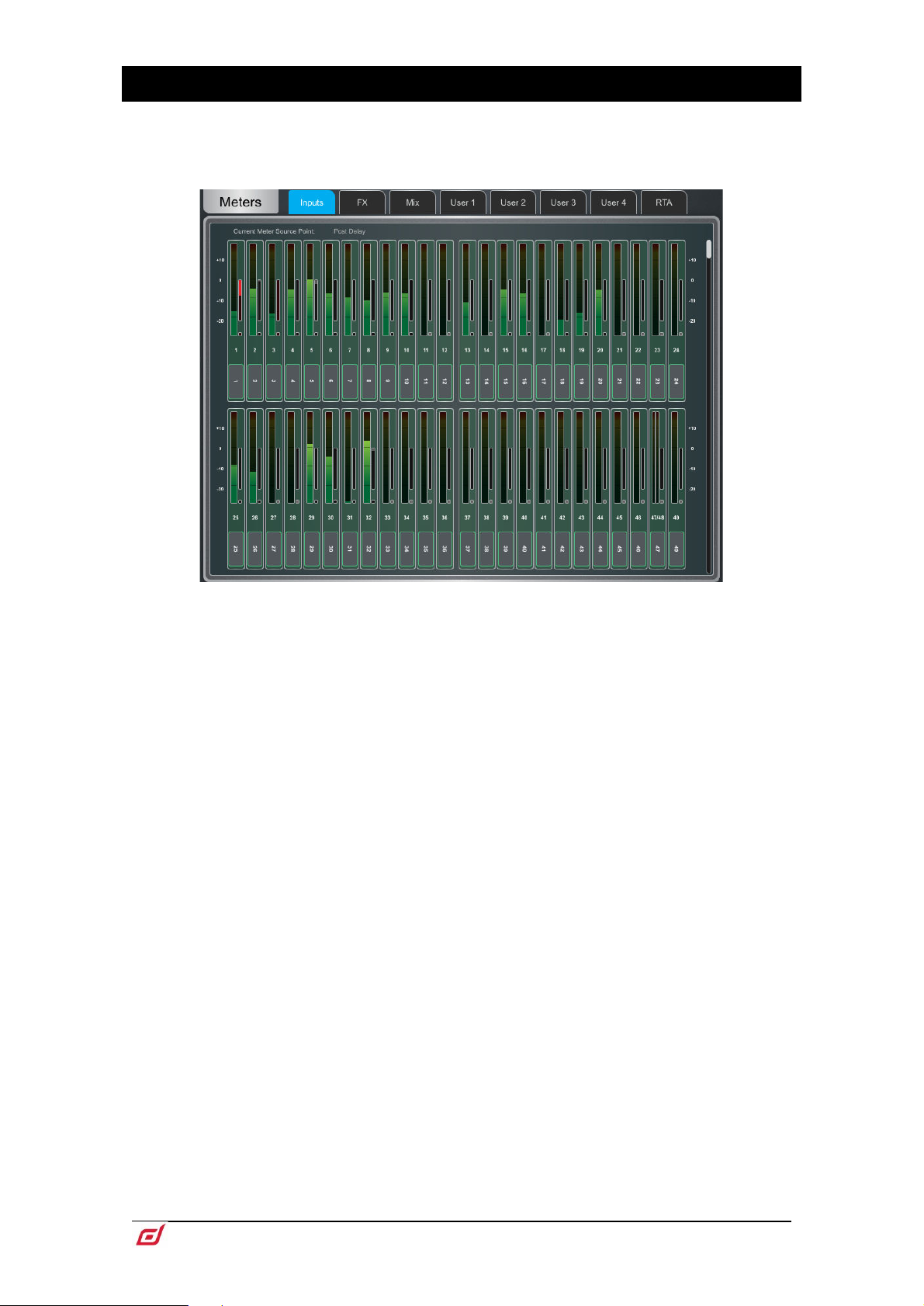
3. Meters
Different tabs give access to meters for all Input channels, all FX Sends and Returns, all Mixes, and up to 4
configurable User views, as well as two Real Time Analysers.
Meters tabs – Channel name and colour are shown below each meter. The channel
name background is red when the channel is muted via the channel mute, DCA mute
or mute group.
A gain reduction meter and gate active indicator are also displayed, these show
activity in red when switched In, and in grey when switched out.
The meter source point can be globally set for all Inputs and all Mixes independently.
This does not affect the fader strip meter on the Surface or any other screen metering.
⚙ Hold down Setup and touch anywhere in the Inputs or Mix meter tab to set the
associated source point. This will affect the Surface LED meters too. Options available
for Inputs are Post Preamp, Post Gate/PEQ, Post Compressor, Post Delay. Options
available for Mixes are Post Preamp, Post Insert Return, Post PEQ, Post NEQ, Post
Compressor, Post Fader.
⚙ Hold down Setup and touch anywhere in a User tab to configure the User view.
Touch a channel to configure, add spacers or rows as required, and press Apply to
confirm.
Page 33
Firmware Reference Guide
33
V1.9
3.1 RTA
1
2
3
4
2
1
3
4
Two Real Time Analysers are available and can be locked to a specific channel or set to follow
channel selection and PAFL.
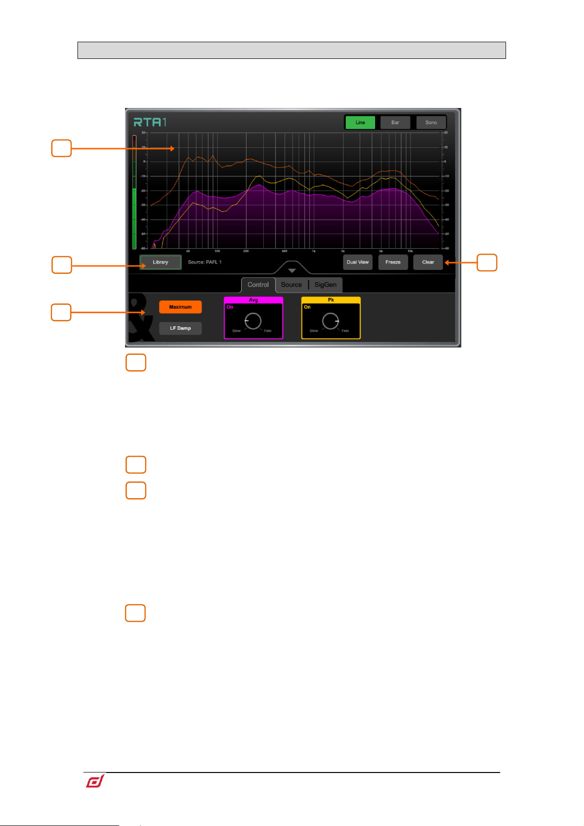
RTA Graph – A 61 band Real Time Analyser or Sonogram is displayed here.
Select the view mode in the upper right corner.
In Line mode, the Average (RMS) curve in purple and the Peak curve in yellow show
current energy in dB for each frequency. The Maximum curve in orange shows alltime peak energy since the RTA was last cleared or its source changed.
In Bar mode, 61 bars display peak energy in dB for each frequency, with a red
highlight on the highest peak to aid feedback detection.
Library – Opens the RTA Libraries for storing and recalling RTA settings.
RTA Controls – Touch the Avg or Pk box to enable/disable the respective
curve in the graph. Adjust the response of each from Slow to Fast with the rotary
control. Touch Maximum to enable/disable maximum peak levels. Enable LF Damp
to slow down the response of the RTA across the lower frequencies.
In the Source tab, select the RTA Source. This can be locked to a specific channel,
set to External Control (for selection by another Surface, dLive Director or MixPad
app), or set to follow current channel selection. Enable PAFL Overrides Sel and
select the PAFL bus to have the RTA follow the PAFL source whenever PAFL is active.
The SigGen tab gives quick access to the Signal Generator Type, Level and Mute.
Dual View displays the RTA1 and RTA2 on the same screen, so that two signals
can be compared, for example a Mix channel and a measurement microphone.
Freeze holds a snapshot of the current measurement in place.
Clear clears maximum peaks.
Page 34
Firmware Reference Guide
34
V1.9
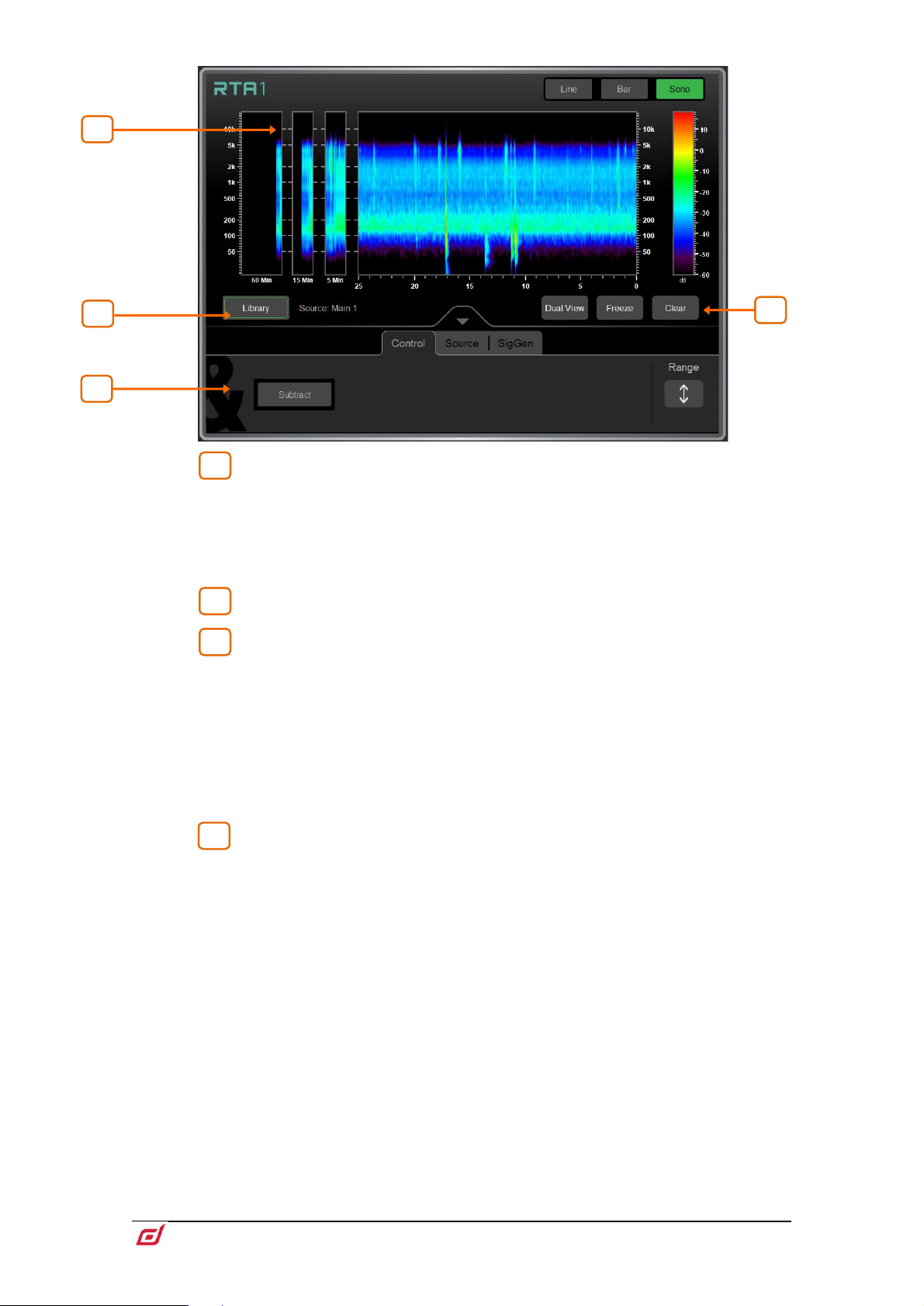
Sonogram – A 61 band Real Time Analyser or Sonogram is displayed here.
1
2
3
4
21 3
4
Select the view mode in the upper right corner.
In Sonogram mode, energy content over frequency is plotted over time and the dB
level colour coded. A 25s real time window is displayed as well as a 5min, 15min and
60min average. Sonogram is a useful tool to spot trouble frequencies, room
resonance or mix imbalance.
Library – Opens the RTA Libraries for storing and recalling RTA settings.
Sonogram Controls – Touch Subtract to display the difference between
RTA1 and RTA2. This can be useful when comparing two signals over time. Touch
Range and adjust the dB scale to the right of the graph to limit the area of focus of
the Sonogram.
In the Source tab, select the RTA Source. This can be locked to a specific channel,
set to External Control (for selection by another Surface, dLive Director or MixPad
app), or set to follow current channel selection. Enable PAFL Overrides Sel and
select the PAFL bus to have the RTA follow the PAFL source whenever PAFL is active.
The SigGen tab gives quick access to the Signal Generator Type, Level and Mute.
Dual View displays the RTA1 and RTA2 on the same screen, so that two signals
can be compared, for example a Mix channel and a measurement microphone.
Freeze holds a snapshot of the current measurement in place.
Clear clears the Sonogram.
Page 35
Firmware Reference Guide
35
V1.9
4. FX
1
2
3
4
5
2
5
3 4 1
5
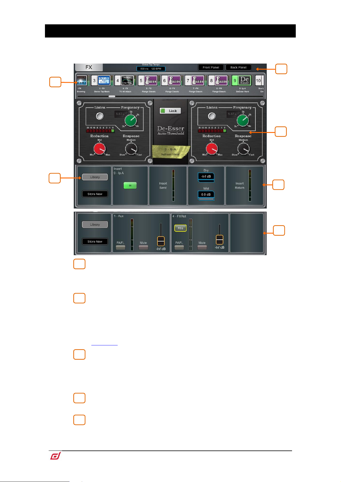
The FX screen gives access to the 16 virtual RackExtra FX engines.
FX bar – The 16 slots are shown across the top of the screen either empty or
with FX devices loaded. The FX name, current Library preset and metering is shown
next to each icon. Scroll left to right to view all the FX slots. Touch a device or empty
slot to select.
Library – Press the Library button or Lib key on the Surface to access the
FX Library. The Libraries are grouped by FX type. You can choose to load one of many
Factory presets, or to recall a previously stored User preset from the Show or directly
from your USB key. Touch to select a preset and touch Recall to load. Touch Store
New to store the current FX settings as a User preset. Touch Overwrite to update an
existing preset with current settings.
See Appendix A in this guide for more details on FX models.
Switch between the Front Panel and Back Panel view.
Tap on the Global Tap Tempo box or touch and use the screen rotary to set the
global rate for any delay FX locked to Global Tap Tempo. The current rate is shown.
The Tap Tempo can be assigned to a SoftKey using the Surface / Control / SoftKeys
screen.
Front Panel – All key FX controls are presented here. Switch to the Back
Panel to access routing settings.
Meters at the input and output of the currently selected FX are shown. If the FX
is inserted on a channel, the In switch and Dry/Wet level controls are shown. If the FX
is configured as a Mix->Return, then PAFL, Mute, and fader level are displayed for
both the send and return. Each FX Return has a 4-band parametric equaliser.
Page 36
Firmware Reference Guide
36
V1.9
Touch the PEQ switch to open the PEQ window.
The FX Front Panel, Library button and PEQ can also be accessed by the
Processing Screen when an FX Send or Return is selected, or by the Processing Insert
page when a channel with inserted FX is selected.
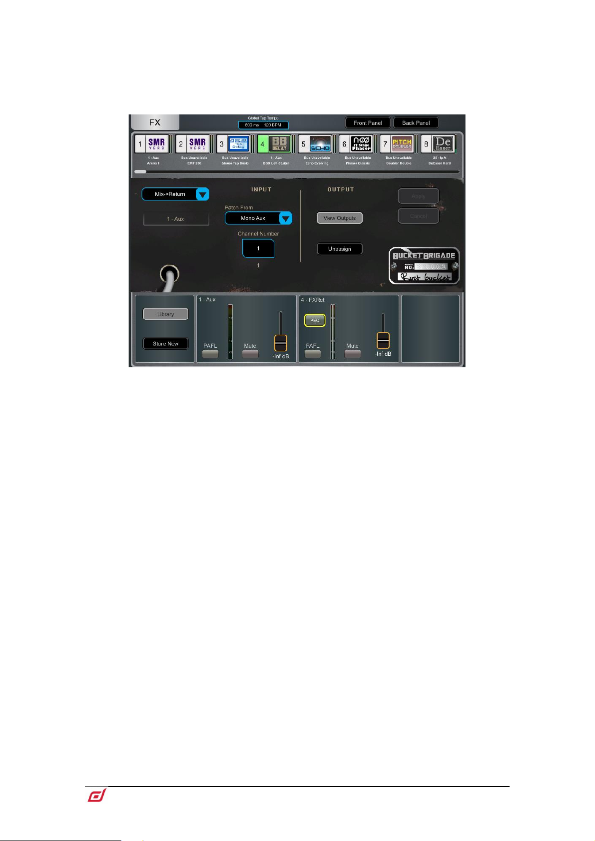
Back Panel – Use this view to edit the routing for the selected FX. Use the drop-
down box to choose between Unassigned, Insert or Mix->Return.
Insert breaks a channel signal path at its Insert point to route it to the FX and back
into the channel. Select the channel and press Apply to confirm. Some FX devices
allow a Dual Mono mode to insert the FX into two separate mono channels.
Mix->Return patches the FX device as a system effect with a Send bus and a
dedicated stereo FX Return channel. Select the bus you want the FX to use and press
Apply to confirm. The source patch defaults to the corresponding FX Send bus if
available in the current bus configuration. The output patch defaults to the dedicated
stereo FX Return channel. You can reassign an FX output to a different Input channel
using the Processing / Preamp screen of such channel.
Page 37
Firmware Reference Guide
37
V1.9
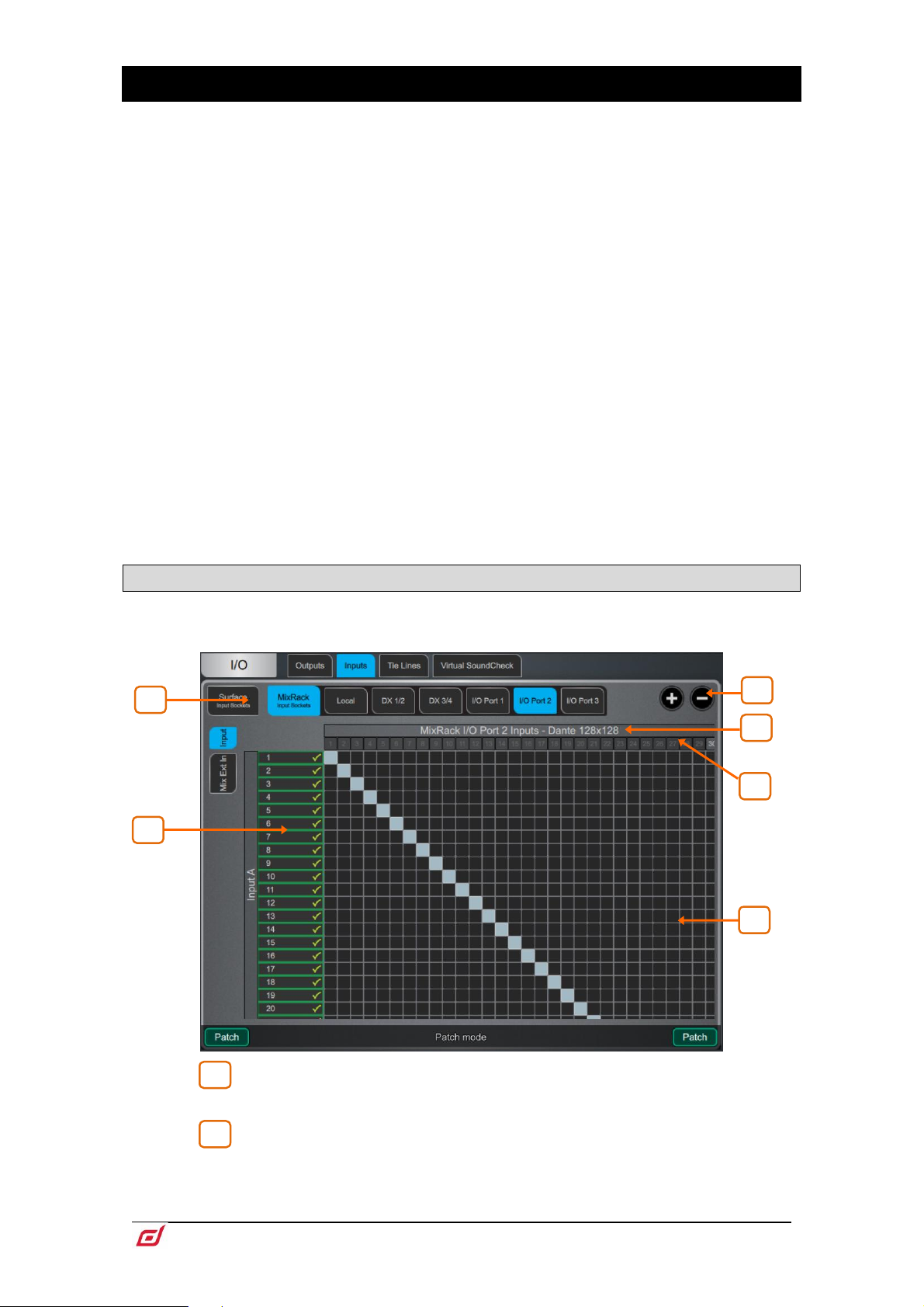
5. I/O
1
2 6 5
3 2 4
1
Use this screen to patch inputs and outputs from / to analogue sockets, I/O Ports, DX and DT Expanders,
USB, or to the ME monitor port. The patch is presented as a matrix view with solid cross-points indicating
an active connection. Striped cross-points indicate an invalid connection, for example when the output is
not available in the current system configuration.
⚙ Hold down Setup and touch anywhere in the I/O screen to access the following
preferences:
Confirm when reassigning opens a confirmation pop-up whenever a patch is being
changed.
Only patch when the Patch button is pressed requires a two fingers operation to
prevent accidental changes to the patch. Hold down the screen Patch button (Shift
key in Director) and touch a cross-point to patch when this option is enabled. Hold
down and draw a line on the matrix to quickly patch sources to destinations 1:1.
Use full screen takes advantage of the full touchscreen size when operating the I/O
screen.
Allow multiple tabs displays multiple items at the same time in the matrix view.
Library opens a Library of I/O patches with the option to recall Input, Insert and
Output Patchbay separately.
Custom Names renames I/O Port and DX tabs to a user specified name. Custom
names can also be toggled On or Off from this menu to display the original I/O Port
or DX socket number.
5.1 Inputs
Patch sources (displayed on top) to Input channels or to the Ext In of Mix channels (displayed on the left).
Navigation tabs – Touch on an item to present its associated sources or
channels to the matrix view.
Destinations – Input and Mix channel names and colours are displayed. A
green tick appears when any source is assigned to the channel. Touch a channel
name or number to edit its name and colour.
Page 38
Firmware Reference Guide
38
V1.9
Zoom – Use the two buttons provided or a two-fingers pinch in the screen
3
4
5
5
1
2
1
2
area to zoom in and out. Low levels of zoom provide a good overview of the I/O patch
but disable cross-point operation to prevent accidental changes.
I/O Card Names – When viewing an IO card tab, the IO card type is listed
here. The I/O card name can be swapped out for a custom name, from the Setup
menu.
Sources – The source number is greyed out if already patched, highlighted
in red if +48V is detected at the socket, or striped when the input is not available in
the current system configuration.
Touch on a socket number to open a window with a list of current assignments and
available controls for the socket, for example gain, +48V and Pad for a preamp, or
SRC options for a digital input.
When patching from a DT168 or DT164-W expander, preamp controls will appear
when a valid patch is made from a DT socket, via a Dante card, to the input channel.
Ensure the correct patch is made in both Dante Controller and the dLive’s I/O page.
Sample Rate Conversion can be bypassed for any stereo digital Input on a dLive
Surface or DX32.
Matrix view – With low levels of zoom, touch on an area of the matrix to
zoom in. With higher levels of zoom, touch on a cross-point to patch a source (Patch
button disabled). A confirmation popup will appear if the Confirm when reassigning
option is enabled. Touch on an active cross-point to unassign.
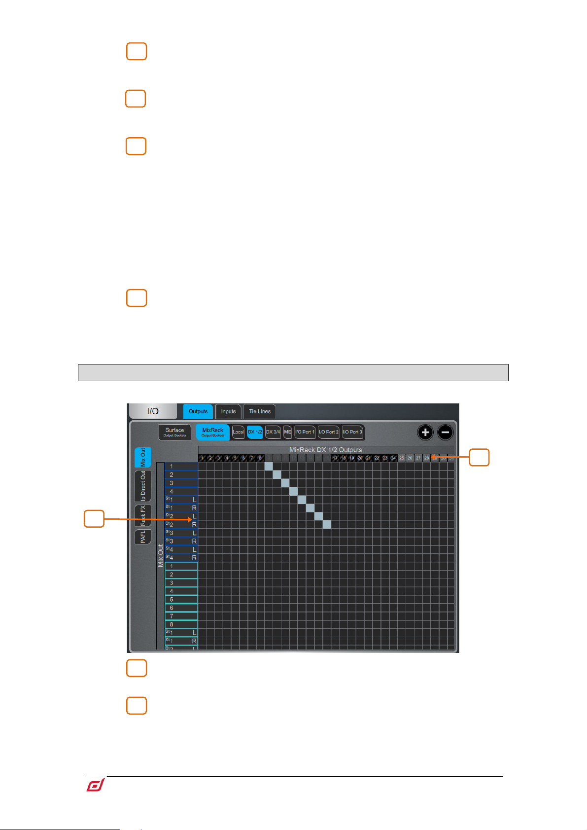
5.2 Outputs
Patch Mixes, Direct Outs, RackExtra FX or PAFL (displayed on the left) to outputs (displayed on top).
Sources – Channel names and colours are displayed. Touch a channel
name or number to edit its name and colour.
Destinations – The output number is greyed out if already in use, or striped
when the output is not available in the current system configuration.
Touch on a socket number to open a window with a list of current assignments and
available controls for the socket.
Page 39
Firmware Reference Guide
39
V1.9
For example, touch on a DX32 digital output to access its Polarity and Sample Rate
settings.
Touch on a ME output to access the Stereo Link option. When Stereo Linked,
outputs to the Allen & Heath Personal Monitoring System will be recognised as a
stereo pair and assigned to a single key on the ME-1 mixer.
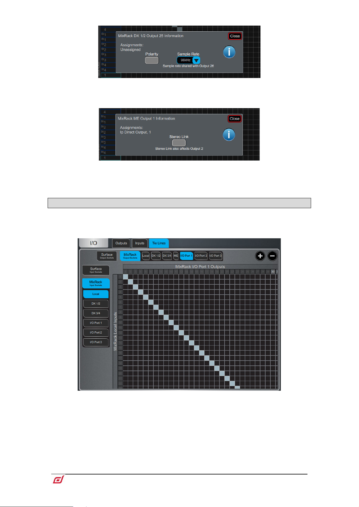
5.3 Tie Lines
Use this page to patch any source (displayed on the left) directly to one or multiple destinations (displayed
on top), without impacting on mix resources or bus configuration.
Digital Split using Tie Lines – In a digital split system (for example FoH and
Monitors), it is typical to use the Tie Lines to send the Local inputs from the Master
MixRack to an I/O Port and over to the Slave system, as pictured above. This method
(as opposed to using channel Direct Outs) splits the signals straight after the preamp
so they are unaffected by Digital Trim or Direct Out Source on the Master system.
Page 40
Firmware Reference Guide
40
V1.9
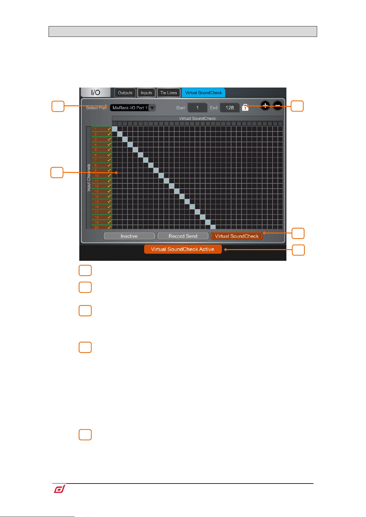
5.4 Virtual SoundCheck
1 2 3
4
5
4 5 2
3
1
Use this page to configure and enable Virtual SoundCheck. The Record Send and Virtual SoundCheck
modes are independent of Scene memories. This means you can patch analogue I/O, inserts and FX whilst
in Virtual SoundCheck, with the peace of mind that these changes will stay in place when you exit Virtual
SoundCheck. It also means that you can recall and store Scenes whilst in Virtual SoundCheck without the
need to use Safes or Recall Filters.
I/O Port – Select the I/O Port to use with Virtual SoundCheck.
Matrix View – Patch the channels to the I/O Port. It is typical to leave this
patch to 1:1 so that Inputs are straight from/to the same numbered I/O Port channel.
Range – You can limit the range of I/O Port channels dedicated to Virtual
SoundCheck. This can be useful if the same I/O Port is used for other applications at
the same time, for example for plugin processing or audio distribution. The range
selection is locked when in Record Send or Virtual SoundCheck mode.
Inactive disables Virtual SoundCheck. The normal I/O patch is in use.
Record Send sends the pre-trim audio from the Input Channels to the I/O Port for
multitrack recording purposes. This will temporarily override the normal output patch
to the selected I/O Port, if different.
The source point is always pre-trim (it doesn’t follow the Input Direct Out source
setting). For multitrack recording applications other than Virtual SoundCheck, where
the recording of the processed channel is required, go to I/O / Outputs and patch
Input Direct Outs instead.
Virtual SoundCheck sends audio from the I/O Port to the Input Channels in place
of the live inputs, temporarily overriding the normal input patch.
Virtual SoundCheck Active – A message is displayed on screen to
remind the user that Virtual SoundCheck is active. Touch the orange box in any other
screen to go back to this screen.
A Virtual SoundCheck button will also appear in the
This allows you to disable Virtual SoundCheck on individual channels, for example to
run a live mic alongside the recorded tracks.
Processing / Preamp screen.
Page 41
Firmware Reference Guide
41
V1.9
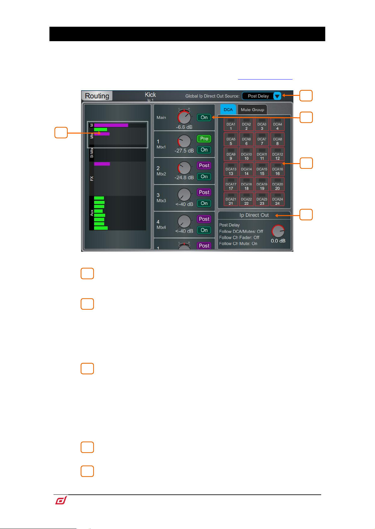
6. Routing
1
2
3
4
5
4
3
1 5 2
The Routing screen lets you view and adjust sends, routing and assignments for the currently selected
channel. It offers an alternative to using the dLive fader strips, Mix keys and Assign / Pre keys.
For more information on using the fader strips on the Surface please refer to the
dLive Surface Getting Started Guide available for download at www.allen-heath.com.
Input channels – Displays routing, assignments and Direct Out controls.
Sends are shown as a purple bar if post-fade, as a green bar if pre-fade. The
bar is filled in if the channel is assigned to the Mix, the outline only is shown otherwise.
Group assignments are shown as a purple dot.
Touch the drop-down menu to select the Global Direct Output Source. This
setting affects all channel Direct Outputs and can be set to Post Preamp, Post LPF,
Post Gate, Post Insert A Return, Post PEQ, Post Compressor, Post Insert B Return,
Post Delay.
⚙ Hold down Setup and touch anywhere in the Routing screen to access further
options for the Direct Out including Follow Fader, Follow Mute and Follow All
(DCA/Mutes, Ch Fader/Mute)
Scroll in this area or scroll / touch anywhere in the overview area to navigate
the controls. Touch On/Off to toggle the channel assignment to the Main Mix, FX
send, Aux, or Group. Touch Pre/Post to switch the FX or Aux send pre-fade or postfade. Touch on a rotary control and use the screen rotary to adjust the send level or
channel level to the Main mix. Touch on a Pan control and use the screen rotary to
adjust the send Pan (stereo sends and Main mix only).
In 5.1 Main mode, a surround panning icon is displayed instead of the Pan control.
Touch this icon to access surround panning and LFE level (see below).
In LCR+ Main mode, touch the Pan control to access LCR+ settings.
DCA & Mute Group assignments – Touch the On/Off buttons to
toggle the channel assignment to the associated DCA or Mute Group.
Direct Out – Touch the control and use the screen rotary to adjust the Direct
Out level. The current source point for the Direct Out is displayed in addition to
whether the Direct Out is configured to follow DCA or Channel Faders and Mutes.
Page 42

Firmware Reference Guide
42
V1.9
Touch the text area to open the Direct Out options including Follow Fader, Follow
1
2
3
4
5
1
5
4
2 3 1
4 2 1
Mute and Follow All (DCA/Mutes, Ch Fader/Mute)
Surround panning – Access to 5.1 image, options and LFE level.
Panning mode – Touch the drop-down menu to select the panning mode
for the selected channel with regards to the front triplet.
LR – The Pan control will affect the stereo image to L and R. No signal will be sent to
C.
LCR – Each channel can be panned from left, through centre to right. At mid pan, full
signal is fed to C and none to L and R. Stereo Inputs and FX Returns will be hard
panned to LR.
LCR+ – The Pan control will affect the stereo image while the Divergence control will
determine the amount of signal to C vs LR.
Level – This is the Main channel level.
5.0 Panning – Drag the red pointer to position the channel at any point in
the 5.0 image.
Divergence – When the Panning Mode is set to LCR+, this control
determines the amount of signal to C vs LR, given a fixed stereo image. For example,
at mid pan and with the control fully clockwise (full Divergence), no signal is fed to C
and the stereo image relies on LR only (the so called ‘phantom centre’). At mid pan
and with the control fully anti-clockwise (no Divergence), the signal is sent to C only.
LFE and Non-LFE levels – Use the LFE level to control the amount of
signal sent to the Main LFE channel. Use the Non-LFE level to control the amount of
signal sent to the Main 5.0 mix. This is always open by default but can be attenuated
up to –inf for example for use with special LFE-only effects.
Surround panning – Access to 5.1 image, options and LFE level.
Panning mode – Touch the drop-down menu to select the panning mode
for the selected channel. See above in the Surround Panning paragraph.
Page 43

Firmware Reference Guide
43
V1.9
Level and Pan – This is the Main channel level.
2
3
4
1
2 3 4
4 3 1
2
5.0 Panning – Drag the red pointer to position the channel at any point in
the 5.0 image.
Divergence – When the Panning Mode is set to LCR+, this control
determines the amount of signal to C vs LR, given a fixed stereo image. For example,
at mid pan and with the control fully clockwise (full Divergence), no signal is fed to C
and the stereo image relies on LR only (the so called ‘phantom centre’). At mid pan
and with the control fully anti-clockwise (no Divergence), the signal is sent to C only.
Aux, Main, Matrix and FX sends – Displays routing and assignments of Input
channels, FX Returns and Groups to the selected Mix, as well as DCA and Mute Group
assignments for the selected Mix.
Mix Source – The point within the channel signal path that feeds the
selected Mix is set globally for each Mix using this drop-down menu. It can be set to
Post Preamp, Post Insert A Return, Post PEQ, or Post Delay.
Sends overview – Sends from Inputs, FX Returns and Groups are shown
as a purple bar if post-fade, as a green bar if pre-fade. The bar is filled in if the channel
is assigned to the Mix, the outline only is shown otherwise. Use the tabs on top to
display Inputs, FX Returns or Groups.
Routing controls – Scroll in this area or touch in the overview area to
navigate the controls. Touch On/Off to toggle the channel assignment to the Mix.
Touch Pre/Post to switch the channel send pre-fade or post-fade. Touch on a rotary
control and use the screen rotary to adjust the channel send level. Touch on a Pan
control and use the screen rotary to adjust the channel send Pan (stereo sends only).
Follow Main Pan – Touch this button to open the Follow Main Pan Settings.
Page 44

Firmware Reference Guide
44
V1.9
1
2
2
1
Follow / Invert – Each stereo mix can have its own settings. When Follow
is enabled, any changes to channel pans to the Mains (i.e. LR) will be followed by the
send pans. When Invert is enabled, channel Main pans will be inverted to the stereo
mix. If Follow and Invert are both enabled then channel Main pan settings will be
followed and inverted to the stereo mix. Touch Apply to confirm changes or Discard
to cancel changes.
Set All – Quickly enable or disable Follow and/or Invert on all stereo mixes.
Touch Apply to confirm changes or Discard to cancel changes.
DCA and Groups – Displays channel assignments to the DCA or Group. Touch
On/Off to toggle the channel assignment to the DCA or Group. Use the tabs on top
to display different channel types.
⚙ Hold down Setup and touch anywhere in the Routing screen to access the DCA
fader to 0dB option. This forces the DCA level at 0dB.
Page 45

Firmware Reference Guide
45
V1.9
7. Scenes
1
2
5
3
2
6
4
1
Use this screen to work with the dLive Scene memories. Up to 500 Scenes may be stored, and one or more
Cue Lists can be created from the Scenes. Global Scene Safes and per Scene Recall Filters can be set to
block certain parameters from recall.
7.1 Scene Manager
Gives access to the Scene list for editing or recalling.
Scene list – Choose to display the list of all 500 Scenes or the Current Cue
List. The Scene highlighted in yellow is the currently selected Scene, and is displayed
in the top left corner of the System screen. The Scene highlighted in green is the Next
or ‘Go’ Scene, and is displayed in the top right corner of the System screen.
Swipe up/down or use the screen rotary to scroll, and touch in the list to select a
Scene. Both the yellow and green indicators will move to confirm the selection. Note
that the Next (green) Scene can be selected independently from the Current Scene
using the Surface Prev and Next keys.
Icons in the Scene list indicate the following:
A Scene is stored in this memory location.
This is the last recalled Scene, and is also displayed in the Home screen and
under the Scene list.
Embedded Recall is set for this Scene.
A Crossfade Time is set for this Scene.
Recall Filters are set for this Scene.
The Scene is locked.
When more than one Surface or Director instance is connected to the system and
Surface Roles are in use, the yellow scene selector and last recalled scene icon are
Surface/Director specific.
Name Touch the Name box to open the keypad and type in a name up to 14
characters long for the currently selected Scene. Touch the Description box to enter
a note about the Scene.
Page 46

Firmware Reference Guide
46
V1.9
Crossfade Time Touch the Crossfade Time and use the screen rotary to
3
4
5
6
set a crossfade time up to 20 seconds for the currently selected Scene. This time sets
how long it takes for levels and pan to change from their current settings to the settings
of the Scene being recalled. Crossfades affect Input faders and Pan, Mix faders, DCA
faders, send levels and Pan.
When a scene with a Crossfade Time is recalled, the scene name will show a progress
bar for the duration of the crossfade.
Crossfades affect the audio levels, however the faders on the Surface will move
instantly to their new position. Manually moving a fader during a crossfade will
overwrite the crossfade for the associated channel.
Recall – Touch Go or press the Surface Go key to recall the Next (green)
Scene. This overwrites current settings with those stored in the Scene being recalled.
Touch Undo Go or hold down the Reset key and press the Go key on the Surface to
restore the settings prior to a Scene recall.
In a Multi-Surface system, Undo Go is Surface specific
Modify – All these functions affect the currently selected (yellow) Scene.
Touch Store or press the Surface Store key to store current parameters to the Scene.
To undo a Store Scene, press and hold the Surface Reset button and the Surface or
TouchScreen Store button simultaneously.
Store Scene Undo will undo the last store on the Surface or Director session it is
triggered from. It will not undo a Store Scene made by another Surface/Director
session.
Press the Surface New key to store current parameters to the next available (empty)
memory location.
You can update only a selection of parameters to the current Scene or a range of
Scenes. Touch Update to open the Update Scene Range window (see below).
Touch Delete to clear the name, content and Recall Filter of the Scene.
Touch Recall Filter to view and edit the Recall Filter settings for the Scene (see
below).
Touch the Lock button to lock the Scene from any edit thus preventing accidental
changes.
Touch Copy Filter To… to copy the current recall filter settings to either a single
scene, a range of scenes or all scenes.
You can automate the recall of one or more other Scenes from the same or a different
unit when you recall a Scene. Touch Embedded Recall to open the Embedded Recall
settings for the Scene (see below).
Custom MIDI strings can be broadcast over TCP/IP when recalling Scenes. Touch
Custom MIDI to enter the MIDI string in hexadecimal format. A custom MIDI string
associated with a Scene is sent on recall in addition to the standard MIDI string as
defined in the dLive MIDI TCP/IP Protocol document.
Touch Copy to copy the content and Recall Filter of the currently selected
(yellow) Scene. Touch the Scene you wish to copy to and touch the Paste button to
paste. Scene names and descriptions are not copied.
⚙ Hold down Setup and touch anywhere in the Scene Manager screen to access
several Scene management preferences:
Scene Overwrite Confirmation displays a confirmation pop-up on Scene Store and
when using the Scene Manager page. A confirmation pop-up is always displayed on
Scene Delete.
Scene Recall Confirmation displays a confirmation pop-up on Scene Recall. A
confirmation pop-up is always displayed on Scene Delete.
Page 47

Firmware Reference Guide
47
V1.9
Display Last Recalled displays the Last Recalled Scene in blue in the top left corner
of the screen, instead of the currently Selected Scene.
Disable Surface Controls locks the Scene area of controls on the dLive Surface, to
prevent accidental operation.f
Auto Store automatically stores current settings to the last recalled Scene whenever
a Scene is recalled. It is typically used during soundcheck to save all changes to a
Scene before recalling a different one.
Auto Store affects the last recalled Scene as displayed in the Home screen, this is
not necessarily the currently selected (yellow) Scene.
In a Multi-Surface system, Auto Store is Surface specific
Track Embedded moves the Current (yellow) pointer to the last recalled Scene when
Embedded Recalls are set.
Auto Increment moves the Next (green) pointer to the next available Scene in the list
whenever a Scene is recalled, so that the Next Scene is always the Current Scene +
1. It allows recalling multiple sequential Scenes quickly with a single button press.
Go on Touch lets you recall a Scene simply by touching its location in the Scene list
and Scene widget. The currently selected Scene is highlighted in orange in this mode.
No confirmation pop-up is displayed when Go on Touch is active. Only use this
option if really required.
MixRack Startup Scene lets you specify a Scene which will be recalled every time
the MixRack boots up, for example for automatic reset in a fixed installation setting.
7.2 Recall Filters
A Recall Filter prevents certain channels or parameters being overwritten by the Scene recall. It
only affects the Scene it is associated with.
Use the tabs on the left to view the different parameter groups. Pinch/unpinch to zoom
in and out of the matrix view. Swipe up/down or left/right to navigate through the
matrix. Touch an item to toggle. Allowed items will be recalled, Blocked items will not.
Touch a parameter label on top of the table to toggle one parameter for all channels.
Touch a channel label on left to toggle all parameters for one channel. Touch All to
toggle all items in the current tab, or touch Block All or Allow All to affect all items in
all tabs.
Scene recall filters can be copied and pasted from the Scene Manager window –
see Section 7.1 for details
Page 48
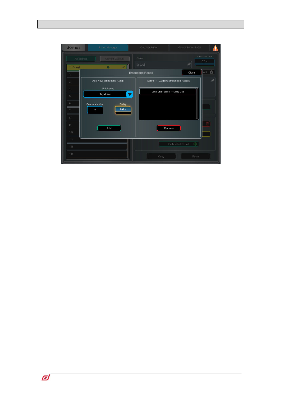
Firmware Reference Guide
48
V1.9
7.3 Embedded Recall
You can automate the recall of one or more other Scenes from the same or a different unit when
you recall a Scene. A delay time can be set for each embedded Scene within the host Scene.
Select the target unit or system from the Unit Name drop-down. All compatible Allen
& Heath units found on the dLive network are listed here. Select ‘My dLive’ to automate
Scenes on the local system.
Set the Scene Number to select the Scene you wish to embed. Its name is displayed
below the box. Set the Delay time for the embedded Scene recall. This is the time the
system waits before recalling the Scene after you have recalled the host Scene. Time
can be set from 0 sec (instant) to 4 minutes. Touch Add to add the Scene to the list
on the right.
The list shows the embedded Scenes together with associated units and delay times.
Select one and touch Remove to remove from the list.
Page 49
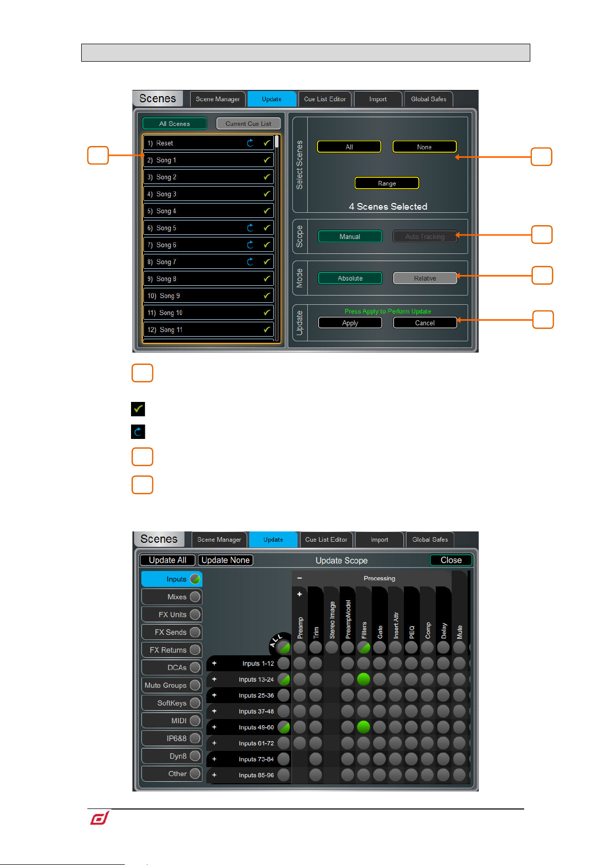
Firmware Reference Guide
49
V1.9
7.4 Update
1
2
3
3
5
4
1
2
Update parameters in one or multiple scenes.
Scene List – Touch to select the Scene(s) to be included in the update. Any
number and combination of Scenes can be selected from this list.
A Scene is stored in this memory location.
This scene will be included in the update – touch to toggle.
Select Scenes – Quick options to select All, None or a Range of scenes.
Scope – Select one of the following options:
Manual – Touch to open the Update Scope matrix and manually select which
parameters to include in the update.
Page 50

Firmware Reference Guide
50
V1.9
Use the tabs on the left to view the different parameter groups. Pinch/unpinch to zoom
4
5
in and out of the matrix view. Swipe up/down or left/right to navigate through the
matrix. Touch an item to toggle. Items highlighted in green will be updated, all other
items will be ignored. Touch the + and – symbols to show and hide nested
parameters.
Touch a parameter label on top of the table to toggle one parameter for all channels.
Touch a channel label on left to toggle all parameters for one channel. Touch Update
All to select all items, or touch Update None to deselect all items.
Auto Tracking – This option tracks all parameter changes made by the user. After
making the desired changes to parameters you can Apply these changes to the
selected scene(s).
This pop-up indicates the system is in Auto Tracking
mode and parameter changes are being recorded. Touch
the pop-up at any time to return to the Update page and
Apply or Cancel the changes
Mode – Select the update mode:
Absolute - Overwrites the target parameters in the selected scene(s) with the current
values.
Use Absolute mode to change a parameter in multiple scenes to a fixed value
Example: Change IP1 fader level to 0dB in all scenes.
Relative - Changes to level parameters (Gain/Fader/Send/Master) are applied
relatively to the selected parameters in the target scene(s).
Use Relative mode to change a parameter in multiple scenes by a fixed value
Example: Increase IP1 fader level by +3dB in all scenes.
Non-level parameter changes in Relative mode will be applied Absolutely to the
target scene(s).
When performing a Manual-Relative update, only parameters that have changed
since the last scene recall will be applied to the target scene(s).
Update – Select Apply to update the selected parameter(s) in the target
Scene(s). Press Cancel to discard the update.
Page 51
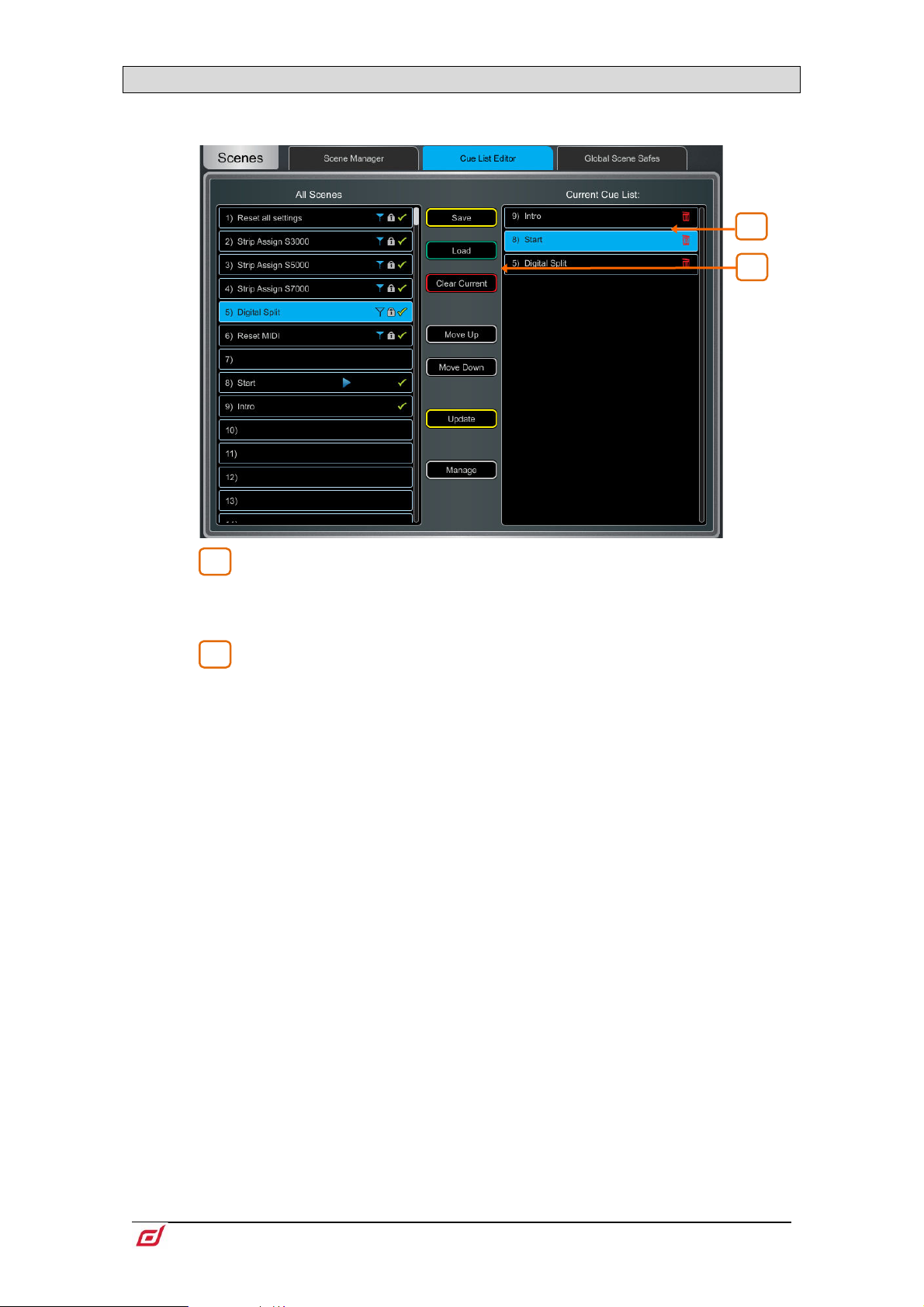
Firmware Reference Guide
51
V1.9
7.5 Cue List Editor
1
2
2
1
A Cue List is a custom list of Scenes selected from the list of available Scenes. Cue Lists can be named,
saved, recalled and deleted.
Current Cue List – Drag and drop Scenes here to create a Cue List.
Scenes can be placed in any order and repeated any number of times in the list. To
remove a Scene from the Cue List, touch the trash can icon to the right of the Scene
name.
Touch Save to name and store the current Cue List. Touch Load to select and
open a previously saved Cue List. Touch Clear Current and confirm to remove all
Scenes from the current Cue List.
Touch Move Up or Move Down to move the selected Scene in the current Cue List.
Touch Overwrite and confirm to update a saved list with the current Cue List. Touch
Manage to open a list of saved Cue Lists and delete one or more.
Page 52
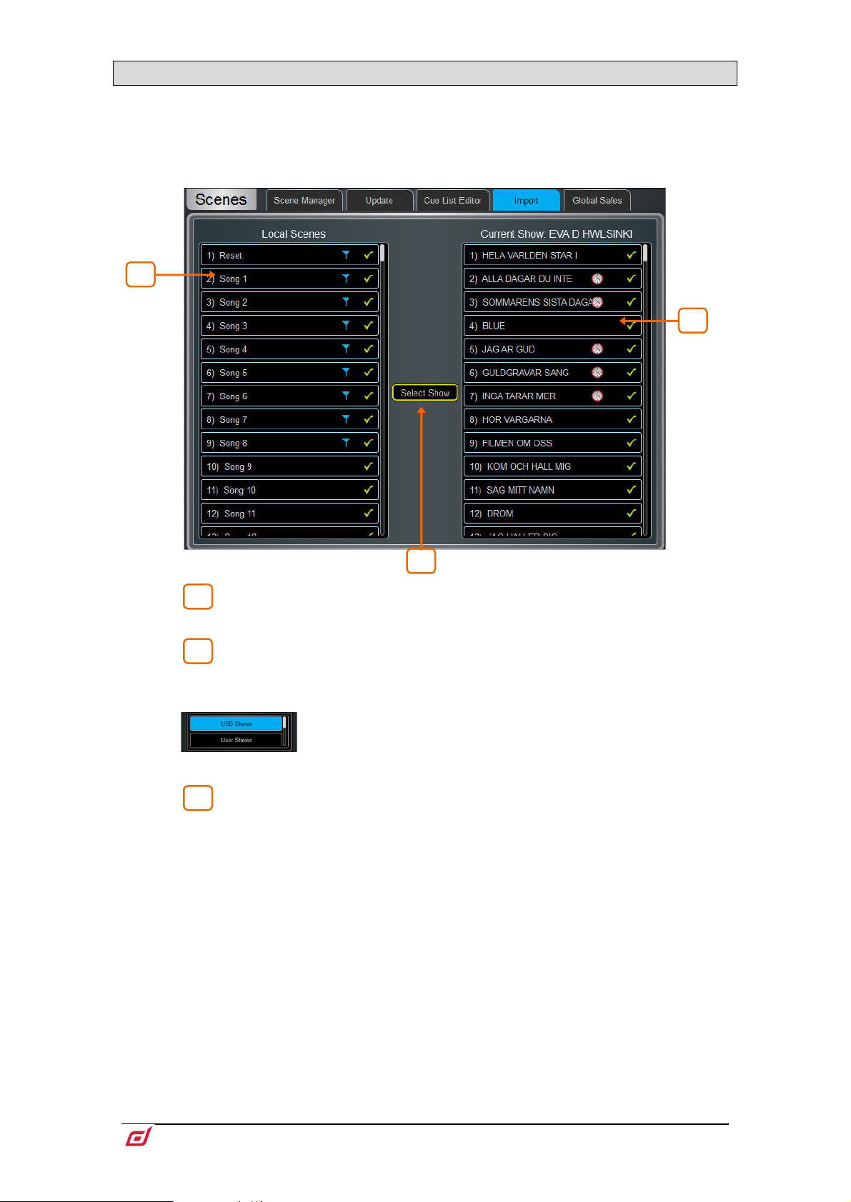
Firmware Reference Guide
52
V1.9
7.6 Scene Import
1
2
3
2
3
1
Scene Import allows the user to import one or more Scenes from an existing Show into the
current Show. This might be useful for example in festival situations where Scenes from a guest
engineer’s Show are imported into the current Show - without any audio interruption - and then
filtered as required.
Local Scenes – A list of scenes in the currently loaded Show. Swipe to
scroll through the list.
Select Show – Touch to select the Show that contains the scene(s) you
wish to import.
Click on the dropdown menu to toggle between Show
locations – USB or User.
Selected Show – A list of scenes in the show you wish to import from. Drag
and drop scenes from this column into the Local Scenes column to import them into
your show.
Page 53
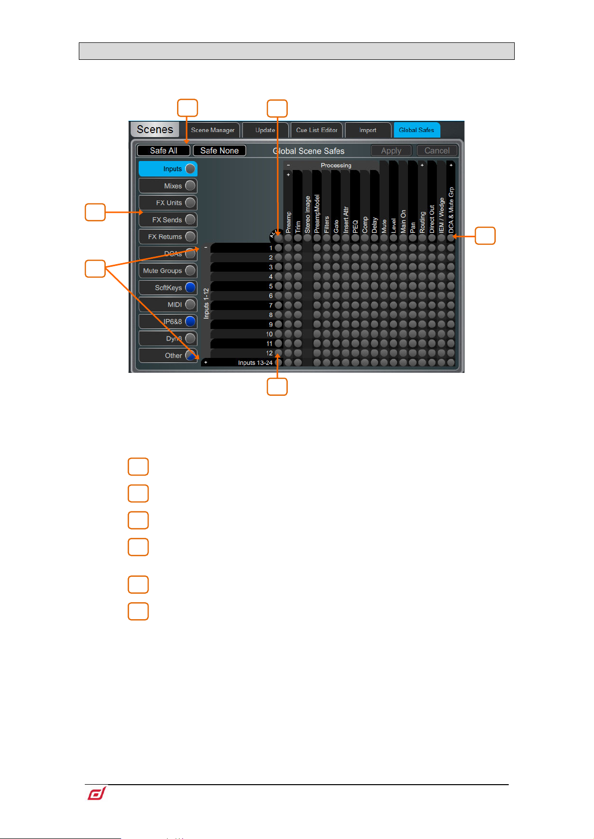
Firmware Reference Guide
53
V1.9
7.7 Global Scene Safes
1
2 3 4
5
6
6
5
4
3
2
1
Scene Safes prevent certain channels or parameters being overwritten by a Scene recall. Contrary to the
Recall Filters, this setting is global, affecting ANY Scene recall. It is typical for certain settings such as
SoftKeys assignments to be made Safe so their settings are global within the Show.
Pinch/unpinch to zoom in and out of the matrix view. Swipe up/down or left/right to
navigate through the table. Touch an item to toggle its state.
Safe items (highlighted in blue) will not be recalled.
Use the tabs on the left to view the different parameter groups.
Touch the + and – symbols to show and hide nested parameters.
Touch a channel label on left to toggle all parameters for one channel.
Touch a parameter label on top of the table to toggle one parameter for all
channels.
Touch All to toggle all items in the current tab,
Safe All or Safe None to affect all items in all tabs.
A blue dot lights in a screen tab when one or more items have been safed in that tab.
Page 54
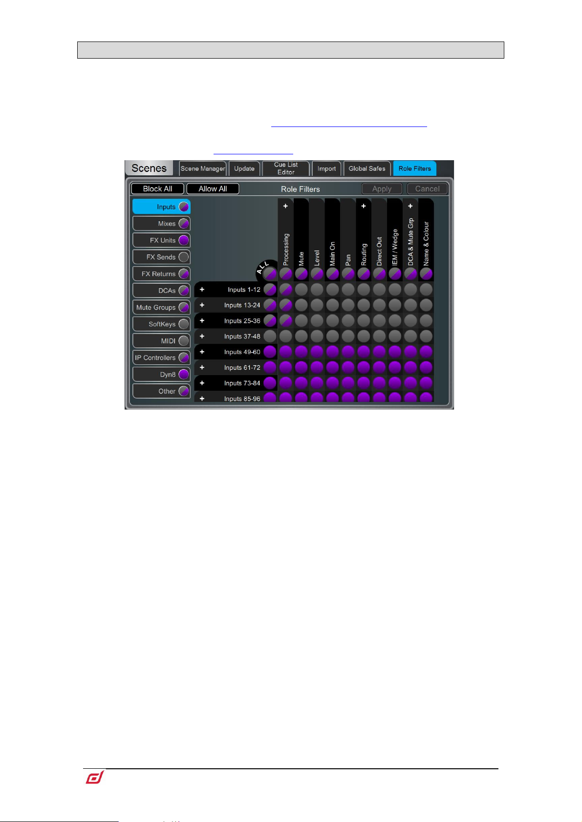
Firmware Reference Guide
54
V1.9
7.8 Role Filters
A Role Filter prevents certain channels or parameters being overwritten by any Scene recall. It only affects
the Role it is associated with, so that channels, mixes, FX and other settings used by another engineer are
not affected by Scene recall on the local Surface. It is typical to set opposite Role Filters on two Surfaces in
Multi-Surface mode. For example, if Inputs 1-64 are used at FoH, they would be blocked on the Role Filters
for the Monitor Surface, and Inputs 65-128 would be blocked by the Role Filters on the FoH Surface. The
same would apply to all other settings. See the
this configuration.
See the section on Surface Preferences for information on creating Roles
Multi-Surface FOH/MON template show for an example of
Use the tabs on the left to view the different parameter groups. Pinch/unpinch to zoom
in and out of the matrix view. Swipe up/down or left/right to navigate through the
matrix. Touch an item to toggle. Allowed items will be recalled, Blocked items will not.
Touch a parameter label on top of the table to toggle one parameter for all channels.
Touch a channel label on left to toggle all parameters for one channel. Touch All to
toggle all items in the current tab, or touch Block All or Allow All to affect all items in
all tabs.
Note that multiple Surfaces and Director instances on the same MixRack will
always share the MixRack settings, including processing and mixing. In a MultiSurface setup, make sure the Role Filters are set such that settings are split between
the Surfaces. This avoids accidental recall of settings affecting channels or mixes
operated by the remote Surface(s).
Page 55
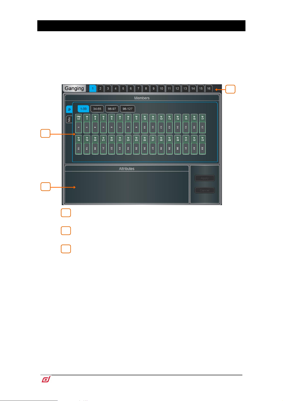
Firmware Reference Guide
55
V1.9
8. Ganging
1
2
3
3
1
2
Use this screen to create and edit up to 16 Gang groups. A Gang links all or a selection of processing and
routing parameters for two or more channels or mixes of the same type. The channels or mixes in a Gang
are known as ‘Members’. The parameters are known as ‘Attributes’.
Ganging provides absolute, not relative control.
Gang settings follow Scene automation. You can ‘safe’ Gang settings from being
overwritten using the Scenes / Global Scene Safes page.
Touch one of the 16 Gang tabs at the top of the screen to create or edit a Gang
group. A Gang with channels already assigned highlights yellow.
Members – Select either the Input (Ip) or Mix tab. Touch the channels you
wish to gang or ungang. A channel or Mix can only belong to one Gang.
Attributes – Touch the parameters you wish to link. Adding the Routing
attribute links the sends and assignments from the ganged channels. Touch Apply to
confirm the changes.
Preamp Gain cannot be ganged. You can set Gain controls to a nominal level, then
gang the Trim controls and use to make input level adjustments while mixing.
Alternatively, configure a Stereo Input in MixRack / Config / IP Stereo Config to
permanently link two Input channels and their preamps within the current Show.
Page 56
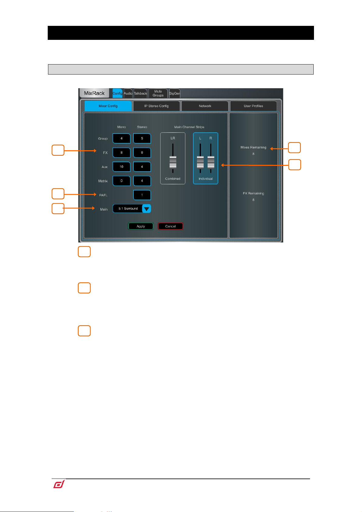
Firmware Reference Guide
56
V1.9
9. MixRack Setup
1 2 3
2
3
5 4 1
These pages give access to the mixer bus configuration, Input stereo configuration, network settings, audio
settings and User Profiles.
9.1 Config / Mixer Config
Use this page to reconfigure the architecture of the 64 Mix busses available.
Bus configuration – Touch a box and use the screen rotary to set the
number of mono / stereo Groups, FX sends, Aux sends and Matrix outputs. You can
choose any combination, but note that mono busses can only be added / removed in
pairs.
PAFL – Touch and use the screen rotary to set the number of stereo PAFL
busses. Set to 1 for a typical standalone system. Extra PAFL busses can be useful
when multiple operators are sharing the same dLive system. For example, an engineer
mixing FoH on the Surface, and a second engineer mixing Monitors on a laptop or
additional Surface.
Main – Select one of 5 modes of Main mix:
None - No Main mix, for example dedicated monitor mixing with a large number of
Aux mixes.
LR - Standard stereo Main mix.
LR+Msum - A stereo Main mix with additional output which is the mono sum of the
pre-fade, pre-processed LR mix. For example to feed a mono delay speaker or zone.
LR+M - A 3-way main mix with independent stereo LR and mono M busses. Channels
can be separately assigned to any combination of LR and M. Typical application for
M is main centre speaker, mono PA or bus-fed sub bass.
LCR – A 3-way main mix with LCR panning. Each channel can be panned from left,
through centre to right. At mid pan, full signal is fed to M and none to L and R. Stereo
channels feed the LR mix only.
LCR+ - A 3-way LCR main mix with two controls to position the sound. Pan balances
between L and R, and Divergence blends the signal between C and LR.
5.1 Surround – Multichannel 5.1 output. Each channel can be set to LR, LCR or LCR+
panning with regards to the front triplet. When in this mode, an on-screen surround
panning widget is displayed in the Routing screen.
Page 57
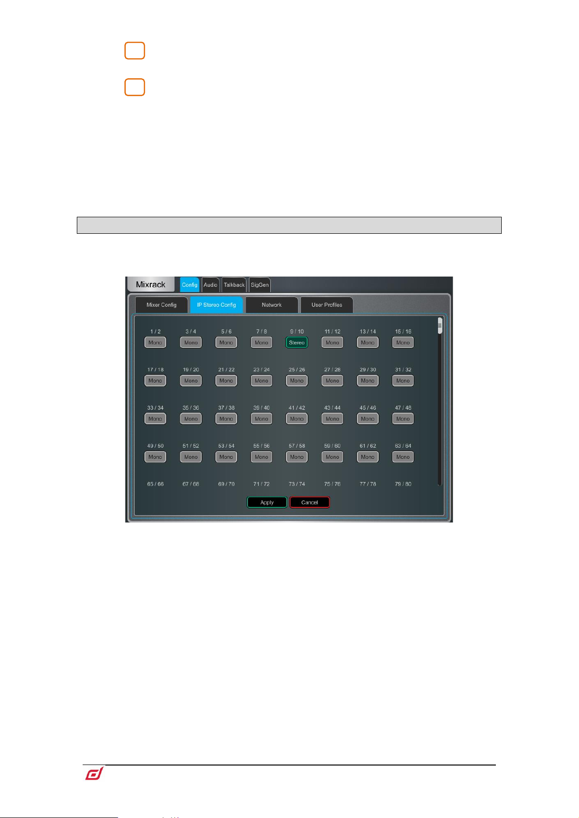
Firmware Reference Guide
57
V1.9
Displays the number of busses and FX sends remaining and warns if you
4
5
exceed the maximum.
Main Fader Strips – The Main LR mix can be presented on the Surface as
a single, Combined fader strip or as two Individual fader strips. When ganged, all
processing for LR including delays is linked. A Balance control is provided to adjust
the relative Left and Right level. The option will also affect the Main surround channels
sL and sR.
Press Apply to confirm the changes. All current settings other than the bus
configuration will stay in place.
Mix Config reassigns the bus architecture and resets mix parameters. These
changes if needed should be done before, not during a show.
9.2 Config / IP Stereo Config
Displays the current mono/stereo configuration of the 128 Input channels. Stereo channels are highlighted
in green. Touch the buttons to change the configuration and press Apply to confirm. Stereo channels use
a single fader strip and all their processing controls are linked.
This is intended for permanently configuring channels as stereo inputs, for
example music players. Use the
sources while mixing live.
Ganging screen for on-the-fly linking of stereo
Page 58

Firmware Reference Guide
58
V1.9
9.3 Config / Name & Colour
1
2
3
3
2
1
Use this page to change or reset the name and colour of a range of channels. Name and colour for
individual channels can be edited from the Processing Screen.
Channel Selection - Set the channel Type from the drop-down menu.
Touch Select All or set the Start and End to select a range of channels.
Name – Press Reset to restore the default channel names to the selected
range. Touch the name box to edit the name when a single channel is selected.
Colour – Touch a colour to change or press Reset to restore the default
channel colours to the selected range.
Page 59

Firmware Reference Guide
59
V1.9
9.4 Config / Network
1
2
3
1 3 2
Use this page to configure the IP Address and Unit Name to identify the MixRack on the network.
IP Settings – To set a static IP Address, touch the IP Address box and type
in the address. Make sure the Subnet Mask and Gateway are valid, and all devices on
the network including Wi-Fi routers, access points or laptops have unique but
compatible addresses.
The default MixRack IP Address is 192.168.1.70 with Subnet Mask 255.255.255.0 and
Gateway 192.168.1.254. You can restore these defaults by touching the Reset button.
Enable DHCP to allocate an IP Address to the MixRack by a network DHCP server,
for example a Wi-Fi router.
Only use DHCP when a DHCP server is connected to the MixRack. If DHCP is
enabled and the MixRack is powered up while no server is present, it can take longer
than usual for the system to boot.
Unit Name – A name with up to 16 characters can be set to identify the
MixRack on the network. The default is ‘dLive Mix Rack’.
Connections – Displays the number of active network connections to the
MixRack. The Surface and touchscreens count as one connection each.
Page 60

Firmware Reference Guide
60
V1.9
9.5 Config / User Profiles
1
2
2
1
Up to 10 User Profiles including an Administrator can be set to restrict operator access and protect selected
functions.
Users – The Admin user has access to all functions and can set permissions
and allocate passwords if required for the other users. The password, if one is set, is
required when the User logs in, changes User or locks / unlocks the dLive Surface.
Icons in the list indicate if a password is set and if the User is active.
Touch a User to edit its profile. Touch Active to enable this User in the
Login screen.
Home / User
Settings – Touch the User Name box to enter a name up to 16 characters.
Touch the Password box to set or change a password up to 16 characters. Touch the
Comment box to enter an additional note.
Touch the User Scene drop-down to select a Scene to recall automatically when the
User logs in. This will overwrite current settings. A User Scene can ensure that the
mixer is restored to a known starting point for the User.
The User Scene only recalls when the User is changed. It does not recall when the
same User logs in or the system is powered up without changing User.
Press Set Permissions to open the Permissions window (see below).
User Profiles are stored in the dLive MixRack. They are not stored in Show
memories.
dLive MixPad sessions will follow the User Permissions of the User logged in on
the iPad.
Page 61

Firmware Reference Guide
61
V1.9
User permissions – Each User can have their own set of Permissions applied.
Use the tabs across the top of the window to view and set different groups of
permissions. Select an item in the list and toggle the Enabled/Disabled button as
required. The window on the right provides a description of the functions included in
the currently selected item. Use the Enable All / Disable All buttons to quickly toggle
all items in the currently open tab. Touch Apply to accept the changes.
Page 62

Firmware Reference Guide
62
V1.9
1 2 3 4 5
2
1
9.6 Config / RF Devices
Use this screen to monitor and configure up to 45 connected receivers.
Firmware 1.70 and higher support Shure ULX-D, QLX-D and Axient Digital devices.
Firmware 1.90 and higher support Sennheiser 2000, 2050 and 300, 500 (G3/G4)
devices.
External RF Device Channels – Information on node and device name,
receiver channel, socket association and Online/Offline status. Touch to select a
device.
Add Sennheiser Device – Press to add a Sennheiser receiver to the RF
devices list, and type the IP address of the receiver.
Page 63

Firmware Reference Guide
63
V1.9
Associate with Socket – Associate the selected RF device channel with
3
4
5
a MixRack, Surface, DX, DT or I/O Port socket. This step is required for
appear in the Preamp section of Input channels.
RF Info to
Enable / Disable Detection – When no devices are connected it is
recommended to Disable Detection to minimise network traffic. This can be done for
Shure and Sennheiser independently.
A MixRack power-cycle is required when disabling Shure detection.
Clear Offline Devices removes offline RF receivers from the RF Devices list.
Unassign All Offline removes all socket associations for offline RF Devices.
Unassign All removes all socket associations for both online and offline RF Devices.
9.7 Audio / I/O Port
These tabs display information on the fitted card in I/O Port 1, 2 and 3, and give access to any relevant
option.
See Appendix D for module specific information.
Note that clock, redundancy and other options for the Dante, Waves and
EtherSound cards are accessed by the Audinate, Waves Audio or Auvitran software
respectively. Access to these settings is not provided by the dLive interface.
Page 64
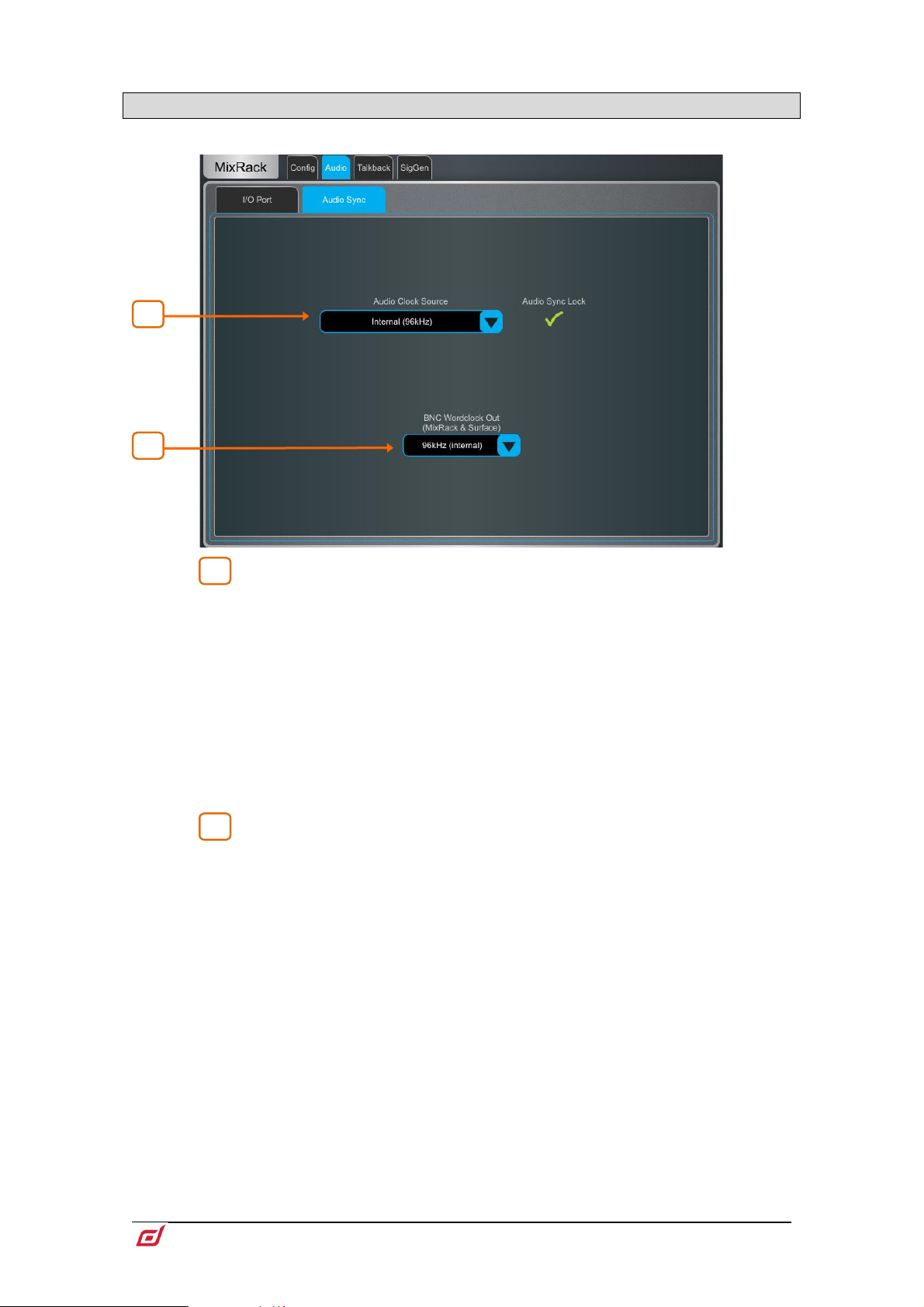
Firmware Reference Guide
64
V1.9
1
2
1
2
9.8 Audio / Audio Sync
Use the Audio Sync page to set the audio clock options for the system.
Audio Clock Source – Select the clock source for the dLive system. Set
to Internal (96kHz) to use the internal audio clock, this is the default setting. Set to
an I/O Port to sync from an audio networking card, or MixRack / Surface BNC
Wordclock In to sync from a 96kHz Wordclock provided at the BNC input of the
MixRack or Surface.
When linking two or multiple systems together using audio networking cards, the
‘Master’ system (typically the one that has control over the preamps) is set to Internal
and all other systems are set to sync from the relevant I/O Port.
Only sync from 96kHz sources or, if an M-DL-ADAPT ‘letter-box’ adapter is fitted,
from a 48kHz audio networking card fitted in the adapter.
When using a dLive C Class MixRack, an option is displayed in this page to set the
BNC connector as either a Wordclock input or output.
BNC Wordclock Out – Select the sample rate for the Wordclock output
provided at the Surface and MixRack. This can be set to Off, 44.1kHz, 48kHz or
96kHz (internal).
Page 65
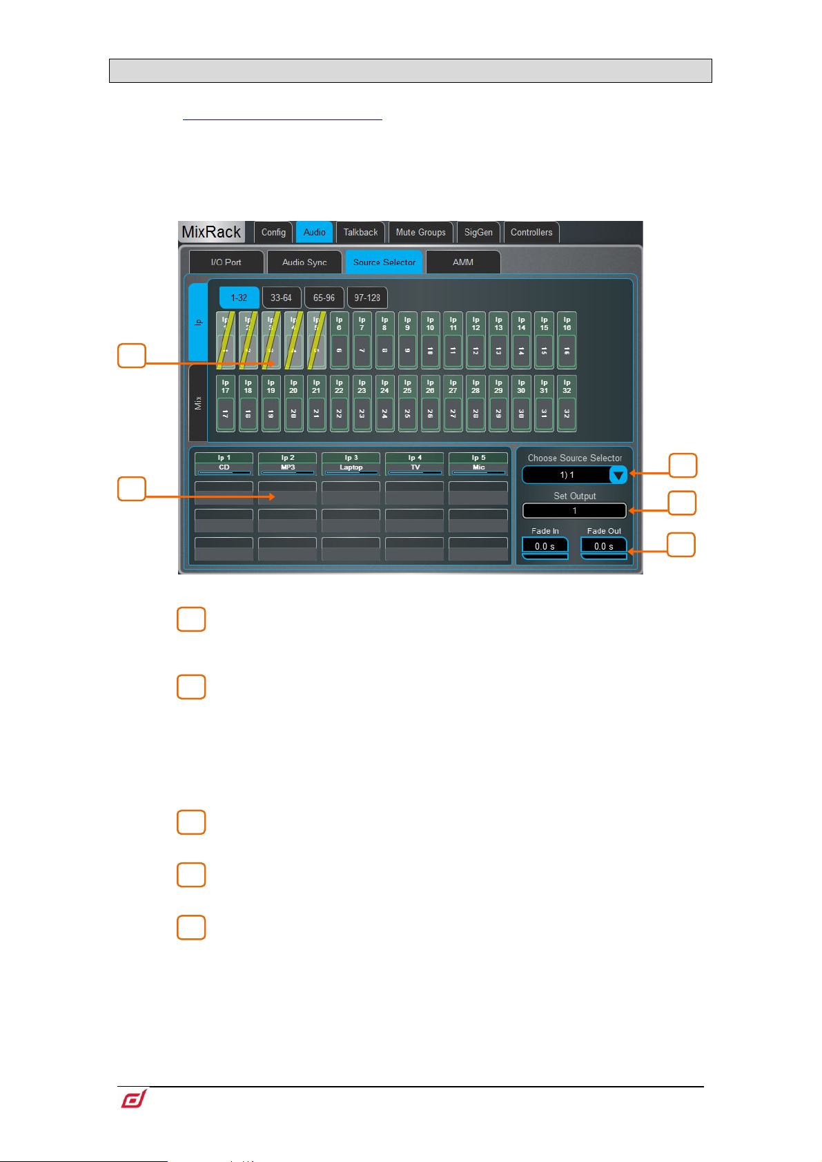
Firmware Reference Guide
65
V1.9
9.9 Audio / Source Select
1
2
3
4
5
3
4 5 2
1
The Source Select page allows the configuration of up to 20 Source Selectors, each with up to 20 sources,
that can be
Sources configured in a Source Selector are mutually exclusive on the output Mix. This can be used for
example for selection of background music in a room, with automatic crossfades when switching sources.
Note that any Input or Group routed to the selected output Mix but not selected as a member will not
be affected by the Source Selector. This allows for a priority mic, paging, announcement or alarm system
to be always routed to the output Mix regardless of the active source in the Source Selector.
controlled via IP Remote Controllers.
Sources: Inputs / Mixes – Use the vertical tabs to switch between inputs
and mix busses (Grp, Aux. Mains) Drag and drop inputs and/or groups into the lower
pane to add them to a Source Select group.
Source selector members – This area shows the members of the
currently selected Source Select group along with the current level. Each group can
contain up to 20 sources which can be any combination of inputs and groups.
Once a source has been added to the group, touch the source to specify the name,
colour and on-level for the source. The name and colour specified for a source here
is independent from the name and colour used for the source elsewhere in the system
so you can give “friendly” labels to the sources for the operators.
Source Selector – Touch to select a Source Select group. Up to 20 Source
Select groups can configured.
Output – Touch to select a stereo or mono Aux or Matrix that is used as the
output for the source select group.
Fade In/Out Time – Set Fade In and Fade Out times between sources of
up to 10s.
Page 66
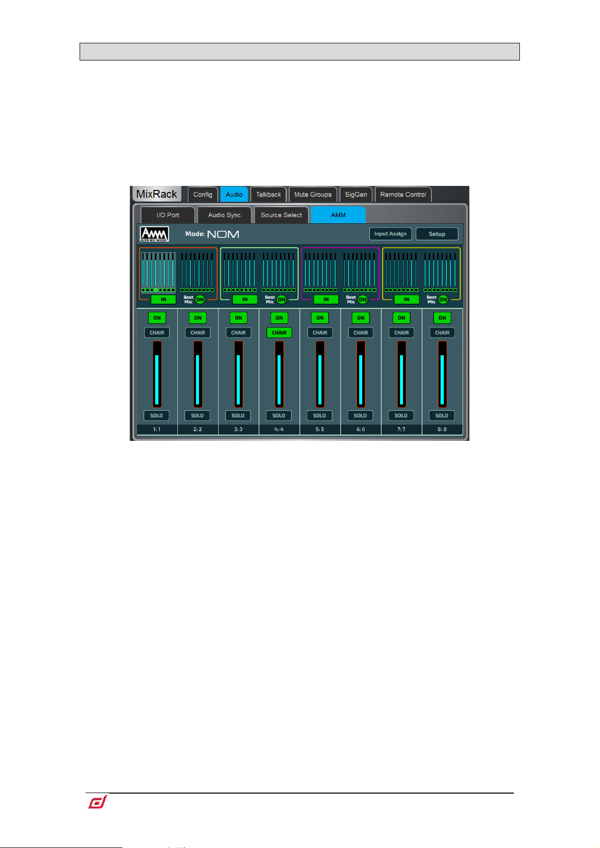
Firmware Reference Guide
66
V1.9
9.10 Audio / AMM
The Automatic Mic Mixer (AMM) provides automatic level control of multiple microphones for spoken word
applications such as conferences and discussion panels involving several participants each with their own
mic around a table. This improves intelligibility and can reduce the risk of feedback by reducing the levels
of mics which are not being spoken into. Once set, the AMM needs little or no change at all whilst still
allowing the engineer to maintain absolute control of the mix.
The AMM is intended for speech applications, not music.
Main Screen - NOM Mode
ON - When switched to 'ON' the AMM takes automatic control using its own gain
element just after each fader.
Chair - You can set a channel as 'Chair' to give it higher priority over the other
channels, for example to let a chairman override another speaker. The Chair mic
sensitivity and the amount that other channels are automatically ducked when the
Chair is open can be set.
Best Mic - This option ensures a single participant activates the one microphone
receiving the strongest signal. This can prevent crosstalk, phasing and ambience
issues caused by multiple microphones triggering for the same voice. The Chair mic
is not part of the Best Mic On calculation.
We recommend you only select Best Mic On if all microphones involved are the
same type and have similar positioning and gain.
Solo - Each input has a solo option which opens the selected channel and turns all
others down. This is not additive. Only one channel can be soloed at a time.
Page 67
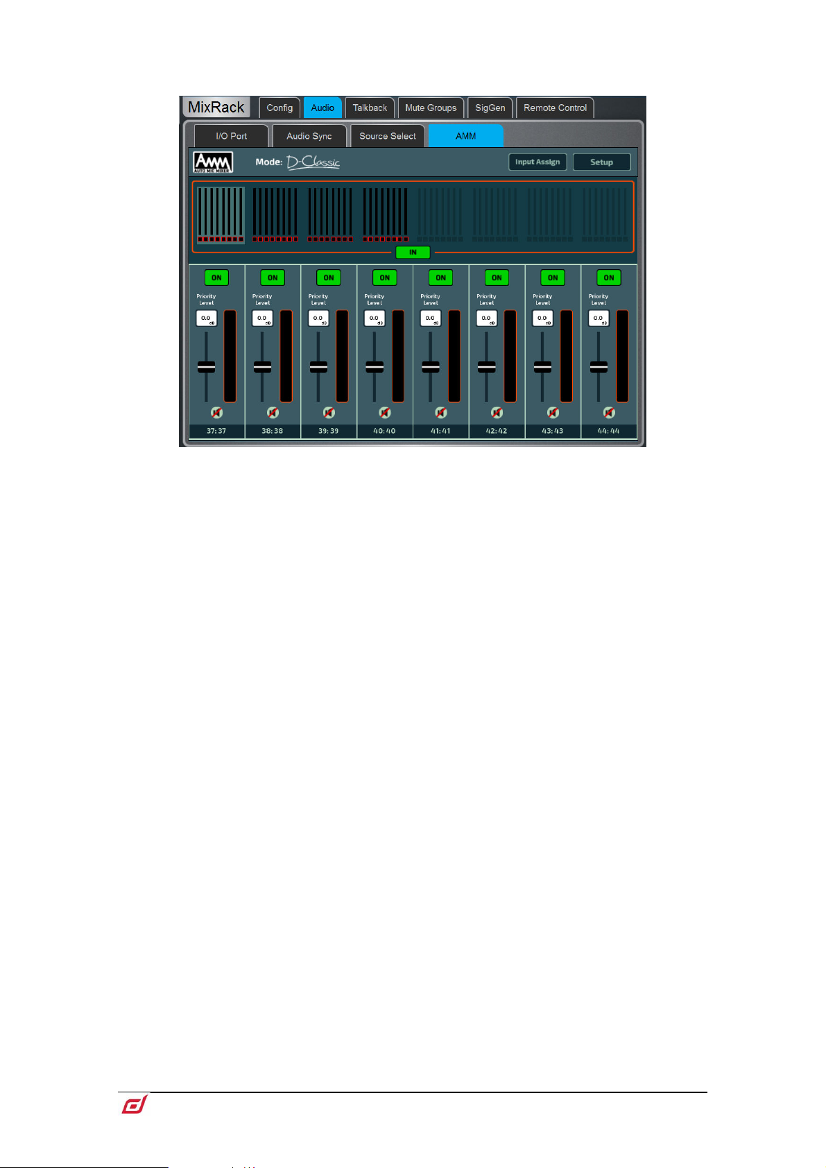
Firmware Reference Guide
67
V1.9
Main Screen - D-Classic Mode
Unlike NOM mode which uses gating and fixed gain attenuation, D-Classic uses a
'constant gain sharing' algorithm to dynamically adjust the gain for each mic
proportional to its input level. Louder signals will receive more gain in the mix.
Priority Level - For each channel you can set a priority 'level' which will offset the
amount of gain going into the mix calculation and therefore give a higher or lower
artificial gain to that channel. This is a variable slider with a range from -15dB (low
priority) through 0dB (no offset) in the middle to +15dB (high priority) at the top.
ON - When switched to 'ON' the AMM takes automatic control using its own gain
element just after each fader.
D-Classic does not provide Best Mic On, Solo, Chair or other setup functions.
Page 68
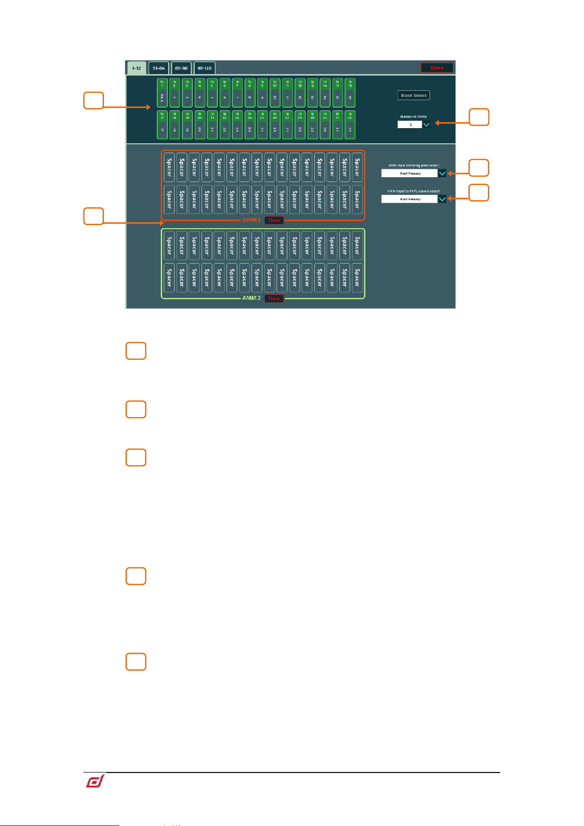
Firmware Reference Guide
68
V1.9
Input Assign
1
2
3
4
5
5
4 3 2
1
The Input Assign window is used to specify the number of AMMs and the members of
each AMM.
Inputs – Drag and drop inputs from this area into the desired AMM. All 128
inputs can be accessed, in blocks of 32, via the tabs above the input strips. Turn on
Block Select and touch the first and last item you wish to assign to drag a range of
channels into the lower window.
AMM(s) – Here you can view the members of each active AMM. To remove
an input from an AMM, drag and drop the item to the upper pane. A Clear button is
provided to quickly remove all inputs from an AMM.
Number of AMMs – Choose between 1, 2 and 4 AMM zones:
1 AMM = Maximum 64 members
2 AMM = Maximum 32 members per AMM
4 AMM = Maximum 16 members per AMM
When working with multiple AMMs in NOM mode, each AMM has its own Chair, Best
Mic and Solo options.
Settings in the Setup screen, including AMM mode, are applied to all active AMM
zones.
AMM Input metering-point select – Select the metering point for
Inputs assigned to the AMM:
Post Preamp
Post Gate/PEQ
Post Compressor (Pre AMM)
Post Delay (Post AMM)
AMM Input to PAFL source select – Select the PAFL source point
for Inputs assigned to the AMM:
Post Preamp
Post Ins A Ret
Post PEQ (Pre AMM)
Post Delay (Post AMM)
Page 69
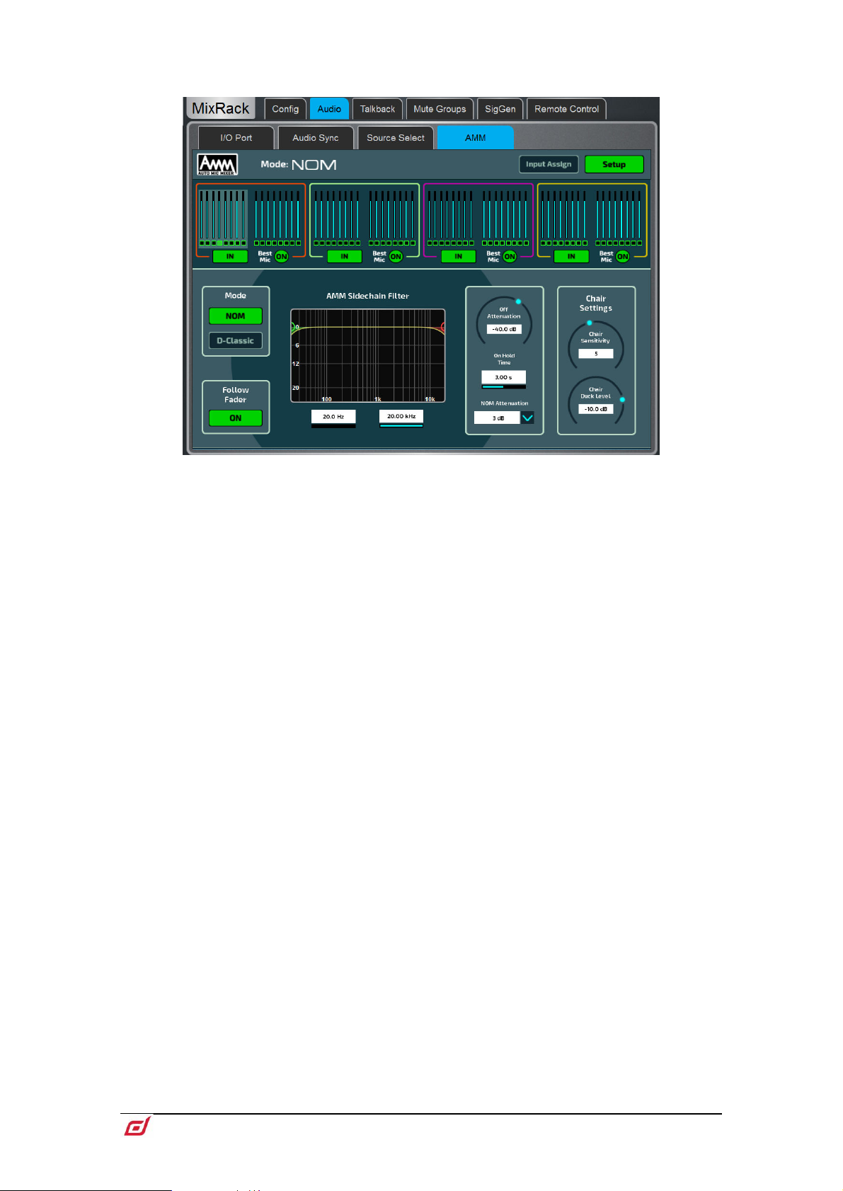
Firmware Reference Guide
69
V1.9
Setup: NOM
Side Chain Filter - Set High Pass and Low Pass filters to cut off frequencies below
and above the normal speech range that may cause false triggering of the mics.
Off Attenuation - Set the amount of shutoff for closed mics (from -10dB to -90dB).
On Hold Time - Set the amount of time an open mic is held open once the trigger is
removed (from 1 to 5 seconds). The Chair mic is not affected by Hold Time.
NOM Attenuation - Set the amount of attenuation applied per doubling of open mics
(from 3 to 6dB).
Chair Sensitivity - Set the sensitivity of signal required to trigger a Chair mic open
and therefore duck the other mics (from 1 to 10 = least to most sensitive).
Chair Duck Level - Set the amount of attenuation applied to other mics when a Chair
mic is open (from -3 to -40dB).
Page 70
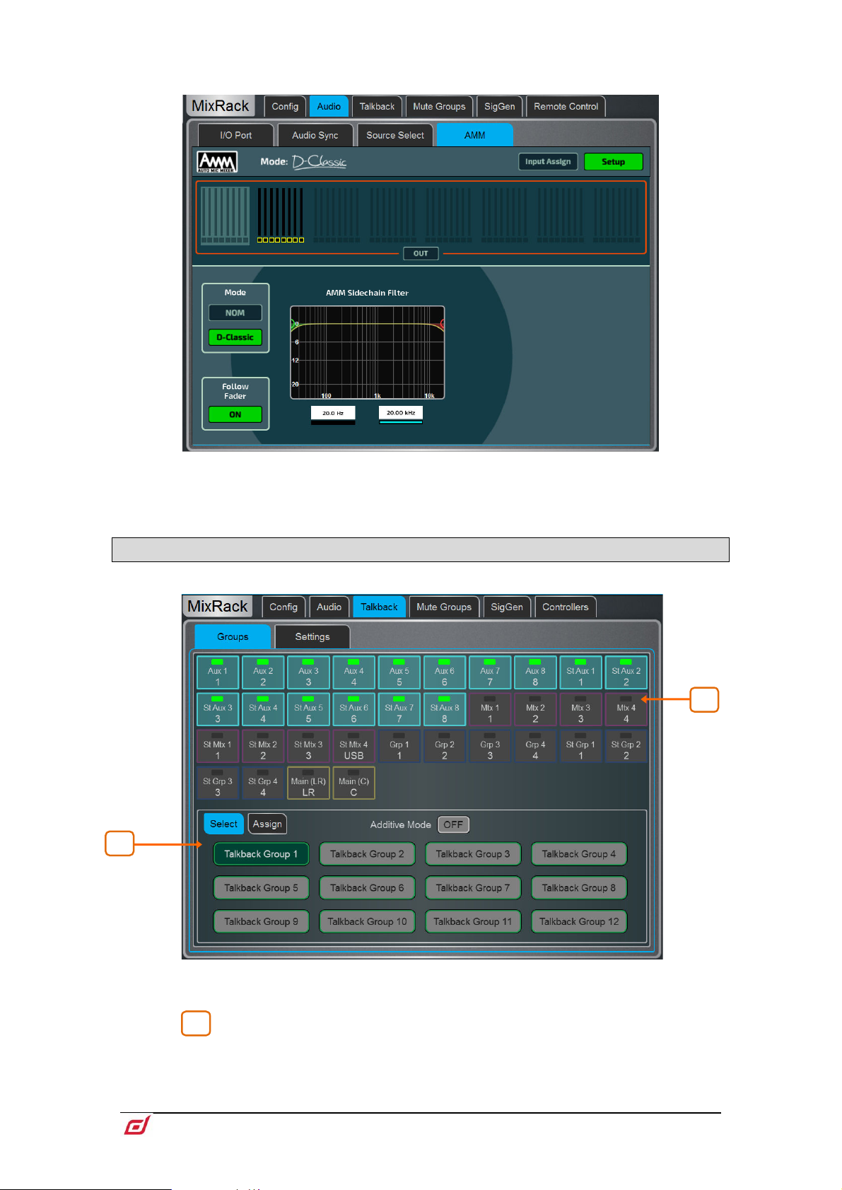
Firmware Reference Guide
70
V1.9
Setup: D-Classic
1
2
1
Side Chain Filter - Set High Pass and Low Pass filters to cut off frequencies below
and above the normal speech range that may cause false triggering of the mics.
9.11 Talkback
Use this screen to assign and configure Talkback.
Groups – Use this page to choose Talkback destinations and assign them to the
twelve Talkback Groups.
Use the Select tab to activate Talkback Groups. Enable Additive Mode to
allow multiple Talkback Groups to be activated at one time.
Use the Assign tab to select a Talkback Group, assign destinations and edit the
Talkback Group name and colour. Available destinations include Aux, Mtx, Grp and
Page 71
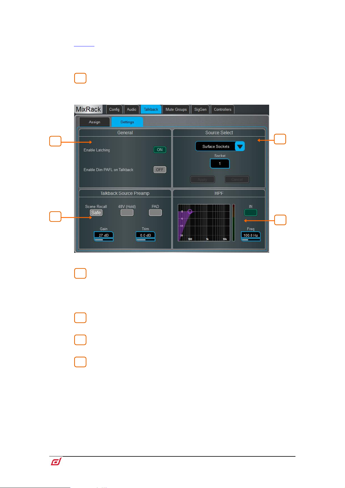
Firmware Reference Guide
71
V1.9
Main mixes. A destination can be selected in more than one Talkback Group and
2
1
2
3
4
4
2
3
1
multiple destinations can be selected within a Talkback Group.
SoftKeys on the Surface, Director and IP Controllers can configured to select a
Talkback Group with either momentary or latching action.
Pressing the physical Talkback Assign button on the Surface, or the virtual Talkback
Assign button in Director, will also open this screen.
Mixes – Whilst in the Assign tab, with a Talkback Group selected, touch a
Mix button to assign Talkback to that destination.
Settings – Use this page to choose the Talkback source and set its options.
General – The default Talk switch operation is momentary (press and hold
while talking). Turn on Enable Latching for latching operation (press to turn on, press
again to turn off).
Enable Dim PAFL on Talkback attenuates the PAFL signal while talking to prevent
feedback from the engineer’s monitor into the Talkback microphone.
Talkback Source Select – Use the drop-down menu and Socket box to
select the Talkback source from any system input. Press Apply to confirm.
Talkback Source Preamp – Set the source Gain, Trim, Pad and phantom
power. You can also make the source Safe from Scene recall.
HPF – High Pass Filter frequency and In/Out switch.
Page 72
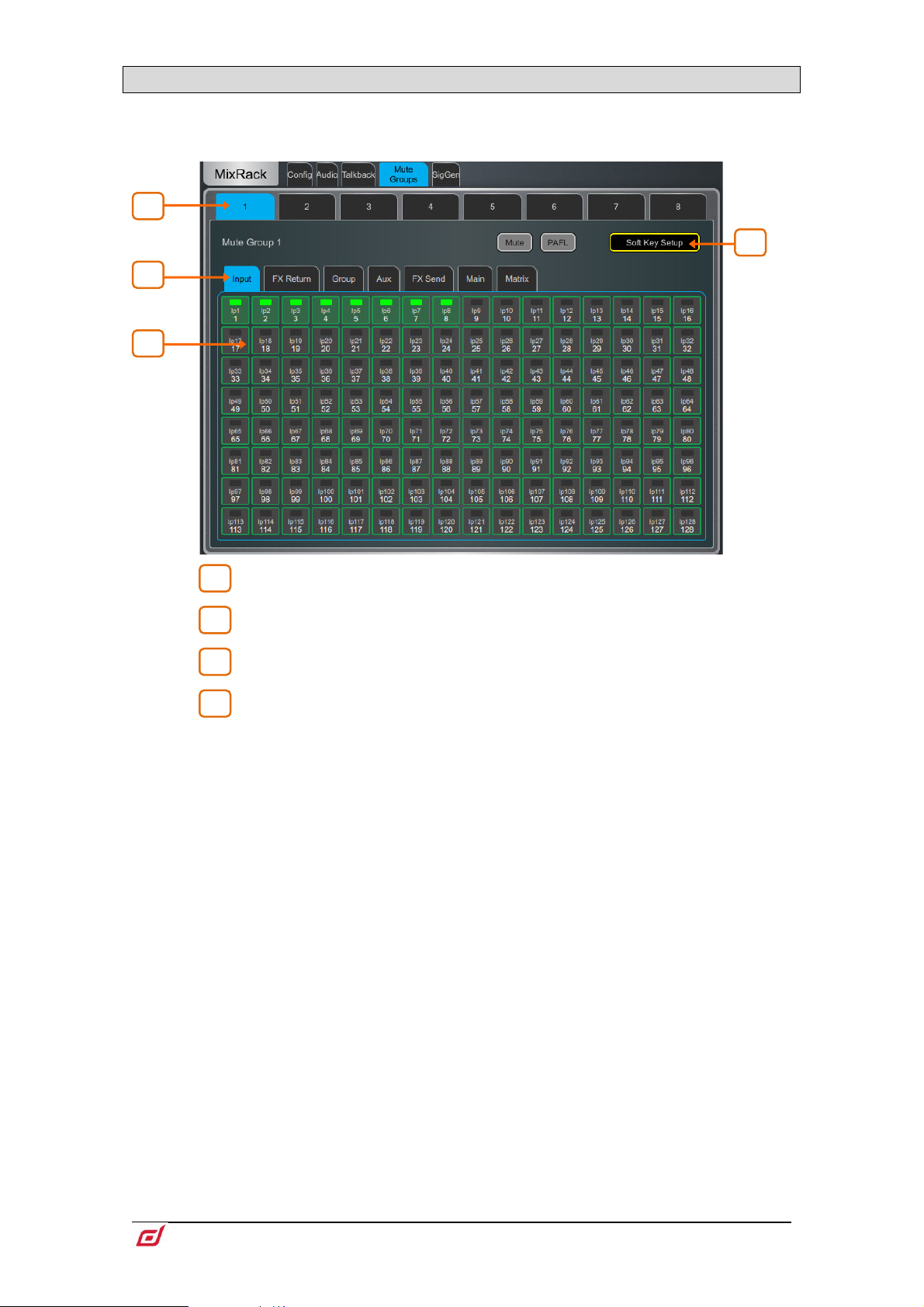
Firmware Reference Guide
72
V1.9
9.12 Mute Groups
1
2
3
4
2
3 4 1
dLive provides 8 Mute Groups in addition to the 24 DCA Groups. This page lets you assign channels and
mixes to Mute Groups and control Mute masters. You can assign one or more SoftKeys to control the Mute
Groups using the
Surface / Control / SoftKeys menu.
Select the Mute Group using the tabs at the top of the page.
These tabs let you navigate all available Input channels, FX Returns and Mixes.
Touch the on/off buttons to toggle the channel assignments to the Mute Group.
Touch Mute to mute the Mute Group. Touch PAFL to listen to the contribution
of the channels assigned to the Mute Group in the Monitor system. Touch SoftKey
Setup to open the
Mute Group to a SoftKey.
Surface / Control / SoftKeys menu should you wish to assign the
Page 73
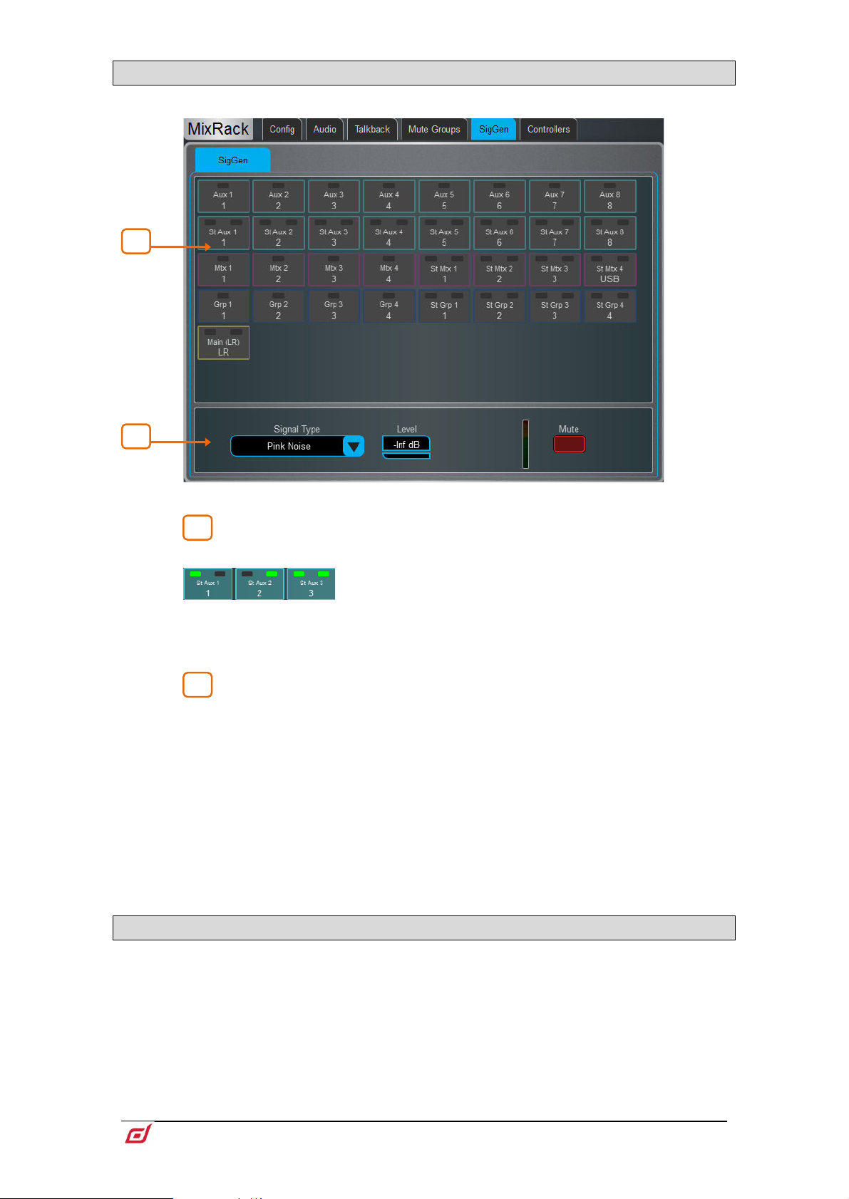
Firmware Reference Guide
73
V1.9
9.13 SigGen
1 2 2
1
The Signal Generator provides a test signal to help you align and test components of a sound system.
Assign – Touch a Mix button to assign the SigGen to that destination. Multiple
destinations can be assigned simultaneously.
Signal can be routed to one or both sides of a stereo Mix
by touching the left or right side of the stereo Mix button.
The signal routes through the Mix processing, therefore will be affected by the Mix EQ
and compressor.
The SigGen is disabled while Talkback is active.
Settings – The SigGen Level can be set from fully off to full scale +18dB.
Touch the Mute button to turn off.
There are 4 types of signal available:
Sine - A pure tone. Set the frequency using the Frequency box. This can be swept
across the full audio spectrum from 20Hz to 20kHz.
White Noise - A signal containing all audio frequencies with equal energy per Hz.
Pink Noise - A signal containing all audio frequencies with equal energy per octave,
a logarithmic curve and typically used for testing speakers and room response.
Band Pass Noise - Band filtered pink noise centred around the frequency set using
the Frequency control.
9.14 Controllers / Device Manager
Up to 8 GPIO modules and 16 IP remote controllers per device type are configurable, each with its own
assignments and functions.
Adding Remote Controllers to the
independent set of controls that can be used with or without Surface connection, for applications
such as personal monitoring, room control etc.
Refer to the Remote Controller Getting Started Guide for information on the device
hardware and connection.
MixRack / Controllers / Device Manager configures an
Page 74

Firmware Reference Guide
74
V1.9
Add a device to the Surface / Controllers / Device Manager instead to assign Sel and Mix keys
1
2
3
3
2
1
to the IP device and use the remote controller as an extension of the dLive Surface i.e. the
channel and Mix selection is shared across the Surface and IP device.
Select the device tab using the tabs on top, and select one of the 16 locations
in the list. The list shows the unit name of assigned devices.
The link icon will display green when the physical device is connected to the
network and synchronised. It will display red when the device is not present or
synchronising after being added.
The key and fader / rotary assignments for each device are stored in the dLive
Scenes. They are not stored on the physical device. These settings belong to the
device location in the list, for example you can assign functions and parameters to a
location prior to adding a device, or you can remove a device without affecting the
functions and parameters of its location.
Add Device – touch to assign a physical IP controller to the selected location
in the list.
Remove Device – touch to unassign an IP controller from the selected location.
Unit Name – touch to edit the name of the selected device.
Network – touch to edit the IP address, subnet, and DHCP setting for the selected
device. The default settings are:
IP6 IP 192.168.1.72 Subnet Mask 255.255.255.0 Gateway 192.168.1.254 DHCP off
IP8 IP 192.168.1.73 Subnet Mask 255.255.255.0 Gateway 192.168.1.254 DHCP off
To avoid network conflicts, make sure all connected IP controllers are assigned a
unique name and IP address.
Page 75

Firmware Reference Guide
75
V1.9
9.15 Controllers / Quick Setup
1 2 3
3
2
1
Quick Setup lets you quickly assign one or multiple channels to the IP controller strips, automatically
mapping the keys and faders / rotaries to a set of default functions and parameters.
⚙ Before you start, hold down Setup and touch anywhere in this screen to edit the
default settings for Quick Setup. These settings determine the function of the strips at
the moment of assigning to the IP device. They don’t affect strips which are already
assigned.
Drag and drop channels into the desired position in the lower window. Use the
tabs on the left to view different types of channels available, and the tabs on top to
navigate to higher / lower number channels.
Turn on Block Select and touch the first and last item you wish to assign to drag a
range of channels.
Drag channels out of the box to unassign.
Set the active Number of Layers from the dropdown menu and select the
Layer you want to assign channels to. Up to 6 SoftKeys on the IP Controller will be
automatically assigned to the Layer selection.
Page 76

Firmware Reference Guide
76
V1.9
9.16 Controllers / Advanced
1
2
3
3
2
1
Advanced allows one-by-one assignment of keys and faders / rotaries.
Touch a strip header to expand the view and display the assigned functions or
parameters for the strip.
Touch a control to assign a function or parameter. Note that the screen will
display two rows of rotary controls for the IP6. The lower row is the main function, the
upper row is the secondary (push ‘n turn) function. When assigning a level control to
a fader or rotary there is the choice of Audio Taper or user definable range.
When Audio Taper is enabled, the fader/encoder will use the same audio curve as
the Surface faders. If Audio Taper is disabled, a level range can be specified using
the Range Min and Range Max boxes. If the Min = -inf option is enabled then the
minimum level of the fader/encoder will be off (-inf) regardless of the range settings.
Select the Layer you want to edit.
Page 77

Firmware Reference Guide
77
V1.9
9.17 Controllers / Simulator
Use this screen to simulate the operation of the selected device.
Touch a key on the screen to control the assigned function. Touch a fader / rotary
control and use the Surface screen rotary encoder to control the assigned parameter.
Page 78

Firmware Reference Guide
78
V1.9
10. Surface Setup
1
2
2
1
These pages let you configure the Surface preferences, illumination, strip layout, audio and network
settings.
10.1 Control / Strip Assign
Any combination of Input channels, FX, Mix masters, DCAs and MIDI strips can be assigned to the 6 layers
of faders. This lets you customize the mixer layout to suit the application. The layout is stored within Scenes
and can be made Safe from Scene recall.
The factory Template Shows provide a classic layout with Input channels on the left and Mix masters on the
right to give you a starting point.
Current assignments are shown in the lower window arranged in Banks and Layers.
Drag and drop channels into the desired position in the lower window. Use the
tabs on the left to view different types of channels available, and the tabs on top to
navigate to higher / lower number channels.
Turn on Block Select and touch the first and last item you wish to assign to drag a
range of channels into the lower window. If you drop more channels than there are
strips available then they will wrap into the next Layer overwriting channels currently
assigned there.
Drag channels out of the window to unassign.
⚙ Hold down Setup and touch anywhere in the Strip Assign page to access the
assign preferences. Turn on Sync Selected Layer with Surface to make the screen
follow the active Layer on the Surface for the selected Bank.
Page 79

Firmware Reference Guide
79
V1.9
10.2 MIDI Strips
Fader strips can be assigned as MIDI Strips. There are 32 MIDI Strips available. Each can be assigned to
transmit a custom MIDI message. This is ideal for controlling audio within a Digital Audio Workstation
(DAW), a slave mixer, or parameters on external equipment such as effects devices. MIDI Strips can be
named and coloured. They are stored within Scenes and can be made Safe from Scene recall.
Custom MIDI messages can be assigned to faders, all six rotary functions (Gain, Pan and Custom 1-4),
Mute, Mix and PAFL keys. To configure the messages press the MIDI Strip
Sel key.
MIDI Strip – Touch the top left box to set name and colour for the MIDI Strip. Touch
a control box to type in a custom MIDI message where <VAR> represents a variable
value.
Turn Local on if you want the key LED indicator to follow local presses. Turn this off if
you want the indicator to follow remote messages (MIDI tally).
The following default CC and Note on/off messages are assigned within the factory
Template Shows for MIDI Strips 1-32 (hex values shown):
• Fader =
• Rotary Gain = B2, 00, <VAR> to B2, 1F, <VAR>
• Rotary Pan = B2, 20, <VAR> to B2, 3F, <VAR>
• Rotary Custom 1 =
• Rotary Custom 2 =
• Mute key = 91, 00, <VAR> to 91, 1F, <VAR>
• Mix key = 91, 20, <VAR> to 91, 3F, <VAR>
• PAFL key = 91, 40, <VAR> to 91, 5F, <VAR>
You can restore the factory default MIDI messages by recalling the ‘Reset MIDI’
Scene in the Template Shows. This resets the messages for all 32 MIDI strips.
Download the MIDI Control Driver from www.allen-heath.com to convert the default
MIDI messages to popular HUI or Mackie Control protocols for DAW use. Levels and
On/Off commands can also be sent and received in CC format using MIDI Control
Driver as a translator. A MIDI Thru option is available for a straight throughput of the
MIDI messages with no translation of A&H MIDI messages. The MIDI Control driver is
available for Windows and MacOS.
B1, 00, <VAR> to B1, 1F, <VAR>
B2, 40, <VAR> to B2, 5F, <VAR>
B2, 60, <VAR> to B2, 7F, <VAR>
Page 80
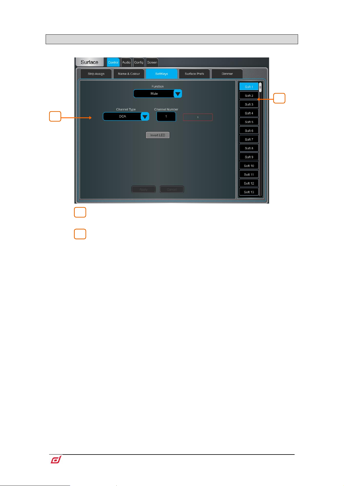
Firmware Reference Guide
80
V1.9
1
2
2
1
10.3 Control / SoftKeys
dLive Surfaces provide up to 26 assignable keys on the right of the Surface, depending on model.
Touch one of the SoftKeys buttons on the right of the screen to select it. Swipe
up / down to scroll.
Open the Function drop-down menu and select the function to assign. Set the
Channel Type and Channel Number to select the required channel (only applies to
certain functions). Turn on Invert LED if you want the SoftKey LED to be lit when the
function is off. Press Apply to confirm the changes.
SoftKey assignments are store within Scenes. To prevent SoftKey assignments to
be overwritten on Scene recall, you can make one, a selection or all Safe using the
Scenes / Global Scene Safes screen.
Available SoftKey functions are as follows:
• Unused
• ABCD Set All – Sets all Input Channels to the selected ABCD Source.
• ABCD Set Channel – Sets specific Input Channel to the selected ABCD Source.
• ABCD Set Range – Sets range of Input Channels to the selected ABCD Source.
• ABCD Set For DCA – Sets all DCA member channels to the selected ABCD
Source.
• AMM Control – Turns on/off an AMM zone or an individual channel in an AMM.
• Assign ON/OFF – Toggles the send assign for an Input/FX Return to a Mix, Mute
Group, DCA or engineer’s IEM/Wedge bus.
• Bookmark – Navigate directly to a selected screen or tab.
• Channel Processing – Insert or Bypass a specific channel processing block.
• Custom MIDI - Transmit a custom MIDI message string.
• DCA/MCA Spill Active – Turns DCA/MCA Spill mode on/off.
• Fader On-Off – Illuminates when the selected channel fader is at a value higher
than -inf.
• Fader Start – Momentarily illuminates when the selected channel fader moves
from –inf.
• Level Down – Tap to decrease a fader level.
• Level Up – Tap to increase a fader level.
• MCA On/Off Selected DCAs – Toggles MCA mode for DCAs selected in Bank
view.
• MCA On/Off Specific DCA – Toggles MCA mode on a specific DCA.
• MCA On/Off All DCAs – Toggles MCA mode on all DCAs.
• Mix – Quick access to a specific Mix.
Page 81
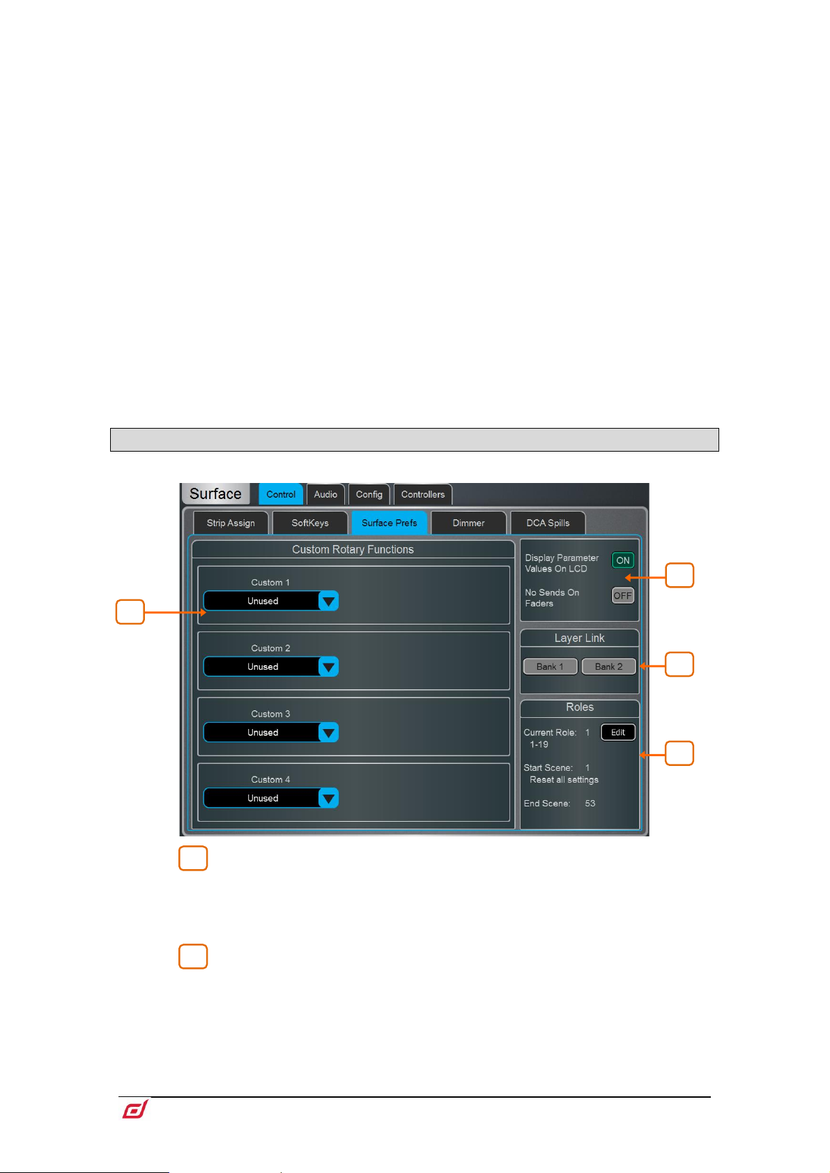
Firmware Reference Guide
81
V1.9
• Mute – Mute control for any input channel, bus or DCA.
1
2
4 3 1
2
• Mute Group – Mutes/unmutes the specified Mute Group.
• PAFL – Enables PAFL on a selected channel and PAFL bus.
• PAFL Clear – Turns off all currently active PAFL selections.
• PAFL Surface Number – Sets the Surface PAFL to the PAFL bus selected.
• Peak Hold Reset – Clear all current Peak Hold indicators.
• Scene Controls – Quick access to scene controls (Recall, Store etc.).
• Sel – Selects a specific channel.
• Sel Mix PAFL Scene – Combination on single key, for example to recall a
specific per-Mix strip layout when mixing monitors.
• Send Level Down – Tap to decrease level for Aux/FX/Matrix sends with the
option to set a Max/Min gain range.
• Send Level Up – Tap to increase level for AuxFX/Matrix sends with the option to
set a Max/Min gain range.
• SIP – Press and hold for 1 second to activate Solo In Place (SIP).
• Talkback Additive Groups – Toggle Talkback Additive mode.
• Talkback Assign – Talkback to different outputs.
• Talkback Group – Turn on Talkback to a specified Talkback Group with
selectable latching or momentary switch behaviour.
• Tap Tempo - Assign to any of the 16 FX L or R tap or as a Global Tempo.
• USB Play/Record – Control USB transport from the current Surface.
• Virtual Sound Check – Set Virtual Sound Check mode.
10.4 Control / Surface Preferences
Custom Rotary Functions – Use the drop-down menus to select the
required Function for each Custom strip rotary control. Available functions are Direct
Out, Send Level (Aux or FX sends), HPF/LPF Frequency, Compressor/Gate
Threshold, Gate Depth, Channel Level, AMM Priority Level, LCR+ Divergence,
Front/Rear Pan, Stereo Width. Touch Apply to confirm the change.
Display Parameter Values on LCD will display the fader position in dB value
or value of the rotary function every time the fader or rotary are moved.
No Sends On Faders inhibits sends on faders when pressing any
channel faders will always control the Input main levels or Mix masters when this
option is enabled. You can still control the send levels by using the strip rotary Sends
function, Soft Rotaries Sends widget, or touchscreen
Routing screen.
Mix key. The
Page 82
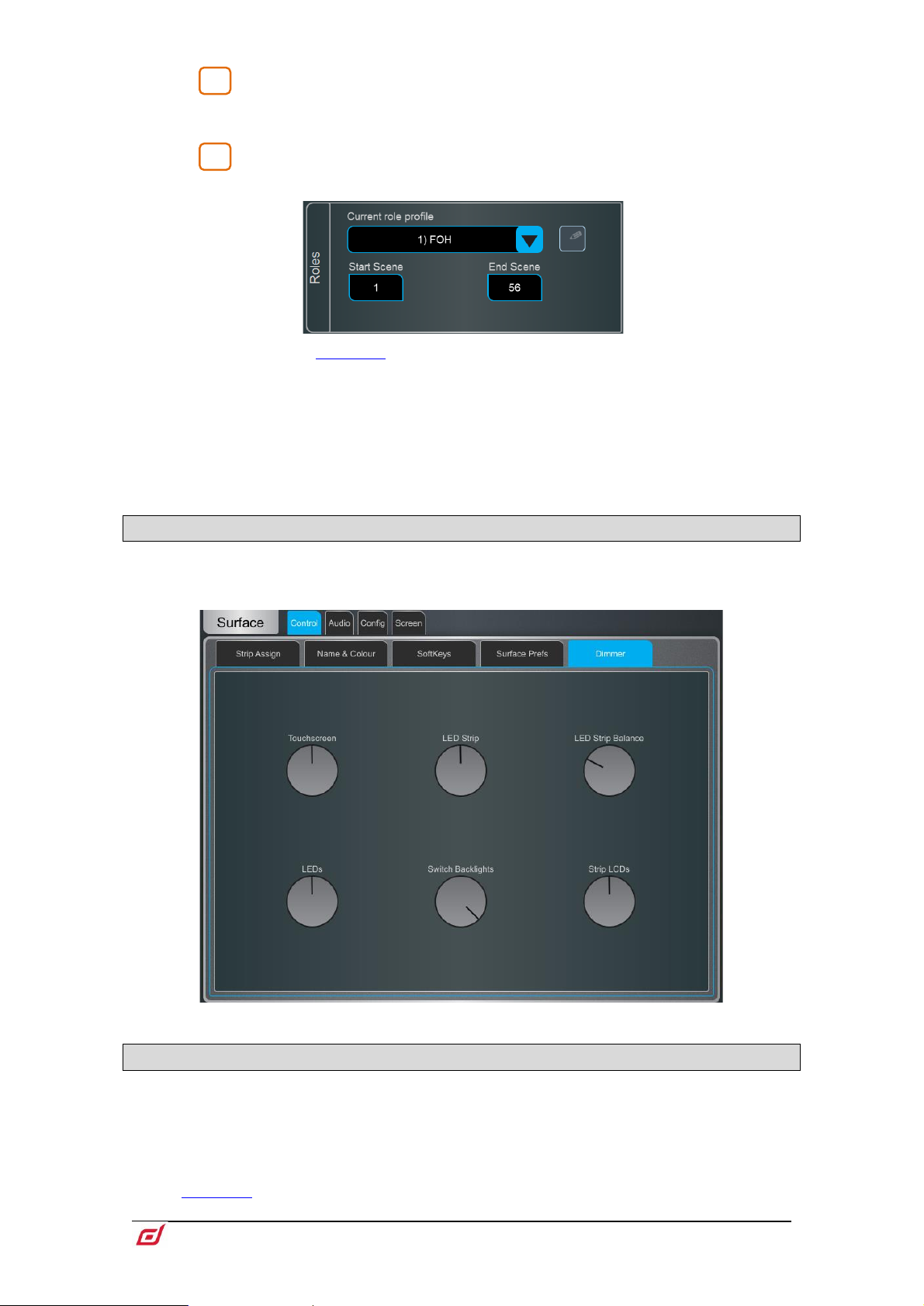
Firmware Reference Guide
82
V1.9
Layer Link – Touch the buttons to link or unlink the Layers across the fader
3
3
banks. Selecting a Layer on a linked bank will select the same Layer across all linked
banks.
Roles - Allows you to configure up to 4 Surface roles, each with a separate
scene range and role filter.
See section on Role Filters in this guide for more details on Role Filters.
Clicking on the edit icon lets you name each role, for example FOH, MON, REC,
BROADCAST.
Each role can be assigned a range of Scenes using the Start Scene and End Scene
boxes. Scenes outside of the specified range will not be accessible from this Surface
role. This is useful for multi-surface setups where the engineers require independent
scene ranges.
10.5 Control / Dimmer
Use this page to separately adjust the brightness of the touchscreen, LEDs, switch backlights, fader strip
LCD displays, and intensity and colour tone of the integrated LED strip illumination. These settings are
stored in Scene memories.
10.6 Control / DCA/MCA Options
DCA/MCA Spills populate the Surface with only the channels assigned to a DCA/MCA, temporarily
overriding the current strip layout, whenever a DCA/MCA Mix button is pressed.
The DCA/MCA Mix function can be assigned to SoftKeys, which allows spills to be used when DCA/MCA
strips are not in the active Layer, or even dedicate some DCAs as pure ‘population groups’ without a fader.
Go to
See Appendix F in this guide for more details on MCA functionality.
Surface / Control / SoftKeys to assign.
Page 83
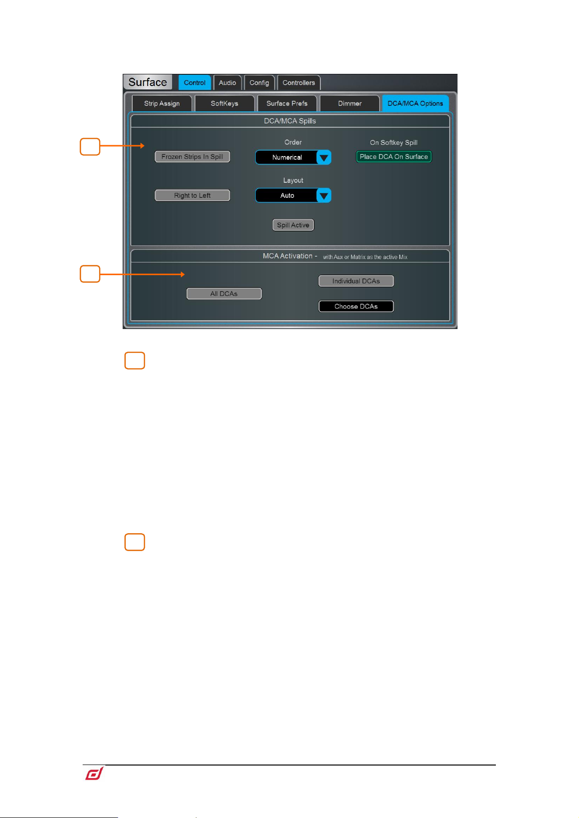
Firmware Reference Guide
83
V1.9
1 4 2
1
.
DCA/MCA Spills
Select the Order in which the channels are displayed on the Surface. Set to
Numerical to follow the channel number, or Strip to follow the order of the strip layout
at the moment of the spill.
Enable Frozen Strips in Spill to keep frozen fader strips in view during a spill.
Enable Place DCA On Surface to keep the DCA master in view during a spill. This is
useful if all fader banks are used for the spill, for example on a C1500 Surface.
Set the Layout to Auto to automatically spill to the fader banks not used by the
DCA/MCA, or Manual to manually select the fader banks for the spill. Enable Right to
Left to populate banks in reverse, starting from the right-hand side.
Touch Spill Active to enable or disable the DCA/MCA Spills function globally. This
switch can be assigned to a SoftKey and used as a quick way to restore the normal
strip layout whichever spill might be active.
MCA Activation
Enable All DCAs to have all DCAs operate in MCA mode when an Aux or Matrix is the
active Mix, or enable Individual DCAs and press Choose DCAs to select. Individual
DCAs can be also set to MCA mode in
Processing / Bank View.
Page 84
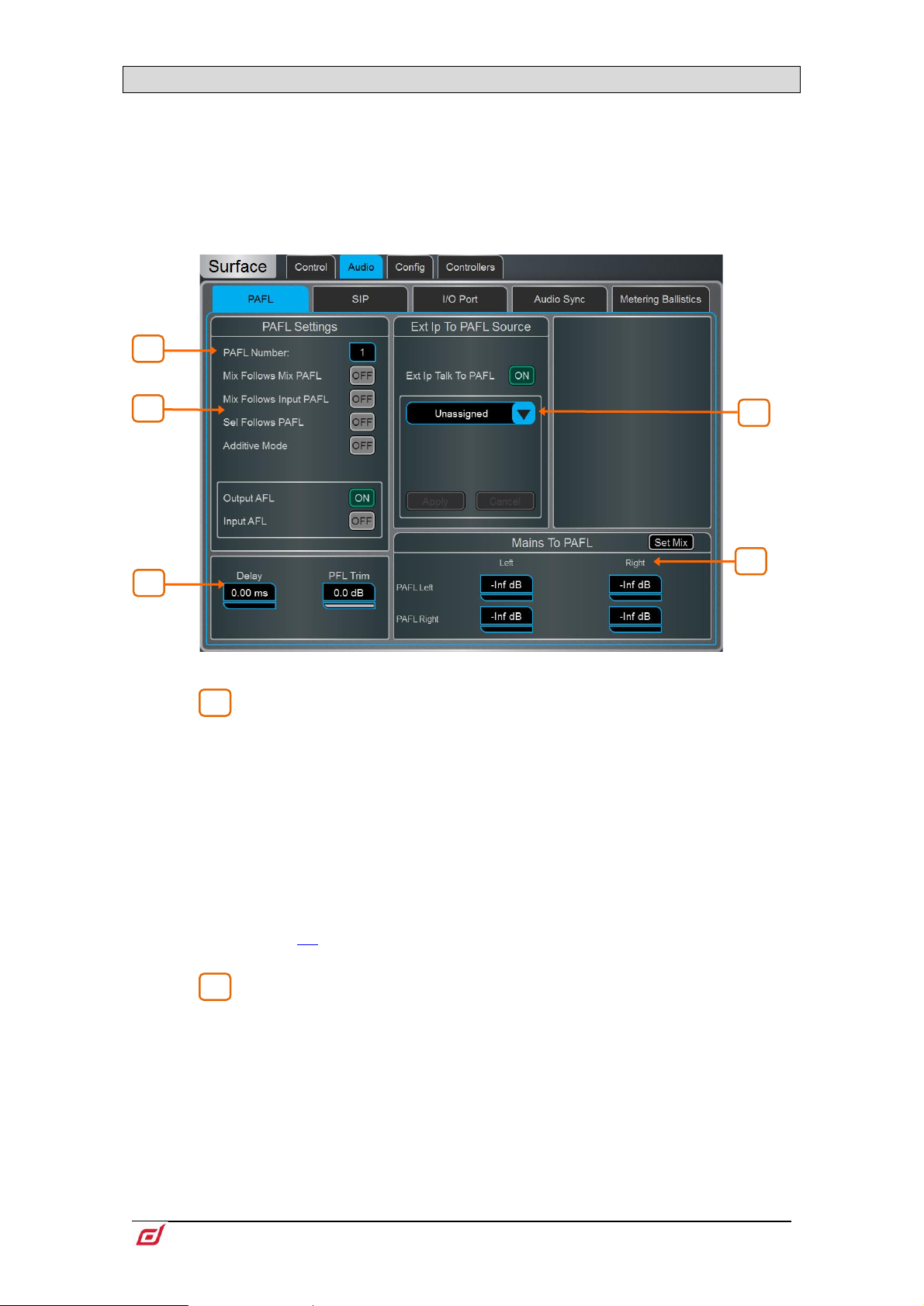
Firmware Reference Guide
84
V1.9
10.7 Audio / PAFL
1
2
2 4 5
3
1
Set your preferences for the PAFL monitoring system.
The strip PAFL key operates in the following way:
• Mix PAFL overrides Mains in the monitor
• Input PAFL overrides Mix PAFL
• Releasing Input PAFL restores previous Mix PAFL
• Pressing Mix PAFL clears any Input PAFL
PAFL Number – Set the PAFL bus that the Surface will use for the
monitoring system. This affects the function of the PAFL keys, Listen key, and audio
to the Surface headphones.
When more than 1 PAFL bus is configured in the
screen, multiple operators can share the same dLive system whilst using different
PAFL busses.
The MixRack headphones output is fixed to PAFL bus 1
The RTA function is fixed to PAFL bus 1
Wedge and IEM strips are fixed to PAFL bus 1
PFL Trim is not present on PAFL bus 9 and 10.
When using SIP (Solo In Place), the PAFL Number should match PAFL Used For
SIP number
Mix Follows Mix PAFL automatically makes a
key is pressed.
Mix Follows Input PAFL automatically makes a
key is pressed.
Sel Follows PAFL automatically selects a channel when its PAFL key is pressed.
Additive Mode sums PAFL selections when turned on. Selections auto-cancel when
turned off.
Select either PFL (pre-fade listen) or AFL (after-fade listen) for Input channels and Mix
(Output) masters when the strip PAFL keys are pressed.
Mixer / Config / Mixer Config
Mix key active when a Mix PAFL
Mix key active when an Input PAFL
Page 85
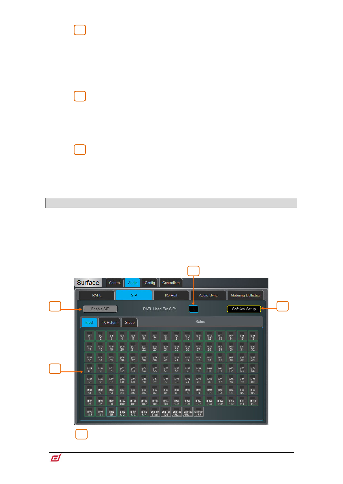
Firmware Reference Guide
85
V1.9
Ext Input to PAFL Source – Use the drop-down menu to select and
3
4
5
1
1
4
3
2
assign an external signal, Group, Aux, Matrix or Main to the PAFL monitor, for example
an I/O Port input for ‘shout’ communication between FoH and Monitor engineers. The
signal will not be affected by the engineer’s Wedge or IEM fader strip level.
Either the Left or Right channel must be selected when assigning stereo Groups,
Aux, Matrix or Main busses to Ext Ip Talk To PAFL.
When assigned, controls for the preamp Gain, Trim, PAD and phantom power will
appear in the window to the right.
A Delay up to 680ms can be set to align the PAFL signal with the acoustic
sound from the stage.
PFL Trim attenuates the PFL signal by up to 24dB relative to the AFL signal. This
avoids loud PFL levels in situations where the Mix output levels are low.
PAFL Delay settings are reset to 0ms if a bus configuration change is made in
Mixer / Config / Mixer Config
Mix to PAFL – Set how much of the selected mix goes to the monitor system
when no PAFL is active. Touch the Set Mix button to select a mix (Mains, Group, Aux
or Matrix)
It is typical, for example, to have Main Left and Right feed the PAFL Left and Right
busses in a FOH application, or a specific performers IEM mix in a MON application.
10.8 Audio / SIP
Configure and enable/disable SIP (Solo In Place).
When SIP is enabled, channel PAFL buttons on connected Surface(s), Director and IP
Controllers will function as a SIP button.
SIP can be used to listen to one or more channels (Inputs, Groups and FX Returns) in isolation
through the main outputs of a system. When SIP is active on one or more channels, all other
channels are muted unless they have been made Solo Safe.
SIP affects the audio to all outputs in the system and should be used with care.
PAFL Used For SIP – Select the correct PAFL number to use for SIP control.
Page 86
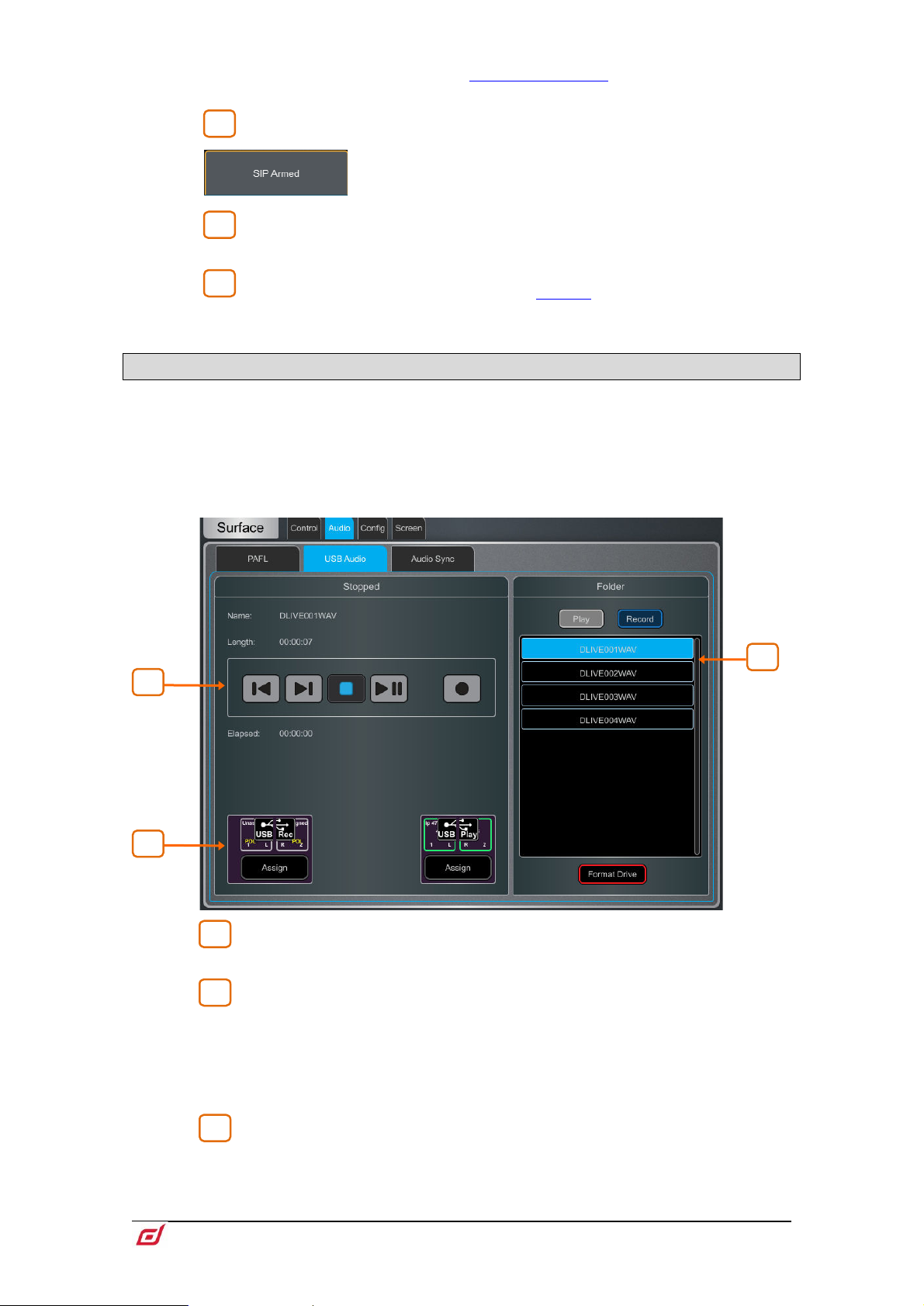
Firmware Reference Guide
86
V1.9
This should be the same number as the Surface PAFL Number. If the numbers do
2 3 4
1
2
3
1 3 2
not match, the channel PAFL buttons will not activate SIP.
Enable/Disable SIP – Touch to enable or disable SIP.
When enabled, a “SIP Armed” notification will appear near
the bottom of the screen. Touch this notification to return
to the SIP screen at any point.
Solo Safe – Select Input, Group and FX Return channels to be made Solo
Safe. Channels which are made Solo Safe will not be muted when SIP is active.
SoftKey Setup – Touch to access the
Enable/Disable can be assigned to a Surface, Director or IP Controller SoftKey.
SoftKeys screen where SIP
10.9 Audio / USB Audio
Set up and manage stereo recording and playback to a USB key. dLive can play mono or stereo WAV files,
16bit or 24bit, with sample rate of 44.1, 48 or 96kHz. USB recording is fixed stereo WAV 24bit 96kHz
(approximately 34MB per minute or 2GB per hour).
The USB key must be formatted FAT32 with 32k cluster size. We recommend you
format the key using this page prior to use.
Use the transport buttons to Play, Pause, Stop, Record and select previous or
next track. To record, press Record to arm the recording, then press Play.
Folder – Choose to display audio files present in the USB key Play or Record
folder. The two folders are named
respectively and are automatically created when a USB key is plugged into the
Record/Playback USB port.
Scroll through the list and touch a track to select. The name and length will be
displayed in the left window.
AHDLIVE/USBPLAY and AHDLIVE/USBREC
The current source for USB recording and USB Playback patch is displayed.
Touch the Assign button to open the
I/O screen and assign source or destination.
Page 87
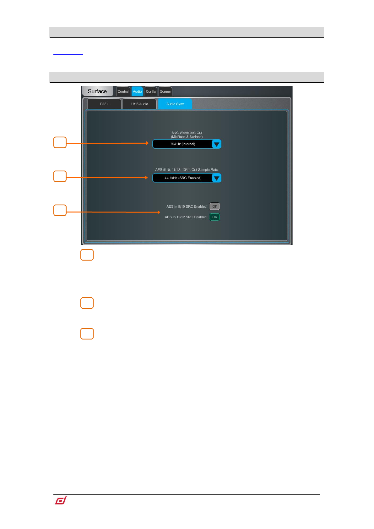
Firmware Reference Guide
87
V1.9
10.10 Audio / I/O Port
1
2
3
3
1
2
These tabs display information on the fitted I/O Port card/s, and give access to any relevant option. See
Appendix D in this guide for details.
10.11 Audio / Audio Sync
BNC Wordclock Out – Select the sample rate for the Wordclock output
provided at the Surface and MixRack. This can be set to Off, 44.1kHz, 48kHz or
96kHz (internal).
When using a dLive C Class Surface, an option is displayed in this page to set the
BNC connector as either a Wordclock input or output.
AES Out Sample Rate – Select the sample rate for the Surface AES3
outputs. This can be set to 44.1kHz, 48kHz or 96kHz. Sample Rate Conversion will
be bypassed when set to 96kHz.
You can turn the Sample Rate Conversion on or off for each stereo AES3 input
as required.
Only turn off SRC if the AES sources are syncing from a 96kHz clock provided by
the dLive.
Page 88
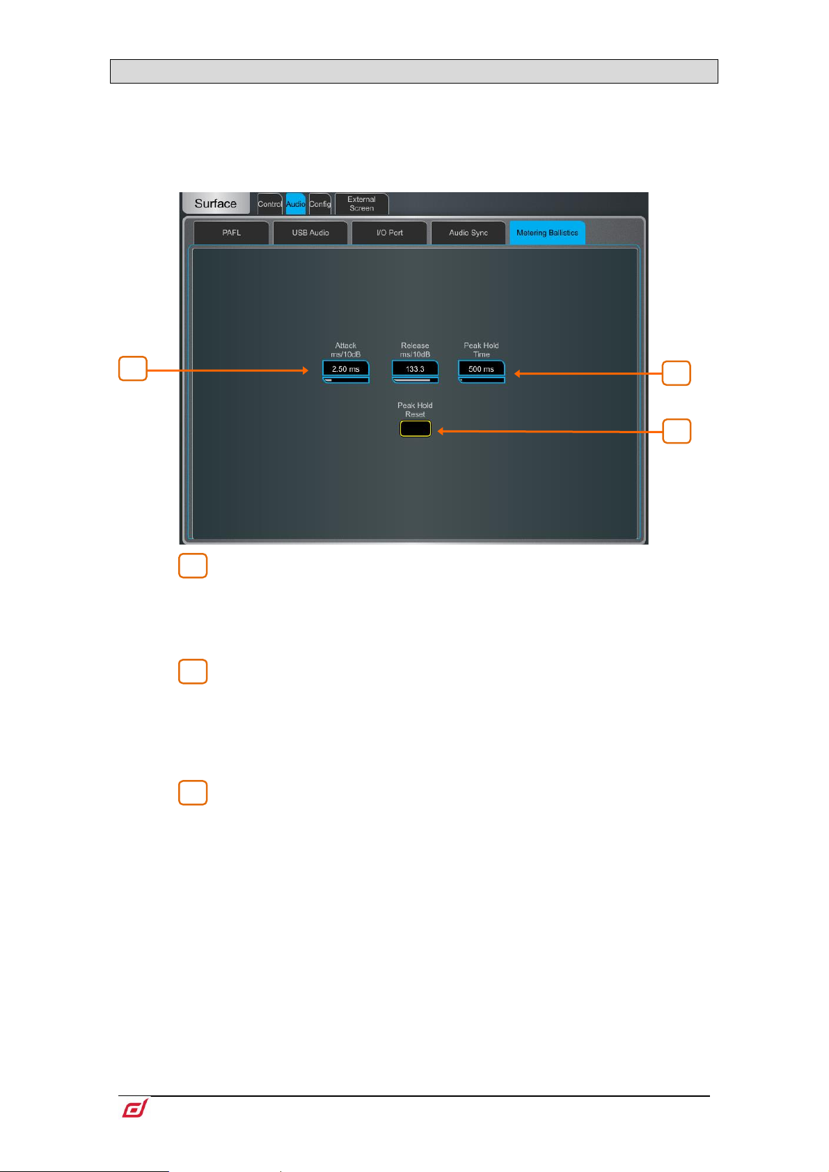
Firmware Reference Guide
88
V1.9
10.12 Audio / Metering Ballistics
1
2
3
3 2 1
The response of dLive meters on screen and Surface can be tweaked to suit the engineer’s preference.
To set the global meter source point for Input channels and Mix masters, hold
down Setup and touch the main screen area in the Meters / Inputs or Meters /
Mix screen.
Use fast Attack and Release for fast response, digital absolute peak meters.
This ensures you keep control and avoid digital clipping of signals including those
with very fast dynamics, but note that the meters may read hotter than those on other
consoles you are used to.
Use slower Attack and Release to ‘dampen’ the response if required.
The Peak Hold Time can be set from 40ms to 10s or to infinite. This is the
amount of time the highest segment of the meter will stay lit and indicates the highest
signal level within such time. It also affects the red Peak indicator.
The red peak indicator lights to warn that the signal is within 5dB of clipping. It is
multi-point sensing which means it detects peak activity at several points in the
signal path.
Touch Peak Hold Reset to clear all current Peak Hold indicators.
Page 89
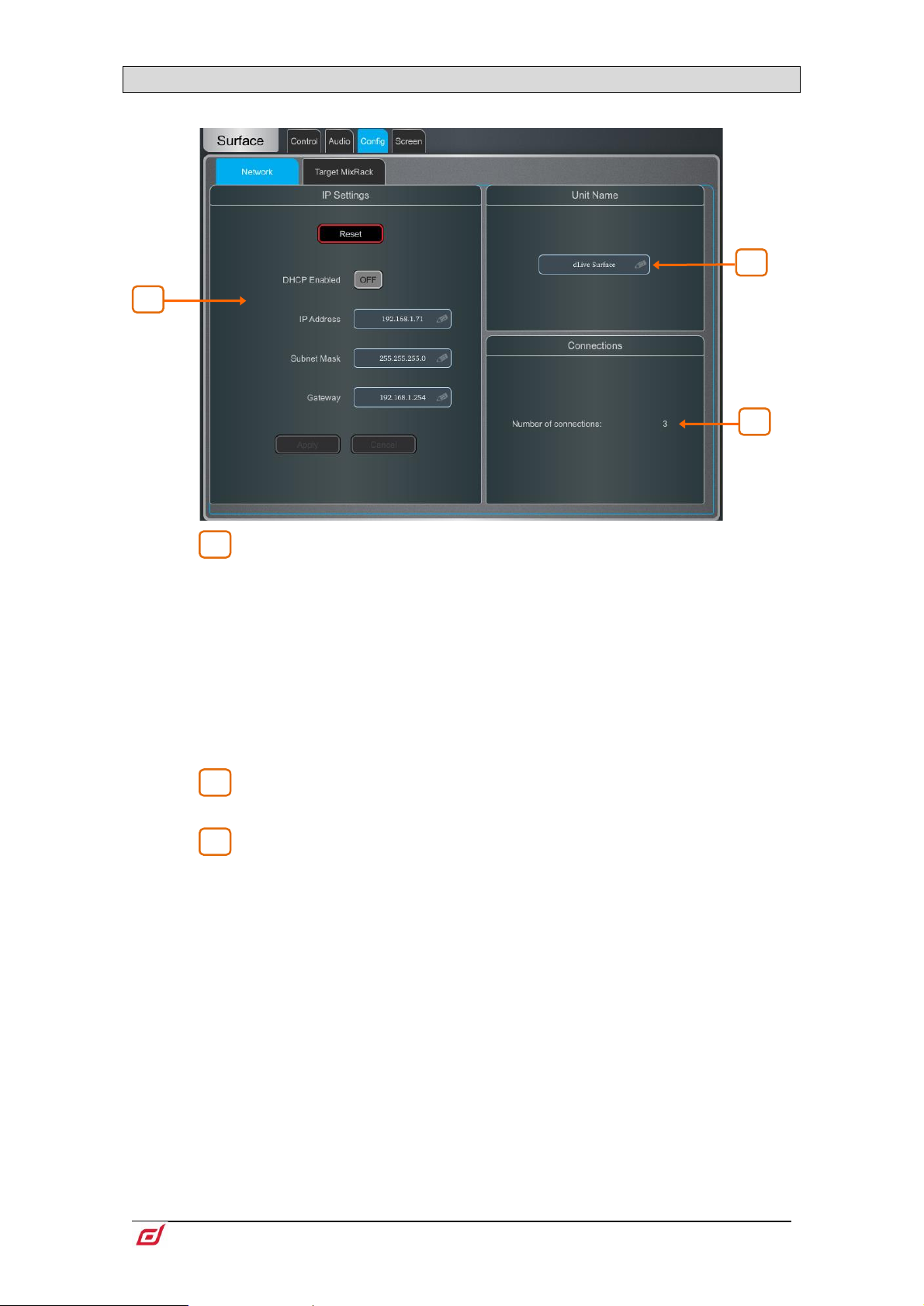
Firmware Reference Guide
89
V1.9
10.13 Config / Network
1
2
3
2 3 1
Use this page to configure the IP Address and Unit Name to identify the Surface on the network.
IP Settings – To set a static IP Address, touch the IP Address box and type
in the address. Make sure the Subnet Mask and Gateway are valid, and all devices on
the network including Wi-Fi routers, access points or laptops have unique but
compatible addresses.
The default Surface IP Address is 192.168.1.71 with Subnet Mask 255.255.255.0 and
Gateway 192.168.1.254. You can restore these defaults by touching the Reset button.
Enable DHCP to allocate an IP Address to the Surface by a network DHCP server, for
example a Wi-Fi router.
Only use DHCP when a DHCP server is connected to the Surface. If DHCP is
enabled and the Surface is powered up while no server is present, it can take longer
than usual for the system to boot.
Unit Name – A name with up to 16 characters can be set to identify the
Surface on the network. The default is ‘dLive Surface’.
Connections – Displays the number of active network connections to the
MixRack. The Surface and touchscreens count as one connection each.
Page 90

Firmware Reference Guide
90
V1.9
10.14 Config / Target MixRack
1
1
On this page a MixRack can be selected for connection to the Surface.
Target MixRack – The Surface remembers the last MixRack it connected
to and attempts to connect to it at power up. If you want to connect the Surface to a
different MixRack on the network, select the MixRack from the list or type in its IP
Address and press Apply.
10.15 External Screen
Use this page to select the output of the external VGA connector. The VGA output can mirror either screen
of the dLive Surface, or set to display a third, independent view.
You can connect a mouse and/or keyboard to the Surface USB port/s for use with the external screen.
The external screen must support a resolution of 1024x768.
External touchscreen devices can be used if they support a resolution of 1024x768
and are class compliant on Linux. dLive does not support third party driver installation.
10.16 Controllers
Up to 8 GPIO modules and 16 IP remote controllers per device type are configurable, each with its own
assignments and functions.
Refer to the Remote Controller Getting Started Guide for information on the device
hardware and connection.
Please refer to earlier sections in this Guide for instructions on setting up and
assigning IP remote controllers.
Adding a device to the Surface / Controllers / Device Manager adds the option to assign Sel
and Mix keys to the IP device. In this mode the remote controller becomes an extension of the
dLive Surface i.e. the channel and Mix selection is shared across the Surface and IP device.
Add controllers to the MixRack / Controllers / Device Manager instead for applications where
the Surface is not present or an independent set of controls is required.
Page 91
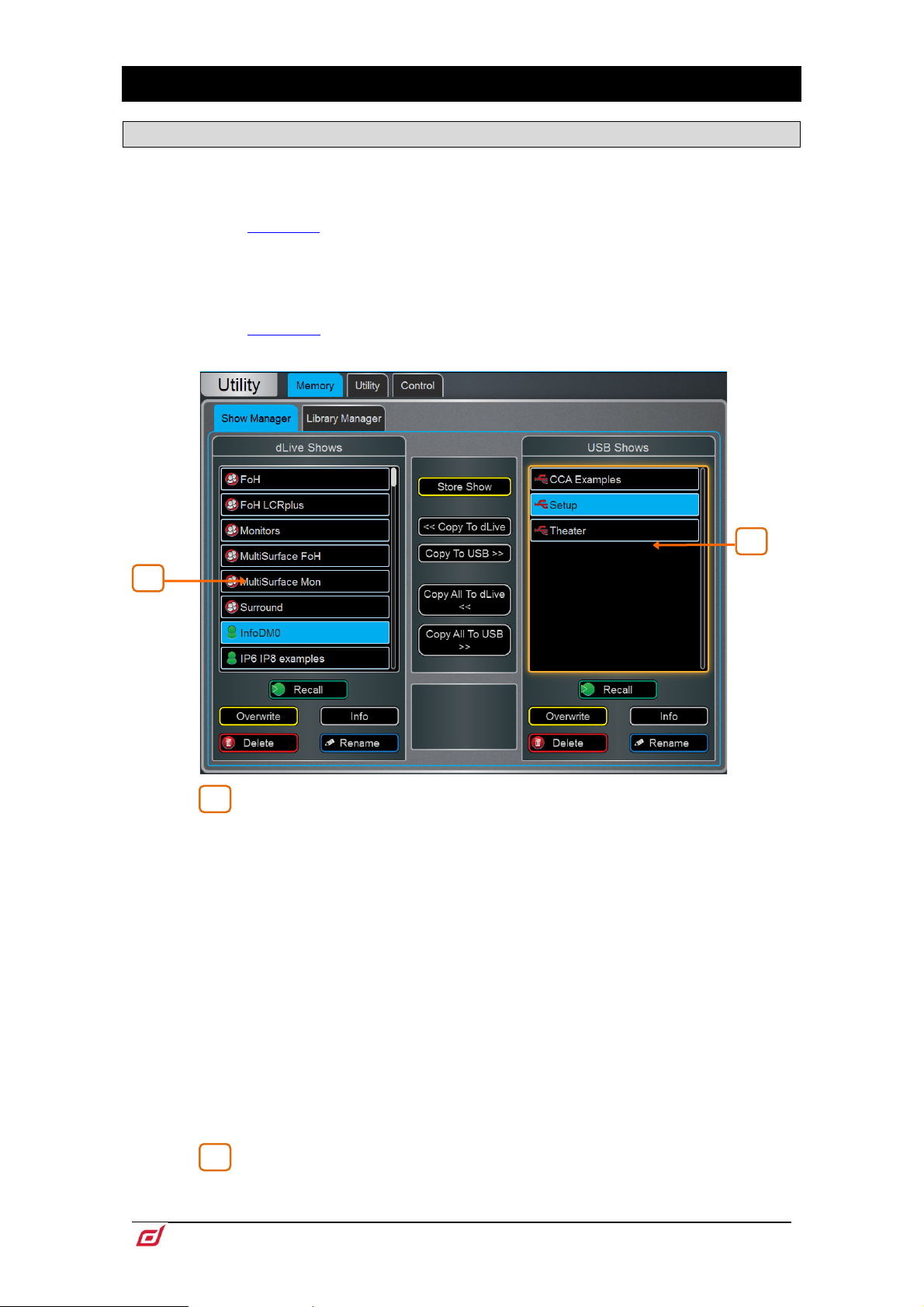
Firmware Reference Guide
91
V1.9
11. Shows / Utility
1
2
1
2
11.1 Memory / Show Manager
A Show file stores the complete dLive setup. This includes the mixer bus configuration, system preferences,
all Scene memories and all Libraries. User Profiles are not stored in Show files. Shows are stored in the
dLive Surface and can be transferred between dLive systems or archived via USB key.
See Appendix B in this guide for details on Scene and Show memory content.
User Shows can be overwritten, renamed or deleted. Factory Template Shows provide a quick starting
point by giving you a familiar layout and classic mix architecture for typical FoH and Monitor applications.
Template Shows cannot be edited or deleted. They contain a number of default Scenes to reset the mixer
settings, patch and Surface layout to the starting point.
See Appendix C in this guide for an overview of available Template Shows.
dLive Shows – Lists Template and User Shows stored in the dLive Surface
or Director. Touch Store Show and type in a name to store a new User Show.
Touch a Show to select it and press Overwrite to update it with current settings. You
can Rename and Delete existing Shows. Touch Info to display the file size of the
Show and the date it was last modified. Touch Recall and confirm to recall a Show.
When loading a show created in earlier firmware, a message will appear warning you
that new features will not be reset. If you select Yes to load the show you should then
check the parameters of any new features before proceeding, to ensure they are set
appropriately.
Recalling a Show overwrites all system settings, bus configuration, Scenes and
Libraries. If you want to keep your current settings for later use, archive them first as
a User Show.
Recalling a Show will briefly interrupt the audio. It is not intended for instant recall
of band settings or theatre cues. Use Scenes for such applications instead.
dLive Shows stored on systems running more recent firmware will not load on
systems running earlier versions. However, earlier versions of Shows are compatible
with dLive systems running later firmware.
USB Shows – Lists User Shows stored in the USB drive. The files are stored
in the USB AllenHeath-dLive/Shows folder. Touch a Show to select it and press
Overwrite to update it with current settings. You can Rename and Delete existing
Page 92

Firmware Reference Guide
92
V1.9
Shows. Touch Info to display the file size of the Show and the date it was last modified.
1
2
2
1
Touch Recall and confirm to recall a Show.
Select a USB Show and touch Copy to dLive to copy the file to the dLive memory.
Select a dLive Show and touch Copy to USB to copy the file to the USB drive. Touch
Copy All to… to transfer all Show files.
⚙ Hold down Setup and touch anywhere in this screen to access Show Manager
Options. Enable Allow Surface Only Recall to only recall the surface data from a
show. MixRack data will not be affected by a show recall when this option is enabled.
This option would typically be used when in Multi-Surface mode so
settings and audio on the MixRack and Primary Surface wouldn’t be disrupted when
a Show is recalled on the Secondary Surface. See Appendix E for more information.
that current
11.2 Memory / Library Manager
Use this page to edit and transfer Library presets. Library memories include Channel Processing, Mix
Processing, PEQ, GEQ, Gate, Compressor, FX parameters.
dLive Libraries – Lists Libraries stored in the current Show. Touch a Library
to select it. You can Rename and Delete existing Libraries. Touch Copy to USB to
copy the Library to the USB drive.
USB Libraries – Lists Libraries stored in the USB drive. The files are stored
in the USB
to dLive to copy the Library to the dLive memory.
dLive Libraries are stored within a Show file. If you want to use one or more Library
in a different Show, archive them first to USB, recall the Show, and transfer the
Libraries back to the dLive.
AllenHeath-dLive/Libraries folder. Touch a Library to select it. Touch Copy
Page 93

Firmware Reference Guide
93
V1.9
11.3 Utility / History
1
1
This page keeps a timed register of events such as system boot up or shut down, when Scenes are recalled,
and any error recognized by the system.
If you suspect a problem with the dLive system you can Copy the logs to USB
Key and send them to Allen & Heath Product Support for diagnostic purposes.
Any time an error is logged a warning message will appear in the Home screen
and a yellow triangle is displayed in the top right corner of the screen. Touch the
triangle to navigate to the Home screen and investigate the error.
⚙ Hold down Setup and touch anywhere in this screen to access an option to Show
detailed Event Logs.
Page 94

Firmware Reference Guide
94
V1.9
11.4 Utility / Date/Time
Use this page to set the current date and time. The time is displayed in the Home screen and used in the
History and Event Logs.
11.5 Utility / Calibration
This page lets you recalibrate the accuracy of the motor faders and touchscreens.
To calibrate the faders, touch the Calibrate button and follow the on-screen instructions, moving
the faders to the positions instructed at each step.
It may be necessary to re-calibrate the motor faders after you update the firmware
or perform a full system reset.
To calibrate the touchscreen, touch the Calibrate button and wait for the automated procedure
to complete.
11.6 Utility / Diagnostic
This page lets you diagnose any hardware faults with your dLive Surface screens, meters, LEDs and
controls.
In Automatic mode, the Surface will sequence through different fader positions and different
colours and levels of brightness for LEDs, touchscreens and LCD displays.
In Manual mode, you can check for correct operation of keys and rotaries. Press any illuminated
key to turn off their illumination. Press any non-illuminated key to remove it from the list on screen.
Turn rotaries one full revolution to turn their illumination.
11.7 Utility / Firmware
Use this page to view or update the current firmware. Firmware is updated via a USB drive or Director.
Keep your dLive system updated with the latest version of firmware. Check
www.allen-heath.com for the latest version and information.
Updating dLive firmware resets its parameters and preferences. If you want to keep
your current settings save these as a User Show first. Updating firmware does not
affect User Shows or User Profiles.
Page 95

Firmware Reference Guide
95
V1.9
dLive Shows stored on systems running more recent firmware will not load on
systems running earlier versions. However, earlier versions of Shows are compatible
with dLive systems running later firmware.
In a Multi-Surface configuration, Surfaces should be updated individually – either
connected as a Primary Surface or with no MixRack present and via the Connection
Failed screen. Updating the firmware with Secondary Surfaces connected via
gigaACE I/O modules is not supported.
When downgrading from v1.90 or higher to any pre-1.90 version of the firmware, it
may be required to set Jumper 3 into the On position in the MixRack. For jumper
location please see “dLive. MixRack hard reset” in the Allen & Heath knowledgebase.
To update the firmware via USB:
1. Download the latest firmware from www.allen-heath.com and save the .zip file.
2. Remove any previous dLive firmware from your USB drive. To do this, look into the USB
AllenHeath-dLive folder and delete the existing Firmware folder and also the Firmware.md5 file.
Do not delete other files or folders.
3. Open and extract the .zip file to the root directory of your USB drive.
Do not change the folder name or browse inside the Firmware folder as doing this
may cause firmware corruption. Attempting to navigate or open files within this
directory may cause your Operating System to leave behind small temporary system
files which can invalidate your firmware.
4. Safely remove the USB drive from your computer.
5. Plug the USB drive into the dLive USB port, and touch Update in the Firmware page.
The dLive will reboot to a ‘bootloader’ screen and if valid firmware is found on the
USB drive then details of the current versions and versions found on the drive will be
displayed.
6. Touch the Update button.
Do not interrupt this process. Failure to complete the transfer may result in
firmware corruption. Make sure the mains power and connecting cables are reliable
and that the system will not be disturbed or switched off during the update.
7. When the firmware has been successfully installed, the system will automatically
reboot.
8. Once the system is fully booted, recall a Template Show or User Show to restore your
settings.
Page 96
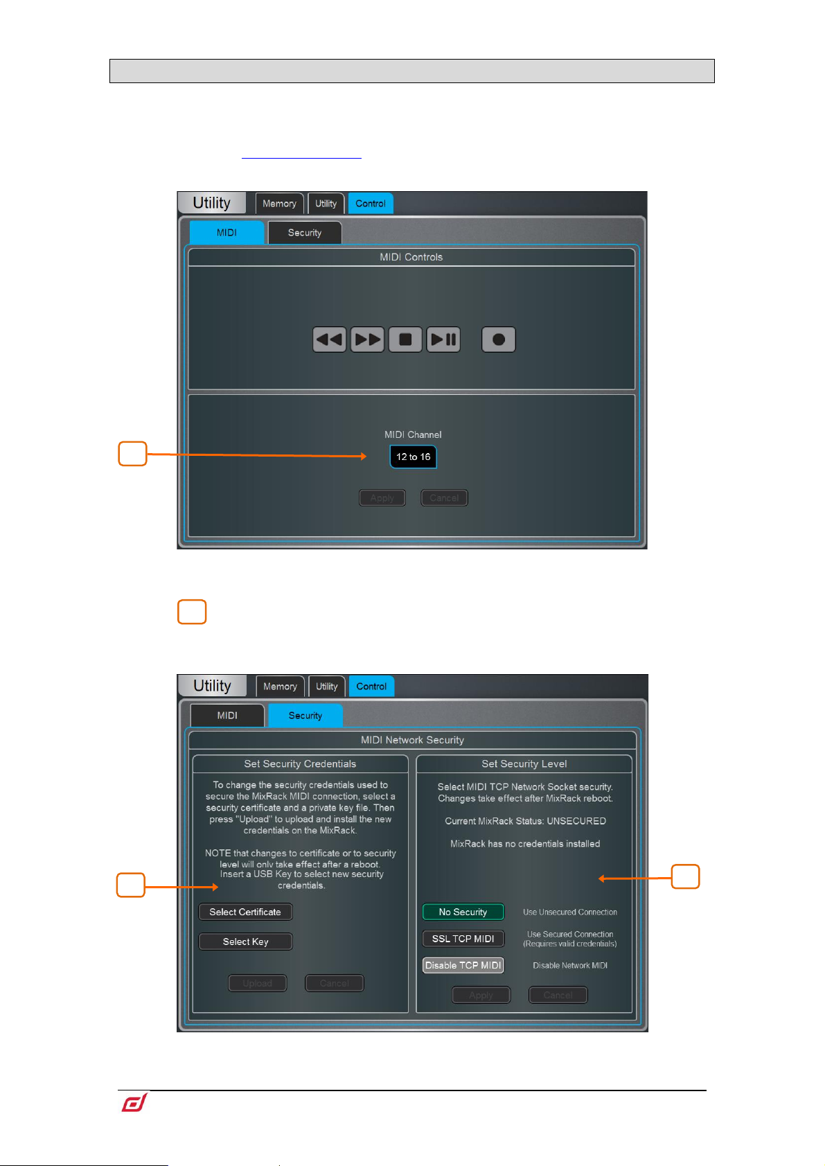
Firmware Reference Guide
96
V1.9
11.8 Control / MIDI
1
1
2
1
MIDI messages are sent/received over TCP and are available via any Network port on the dLive Surface or
MixRack.
For further information please refer to the dLive MIDI Over TCP/IP Protocol
document at www.allen-heath.com.
MIDI – Use this page to assign the MIDI channels and operate MIDI Transport
Controls (MTC).
Select the range of MIDI Channels dLive messages will use and respond to.
Multiple channels are used to address all Input and Mix channels.
Security – Use this page to configure Security options for MIDI Control. Clients can
be configured to use an SSL connection.
Page 97

Firmware Reference Guide
97
V1.9
Select a Certificate and private Key file from a USB storage device and press
1
2
Upload to install the new credentials.
Select the Security Level. Choose No Security for an unsecured connection,
SSL TCP MIDI for a secure SSL connection, or Disable TCP MIDI to disable all MIDI
control to/from the dLive.
Changes to Security settings will only take effect after a MixRack reboot.
Page 98
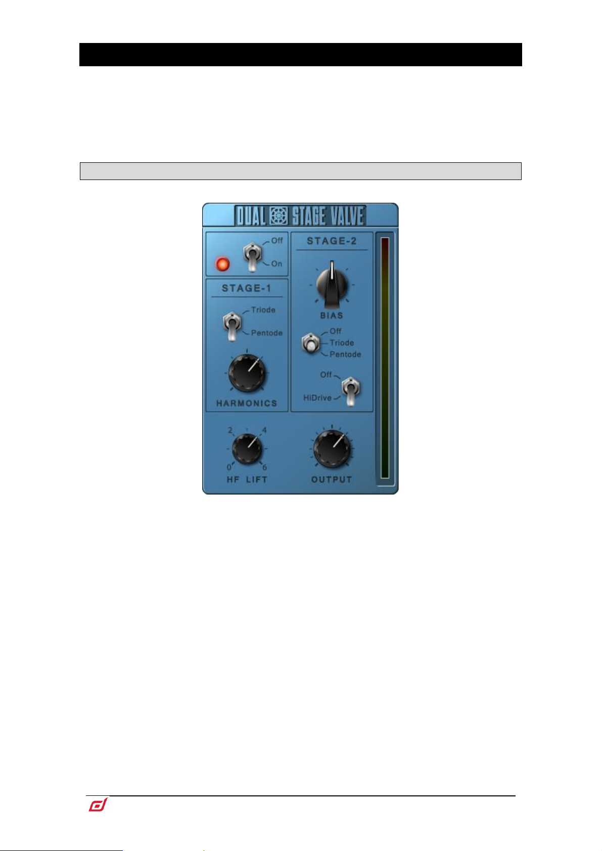
Firmware Reference Guide
98
V1.9
12. Appendix A – DEEP Processing and RackExtra FX
DEEP processing embeds class-leading compressors and processing emulations directly within the Input
and Mix channels. An array of bespoke algorithms can be inserted on the fly without burning FX slots and
without the setup, latency and licence hassles associated with external plug-ins.
The RackExtra FX portfolio combines the pristine quality and wide choice offered by boutique plug-ins with
the convenience and low latency of onboard processing.
12.1 DEEP Processing Preamp models
Dual-Stage Valve – Inspired by a known studio preamplifier, this model recreates the
distortion characteristics of valve circuits, from very subtle coloration to full overdrive.
It can be fully bypassed with the On/Off switch.
Stage-1 adds subtle tonal harmonic distortion and offers two modes which mirror the
typical valve topologies of analogue preamplifiers: Triode is richer in even order
distortion resulting in a musical, warm response; Pentode is stronger in odd order
distortion (predominantly 3rd), resulting in crisper, sharper sound.
Stage-2 provides overdriven valve emulation. It can be switched off circuit or to either
Triode or Pentode mode. Bias controls the level of overdrive. With HiDrive Off, it
produces pronounced ‘break up’ distortion and compression at high levels. HiDrive
changes the gain structure to produce a continuous overdrive effect.
The HF control adjusts the HF content to compensate for mid-range tonal lift and high
frequency compression.
The Output level is effectively a make-up gain to compensate for the level loss.
Page 99
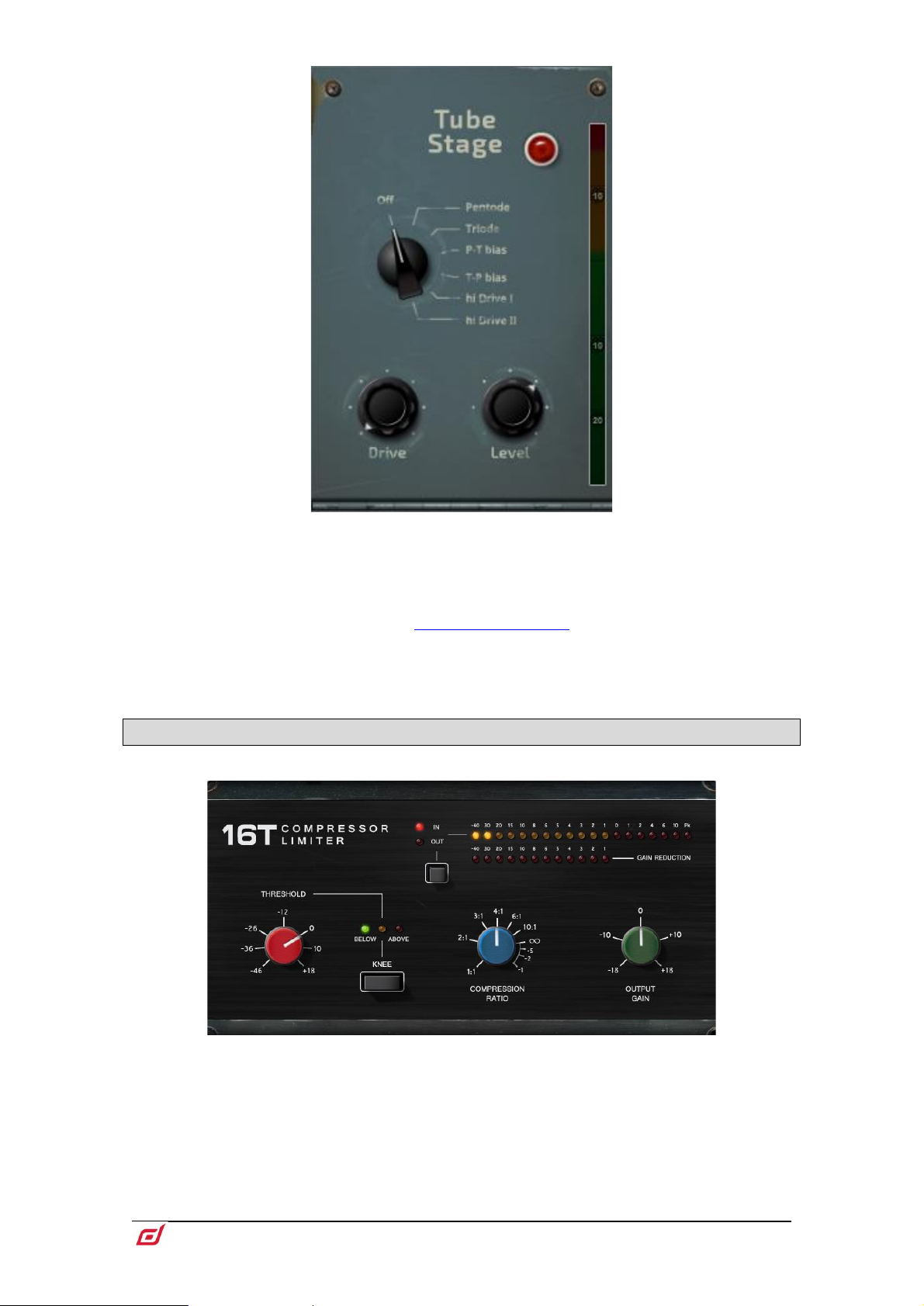
Firmware Reference Guide
99
V1.9
Tube Stage – Derived from our Dual-Stage Valve DEEP processor, this model
recreates the distortion characteristics of valve circuits, from very subtle coloration to
full overdrive, with a simplified control set. It can be fully bypassed with the On/Off
switch.
A number of modes are available via the rotary selector switch offering different
distortion characteristics – see the
The Drive control adjusts the amount of distortion applied to the signal.
The Level control is effectively a make-up gain to compensate for the level loss.
Dual-Stage Valve section for more information.
12.2 DEEP Processing Compressor models
16T - Inspired by an industry classic VCA based RMS compressor this model
produces a tight, punchy compression particularly useful with live bass and
percussion and also vocals, and with a very easy to use three rotary control interface.
Page 100
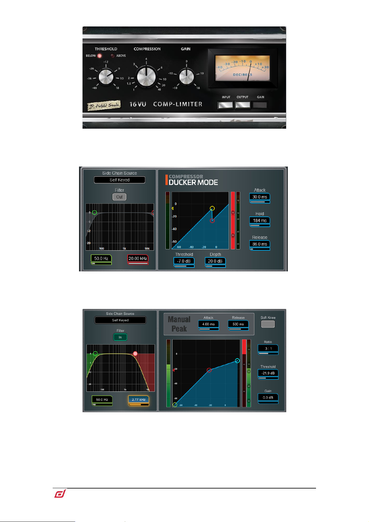
Firmware Reference Guide
100
V1.9
16VU - Based on an original vintage VCA based RMS compressor with VU needle
meter, with pleasant characteristic sound due to its non-linearity and distortion
artefacts, and also with a simple three rotary control interface.
Ducker - The Library for the Gate and Compressor processing blocks includes a
channel Ducker with key source selection and LPF/HPF filters, plus controls of
Threshold, Depth, Attack, Hold and Release.
Manual Peak - Offers the response of a peak based threshold detector with various
smoothing, auto hold/recovery schemes to minimise distortion. The algorithm is
capable of ultra fast attack time with minimal lag before onset.
 Loading...